

Page 1
Installation
Instructions
KD Halterung TIGi
Cold wire holder KD TIGi
DE
EN-US
Installationsanleitung
Installation instructions
42,0410,2684 002-10082022
Page 2

Page 3

Allgemeines
DE
Sicherheit
WARNUNG!
Gefahr durch Fehlbedienung und fehlerhaft durchgeführte Arbeiten.
Schwere Personen- und Sachschäden können die Folge sein.
Alle in diesem Dokument beschriebenen Arbeiten und Funktionen dürfen
▶
nur von technisch geschultem Fachpersonal ausgeführt werden.
Dieses Dokument vollständig lesen und verstehen.
▶
Sämtliche Sicherheitsvorschriften und Benutzerdokumentationen dieses
▶
Gerätes und aller Systemkomponenten lesen und verstehen.
WARNUNG!
Gefahr durch elektrischen Strom.
Schwere Personen- und Sachschäden können die Folge sein.
Vor Beginn der Arbeiten alle beteiligten Geräte und Komponenten ausschal-
▶
ten und von Stromnetz trennen.
Alle beteiligten Geräte und Komponenten gegen Wiedereinschalten sichern.
▶
Nach dem Öffnen des Gerätes mit Hilfe eines geeigneten Messgerätes si-
▶
cherstellen, dass elektrisch geladene Bauteile (beispielsweise Kondensatoren) entladen sind.
Allgemeines Die KD Halterung TIGi kann auf die TTB P/TFC Brennerkörper aufgebaut werden.
KD = Kaltdraht
3
Page 4

Lieferumfang
(1)
(2)
(3)
(4)
(5)
(6)
(1) TX8 Torx-Schlüssel
(2) Hand-Schlüssel
(3) FSC Zentralanschluss kom-
plett inkl. 5 m Teflonseele 1,2
(4) KD Halterung TIGi
(5) 5 x Kabelbinder lösbar
(6) 3 x Klettband
Ohne Abbildung:
diese Installationsanleitung
4
Page 5

KD Halterung TIGi montieren
DE
KD-Halterung
montieren
1
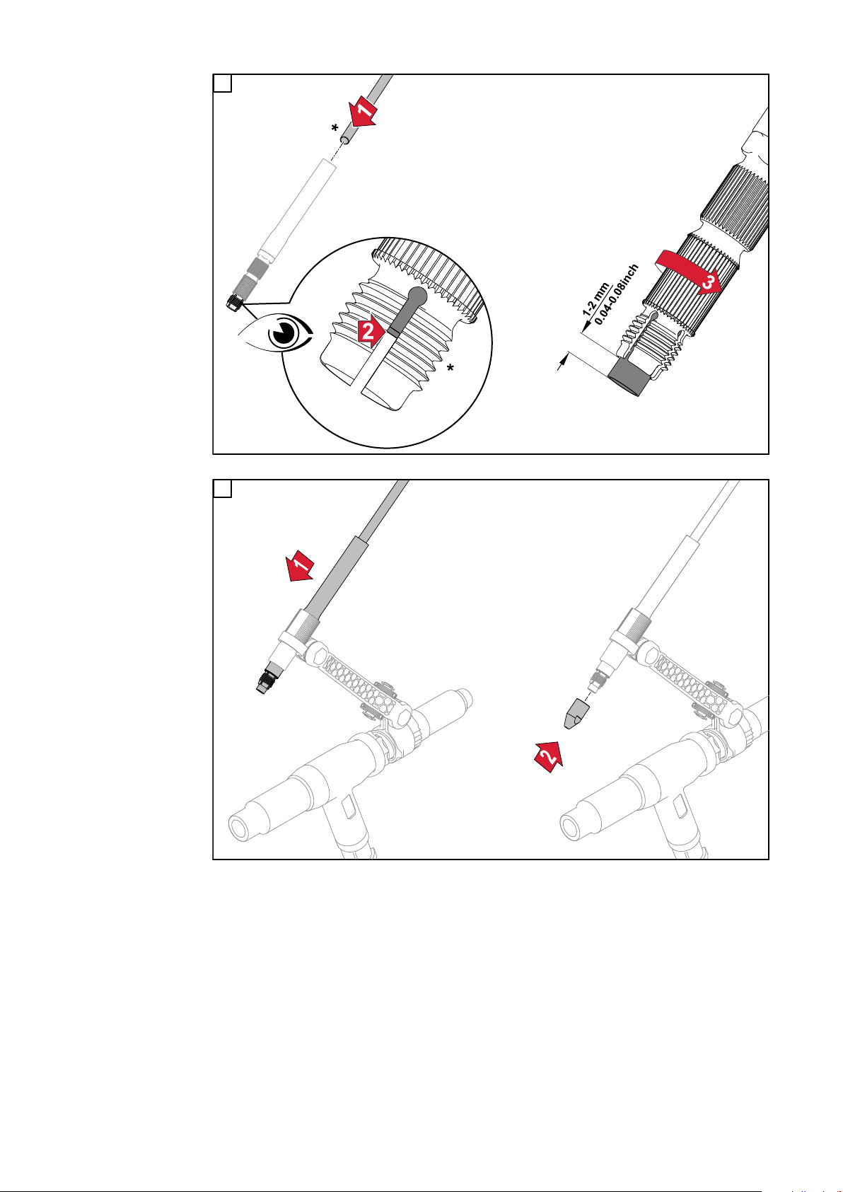
Draht-Führungsseele montieren
Die KD Halterung TIGi wird mit montierter Draht-Führungsseele ausgeliefert.
Die folgenden Arbeitsschritte zeigen die Montage der Draht-Führungsseele, die
Demontage erfolgt in umgekehrter Reihenfolge.
1
5
Page 6
2
* Seele bis auf Anschlag einschieben - die Seele muss bei der Spannzange sichtbar sein
3
6
Page 7

KD Halterung TIGi einrichten
max.
2
3
4
*
*
DE
KD-Halterung
einrichten
1
2
* Rändelmuttern bis auf Anschlag aufschrauben
7
Page 8
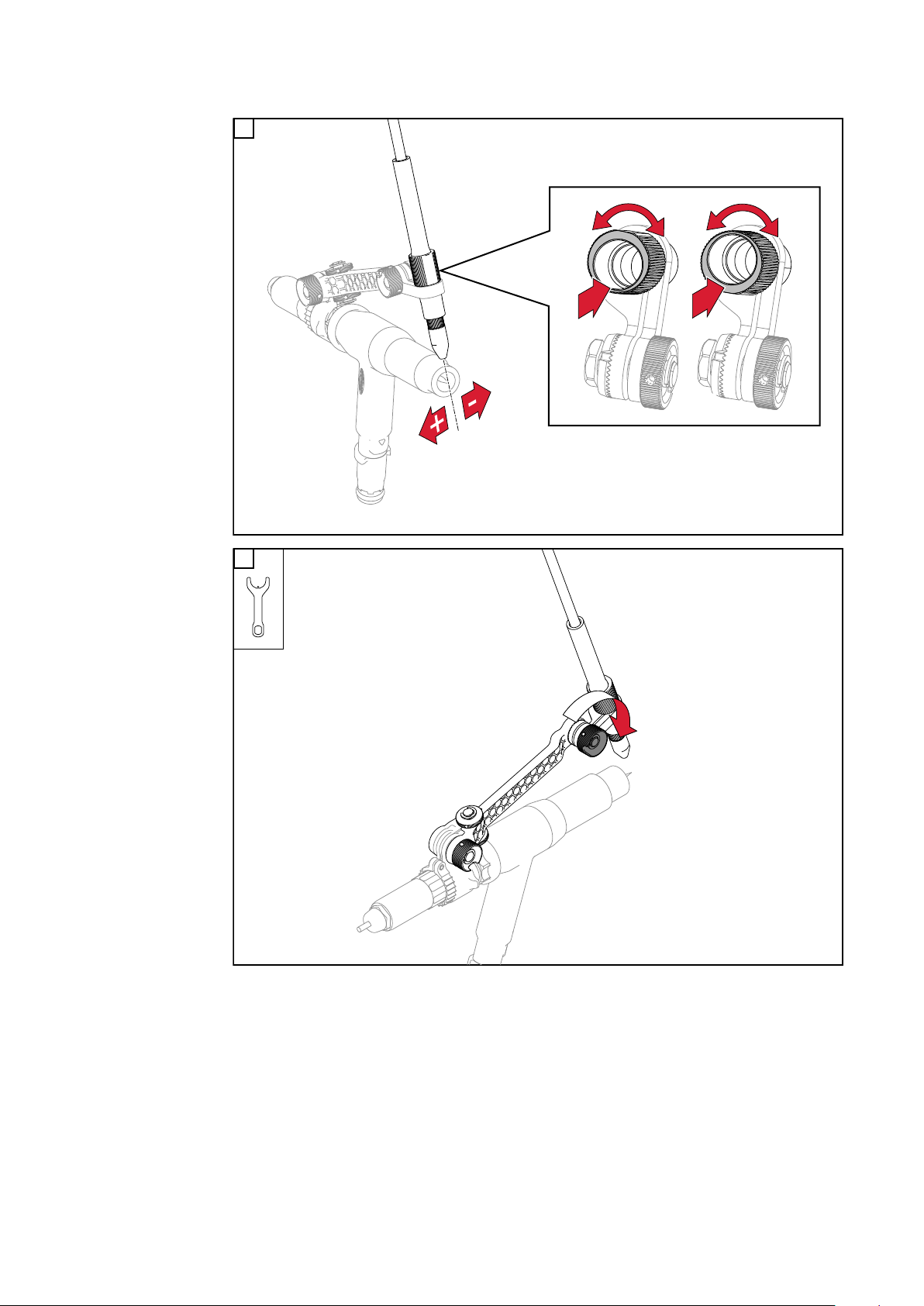
Feineinstellung mittels Exzenter:
3
4
8
Page 9

Schwenkarm-Anschlag einstellen:
Mit Hilfe der beiden Rändelmuttern und des darunter befindlichen Anschlages
kann die Position der Kaltdraht-Halterung exakt eingestellt und jederzeit wieder
hergestellt werden.
DE
Beide Rändelmuttern lösen
1
Leichten Druck auf den Schwenkarm (*) ausüben
2
Durch Drehen der unteren Rändelmutter die gewünschte Position des
3
Schwenkarms fein einstellen
Obere Rändelmutter festziehen
4
Hintere Rändelmutter des Schwenkarms festziehen
5
9
Page 10

KD Halterung TIGi um die Schweißbrenner-Längsachse verdrehen:
1
10
Page 11

Draht-Führungsseele am Schweißbrenner-
2
4
5
3
Schlauchpaket fixieren
Draht-Führungsseele am
Schweißbrenner-Schlauchpaket fixieren
Die Draht-Führungsseele wird mit den mitgelieferten lösbaren Kabelbindern und
den Klettbändern am Schweißbrenner-Schlauchpaket fixiert.
1
DE
11
Page 12

Schweißbrenner-Verschleißteile wechseln
3
3
4
5
Schweißbrenner-Verschleißteile
wechseln
Hintere Rändelmutter des Schwenkarms lösen
1
Schwenkarm nach hinten schwenken
2
Schweißbrenner-Verschleißteile gemäß Bedienungsanleitung des
3
Schweißbrenners wechseln
Schwenkarm bis auf Anschlag nach vor schwenken
4
Hintere Rändelmutter des Schwenkarms festziehen
5
Durch den voreingestellten Anschlag wird der Schwenkarm exakt gleich wie vor
dem Verschleißteil-Wechsel positioniert.
Details zum Einstellen des Anschlags siehe unter „Schwenkarm-Anschlag einstellen“ auf Seite 9.
12
Page 13

General
Safety
WARNING!
Danger from incorrect operation and work that is not carried out properly.
This can result in serious personal injury and damage to property.
All the work and functions described in this document must only be carried
▶
out by technically trained and qualified personnel.
Read and understand this document in full.
▶
Read and understand all safety rules and user documentation for this equip-
▶
ment and all system components.
WARNING!
Danger from electrical current.
This can result in serious personal injury and damage to property.
Before starting work, switch off all devices and components involved, and
▶
disconnect them from the grid.
Secure all devices and components involved so they cannot be switched back
▶
on.
After opening the device, use a suitable measuring instrument to check that
▶
electrically charged components (such as capacitors) have been discharged.
EN-US
General The TIGi KD holder can be mounted on the TTB P/TFC torch bodies.
KD = cold wire
13
Page 14

Scope of supply
(1)
(2)
(3)
(4)
(5)
(6)
(1) TX8 Torx wrench
(2) Hand wrench
(3) FSC central connector com-
plete incl. 5 m Teflon liner 1.2
(4) TIGi KD holder
(5) 5 x cable tie detachable
(6) 3 x Velcro strap
Not shown:
these Installation Instructions
14
Page 15

Fitting the TIGi KD holder
Fitting the KD
holder
1
EN-US
Fitting the inner
liner
The TIGi KD holder is delivered with the inner liner mounted.
The following steps show the installation of the inner liner; it is removed in reverse order.
1
15
Page 16

2
* Push the inner liner in as far as it will go - the inner liner must be visible at the collet
3
16
Page 17

Adjusting the TIGi KD holder
max.
2
3
4
*
*
Setting up the
KD holder
1
EN-US
2
* Screw on knurled nuts as far as they will go
17
Page 18

Fine adjustment by means of crank:
3
4
18
Page 19

Adjusting the swivel arm stop:
With the aid of the two knurled nuts and the stop underneath, the position of the
cold wire holder can be adjusted precisely and restored at any time.
EN-US
Loosen both knurled nuts
1
Apply slight pressure to the swivel arm (*)
2
Fine-tune the desired position of the swivel arm by turning the lower knurled
3
nut
Tighten upper knurled nut
4
Tighten the rear knurled nut of the swivel arm
5
19
Page 20

Rotating the TIGi KD holder around the longitudinal axis of the welding torch:
1
20
Page 21

Attaching the inner liner to the torch hosepack
2
4
5
3
Attaching the inner liner to the
torch hosepack
The inner liner is attached to the torch hosepack with the supplied detachable
cable ties and the Velcro straps.
1
EN-US
21
Page 22

Changing welding torch wear parts
3
3
4
5
Changing welding torch wear
parts
Loosen the rear knurled nut of the swivel arm
1
Swivel the swivel arm to the rear
2
Change the welding torch wear parts according to the Operating Instructions
3
for the welding torch
Swivel the swivel arm to the front as far as it will go
4
Tighten the rear knurled nut of the swivel arm
5
The preset stop positions the swivel arm exactly as it was before the wear part
was replaced.
For details on adjusting the stop, see "Adjusting the swivel arm stop" on page 19.
22
Page 23

EN-US
23
Page 24

Fronius International GmbH
Froniusstraße 1
4643 Pettenbach
Austria
contact@fronius.com
www.fronius.com
Under www.fronius.com/contact you will find the adresses
of all Fronius Sales & Service Partners and locations.
spareparts.fronius.com
SPAREPARTS
ONLINE
 Loading...