

Page 1

Testbox Motorwicklung CMT
CMT motor winding test box
Bedienungsanleitung
D
MIG/MAG-Systemerweiterung
Operating Instructions
GB
MIG/MAG system add-on
42,0410,1546 012012
Page 2

Page 3

Testbox Motorwicklung CMT
Sicherheit
Allgemeines Die Testbox Motorwicklung dient zur Überprüfung der Antriebseinheit eines Robacta
Bedienelemente
und Anschlüsse
Die nachfolgend angeführten Sicherheitshinweise gelten für alle in dieser Bedienungsanleitung beschriebenen Tätigkeiten:
WARNUNG! Fehlerhaft durchgeführte Arbeiten können schwerwiegende
Personen- und Sachschäden verursachen. Alle in der Bedienungsanleitung
beschriebenen Tätigkeiten dürfen nur von geschultem Fachpersonal durchgeführt werden. Das Fachpersonal muss von der Fa. Fronius eine Schulung
zur ordnungsgemäßen Bedienung des Gerätes erhalten haben.Die beschriebenen Tätigkeiten erst durchdurchführen, wenn folgende Dokumente vollständig gelesen und verstanden wurden:
- diese Bedienungsanleitung
- sämtliche Bedienungsanleitungen der Systemkomponenten,
insbesondere Sicherheitsvorschriften
Drive CMT oder PullMig CMT - Schweißbrenners.
Nr. Funktion
(1) Wahlschalter Motorwicklung
(4)
(1)
(2)
(3)
zur Auswahl der Motorwicklungen
(2) Anschluss Multimeter, Negativ
zum Anschluss eines
Digital-Multimeters
(3) Anschluss Multimeter, Positiv
zum Anschluss eines
Digital-Multimeters
(4) Anschluss Motorsteuerung
zum Anschluss eines
Schweißbrenners
1
Page 4

Motorwicklungen prüfen
Vorbereitung 1. Netzschalter der Stromquelle in Stellung - O - schalten
2. Stromquelle vom Netz trennen
3. Drahtelektrode aus dem Schlauchpaket entfernen
4. Schweißbrenner von allen anderen Systemkomponenten trennen
Motorwicklungen
prüfen
1. Schweißbrenner (1) anschließen
(1)
2. Digital-Multimeter für Widerstandsmessung vorbereiten
3. Digital-Multimeter anschließen
4. Mittels Wahlschalter Motorwicklung
die Motorwicklungen nacheinander
auswählen
5. Angezeigten Wert mit den Schwellenwerten vergleichen
6. Originalzustand des Schweißbrenner
wiederherstellen
Schwellenwerte: 3,9 - 6 Ohm
Wichtig! Übergangswiderstände, Widerstände der Motor- und Messleitungen
handelsüblicher Digital-Multimeter wurden
bei den angeführten Schwellenwerten
bereits berücksichtigt.
2
Page 5
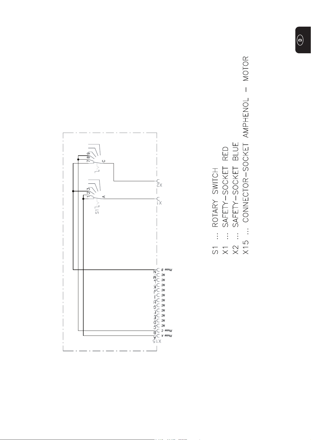
Schaltplan
3
Page 6

4
Page 7

CMT motor winding test box
Safety
General remarks The motor winding test box is used to test the drive unit of a Robacta Drive CMT or a
Controls and
connections
The following safety instructions apply to all activities described in these operating
instructions:
WARNING! Operating the equipment incorrectly can cause serious injury and
damage. All activities described in the operating instructions must only be
carried out by trained personnel. Only qualified technicians, who have attended the appropriate Fronius training course, are permitted to commission and
operate the device. Do not carry out the activities described until you have
fully read and understood the following documents:
- these operating instructions
- all the operating instructions for the system components, especially the
safety rules
PullMig CMT welding torch.
No. Function
(1) Motor winding selector switch
(4)
(1)
(2)
(3)
for selecting motor windings
(2) Multimeter connection, negative
used to connect a digital multimeter
(3) Multimeter connection, positive
used to connect a digital multimeter
(4) Motor control connection
used to connect a welding torch
1
Page 8

Testing motor windings
Preparations Turn power source mains switch to the „O“ position
2. Disconnect the power source from the mains
3. Feed the wire electrode out of the hosepack
4. Disconnect the welding torch from all other system components
Testing motor
windings
1. Connect the welding torch (1)
(1)
2. Prepare digital multimeter for resistance measurement
3. Connect digital multimeter
4. Use the motor winding selector switch
to select the motor windings one at a
time in sequence
5. Compare the indicated value with the
thresholds
6. restore the welding torch to its original
state
Thresholds: 3.9 - 6 ohms
Important! Allowance has already been
made in the listed thresholds for contact
resistances and resistances in the motor
leads and measuring leads on standard
digital multimeters.
2
Page 9

Circuit diagram
Page 10

4
Page 11

FRONIUS INTERNATIONAL GMBH
Froniusplatz 1, A-4600 Wels, Austria
Tel: +43 (0)7242 241-0, Fax: +43 (0)7242 241-3940
E-Mail: sales@fronius.com
www.fronius.com
Under http://www.fronius.com/addresses you will find all addresses
www.fronius.com/addresses
of our Sales & service partners and Locations.
ud_fr_st_so_00082 012011
 Loading...