

Page 1

Field Adjustable Trip Points
Fronius IG Plus USA
Fronius IG Plus V USA
Fronius CL USA
USA
Operating Instructions
Grid connected inverters for
photovoltaic systems
42,0410,1517 012011
Page 2

Page 3

IMPORTANT SAFETY
INSTRUCTIONS
SAVE THESE INSTRUCTIONS
Safety
General
Safety Instructions
WARNING! Incorrect operation and work performed incorrectly
can cause serious injury & damage! Only qualified staff are
authorized to install your Fronius IG Plus and only within the
scope of the respective technical regulations. Do not start
operation or carry out maintenance work before you have read
the chapter ‘Safety Instuctions’!
The inverters Fronius IG Plus, Fronius IG Plus V and Fronius CL are
provided with field adjustable trip points. This manual contains important
instructions for setting the field adjustable trip points of the Fronius IG
Plus, the Fronius IG Plus V and the Fronius CL.
The following section ‘Safety Instructions’ contains different Warnings. A
Warning describes a hazard to equipment or personnel. It calls attention
to a procedure or practice, which, if not correctly performed or adhered to,
could result in damage to or destruction of part or all of the Fronius equipment and/or other equipment connected to the Fronius equipment or
personal injury.
Page 4

Page 5

Safety Instructions
DANGER!
WARNING!
CAUTION!
NOTE
Important
“DANGER!“ indicates an imminently hazardous situation which, if not
avoided, will result in death or serious injury.
“WARNING!“ indicates a potentially hazardous situation which, if not
avoided, will result in death or serious injury.
“CAUTION!“ indicates a potentially harmful situation which, if not avoided,
may result in minor and moderate injury or property damage.
“NOTE“ indicates a situation which could adversely affect work results and
may cause damage to equipment.
“Important“ indicates practical tips and other useful information. It is not a
signal word for a harmful or dangerous situation.
General
Please pay special attention when one of the above symbols appears in the
manual.
This equipment has been manufactured using state-of-the-art technology
and in accordance with general safety regulations. However, incorrect
operation or misuse may endanger:
- the life and well-being of the operator or third parties
- the equipment and other property of the owner/operator
- the efficient operation of the equipment.
All persons involved with equipment startup, service and maintenance must:
- be suitably qualified
- be familiar with electrical installations
- have completely read and followed these operating instructions
The operating instructions must be available at the equipment location at all
times. In addition to the operating instructions, all applicable local rules and
regulations regarding accident prevention and environmental protection must
also be followed.
All safety instructions and warning signs on the equipment itself:
- must be maintained in legible condition
- must not be damaged
- must not be removed
- must not be covered or painted over
I
ud_fr_se_sv_01381 022009
Page 6

General
(continued)
For information about where the safety instructions and warning signs are
located on the equipment, please refer to the “General“ section of your
equipment’s operating instructions.
Any equipment malfunctions which might impair safety must be remedied
immediately before the device is turned on.
Your safety is at stake.
Intended Use
Ambient Conditions
The equipment may only be operated in compliance with its intended use.
Any other purpose does not constitute intended use. The manufacturer is not
responsible for any damages resulting from unintended use.
Intended use also includes:
- reading and complying with all general information as well as safety
information and warnings from the operating instructions
- compliance with all inspection and maintenance requirements
- installation as per operating instructions
Where appropriate, the following guidelines should also be applied:
- Utility company regulations regarding grid feed-in
- Information from solar module manufacturer
Operation and/or storage of the device outside of the stipulated range does
not constitute intended use. The manufacturer is not responsible for any
damages resulting from unintended use.
Please refer to the technical data in your operating instructions for information about permitted ambient conditions.
Qualified Personnel
The service information in these operating instructions is only intended for
qualified personnel. An electrical shock can be fatal. Please do not carry out
any activities other than those referred to in the documentation even if you
are suitably qualified.
All cables and wires must be secured, undamaged, insulated and adequately
dimensioned. Loose connections, scorched, damaged or under-dimensioned
cables and wires must be repaired immediately by an authorized specialist.
Maintenance and repair may only be carried out by an authorized specialist.
The use of third-party parts does not guarantee that they were designed and
manufactured according to operational demands and safety requirements.
Use only original spare parts (also applies to standard parts).
Do not carry out any alterations, installations or modifications to the device
without first obtaining the manufacturer’s permission.
Immediately replace any components that are not in perfect condition.
ud_fr_se_sv_01381 022009
II
Page 7

Safety Precautions at Equipment
Location
When installing devices with air vents, make sure that cool air can flow freely through the
vents unobstructed. The device should only be operated in accordance with the protection class listed on the rating plate.
Information on
Noise Emission
Values
EMC Device
Classifications
The inverter generates a maximum sound power level of <80dB(A) (ref.
1pW) at full-load operation according to IEC 62109-1.
The cooling of the device takes place via an electronic temperature control
system at the lowest possible noise level and depends on the power used,
ambient temperature and the soiling level of the device, etc.
A workplace-related emissions value cannot be provided for this device
because the actual noise level that occurs depends strongly on the installation situation, the grid quality, the surrounding walls and the general properties
of the space.
Devices of emission class A:
- Are only for use in industrial areas.
- Can cause line-bound and radiated interference in other areas.
Devices of emission class B:
- Meet the emission requirements for residential and industrial areas. This
is also true for residential areas in which the energy is supplied from the
public low voltage grid.
EMC device classification as per rating plate or technical data
EMC Precautions In special cases, there may still be interference for the specified application
area despite maintaining standardized emission limit values (e.g. when
sensitive equipment is located at the setup location or when the setup
location is near radio or television receivers).
In this case, the operator is obliged to take proper action to rectify the
situation.
Grid connection
Devices with a high output (> 16 A) can influence the voltage quality of the
grid due to a high current input into the main supply.
This can affect several device types in the form of:
- Connection limitations
- Requirements regarding permitted mains impedance
- Requirements regarding minimum required short circuit power
*)
for each interface to the public grid
*)
*)
See technical data
In this case, the operator or the user of the device must make sure whether
or not the device may be connected, if necessary by contacting the power
supply company.
III
ud_fr_se_sv_01381 022009
Page 8

Electrical Installations
Electrical installations may only be carried out in accordance with relevant
national and local standards and regulations.
ESD Precautions
Safety Precautions in NormalOperation
Safety Markings
Danger of damage to electronic components due to electrostatic discharge.
Take appropriate ESD precautions when replacing and installing components.
The device should only be operated when all safety equipment is fully functional. If safety equipment is not fully functional, there is a danger to:
- the life and well-being of the operator or third parties
- the equipment and other property of the owner/operator
- the efficient operation of the equipment
Safety equipment that is not fully functional must be repaired by an authorized specialist before the device is turned on.
Never bypass or disable safety equipment.
Equipment with the CE marking fulfils the basic requirements of the Guideline Governing Low-Voltage and Electromagnetic Compatibility. (For more
information, please see the attachment and/or the “Technical Data“ section in
your documentation).
Disposal
Data Security
Copyright
This device should not be disposed of in residential waste.
To comply with European Directive 2002/96/EC on Waste Electrical and
Electronic Equipment and its implementation as national law, electrical
equipment that has reached the end of its life must be collected separately
and returned to an approved recycling facility. Any device that you no longer
require must be returned to your dealer or you must find an approved collection and recycling facility in your area.
Ignoring this EU Directive may have adverse affects on the environment and
your health.
The user is responsible for backing up data relating to changes made to
factory settings. The manufacturer will not accept liability if personal settings
are deleted.
The manufacturer maintains the copyright to these operating instructions.
Text and illustrations are technically correct at the time of going to print. The
right to make modifications is reserved. The contents of the operating instructions shall not provide the basis for any claims whatsoever on the part
of the purchaser. We would be grateful for any comments or suggestions
regarding improvements and/or error corrections for the operating instructions.
ud_fr_se_sv_01381 022009
IV
Page 9

Table of Contents
Keys and Symbols on the Inverter ..................................................................................... 2
Keys and Symbols ......................................................................................................... 2
Display ........................................................................................................................... 3
Parameters in the Setup Menu for Field Adjustable Trip Points ......................................... 5
Voltage Limit Values ...................................................................................................... 5
Frequency Limit Values.................................................................................................. 6
Start Time....................................................................................................................... 7
Voltage Limit Values for Neutral Conductor Monitoring ................................................. 7
Fronius IG Plus - Field Adjustable Trip Points in the public grid......................................... 8
General .......................................................................................................................... 8
208 V Delta .................................................................................................................... 8
208 V Delta: 120 V WYE ............................................................................................... 8
240 V Delta .................................................................................................................... 8
240 V: 120 V Stinger ...................................................................................................... 9
240 V: 120 V Split Phase ............................................................................................... 9
480 V Delta: 277 V WYE ............................................................................................... 9
Fronius CL - Field Adjustable Trip Points in the public grid .............................................. 10
General ........................................................................................................................ 10
208 V Delta .................................................................................................................. 10
208 V Delta: 120 V WYE ............................................................................................. 10
240 V Delta ................................................................................................................... 11
480 V Delta: 277 V WYE .............................................................................................. 11
Enter the Setup Menu for Field Adjustable Trip Points..................................................... 12
Requirements .............................................................................................................. 12
Enter the Setup Menu for Field Adjustable Trip Points ................................................ 12
Enter the access code ................................................................................................. 13
Setting and Displaying Field Adjustable Trip Points ......................................................... 15
Setting and Displaying Field Adjustable Trip Points - General ..................................... 15
Setting Example........................................................................................................... 15
Technical Data ................................................................................................................. 18
Field adjustable trip points ........................................................................................... 18
1
Page 10

Keys and Symbols on the Inverter
Keys and
Symbols
(1)
(3)(4)(5)(6)
Keys and Symbols on the inverters Fronius IG Plus and Fronius CL
Item Function
(1) Display
for displaying values, settings and menus
(2) Operating Status LED
for displaying the operating status
(3) ‘Enter’ key
for confirming a choice
(4) ‘Menu / Esc’ key
switching to the menu level (‘Menu’) or exit from the setup menu
(‘Esc’)
(2)
(5) ‘Down/Right’ key
depending on the selection:
for navigating down
for navigating right
(6) ‘Left/Up’ key
depending on the selection:
for navigating left
for navigating up
2
Page 11

Display
(1) (2) (3) (4) (5)
(13)
(12)
Display
Item Function
(1) Icons for the ‘Now’ display mode
(2) Icons for the ‘Day’ display mode
(3) Icons for the ‘Year’ display mode
(4) Icons for the ‘Total’ display mode
(5) Icons for the ‘Setup’ display mode
(6) Icons for operating conditions
... indicates the maximum value within the period of observation (depending on the display mode chosen)
(6)
(7)
(8)(9)(10)(11)
... indicates the minimum value within the period of observation (depending on the mode of display chosen)
Important The Min. and Max. values may not correspond to the absolute extreme values, as the measured
data are recorded at two second intervals.
... appears with data readings that are directly related to
the solar modules
... appears with AC data readings that are directly related
to the grid
... appears with data readings that are related directly to
the inverter
(7) area for unit display
for displaying the applicable measuring unit
(8) Icon for the ‘Enter’ key
(9) Icons for the ‘Menu/Esc’ key
(10) Icons for the ‘Down/Right’ key
(11) Icons for the ‘Left/Up’ key
3
Page 12

Display
(continued)
Item Function
(12) Area for data
for displaying the data value measured
(13) output bar (not active during setup adjustments)
indicates the power output fed into the grid at a given moment independent from the display mode chosen. The screen displays
% of the maximum possible output power of your solar inverter
4
Page 13

Parameters in the Setup Menu for Field Adjustable Trip Points
Voltage Limit
Values
Maximum inner limit voltage
Upper limit voltage between the AC terminals
of the inverter
Unit V
Setting range 106 - 248 at 208 V grid voltage
122 - 287 at 240 V grid voltage
141 - 324 at 277 V grid voltage
Factory setting 229 at 208 V grid voltage
264 at 240 V grid voltage
305 at 277 V grid voltage
Maximum inner limit voltage trip time
Time duration in which exceeding the upper
limit voltage is allowed. When the upper limit
voltage is exceeded longer than the set time,
the inverter stops supplying energy to the
grid.
The display switches between ‘UIL
‘UTRIP
Max
’.
Max
’ and
Unit P (grid cycles)
Setting range 1 - 255 at 208 V / 240 V / 277 V grid voltage
Factory setting 58 at 208 V / 240 V / 277 V grid voltage
Minimum inner limit voltage
Lower limit voltage between the AC terminals
of the inverter
Unit V
Setting range 105 - 247 at 208 V grid voltage
121 - 286 at 240 V grid voltage
140 - 323 at 277 V grid voltage
Factory setting 183 at 208 V grid voltage
211 at 240 V grid voltage
244 at 277 V grid voltage
Minimum inner limit voltage trip time
Time duration in which going below the lower
limit voltage is allowed. When the system
goes below the lower limit voltage longer than
the set time, the inverter stops supplying
energy to the grid.
The display switches between ‘UIL
‘UTRIP
Min
’.
Min
’ and
5
Page 14

Voltage Limit
Values
(continued)
Unit P (grid cycles)
Setting range 1 - 255 at 208 V / 240 V / 277 V grid voltage
Factory setting 118 at 208 V / 240 V / 277 V grid voltage
Frequency
Limit Values
Maximum inner limit frequency
Upper limit frequency
Unit Hz
Setting range Factory setting 60.49
Important The parameter ‘FREQIL
purposes only.
Maximum inner limit frequency trip time
Time duration in which exceeding the upper
limit frequency is allowed. When the upper
limit frequency is exceeded longer than the
set time, the inverter stops supplying energy
to the grid.
The display switches between ‘FREQIL
and ‘FREQTRIP
Max
’ cannot be set. It is for display
Max
’.
Max
’
Unit P (grid cycles)
Setting range Factory setting 9 at 208 V / 240 V / 277 V grid voltage
Important The parameter ‘FREQTRIP
Max
’ cannot be set. It is for display
purposes only.
Minimum inner limit frequency
Lower limit frequency
Unit Hz
Setting range 57.00 - 60.48
Factory setting 59.31
Minimum inner limit frequency trip time
Time duration in which going below the lower
limit frequency is allowed. When the system
goes below the lower limit frequency longer
than the set time, the inverter stops supplying
energy to the grid.
The display switches between ‘FREQIL
and ‘FREQTRIP
Min
’.
Min
’
6
Page 15

Frequency
Limit Values
(continued)
Unit P (grid cycles)
Setting range 1 - 17998 at 208 V / 240 V / 277 V grid voltage
Factory setting 9 at 208 V / 240 V / 277 V grid voltage
Start Time
Voltage Limit
Values for
Neutral Conductor Monitoring
Start initiation time
Grid monitoring time during the startup phase
During this time, the inverter checks the
power grid to determine whether or not all
values are within tolerances during the startup phase. If any values deviate from the
tolerance range, the inverter disconnects
from the power grid.
Unit s
Setting range 5 - 900
Factory setting 300
The voltage limit values for neutral conductor monitoring are only shown
at the following grids:
- 208 V with neutral conductor (Setup: 208VN)
- 240 V with neutral conductor (Setup: 240VN)
Maximum neutral conductor monitoring
voltage
Upper limit voltage between phase and neutral conductor
Unit V
Setting range 62 - 143
Factory setting 132
Minimum neutral conductor monitoring
voltage
Lower limit voltage between phase and neutral conductor
Unit V
Setting range 61 - 142
Factory setting 106
Important The time in which the system can exceed or fall below the
limit voltage. This corresponds to the ‘inner limit voltage trip time' set for
the voltage limit values:
- for ‘UNMON
- for ‘UNMON
Max
’ ... ‘UTRIP
Min
’ ... ‘UTRIP
Max
Min
’
’
7
Page 16

Fronius Single Phase Inverters - Field Adjustable
Trip Points in the public grid
General Different parameters can be set for the following Fronius single phase
inverters depending on the available power grid:
- Fronius IG Plus 3.0-1 / 3.8-1 / 5.0-1 / 6.0-1 / 7.5-1 / 10.0-1 / 11.4-1
- Fronius IG Plus V 3.0-1 / 3.8-1 / 5.0-1 / 6.0-1 / 7.5-1 / 10.0-1 / 11.4-1
208 V Delta
208 V Delta:
120 V WYE
=
=
12 0 °
~
UIL
12 0 °
~
L3
UIL
UNMON
208 V
208 V
120 V
208 V
L1
20 8 V
12 0 °
=
L1
120 °
=
~
120 V
N
~
20 8 V
208 V
120 V
12 0 °
12 0 °
Adjustable parameters:
-UIL
~
-UIL
-UIL
=
-UIL
L2L3
- FREQIL
- FREQIL
Max
Max
/ UTRIP
Min
Min
/ UTRIP
Max
Min
Min
Min
/ FREQTRIP
Min
-STARTINIT / STARTTIME
Adjustable parameters:
-UIL
~
-UIL
-UIL
=
-UIL
L2
- FREQIL
- FREQIL
Max
Max
/ UTRIP
Min
Min
/ UTRIP
Max
Min
Min
Min
/ FREQTRIP
Min
-STARTINIT / STARTTIME
-UNMON
-UNMON
Max
min
240 V Delta
L1
12 0 °
24 0 V
12 0 °
=
24 0 V
~
=
L2L3
8
=
12 0 °
~
240 V
UIL
Adjustable parameters:
-UIL
-UIL
-UIL
~
-UIL
- FREQIL
- FREQIL
Max
Max
/ UTRIP
Min
Min
/ UTRIP
Min
Min
/ FREQTRIP
-STARTINIT / STARTTIME
Max
Min
Min
Page 17

240 V:
120 V Stinger
=
12 0 °
~
L2
UIL
UNMON
240 V
12 0 °
=
L3
12 0 °
24 0 V
N
12 0 V12 0 V
=
L1
Adjustable parameters:
-UIL
-UIL
-UIL
~
-UIL
- FREQIL
- FREQIL
Max
Max
/ UTRIP
Min
Min
/ UTRIP
Min
Min
Max
Min
/ FREQTRIP
Min
-STARTINIT / STARTTIME
-UNMON
-UNMON
~
Max
min
240 V:
120 V Split
Phase
480 V Delta:
277 V WYE
=
180 °
N
120 V 120 V
L1 L2
240 V
480 V
27 7 V
=
480 V
120 °
L1
277 V
~
480V
N
27 7 V
UIL
UNMON
12 0 °
~
L3
12 0 °
Adjustable parameters:
-UIL
-UIL
-UIL
-UIL
- FREQIL
- FREQIL
Max
Max
/ UTRIP
Min
Min
/ UTRIP
Max
Min
Min
Min
/ FREQTRIP
Min
-STARTINIT / STARTTIME
-UNMON
-UNMON
Max
min
Adjustable parameters:
-UIL
~
-UIL
-UIL
=
-UIL
L2
- FREQIL
- FREQIL
Max
Max
/ UTRIP
Min
Min
/ UTRIP
Max
Min
Min
Min
/ FREQTRIP
Min
-STARTINIT / STARTTIME
UIL
=
~
9
Page 18

Fronius 3-Phase Inverters - Field Adjustable Trip
Points in the public grid
General Different parameters can be set for the following Fronius 3-phase inver-
ters depending on the available power grid:
- Fronius IG Plus 11.4-3 / 12.0-3
- Fronius IG Plus V 10.0-3 / 11.4-3 / 12.0-3
- Fronius CL 33.3 DELTA / 44.4 DELTA / 55.5 DELTA
- Fronius CL 36.0 WYE 277 / 48.0 WYE 277 / 60.0 WYE 277
208 V Delta
208 V Delta:
120 V WYE
12 0 °
L3
12 0 °
208 V
UIL
208 V
120 V
L1
20 8 V
12 0 °
=
208 V
~
L1
120 V
N
20 8 V
208 V
120 V
12 0 °
L2L3
12 0 °
Fronius IG Plus 11.4-3
Fronius IG Plus V 10.0-3
Fronius IG Plus V 11.4-3
Fronius CL 33.3 DELTA
Fronius CL 44.4 DELTA
Fronius CL 55.5 DELTA
Adjustable parameters:
-UIL
-UIL
-UIL
-UIL
- FREQIL
- FREQIL
Max
Max
/ UTRIP
Min
Min
/ UTRIP
Max
Min
Min
Min
/ FREQTRIP
Min
-STARTINIT / STARTTIME
Fronius IG Plus 11.4-3
Fronius IG Plus V 10.0-3
Fronius IG Plus V 11.4-3
Fronius CL 33.3 DELTA
Fronius CL 44.4 DELTA
L2
Fronius CL 55.5 DELTA
=
UIL
UNMON
120 °
Adjustable parameters:
-UIL
-UIL
~
-UIL
-UIL
- FREQIL
- FREQIL
Max
Max
/ UTRIP
Min
Min
/ UTRIP
Max
Min
Min
Min
/ FREQTRIP
Min
-STARTINIT / STARTTIME
-UNMON
-UNMON
10
Max
min
Page 19

240 V Delta
12 0 °
240 V
L1
24 0 V
24 0 V
12 0 °
Fronius IG Plus 11.4-3
Fronius IG Plus V 10.0-3
Fronius IG Plus V 11.4-3
Fronius CL 33.3 DELTA
Fronius CL 44.4 DELTA
L2L3
Fronius CL 55.5 DELTA
480 V Delta:
277 V WYE
12 0 °
=
~
UIL
Adjustable parameters:
IL
Max
Max
Min
Min
/ UTRIP
/ UTRIP
Min
Min
/ FREQTRIP
Max
Min
-U
-UIL
-UIL
-UIL
- FREQIL
- FREQIL
Min
-STARTINIT / STARTTIME
L1
12 0 °
120 °
=
277 V
480V
N
27 7 V
L2
~
12 0 °
480 V
27 7 V
L3
480 V
UIL
Fronius IG Plus 12.0-3
Fronius IG Plus V 12.0-3
Fronius CL 36.0 WYE 277
Fronius CL 48.0 WYE 277
Fronius CL 60.0 WYE 277
Adjustable parameters:
-UIL
-UIL
-UIL
-UIL
- FREQIL
- FREQIL
Max
Max
/ UTRIP
Min
Min
/ UTRIP
Max
Min
Min
Min
/ FREQTRIP
Min
-STARTINIT / STARTTIME
11
Page 20

Enter the Setup Menu for Field Adjustable Trip
Points
Requirements A 5-character access code is required to access Field Adjustable Trip
Points in the Setup menu. This access code will be provided by Fronius
upon request.
Enter the
Setup Menu
for Field Adjustable Trip
Points
1. Press the ‘Menu’ key
‘MENU’ is displayed
2. Select the ‘Setup’ mode using
the ‘Left’ or ‘Right’ keys
3. Press the ‘Enter’ key
‘STANDBY’ is displayed.
4. Press the ‘Menu’ key 5 x
12
‘CODE’ is displayed, the first
digit flashes.
5. Enter the access code
Page 21

Enter the
access code
‘CODE’ is displayed, the first
digit flashes.
1. Use the ‘Up’ and ‘Down’ keys to
select a value for the first digit
of the access code
2. Press the ‘Enter’ key
The second digit flashes.
3. Use the ‘Up’ and ‘Down’ keys to
select a value for the second
digit of the access code
4. Press the ‘Enter’ key
The third digit flashes.
5. Use the ‘Up’ and ‘Down’ keys to
select a value for the third digit
of the access code
6. Press the ‘Enter’ key
The fourth digit flashes.
7. Use the ‘Up’ and ‘Down’ keys to
select a value for the fourth
digit of the access code
8. Press the ‘Enter’ key
The fifth digit flashes.
9. Use the ‘Up’ and ‘Down’ keys to
select a value for the fifth digit
of the access code
10. Press the ‘Enter’ key
The access code flashes.
11. Press the ‘Enter’ key
13
Page 22

Enter the
access code
(continued)
The first parameter ‘UIL
Max
’ in
the setup menu for field adjustable trip points is displayed.
The setup menu for field adjustable trip points is now activated
on the inverter.
14
Page 23

Setting and Displaying Field Adjustable Trip
Points
Setting and
Displaying
Field Adjustable Trip
Points - General
1. Enter the setup menu for field adjustable trip points
2. Enter the access code
3. Select the desired parameter using the ‘Up’ and ‘Down’ keys
4. Press the ‘Enter’ key
The value of the selected parameter is displayed, the first digit flashes.
5. Select a value for the first digit of the parameter using the ‘Up’ and
‘Down’ keys
6. Press the ‘Enter’ key
The second digit flashes.
7. Repeat steps 5. and 6. for each digit of the parameter value, untill the
whole parameter value flashes
8. Press the ‘Enter’ key
The new value of the parameter is accepted, the parameter is displayed.
Setting Example
9. Press the ‘Esc’ key to exit the setup menu for field adustable trip
points.
The inverter starts the startup phase with the grid synchronization.
1. Enter the setup menu for field adjustable trip points
2. Enter the access code
The first parameter ‘UIL
the setup menu for field adjustable trip points is displayed.
3. Select the desired parameter
using the ‘Up’ and ‘Down’ keys
Max
’ in
15
Page 24
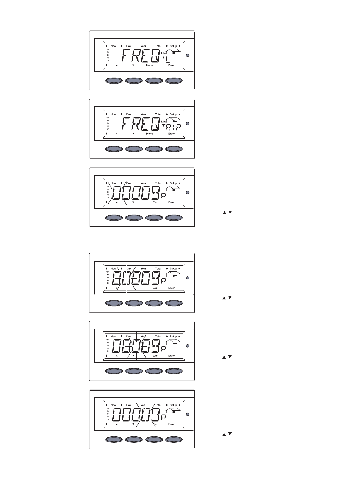
Setting Example
(continued)
e.g.: ‘FREQTRIP
Min
’
The display switches between
‘FREQIL
Min
’ and ...
... ‘FREQTRIP
Min
’.
4. Press the ‘Enter’ key
The value of ‘FREQTRIP
Min
’ is
displayed, the first digit flashes.
5. Use the ‘Up’ and ‘Down’ keys to
select a value for the first digit
6. Press the ‘Enter’ key
The second digit flashes
7. Use the ‘Up’ and ‘Down’ keys to
select a value for the second
digit
8. Press the ‘Enter’ key
The third digit flashes.
9. Use the ‘Up’ and ‘Down’ keys to
select a value for the third digit
10. Press the ‘Enter’ key
The fourth digit flashes.
11. Use the ‘Up’ and ‘Down’ keys to
select a value for the fourth
digit
12. Press the ‘Enter’ key
16
Page 25

Setting Example
(continued)
The fifth digit flashes.
13. Use the ‘Up’ and ‘Down’ keys to
select a value for the fifth digit
14. Press the ‘Enter’ key
The value of ‘FREQTRIP
Min
’
flashes.
15. Press the ‘Enter’ key
The new value of ‘FREQTRIP
is accepted, the display switches between ‘FREQIL
Min
’ and
...
... ‘FREQTRIP
Min
’.
16. Press the ‘Esc’ key to exit the
setup menu for field adustable
trip points.
Min
’
The inverter starts the startup
phase with the grid synchronization.
For more information about the startup phase, please see the operating
instructions for the inverter, chapter 'Operation', section 'Product Description' (Startup Phase, Test Procedure).
17
Page 26

Technical Data
Fronius IG
Plus
Field adjustable trip points 208 V 240 V 277 V
Nominal AC output voltage, 208 240 277
Line-to-Line, [V]
Operating AC voltage range 183-229 211-264 default, Line-to-Line, [V]
Adjustment range for 105-248 121-287 voltage, Line-to-Line, [V]
Voltage trip limit accuracy, 1.0 1.0 Line-to-Line [% of nominal value]
Operating AC voltage range, 106-132 106-132 244-305
Line-to-Neutral, [V]
Adjustment range for voltage, 61-143 61-143 138-324
Line-to-Neutral, [V]
Adjustment range for voltage 0.016-4.25 0.016-4.25 0.016-4.25
clearing time [s]
Voltage trip limit accuracy, 1.0 1.0 1.0
Line-to-Neutral [% of nom. value]
Nominal output frequency [Hz] 60 60 60
Operating frequency 59.3-60.5 59.3-60.5 59.3-60.5
range [Hz]
Adjustment range for 57.0-60.48 57.0-60.48 57.0-60.48
frequency [Hz]
Adjustment range for frequency 0.016-300 0.016-300 0.016-300
clearing time [s]
Frequency trip limit accuracy [ms] 16.66
Detection time [ms] 25
(2)
(1)
16.66
25
(2)
(1)
16.66
(2)
25
(1)
Reconnect time default [s] 300 300 300
Adjustment range for reconnect 5-900 5-900 5-900
time [s]
(1)
16.66 ms are equivalent to 1 cycle
(2)
25 ms are equivalent to 1.5 cycles
18
Page 27

Fronius IG
Plus V
Field adjustable trip points 208 V 240 V 277 V
Nominal AC output voltage, 208 240 277
Line-to-Line, [V]
Operating AC voltage range 183-229 211-264 default, Line-to-Line, [V]
Adjustment range for 105-248 121-287 voltage, Line-to-Line, [V]
Voltage trip limit accuracy, 1.0 1.0 Line-to-Line [% of nominal value]
Operating AC voltage range, 106-132 106-132 244-305
Line-to-Neutral, [V]
Adjustment range for voltage, 61-143 61-143 138-324
Line-to-Neutral, [V]
Adjustment range for voltage 0.016-4.25 0.016-4.25 0.016-4.25
clearing time [s]
Voltage trip limit accuracy, 1.0 1.0 1.0
Line-to-Neutral [% of nom. value]
Nominal output frequency [Hz] 60 60 60
Operating frequency 59.3-60.5 59.3-60.5 59.3-60.5
range [Hz]
Adjustment range for 57.0-60.48 57.0-60.48 57.0-60.48
frequency [Hz]
Adjustment range for frequency 0.016-300 0.016-300 0.016-300
clearing time [s]
Frequency trip limit accuracy [ms] 16.66
Detection time [ms] 25
(2)
(1)
16.66
25
(2)
(1)
16.66
(2)
25
(1)
Reconnect time default [s] 300 300 300
Adjustment range for reconnect 5-900 5-900 5-900
time [s]
(1)
16.66 ms are equivalent to 1 cycle
(2)
25 ms are equivalent to 1.5 cycles
19
Page 28

Fronius CL
Field adjustable trip points 208 V 240 V 277 V
Nominal AC output voltage, 208 240 277
Line-to-Line, [V]
Operating AC voltage range 183-229 211-264 default, Line-to-Line, [V]
Adjustment range for 105-248 121-287 voltage, Line-to-Line, [V]
Voltage trip limit accuracy, 1.5 1.5 Line-to-Line [% of nominal value] -
Operating AC voltage range, 106-132 106-132 244-305
Line-to-Neutral, [V]
Adjustment range for voltage, 61-143 61-143 138-324
Line-to-Neutral, [V]
Adjustment range for voltage 0.016-4.25 0.016-4.25 0.016-4.25
clearing time [s]
Voltage trip limit accuracy, 1.5 1.5 1.5
Line-to-Neutral [% of nom. value]
Nominal output frequency [Hz] 60 60 60
Operating frequency 59.3-60.5 59.3-60.5 59.3-60.5
range [Hz]
Adjustment range for 57.0-60.48 57.0-60.48 57.0-60.48
frequency [Hz]
Adjustment range for frequency 0.016-300 0.016-300 0.016-300
clearing time [s]
Frequency trip limit accuracy [ms] 16.66
Detection time [ms] 25
(2)
(1)
16.66
25
(2)
(1)
16.66
(2)
25
(1)
Reconnect time default [s] 300 300 300
Adjustment range for reconnect 5-900 5-900 5-900
time [s]
(1)
16.66 ms are equivalent to 1 cycle
(2)
25 ms are equivalent to 1.5 cycles
20
Page 29

Fronius Worldwide - www.fronius.com/addresses
Fronius International GmbH
4600 Wels, Froniusplatz 1, Austria
E-Mail: pv@fronius.com
http://www.fronius.com
Under http://www.fronius.com/addresses you will find all addresses of our sales branches and partner firms!
Fronius USA LLC Solar Electronics Division
USAA
10421 Citation Drive, Suite 1100, Brighton, MI 48116
E-Mail: pv-us@fronius.com
http://www.fronius-usa.com
ud_fr_se_so_00913 012011
 Loading...