

Page 1

Fronius prints on elemental chlorine free paper (ECF) sourced from certified sustainable forests (FSC).
/ Perfect Charging / Perfect Welding / Solar Energy
Spannsystem Reamer Twin
Reamer Twin Clamping System
Installationsanleitung
DEEN-US
Schweißbrenner-Reinigung
Installation Instructions
Welding torch cleaning
42,0410,2526 001-04092019
Page 2

2
Page 3

Inhaltsverzeichnis
Lieferumfang .............................................................................................................................................. 5
Lieferumfang......................................................................................................................................... 5
Sicherheit ................................................................................................................................................... 6
Sicherheit.............................................................................................................................................. 6
Sicherstellen, dass das Reinigungsgerät druckluftfrei ist......................................................................7
Spannsystem Reamer Twin einbauen ....................................................................................................... 8
Bestehende Spannvorrichtungs-Elemente demontieren ...................................................................... 8
Spannsystem Reamer Twin einbauen.................................................................................................. 9
DE
3
Page 4

4
Page 5
Lieferumfang
DE
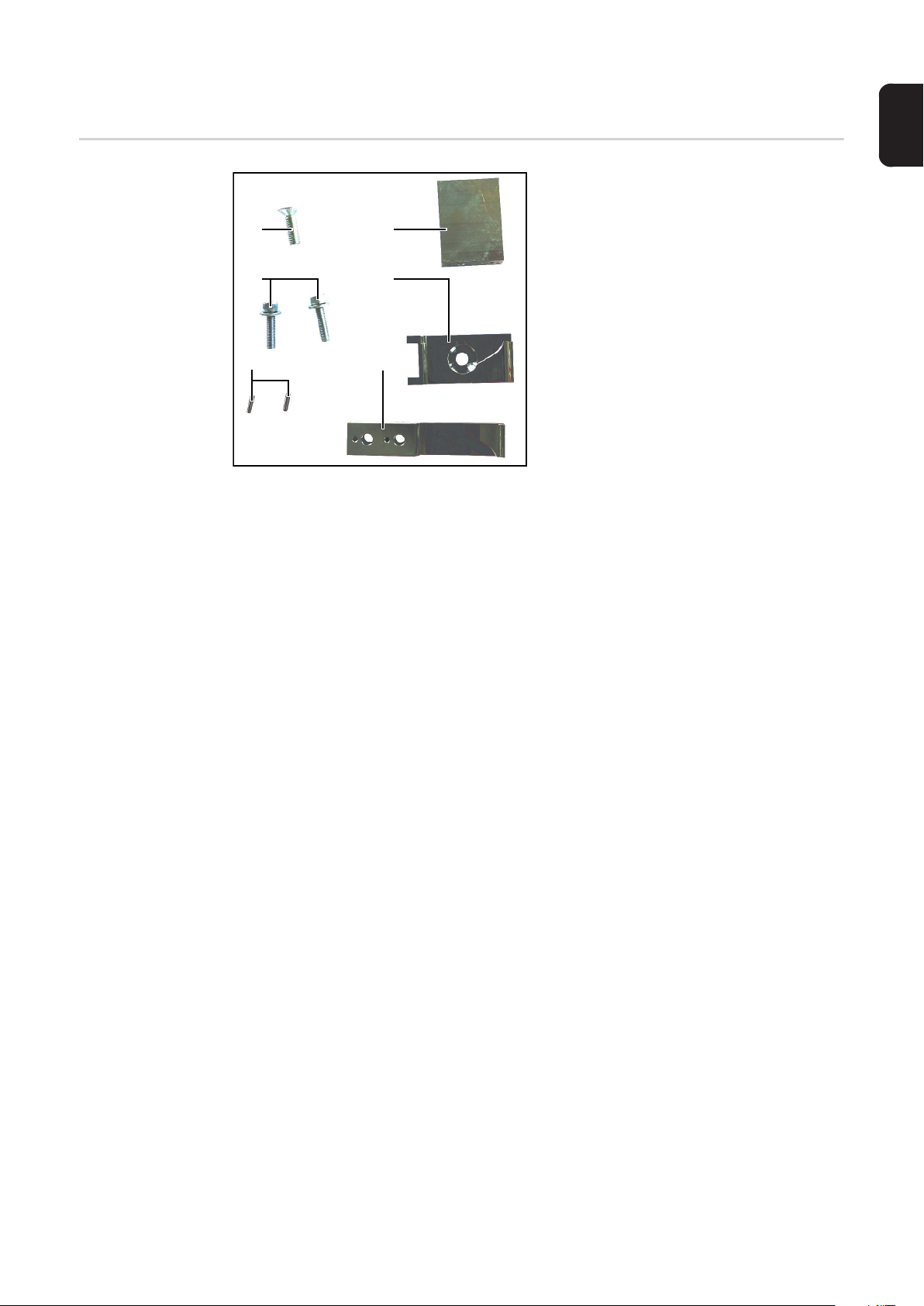
Lieferumfang
(1)
(2)
(3)
(4)
(5)
(6)
(1) Innensechskant-Senkkopfschrau-
be M8x25
(2) 2 Innensechskant-Schrauben
M6x25, jeweils mit Scheibe
(3) 2 Pass-Stifte 3x12
(4) Spannvorrichtungs-Element 1
(5) Spannvorrichtungs-Element 2
(6) Spannvorrichtungs-Element 3
5
Page 6

Sicherheit
Sicherheit Die nachfolgend angeführten Sicherheitsvorschriften bei allen im Kapitel „Spannsystem
Reamer Twin einbauen“ beschriebenen Arbeiten befolgen!
WARNUNG!
Gefahr durch Fehlbedienung und fehlerhaft durchgeführte Arbeiten.
Schwerwiegende Personen- und Sachschäden können die Folge sein.
► Alle in dieser Installationsanleitung angeführten Arbeiten dürfen nur von geschultem
Fachpersonal durchgeführt werden.
► Alle angeführten Arbeiten erst durchführen und alle beschriebenen Funktionen erst an-
wenden, wenn folgende Dokumente vollständig gelesen und verstanden wurden:
► Diese Bedienungsanleitung.
► Sämtliche Bedienungsanleitungen der Systemkomponenten, insbesondere Sicher-
heitsvorschriften.
WARNUNG!
Gefahr durch automatisch anlaufende Maschinen.
Schwerwiegende Personen- und Sachschäden können die Folge sein.
► Ergänzend zu dieser Bedienungsanleitung sind die Sicherheitsvorschriften des Robo-
ter- und Schweißsystem-Herstellers zu beachten.
► Überzeugen Sie sich zu Ihrer persönlichen Sicherheit, dass alle Schutzmaßnahmen im
Arbeitsbereich des Roboters getroffen sind und für die Dauer Ihres Aufenthaltes in die-
sem Bereich auch bestehen bleiben.
WARNUNG!
Gefahr durch mechanisch bewegte Bauteile, herumfliegende Teile (Späne, ...) und
aus den Trennmittel-Einsprühdüsen austretendes Druckluft/Trennmittel-Gemisch.
Schwere Verletzungen können die Folge sein.
► Vor Beginn von Arbeiten am Reinigungsgerät oder den damit verbunden Systemkom-
ponenten:
► Die kundenseitige Druckluft- und Spannungsversorgung vom Reinigungsgerät und
den damit verbundenen Systemkomponenten trennen und sicherstellen, dass die
Druckluft- und Spannungsversorgung bis zum Abschluss aller Arbeiten getrennt bleibt.
► Sicherstellen, dass das Reinigungsgerät druckluftfrei ist - die hierfür notwendigen Ar-
beitsschritte dem nachfolgenden Abschnitt „Sicherstellen, dass das Reinigungsgerät
druckluftfrei ist“ entnehmen.
6
Page 7
WARNUNG!
Sicherstellen,
dass das Reinigungsgerät
druckluftfrei ist
Gefahr, wenn das Reinigungsgerät und die damit verbundenen Systemkomponenten mit Spannung und/oder Druckluft versorgt werden.
Schwere Verletzungen können die Folge sein, durch:
Rotierenden Reinigungsfräser / rotierende Reinigungsbürste.
Auf/ab fahrende Hubvorrichtung.
Aus/ein fahrende Spannvorrichtung Gasdüse.
Aktivierten Drahtabschneider.
Herumfliegende Teile (Späne, ...).
Aus den Trennmittel-Einsprühdüsen austretendes Druckluft/Trennmittel-Gemisch.
► Wenn Arbeiten am Reinigungsgerät durchgeführt werden müssen, während das Rei-
nigungsgerät mit Spannung und/oder Druckluft versorgt ist:
► Von Reinigungsfräser / Reinigungsbürste, Hubvorrichtung, Spannvorrichtung Gasdü-
se, Drahtabschneider und Trennmittel-Einsprühdüsen mit dem Körper, insbesondere
mit den Händen, dem Gesicht und Haaren sowie Gegenständen und sämtlichen Klei-
dungsstücken fernbleiben.
► Gehörschutz tragen.
► Schutzbrille mit Seitenschutz tragen.
Um sicherzustellen, dass das Reinigungsgerät druckluftfrei ist, muss versucht werden, das
Reinigungsgerät kurzzeitig ohne vorhandene Druckluft-Versorgung zu aktivieren. Hierfür
wie folgt vorgehen:
Schutzmaßnahmen treffen:
1
- Reinigungsfräser / Reinigungsbürste, Hubvorrichtung, Spannvorrichtung Gasdüse, Drahtabschneider und Trennmittel-Einsprühdüsen könnten aktiviert werden.
Deshalb mit dem Körper, insbesondere mit den Händen, dem Gesicht und Haaren, sowie Gegenständen und sämtlichen Kleidungsstücken von den oben angeführten Bauteilen fernbleiben
- Gehörschutz tragen
- Schutzbrille mit Seitenschutz tragen
Sicherstellen, dass das Reinigungsgerät von der Druckluft-Versorgung getrennt ist
2
DE
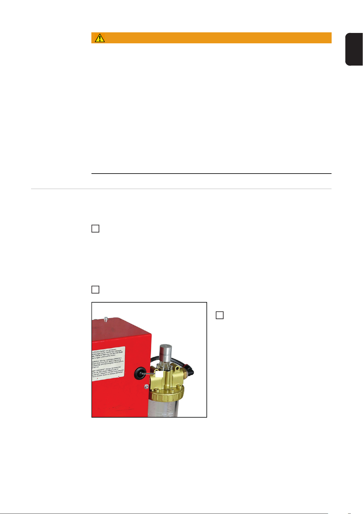
(1)
Falls ein Drahtabschneider vorhanden ist:
Taste für das Einsprühen (1) an der
3
Rückseite des Gerätes 2 s drücken
Erfolgt kein Einsprühvorgang, ist das Gerät
druckluftfrei.
7
Page 8

Spannsystem Reamer Twin einbauen
Bestehende
Spannvorrichtungs-Elemente
demontieren
(7)
(7)
(7)
(8)
(9) (9)
(7)
(10)
(7)
5 Innensechskant-Schrauben (7) lösen
1
- Schlüsselweite 3
Gehäusemantel (8) abnehmen
2
2 Innensechskant-Schrauben (9) lösen
3
- Schlüsselweite 5
Spannvorrichtungs-Element (10), be-
4
stehend aus 3 miteinander verschraubten Teilen, abnehmen
(12)
(11)
Innensechskant-Senkkopfschraube
5
(11) lösen
- Schlüsselweite 5
Spannvorrichtungs-Element (12) ab-
6
nehmen
8
Page 9

Spannsystem Reamer Twin einbauen
(1)
(5)
(3) (3)
Spannvorrichtungs-Element 2 (5) mit
1
Innensechskant-Senkkopfschraube
M8x25 (1) festschrauben
- Schlüsselweite 5
2 Pass-Stifte 3x12 (3) in das Spann-
2
vorrichtungs-Element 1 (4) einsetzen
DE
(6)
(2)
(4)
(4)
Spannvorrichtungs-Element 1 (4) mit
3
Spannvorrichtungs-Element 3 (6) festschrauben
- mit 2 Innensechskant-Schrauben
M6x25 (2), jeweils mit Scheibe
- Schlüsselweite 5
9
Page 10

(6)
(4)
(9) (9)
0,5 mm (.02 in.)
(4) (5)
Die zuvor verschraubten Spannvor-
4
richtungs-Elemente 1 (4) und 3 (6) mit
den Innensechskant-Schrauben
M6x16 (9) montieren
- Schlüsselweite 5
Darauf achten, dass ein Abstand des
5
Spannvorrichtungs-Elementes 1 (4) zu
Spannvorrichtungs-Element 2 (5) von
ca. 0,5 mm (0.02 in.) besteht.
(7)
(7)
(7)
(8)
(7)
(7)
Gehäusemantel (8) aufsetzen
6
Gehäusemantel (8) mit 5 Innensechs-
7
kant-Schrauben M4x8 (7) montieren
- Schlüsselweite 3
10
Page 11

Contents
Scope of Supply......................................................................................................................................... 13
Scope of Supply.................................................................................................................................... 13
Safety......................................................................................................................................................... 14
Safety.................................................................................................................................................... 14
Ensuring that the Cleaning Device is Depressurized............................................................................ 15
Installing the Reamer Twin Clamping System ........................................................................................... 16
Removing Existing Clamping Device Elements.................................................................................... 16
Installing the Reamer Twin Clamping System ...................................................................................... 17
EN-US
11
Page 12

12
Page 13

Scope of Supply
Scope of Supply
(1)
(2)
(3)
(4)
(5)
(6)
(1) Countersunk Allen screw M8x25
(2) 2 x Allen screw M6x25, each with a
washer
(3) 2 x dowel pin 3x12
(4) Clamping device element 1
(5) Clamping device element 2
(6) Clamping device element 3
EN-US
13
Page 14

Safety
Safety Follow the safety rules below when carrying out all the tasks described in the "Installing the
Reamer Twin Clamping System" chapter.
WARNING!
Danger from incorrect operation and work that is not carried out properly.
This can result in severe personal injury and damage to property.
► All work listed in these Installation Instructions may only be performed by trained spe-
cialist personnel.
► All work and functions specified must only be performed and used once the following
documents have been read and understood in full:
► These Operating Instructions
► All Operating Instructions for system components, especially the safety rules
WARNING!
Danger due to machines starting automatically.
This can result in severe personal injury and damage to property.
► In addition to these Operating Instructions, the safety rules of the robot manufacturer
and welding system manufacturer must be followed.
► For your personal safety, make sure that all protective measures have been taken in
the robot's operating area and remain in effect while you are in this area.
WARNING!
Danger due to moving mechanical parts, flying debris (chips, etc.), and compressed
air/parting agent mixture discharged from the parting-agent injection nozzles.
Serious injuries may result.
► Before starting work on the cleaning device or the associated system components:
► Disconnect the customer's compressed air and power supply from the cleaning device
and the associated system components and make sure that the compressed air and
power supply remain disconnected until all work has been completed
► Make sure that the cleaning device is depressurized - the necessary steps are provid-
ed in the "Ensuring that the Cleaning Device is Depressurized" section below
14
Page 15
WARNING!
Danger due to the cleaning device and the associated system components being
supplied with voltage and/or compressed air.
Serious injuries may result due to:
Rotating cleaning cutters/brushes
Lifting device moving up/down
The gas nozzle clamping device moving in/out
Activated wire cutter
Flying debris (chips, etc.)
Compressed air/parting agent mixture being discharged from the parting-agent injection
nozzles
► If work is required on the cleaning device while the cleaning device is being supplied
with voltage and/or compressed air:
► Keep your body, especially hands, face and hair, as well as objects and all items of
clothing away from the cleaning cutter, cleaning brush, lifting device, gas nozzle clamp-
ing device, wire cutter, and parting-agent injection nozzle
► Wear hearing protection
► Wear protective goggles with side protection
EN-US
Ensuring that the
Cleaning Device
is Depressurized
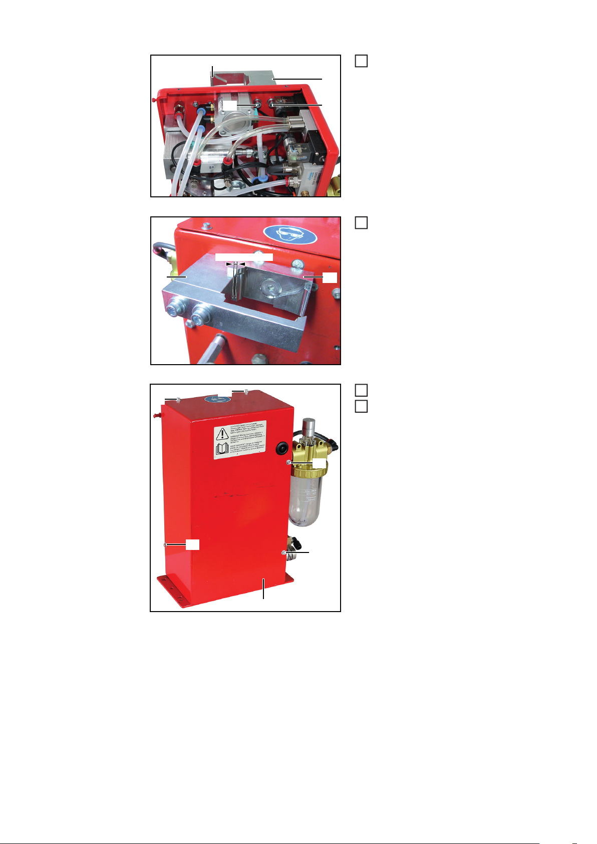
To ensure that the cleaning device is depressurized, try to briefly activate the cleaning device without the compressed air supply. To do this, proceed as follows:
Take protective measures:
1
- The cleaning cutter, cleaning brush, lifting device, gas nozzle clamping device,
wire cutter and parting-agent injection nozzle may be activated. Therefore, keep
your body, especially hands, face and hair, as well as objects and all items of
clothing, away from the aforementioned parts
- Wear hearing protection
- Wear protective goggles with side protection
Ensure that the cleaning device is disconnected from the compressed air supply
2
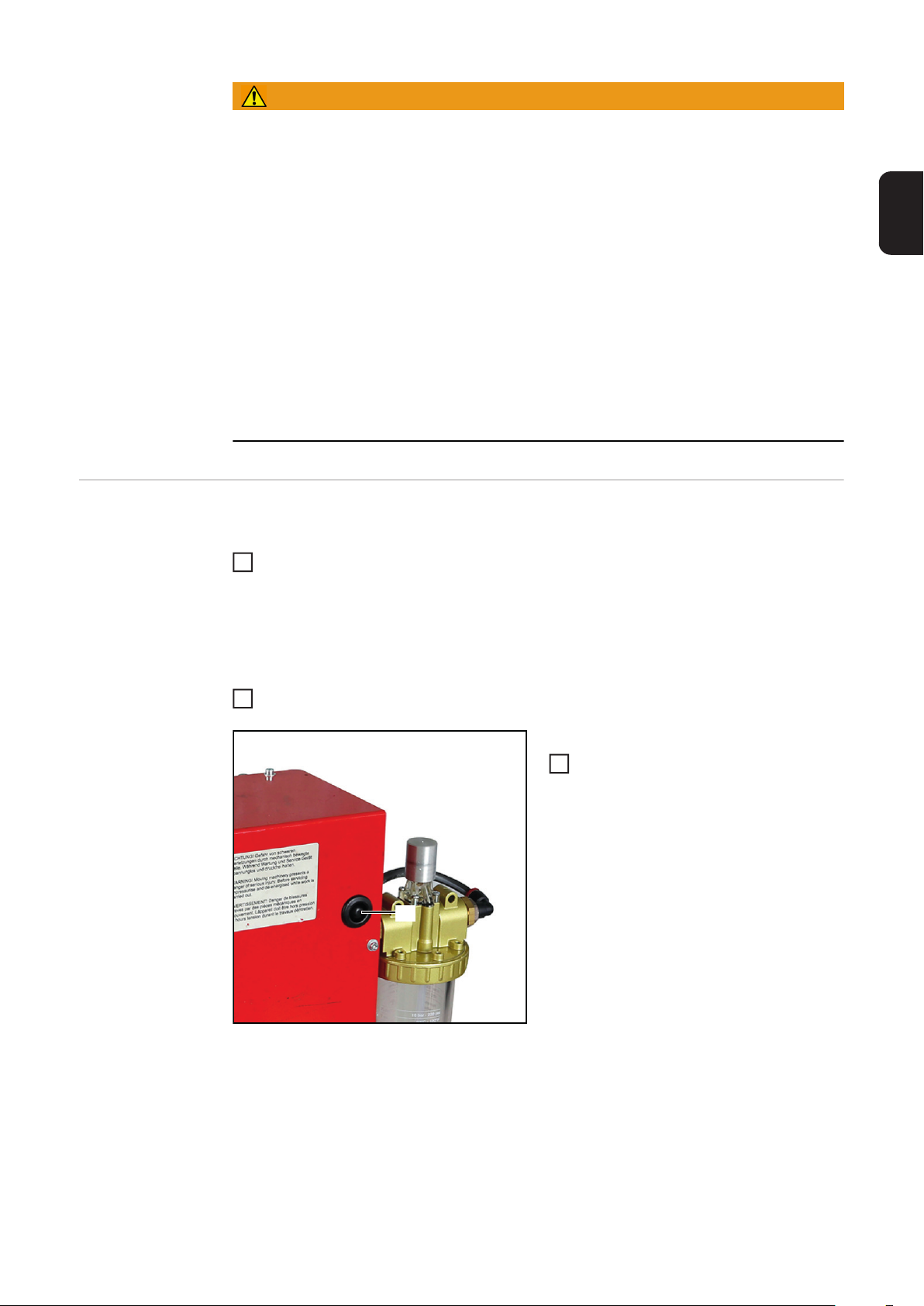
If a wire cutter is present:
Press the injection button (1) on the
3
rear side of the device for 2 s
If the injection process is not carried out,
the device is depressurized.
(1)
15
Page 16
Installing the Reamer Twin Clamping System
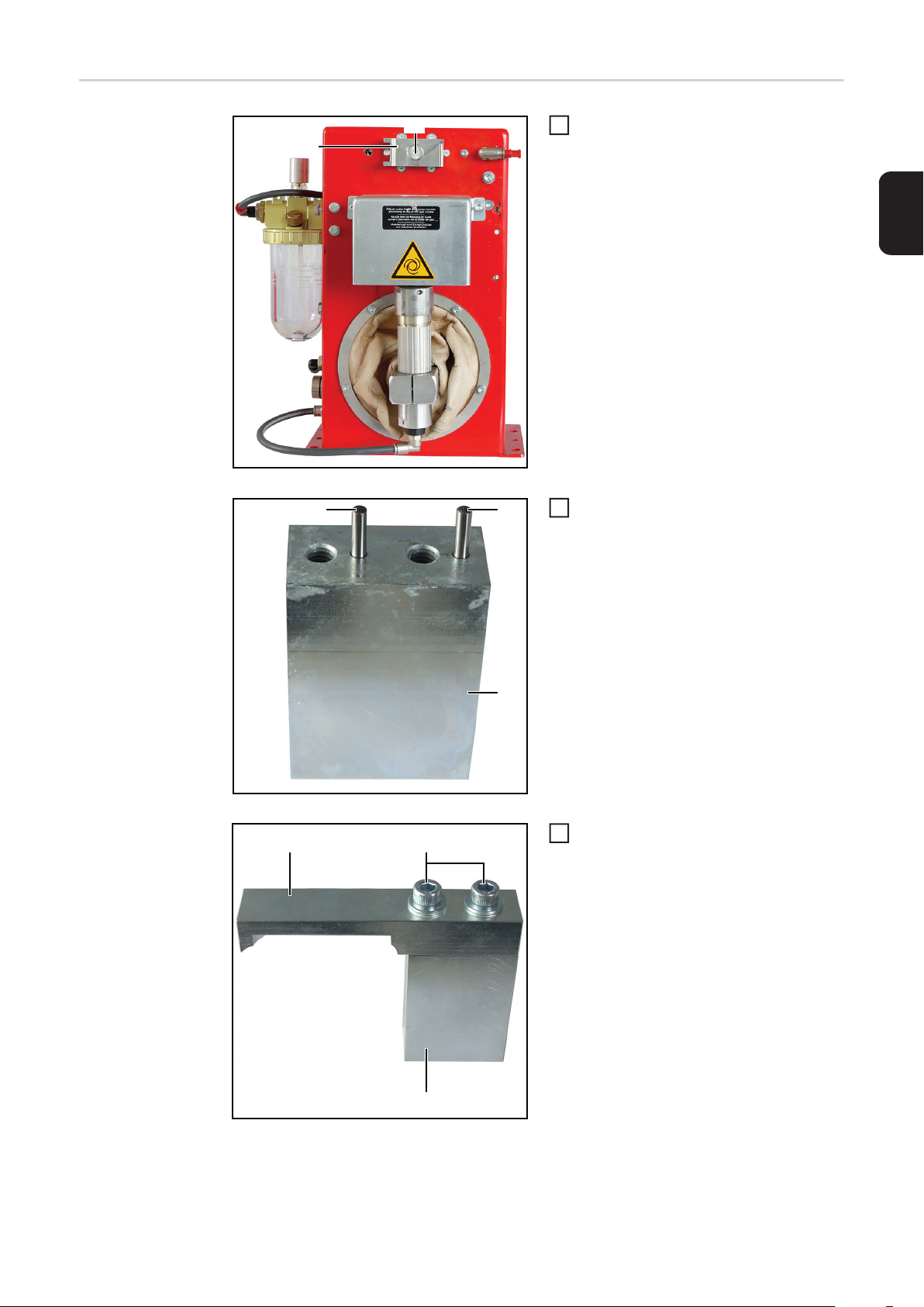
Removing Existing Clamping Device Elements
(7)
(7)
(7)
(8)
(9) (9)
(7)
(10)
(7)
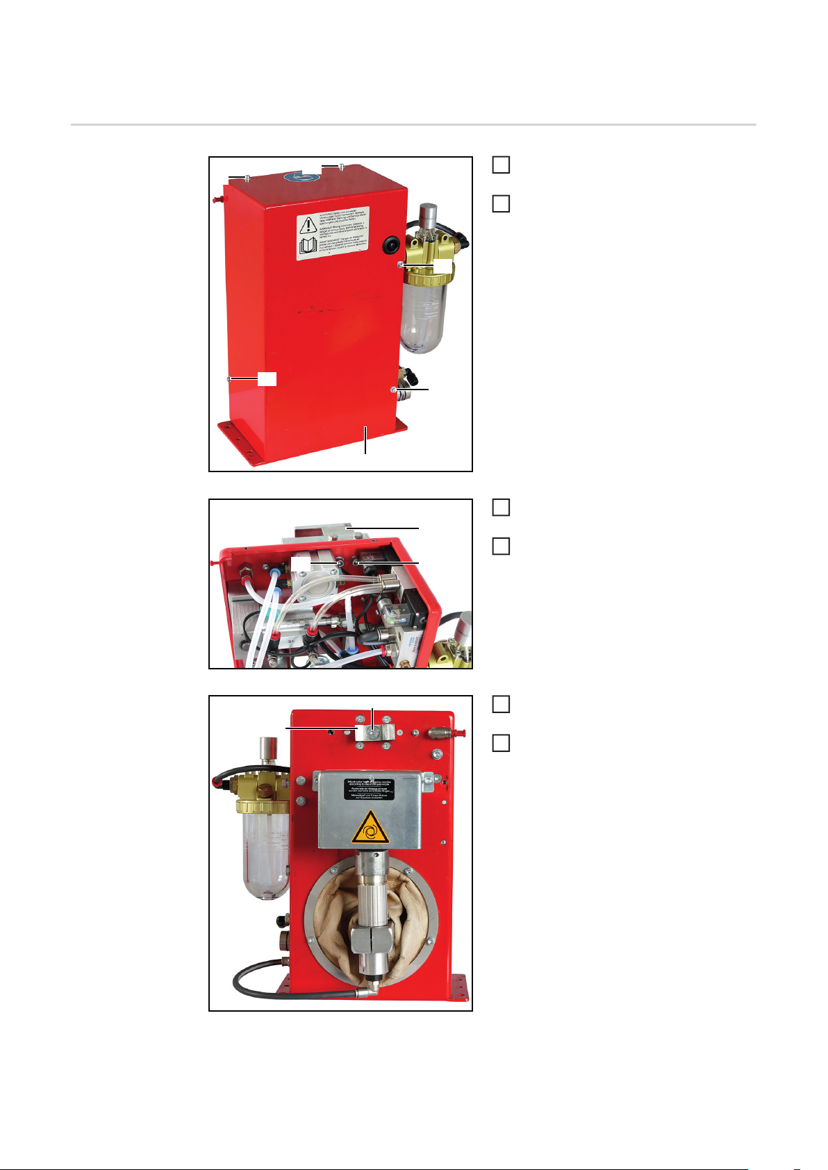
Remove 5 Allen screws (7)
1
- Wrench size 3
Remove the housing casing (8)
2
Remove 2 Allen screws (9)
3
- Wrench size 5
Remove the clamping element (10),
4
which consists of three components
that are bolted together
(12)
(11)
Remove the Allen screw (11)
5
- Wrench size 5
Remove the clamping device element
6
(12)
16
Page 17
Installing the
Reamer Twin
Clamping System
(1)
(5)
(3) (3)
Secure clamping device element 2 (5)
1
using the countersunk Allen screw
M8x25 (1)
- Wrench size 5
Insert 2 dowel pins 3x12 (3) into clam-
2
ping element 1 (4)
EN-US
(6)
(2)
(4)
(4)
Secure clamping device element 1 (4)
3
to clamping device element 3 (6)
- Using 2 Allen screws M6x25 (2),
each with a washer
- Wrench size 5
17
Page 18
(6)
(4)
(9) (9)
0,5 mm (.02 in.)
(4) (5)
Once you have secured clamping de-
4
vice elements 1 (4) and 3 (6) to each
other, fit them using Allen screws
M6x16 (9)
- Wrench size 5
Ensure that clamping device element 1
5
(4) is approximately 0.5 mm (0.02 in.)
away from clamping device element 2
(5).
(7)
(7)
(7)
(8)
(7)
(7)
Position the housing casing (8)
6
Fit the housing casing (8) using 5 Allen
7
screws M4x8 (7)
- Wrench size 3
18
Page 19

EN-US
19
Page 20

FRONIUS INTERNATIONAL GMBH
Froniusstraße 1, A-4643 Pettenbach, Austria
E-Mail: sales@fronius.com
www.fronius.com
Under www.fronius.com/contact you will find the addresses
of all Fronius Sales & Service Partners and locations
 Loading...