

Page 1

/ Perfect Welding / Solar Energy / Perfect Charging
Trolley/rack TP06
Operating Instructions,
Maintenance
EN
Trolley
42,0426,0140,EN V03 - 03022017
Page 2

Page 3

Dear reader,
Introduction
Thank you for the trust you have placed in our company and congratulations on buying
this premium Fronius product. These instructions will help you familiarise yourself with
the product. Reading the instructions carefully will enable you to learn about the many
dierent features it has to oer. This will allow you to make full use of its advantages.
Please also note the safety rules to ensure greater safety when using the product.
Careful handling of the product will repay you with years of safe and reliable operation.
These are essential prerequisites for excellent results.
3
Page 4

4
Page 5

Inhaltsverzeichnis
General information 7
About this document ........................................................................................................................................ 9
Function of this document .......................................................................................................................... 9
Explanation of safety symbols .................................................................................................................... 9
Qualied technicians .................................................................................................................................. 9
Copyright .................................................................................................................................................... 9
General .......................................................................................................................................................... 10
Device concept ......................................................................................................................................... 10
Application area ....................................................................................................................................... 10
Notes regarding the marking of control elements and connections ......................................................... 10
Scope of supply ........................................................................................................................................ 10
Safety 11
Operational reliability and tips for the user .................................................................................................... 13
Proper use ............................................................................................................................................... 13
Improper use ............................................................................................................................................ 13
Conversions or modications ................................................................................................................... 13
Operating instructions .............................................................................................................................. 13
Instructions ............................................................................................................................................... 14
Third-party and untrained personnel ........................................................................................................ 14
Distribution of keys ................................................................................................................................... 14
Mains voltage adaptation ......................................................................................................................... 14
Securing electrical systems ...................................................................................................................... 15
Protection device for power sources ........................................................................................................ 15
Local regulations ...................................................................................................................................... 15
Replacement parts, wearing parts and auxiliary materials ....................................................................... 15
Details when ordering spare parts ........................................................................................................... 15
Safety features .............................................................................................................................................. 16
General.....................................................................................................................................................16
Lockable front wheels .............................................................................................................................. 16
Power source safety device in the trolly ................................................................................................... 17
Warning notices axed to the trolly .........................................................................................................18
Description of the warning notices ........................................................................................................... 19
Residual risks ................................................................................................................................................ 20
General.....................................................................................................................................................20
Description of residual risks ..................................................................................................................... 20
Description of the system 21
Transporting and storing ................................................................................................................................23
Handling and transporting items .............................................................................................................. 23
After delivery ............................................................................................................................................ 24
Temporary storage ...................................................................................................................................24
Transporting and setting up ......................................................................................................................24
Technical description ..................................................................................................................................... 27
Description of trolly ................................................................................................................................... 27
Trolly data ................................................................................................................................................ 28
Dimensions...............................................................................................................................................28
5
Page 6

Commissioning, operation 29
Commissioning .............................................................................................................................................. 31
Properties of the installation site .............................................................................................................. 31
Stability ..................................................................................................................................................... 31
Energy connections .................................................................................................................................. 32
Operation ....................................................................................................................................................... 33
Fitting the power sources ......................................................................................................................... 33
Safety ....................................................................................................................................................... 35
Connecting the grounding (earthing) cable .............................................................................................. 35
Checking the connections ........................................................................................................................ 35
Switching on the trolly ............................................................................................................................. 35
Troubleshooting, maintenance and disposal 37
Troubleshooting ............................................................................................................................................. 39
General.....................................................................................................................................................39
Safety ....................................................................................................................................................... 39
Basic requirements for the system to work .............................................................................................. 39
Maintenance .................................................................................................................................................. 40
Safety ....................................................................................................................................................... 40
Maintenance engineers ............................................................................................................................ 40
Stopping the system ................................................................................................................................. 40
Securing against unexpected movements ............................................................................................... 40
Switching o the system and ensuring it cannot be switched back on again ........................................... 40
Maintenance record ................................................................................................................................. 41
Maintenance intervals and procedures .................................................................................................... 41
Disassembly and disposal ............................................................................................................................. 42
Personnel ................................................................................................................................................. 42
Disassembling the system ....................................................................................................................... 42
Disposal of components ........................................................................................................................... 42
Appendix 43
Replacement parts ........................................................................................................................................ 45
Replacement parts, wearing parts and auxiliary materials ....................................................................... 45
Ordering details ........................................................................................................................................ 45
Trolly replacement parts ........................................................................................................................... 46
Trolly/rack circuit diagram ........................................................................................................................47
6
Page 7

General information
7
Page 8

8
Page 9

About this document
Function of this
document
Explanation of
safety symbols
These operating instructions tell you how to commission and operate the
trolly/rack TP06 in conjunction with the installed system components. Look after the operating instructions carefully; they must always be to hand at the location where the trolly
is being used. They can be used as a reference should any operational or functional
problems occur in the future.
DANGER! Indicates immediate and real danger. If it is not avoided, death or
serious injury will result.
WARNING! Indicates a potentially dangerous situation. Death or serious injury
may result if appropriate precautions are not taken.
CAUTION! Indicates a situation where damage or injury could occur. If it is not
avoided, minor injury and/or damage to property may result.
NOTE! Indicates a risk of awed results and possible damage to the equip-
ment.
IMPORTANT! Indicates tips for correct operation and other particularly useful information. It does not indicate a potentially damaging or dangerous situation.
Qualied
technicians
Copyright
Special care is required if you see any of the symbols shown.
These operating instructions are designed for trained technicians or persons with practi-
cal welding experience. Personnel must be trained through veriable regular instruction.
Maintenance and repair of the trolly/rack may only be carried out by trained technicians
and in compliance with the specied maintenance activities and maintenance
intervals. The manufacturer accepts no responsibility for damages caused by insucient
knowledge of how to use the product.
Copyright of these operating instructions remains with Fronius International GmbH.
Text and illustrations were accurate at the time of printing. We reserve the right to make
changes. The contents of the operating instructions shall not provide the basis for any
claims whatsoever on the part of the purchaser.
9
Page 10

General
Device concept
Application area
The trolly/rack TP06 has been specially
developed for the TP 2500 power source.
The carriage is designed to hold six
TP 2500 power sources.
There are two shelves on the trolly/rack
TP06, which can accommodate up to three
power sources each. The copper busbars
installed on the trolly each allow up to
three power sources to be connected
to a common earthing point.
Trolly/rack TP06
NOTE! Connecting both copper busbars is not permitted as this could cause
an overload on the connected grounding (earthing) cable.
The trolly/rack TP06 is suitable for use in any situation where a high degree of exibility
and mobility is required of the welding system.
The trolly/rack TP06 can be used for the following Fronius products:
- TP 2500 power sources
Notes regarding
the marking of
control elements
and connections
Scope of supply
Care has been taken when writing the operating instructions to ensure that identical
control elements and connections are identied in the same way.
Examples:
- If the grounding (earthing) connection is marked with (A) on the power source, the
grounding (earthing) connection is also marked with (A) on the carriage.
The scope of supply for the trolly/rack TP06 comprises:
- the trolly/rack TP06
- six short 35mm² grounding (earthing) cables, length 45cm (for connecting the power
sources to the ground bars)
Not included in the scope of supply:
- two 95mm² earth leads, three metres with M12 cable lugs tted at both ends (for
connecting the trolly to the ground potential)
10
Page 11

Safety
11
Page 12

12
Page 13

Operational reliability and tips for the user
Proper use
Improper use
The trolly/rack TP06 is intended for transporting power sources and supplying these
same power sources with power. Any other use shall be deemed improper and the manufacturer will assume no responsibility for any resulting damages.
Proper use also includes:
- complying with all the instructions in the operating instructions
- carrying out all maintenance work at the stipulated intervals
- keeping a service book with the most important data (date, operator, activities carried
out)
- using the spare parts stipulated by Fronius
- using this document in conjunction with the operating instructions for the integrated
system components (power sources, wire-feed units, etc.)
- Operating electrical devices that have been approved
(e.g drills, angle grinder,etc.)
IMPORTANT! The trolly/rack TP06 must only be used for its intended purpose, and must
always be kept in perfect condition in terms of its safety features. This is the only way to
ensure that the trolly remains operationally reliable.
Any use of the trolly other than for its intended purpose shall be deemed improper use.
This includes:
- Transporting people
- Hoisting processes (hoisting, manoeuvring of loads) --> crane activities
- Using as ascent aids
- Use outside of the permitted technical operating limits (e.g. max. permitted load
exceeded)
- Use in hazardous areas
Conversions or
modications
Operating
instructions
If the user carries out any unauthorised conversion or modication of the trolly, any liability or warranty from the manufacturer is invalidated. The electromagnetic characteristics
of the trolly can be adversely aected by any kind of addition or modication. No modications or additions to the trolly should the refore be undertaken without rst consulting
the manufacturer and receiving written approval.
The operating instructions help you to use the trolly safely and eciently, and must therefore be to hand at all times.
- The operating instructions must always be kept near the trolly.
- Clearly mark the place where the instructions are kept
- Ensure that all persons using the trolly know where the operating instructions are
located.
- The operating instructions will only be able to help you in the event of a problem if
they are at hand!
IMPORTANT! The manufacturer shall not be liable for any damage that arises from
failure to observe the operating instructions.
13
Page 14

Instructions The operator must inform all people working with the trolly about the following before
starting work:
- the theoretical and practical aspects of operating the trolly
- the safety regulations applicable to the trolly.
IMPORTANT! The duty to instruct applies in particular to those who only occasionally
work with the trolly. (e.g. during set-up, maintenance, etc.)
Third-party
and untrained
personnel
Distribution
of keys
Do not allow third-party or untrained personnel unsupervised access to the trolly.
- Visitors or untrained personnel may only approach the trolly when accompanied by
trained personnel.
- Display a "No unauthorised access" sign at appropriate locations in the access areas
to the trolly.
- Ensure that the trolly is only operated under supervision and is locked when the op-
erator leaves.
Access by unauthorised persons must be prevented to avoid the risk of serious accidents.
The following components can be locked:
- Main switch on the trolly
IMPORTANT! The operator must provide a padlock to lock the main switch.
NOTE! The keys may only be given to persons who are responsible for, and
trained in, the relevant areas. If unauthorised persons gain access to the
trolly then lethal hazards can arise that will aect everyone in the vicinity.
The following measures regarding the whereabouts of keys must be put in place by the
operator:
- Keep a record of who was given which key and when
- Keep unused keys locked away in a suitable place. (key cabinet)
- Instruct personnel that a trolly must be locked even if it is unsupervised for only a
short time, and the keys stored away securely by those with responsibility.
- Check regularly to ensure that these measures are being implemented.
Mains voltage
adaptation
If adaptations to mains voltages are necessary, an electrically isolated 3-phase transformer must be used. An autotransformer is NOT SUITABLE in this situation. The elec-
trical connection specications on the trolly and/or in the operating instructions must be
observed.
- Check the supply voltage before starting up the trolly
14
Page 15

Securing
electrical
systems
- Only trained technicians may access the electrical working areas and any access by
unauthorised persons must be prevented.
- Display a warning sign in a suitable location if not already present.
- Cordon o electrical working areas during assembly, repair, maintenance, etc. to
ensure that no unauthorised persons can enter.
Protection device
for power sources
Local
regulations
Replacement
parts, wearing
parts and
auxiliary
materials
The power sources in the trolly are secured using a protection device that prevents them
from inadvertently falling out. This protection device must be xed to the power sources
whenever the trolly is in use. If a protection device is removed for main-tenance or set-up
work, it must be retted before the trolly is used again.
In some countries, local statutory regulations may apply that are not included in these
operating instructions. It is the duty of the operator to be aware of and comply with any
local statutory regulations. This relates primarily to regulations concerning:
- Accident prevention
- Machine safety
- Protection of personnel (protective equipment)
- Environmental protection
- Electrical system
Using replacement parts and wearing parts from third parties may pose resulting risks.
Use Fronius original replacement parts only.
The manufacturer cannot accept any liability for damage resulting from the use of
replacement or wearing parts or auxiliary materials that are not approved by the manufacturer.
Details when
ordering spare
parts
NOTE! Only trained technicians may change parts and may only do so after
having read the installation and dismantling instructions supplied.
When ordering replacement parts, you should provide the following data:
- Exact designation of the replacement part
- Corresponding item number as per spare parts list
- Model name of the machine (see rating plate)
15
Page 16

Safety features
General
Lockable front
wheels
WARNING!
Operating the equipment incorrectly can cause serious injury and damage.
Do not use the functions described here until you have thoroughly read
and understood the following documents:
- these operating instructions
- all operating instructions for the system components
Safety devices must not be removed, bypassed or changed, unless this is necessary for
the purposes of maintenance, repair or retrotting.
In this case, immediate reinstallation and testing must be carried out by technicians with
the appropriate training before the trolly is used again.
WARNING!
Risk of injury and damage caused by not operating the braking device
For your personal safety, ensure that the lockable front wheels are locked and
remain so for as long as you are in the vicinity of the trolly.
Lockable wheels
16
Page 17

Power source
safety device in
the trolly
WARNING!
Risk of injury and damage caused by not securing the power sources
using the safety device
For your personal safety, ensure that the power sources are secured in the
trolly so that they do not fall out inadvertently.
Mounting rails for the power sources.
17
Page 18

Warning notices
axed to the
trolly
The plant operator must keep all warning and information signs displayed on the trolly
in a visible position and in legible condition. Such signs must not be removed or painted
over. Damaged or illegible signs must be replaced with new ones immediately. If a sign
has been destroyed and you are uncertain about what it used to look like, get in touch
with our customer service.
Failure to mark danger areas represents a risk of serious or fatal injury to all personnel
working in the vicinity of the system.
Warning and information signs should therefore be cleaned regularly.
Warning notices axed to the trolly
18
Page 19

Description of the
warning notices
WARNING!
Risk of severe injury or damage from incorrect lifting and transport processes.
Incorrect processes and unsuitable or incorrect devices can cause
severe injury and/or damage.
- The lifting lugs must only be used according to the instructions
from the manufacturer in order to transport the trolly safely.
- The correct load-carrying equipment must be used for transport
and installation.
Item number: 38,0008,0064 (DM 50mm)
DANGER!
Risk of fatal injury from dangerous electrical voltage.
The areas bearing this symbol contain parts under high voltage.
An electric shock can be fatal.
- The areas concerned must not be opened by unauthorised
personnel!
Item number: 38,0008,0029 (SL 100mm)
Item number: 38,0008,0028 (SL 200 mm)
19
Page 20

Residual risks
General
Description of
residual risks
Despite all the technical safety features and measures implemented to reduce risk, using
the trolly still involves a certain degree of risk. In addition to instruction from
FRONIUS experts, the warning signs on the trolly must be observed at all times. The following residual risks should be considered when the trolly used in the modes described.
- Risk of tripping/slipping near the trolly
- Risk of tripping/slipping on transport routes, in loading and unloading areas
- Risk of tripping over materials kept near the trolly
- Risk of unexpected trolly movements if the brakes are not properly applied or
released
- Hazards when working on the power supply
20
Page 21

Description of the system
21
Page 22

22
Page 23

Transporting and storing
Handling and
transporting
items
CAUTION!
Risk of damage due to incorrect handling of transport boxes.
The system parts are secured for transport and delivered in boxes. These have
various transport notices axed to them.
- Observe the transport notices on the packaging or boxes.
Symbol Explanation
Protect from moisture! The shipping item must be kept dry.
Keep upright during transport! Always store and transport shipping
items with the arrows pointing upwards. Shipping items must not be
laid on their side or upside-down. If this requirement is not observed,
the goods may be damaged in transit.
When lifting and transporting a shipping item, note its centre of gravity. When lifting, always hold the item as close to this point as possible. This will prevent it from tipping over unexpectedly.
Fragile! The shipping item must always be handled with care.
Attach here! The lifting tackle (lashing chain, hoisting belt) is to be
attached at the indicated points.
Avoid touching packages with this symbol when the relative humidity
is low, especially if wearing insulating footwear or the oor is non-conductive. Low relative humidity is most common on warm, dry summer
days and very cold winter days.
Lifting point! Only lift the shipping item or machine from points designated with this symbol.
23
Page 24

After delivery
Inspect the transport packaging (container, box) for damage.
IMPORTANT! Fronius International GmbH must be notied immediately of any
damage to the packaging. This will expedite the replacement of any damaged parts.
CAUTION!
Risk of damage from build-up of condensation.
If parts are not unpacked immediately after delivery, moisture can form on or
inside the parts (condensation). This can lead to serious damage as a result of
the corrosion of parts or to short circuits in electronic/electrical equipment.
- Ensure that parts are at room temperature before commissioning.
- Do not attempt to accelerate this process by exposing the parts to a direct
heat source.
- If condensation occurs, the parts must not be used until they have dried out
completely (wait ve hours). .
Temporary
storage
Transporting and
setting up
Store the parts in a sheltered place that is dry and free from dust.
Storage conditions:
- Never tip
- Avoid heavy impact
- Put some wood down rst if storing on hard ground.
If storing for more than three months:
- Oil exposed machine parts every month
- Protect the system from dust and moisture
The total weight of the trolly and system components can be found in the "Trolly data"
section. The load-carrying equipment used must be designed for the weight of the trolly.
Check its maximum load before lifting the system.
WARNING!
Risk of serious injury from standing under suspended loads.
Hoisting, rigging and carrying equipment may be damaged. Falling loads can
cause death or serious injury. Body parts can be crushed, fractured or otherwise injured.
- Never stand under a freely suspended load.
- Make absolutely certain that all attachments are xed and secure before
moving the trolly.
- Only use lifting gear with sucient lifting capacity
- Never use damaged lifting gear
- Do not knot the carrying equipment or lay it over sharp edges
- Always use carrying equipment of the same length
- Move the trolly carefully, avoiding sudden movements
- Set the trolly down carefully
- Use a specialist rm to move the trolly if required.
24
Page 25

Transporting and
setting up
(continued)
WARNING!
Risk of serious injury and damage from incorrect lifting and transportation procedures.
Incorrect procedures and unsuitable or damaged devices can cause serious
injuries and/or damage.
- Observe national regulations when transporting; lifting equipment, ground
conveyors and load-carrying equipment must call conform to specications
- Use the correct load-carrying equipment for transport and installation
- Only use the lifting lugs or lifting points (fork grooves) specied by the
manufacturer to transport the trolly safely.
- For your personal safety, wear gloves and safety footwear when moving the
trolly or system components.
CAUTION!
Risk of damage if cables are kinked or damaged.
Damaged cables can cause short circuits and consequently defects in the
system controls.
- Before lifting the trolly, ensure that cables cannot be pulled, kinked or
trapped.
Before lifting the trolly, check the following:
- Have the transport xings, such as pins and screws, been completely removed?
- Has rust or adhesive residues been removed?
- Have all connection leads been removed or properly secured?
► Use a forklift truck to lift the trolly as shown in the picture.
► Use the forklift lifting points on the machine body. These are marked with yellow
"lifting point" pictograms.
Lifting point
Trolly/rack TP06 transportation points (representative image)
25
Page 26

Transporting and
setting up
(continued)
Lifting ring lifting point
Trolly/rack TP06 transportation points (representative image)
CAUTION!
Risk of damage from lifting the trolly incorrectly
Lifting the trolly by the handle can cause damage.
- Before lifting the trolly, ensure that it has been attached by the specied lift-
ing points.
26
Page 27

Technical description
Description
of trolly
The trolly is designed to be used for transporting and storing up to six TransPocket 2500
power sources.
Due to the service-friendly design of the trolly, the individual power sources can be replaced quickly and without using any additional tools.
The insulated copper busbars (1) tted to the trolly and the short earth leads (2)
included in the scope of supply allow up to three power sources per copper busbar to be
connected to a common ground potential.
To facilitate moving the trolly from one location to the next, the trolly has a stable
hard plastic handle (3), two xed castors (4) and two lockable swivel castors (5).
In addition, the trolly features two forklift truck lifting points integrated into the
base (6) and four swivelling lifting ring holders with ring screws (7) secured to the top of
the trolly.
The trolly is equipped with a robust protective cover to protect the power sources inside.
It also features a tray area with a rubber mat (8). Four holding devices (9) prevent any
power sources in the trolly from inadvertently falling out.
6x
(7)
(2)
(1)
(4)
Technical description of the trolly
(8)
(3)
(9)
(6)
(5)
27
Page 28

Trolly data
DANGER!
Risk of fatal injury from dangerous electrical voltage.
The areas bearing this symbol contain parts that are under dangerous electrical voltages. An electric shock can be fatal.
- The distributor must not be opened by unauthorised personnel.
Weight of trolly
► Weight of trolly without power sources 90Kg
► Weight of trolly with power sources 160Kg
Fahrwagen Rack TP06
A-4600 Wels
www.fronius.com
YC:2012
3~
230/400 V
50 Hz
Type:
No.:
U
1
max. load
70 kg
1040 x 650 x 1020 mm
Welding Equipment
I1
125 A
L x W x H
8,045,531
6x16 A
weight
160 kg
Dimensions
Trolly rating plate (representative image)
Trolly/rack dimensions
28
Page 29

Commissioning, operation
29
Page 30

30
Page 31

Commissioning
Properties of the
installation site
Stability
Surface:
- level and rm
Environment:
- not outdoors
- not in a hazardous area
- not in an area of increased electrical risk (including boilers,
narrow spaces or conned areas, between or on electrically conductive parts, in
damp or hot rooms).
NOTE! The power source ventilation slot (air inlet, air outlet) is a very
important safety feature. When choosing the installation site, ensure that
the cooling air can enter and exit unhindered through the front air slot. Any
electroconductive metallic dust (e.g. from grinding work) must not be allowed
to get sucked into the power sources. The system operator must ensure that
there is a sucient circulation of air through the entire trolly.
The trolly must be used and operated in such a way that it remains stable. For example,
stability can be adversely aected by:
- Overloading
- Soft ground
- Sudden acceleration
- Working on steep slopes
To ensure the trolly remains stable when it is used and operated, the user may need to
adapt working methods to the local site conditions:
► Prevent the trolly from being moved unintentionally, e.g by a fork-lift truck.
► Prevent vibration and oscillation during operation.
Trolly stability (representative image)
≤10 Dgr
31
Page 32
Energy
connections
DANGER!
Risk of fatal injury from dangerous electrical voltage.
An electric shock can be fatal.
- The mains lead must only be connected by Fronius technicians.
The manufacturer assumes no responsibility for damage to persons or
property caused by incorrect connection by the customer.
CAUTION!
Risk of serious damage to property due to insuciently dimensioned
electrical installations.
The mains lead and its fuse protection must be rated accordingly. The technical
data shown on the rating plate applies.
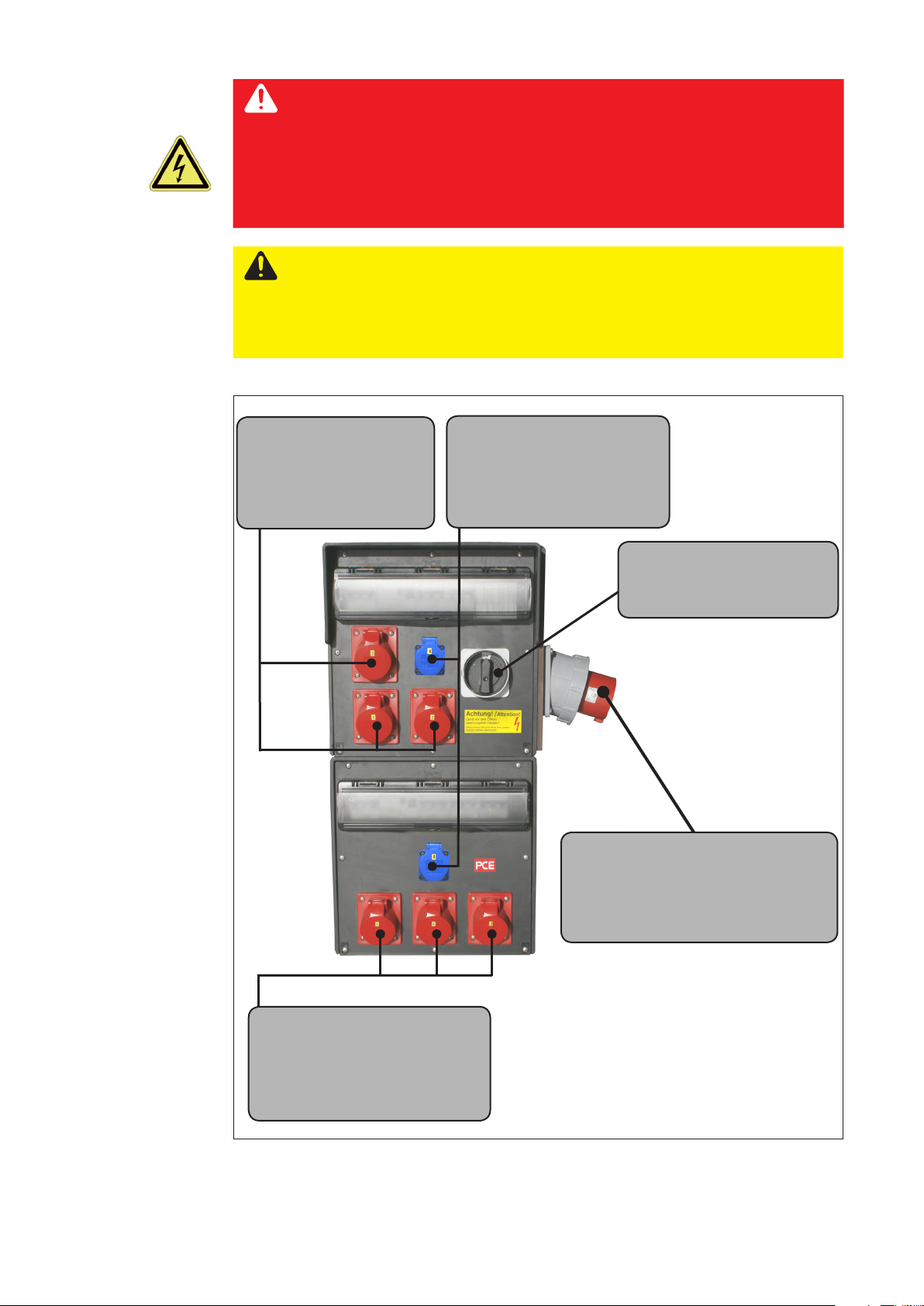
Supply:
Power sources
3 x 400 V~ / N / PE
Mains frequency: 50 Hz
Mains fuse: 16 A
Supply:
Electrical equipment
230 V~ / N / PE
Mains frequency: 50 Hz
Mains fuse: 16 A
Main switch:
switches all outgoing lines
on the distributor
Trolley mains connection:
Mains voltage: 3 x 400V~ / N / PE
Mains frequency: 50 Hz
Mains fuse: max. 125 A
Supply:
Power sources
3 x 400 V~ / N / PE
Mains frequency: 50 Hz
Mains fuse: 16 A
Trolly connections
32
Page 33

Operation
Fitting the
power sources
Dismantle the holding devices
► Undo the star screws and store them in a safe place
► Pull the holding devices out of the frame
Dismantling the holding devices
Place the power sources in the trolly
► Push the power sources into the trolly one-by-one
► Ensure that the power sources are installed the right way round (grounding (earthing)
connection on power source must be facing the copper busbars)
Placing the power sources in the trolly
33
Page 34

Fitting the
power sources
(continued)
Fix the holding devices
► Push the holding devices under the power source handles and position them in such
a way that the handles t inside the holding device recesses
Fixing the holding devices
Secure the holding devices
► Screw the holding devices back onto the trolly using the star screws removed previ-
ously
Securing the holding devices
34
Page 35

Safety
WARNING!
Incorrect operation may result in serious injury or damage.
Do not use the functions described here until you have thoroughly read and
understood the following documents:
- these operating instructions
- all the operating instructions for the system components, especially the
safety rules.
Connecting
the grounding
(earthing) cable
Only the grounding (earthing) cables supplied can be used for the trolly.
The operator is to arrange the grounding (earthing) cables for connecting the trolly to the
ground potential.
WARNING!
Fitting grounding (earthing) cables that are too small can cause serious
injury or damage.
A grounding (earthing) cable that is too small heats up to a very high tempera-
ture. This presents a risk of burns and re.
- Before commissioning, ensure that the grounding (earthing) cable used has
a cross-section of at least 95mm².
- The grounding (earthing) cable may only be connected by qualied personnel.
Checking the
connections
Switching on the
trolly
Trolly grounding (earthing) connections with the earth leads (circled) to be tted
Check all connections between the individual components before starting up
the trolly:
- Power supply
- Distributor
- Torch connections
- Grounding (earthing) connections
- Power sources
Detailed information on the assembly and connection of the individual system components can be found in the relevant operating instructions.
IMPORTANT! Ensure that the power source mains switches are switched to “OFF” when
switching on the main switch. The power sources can then be switched on. There is no
set sequence for switching on the power sources. They can be switched on in any order.
35
Page 36

36
Page 37

Troubleshooting, maintenance
and disposal
37
Page 38

38
Page 39

Troubleshooting
General
Safety
In the event of errors, note that the function of the entire system depends on many
additional components that are also potential sources of problems.
NOTE! Faults may only be corrected by qualied experts or by Fronius ser-
vice personnel.
WARNING!
An electric shock can be fatal.
Before opening the distributor:
- Move the mains switch to the "O" position
- Unplug the device from the mains
- Put up an easy-to-understand warning sign to stop anybody inadvertently
switching it back on again
WARNING!
An insucient PE conductor connection may result in serious injury or
damage.
The housing screws provide an adequate PE conductor connection for earthing
the housing.
- They must NOT be replaced by any other screws that do not provide a reliable PE conductor connection.
Basic
requirements for
the system to
work
- Connections established between separate system components
- System components are supplied with electricity and the mains voltage is as
specied.
39
Page 40

Maintenance
Safety
Maintenance
engineers
Stopping the
system
WARNING!
Risk of injury and damage during maintenance work.
Before commencing maintenance work:
- Turn the main switch on the trolly to the "0" position (OFF).
- Disconnect the trolly from the mains
WARNING!
Risk of injury and damage from incorrectly performed maintenance.
It is essential to adhere to the maintenance intervals and maintenance procedures. The manufacturer accepts no liability for any damage caused by inadequate or poorly performed maintenance.
- All maintenance work on the trolly must only be carried out by trained personnel.
The manufacturer does not provide padlocks for the trolly. The trolly operator must t a
lockable padlock on the main switch.
NOTE! The padlock key may only be given to responsible persons who are
trained in this line of work. If unauthorised persons gain access to the trolly
then lethal hazards can arise that will aect everyone in the vicinity.
Securing against
unexpected
movements
Switching o
the system and
ensuring it cannot
be switched back
on again
Before carrying out any maintenance work, ensure that the braking and holding devices
tted to the trolly are engaged. Precautions must be taken to prevent these devices from
being unintentionally undone while maintenance work is being performed.
1. Switch the main switch on the distributor to "0" (OFF).
2. Put a padlock on the following components and lock:
- Main switch on distributor
40
Page 41

Maintenance
record
The following measures must be put in place by the trolly operator:
- a service book with the most important data (date, operator, maintenance activities
carried out) must be kept
- the padlock key must be locked away in a suitable container when not needed
(key cabinet)
- personnel must be instructed to lock the system even if it is unsupervised for only a
short time. The key must be kept by a responsible individual.
- list must be kept of who was given which padlock key and when
Maintenance
intervals and
procedures
NOTE! Use a dry cleaning cloth to clean the parts.
Only use a cleaning agent if this is indicated in the maintenance procedure
for a specic part.
Item Part Procedure Interval
Grounding (earthing)
A
Check connection M
cable
Rollers and rails Clean, check position M
B
D Daily
W Weekly
M Monthly
1/2 Y Half-yearly
Y Yearly
Maintenance procedures
A
B
B
B
41
Page 42

Disassembly and disposal
Personnel
Disassembling
the system
Disposal of
components
The trolly must only be disassembled and disposed of by suitable trained personnel.
Electrical equipment:
DANGER!
Risk of fatal injury from dangerous electrical voltage.
The areas bearing this symbol contain parts that are under dangerous
electrical voltages. Electrically-charged parts (capacitors) can remained
charged for a considerable length of time after they are switched o.
An electric shock can be fatal.
Before opening control cabinets and devices:
- Move the mains switch to the "O" position
- Switch o all supply leads and unplug them from the mains
- Wait for at least 10 minutes (to allow capacitors to discharge)
- Put up an easy-to-understand warning sign to stop anybody inadvertently
switching it back on again
- Check that the system is no longer live
- Carry out earthing and short-circuiting
WARNING!
Danger of environmental damage
Incorrect disassembly and disposal of the separate system components can
result in serious environmental damage.
- The separate system components must only be disposed of by
appropriately qualied personnel.
Ensure that:
- all trolly components and electrical parts are separated according to type and disposed of properly
- the consumables used are sorted and separated according to their properties
NOTE! If you have any further questions about disposal/recycling, please
contact the manufacturer.
42
Page 43

Appendix
43
Page 44

44
Page 45

Replacement parts
Replacement
parts, wearing
parts and
auxiliary
materials
Ordering
details
Using replacement parts and wearing parts from third parties may pose resulting risks.
Use Fronius original replacement parts only.
The manufacturer cannot accept any liability for damage resulting from the use of
replacement or wearing parts or auxiliary materials that are not approved by the manufacturer.
NOTE! Only trained technicians may change parts and may only do so after
having read the installation and dismantling instructions supplied.
When ordering spare parts:
- use the specied drawing number, which is noted in the spare parts list.
- If there is noted an article number too, order the part with the article number.
You should also provide the following data:
- Exact designation of the spare part
- Model name of the device
- Serial number (shown on the rating plate)
45
Page 46

Trolly
replacement
parts
,,
,,
,,
Trolly/rack TP06 replacement parts
Article number Drawing number Description
BW8.0956.0001 58-0956-0001 Fixing bracket
58.0956.0002 58-0956-0002 Copper busbar
48.0007.0233 68-0300-0289 Swivel castor with stop-x
48.0007.0234 68-0300-0290 Swivelling ring screw
48.0007.0235 68-0300-0291 Bow handle
48.0007.0236 68-0300-0292 Star grip VCT.32 B-M6
38.0005.0157 68-0800-0170 Busbar holder 2-pin
44,0001,0105 Z0015198 Star lock Ø25mm
44,0001,0042 Z0018664 Plastic trolly wheel 250mm
58.0069.0313 58-0069-0313 rubber mat 3x250x300
46
Page 47

FI 63A 4p
30mA
LS 63A 3pC
LS 16A 3pC
CEE 16A
5p 400V~
Stecker
CEE 125A
5p 400V~
LS 16A 3pC
CEE 16A
5p 400V~
LS 16A 3pC
CEE 16A
5p 400V~
FI 63A 4p
30mA
LS 63A 3pC
LS 16A 3pC
CEE 16A
5p 400V~
LS 16A 3pC
CEE 16A
5p 400V~
LS 16A 3pC
CEE 16A
5p 400V~
Stromlaufschema
5-8
5-8
1-4
1-4
HS 125A
3p
LS 16A 1pC
LS 16A 1pC
SSD
230V~
SSD
230V~
Trolly
replacement
parts
(continued)
Article number Description
38,0100,0302 Short earth lead TP06
Trolly/rack circuit
diagram
47
Page 48

FRONIUS INTERNATIONAL GMBH
TechSupport Automation
www.fronius.com
www.fronius.com/addresses
48
 Loading...