

Page 1

Operating
Instructions
RI FB PRO/i TWIN Controller
RI MOD/i CC ProfiNet
DE
EN-US
Bedienungsanleitung
Operating instructions
42,0410,2449 011-06022023
Page 2

Page 3

Inhaltsverzeichnis
Allgemeines 4
Sicherheit 4
Anschlüsse und Anzeigen 4
Eigenschaften der Datenübertragung 6
Systemreaktionen bei Kommunikationsproblemen 7
Konfigurationsparameter 7
Vergabe der IP-Adresse des Busmoduls 8
Vergabe der IP-Adresse des Busmoduls 8
IP-Adresse des Busmoduls anzeigen 8
IP-Einstellungen und Gerätenamen löschen 8
Prozessdaten-Breite des Busmoduls einstellen 10
Prozessdaten-Breite des Busmoduls einstellen 10
Ein- und Ausgangssignale 11
Datentypen 11
Verfügbarkeit der Eingangssignale 11
Eingangssignale (vom Roboter zur Stromquelle) 11
Wertebereich Working mode 18
Wertebereich Processline selection 18
Wertebereich Operating mode TWIN System 19
Wertebereich Documentation mode 19
Wertebereich Process controlled correction 19
Verfügbarkeit der Ausgangssignale 20
Ausgangssignale (von der Stromquelle zum Roboter) 20
Zuordnung Sensorstatus 1-4 25
DE
3
Page 4
Allgemeines
1234567
8
Sicherheit
WARNUNG!
Gefahr durch Fehlbedienung und fehlerhaft durchgeführte Arbeiten.
Schwere Personen- und Sachschäden können die Folge sein.
Alle in diesem Dokument beschriebenen Arbeiten und Funktionen dürfen
▶
nur von technisch geschultem Fachpersonal ausgeführt werden.
Dieses Dokument vollständig lesen und verstehen.
▶
Sämtliche Sicherheitsvorschriften und Benutzerdokumentationen dieses
▶
Gerätes und aller Systemkomponenten lesen und verstehen.
WARNUNG!
Gefahr durch elektrischen Strom.
Schwere Personen- und Sachschäden können die Folge sein.
Vor Beginn der Arbeiten alle beteiligten Geräte und Komponenten ausschal-
▶
ten und vom Stromnetz trennen.
Alle beteiligten Geräte und Komponenten gegen Wiedereinschalten sichern.
▶
WARNUNG!
Gefahr durch unplanmäßige Signalübertragung.
Schwere Personen- und Sachschäden können die Folge sein.
Über das Interface keine sicherheitsrelevanten Signale übertragen.
▶
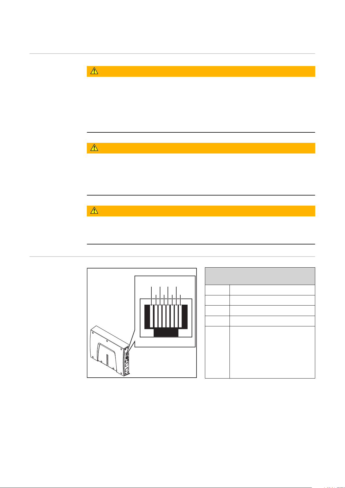
Anschlüsse und
Anzeigen
Pin-Belegung RJ 45 ProfiNet Anschluss
1 TD+
2 TD-
3 RD+
6 RD-
4,5,7,8Normalerweise nicht ver-
wendet; um die Signalvollständigkeit sicherzustellen, sind diese Pins miteinander verbunden und enden
über einen Filterkreis am
Schutzleiter (PE).
RJ 45 ProfiNet Anschluss
4
Page 5
21
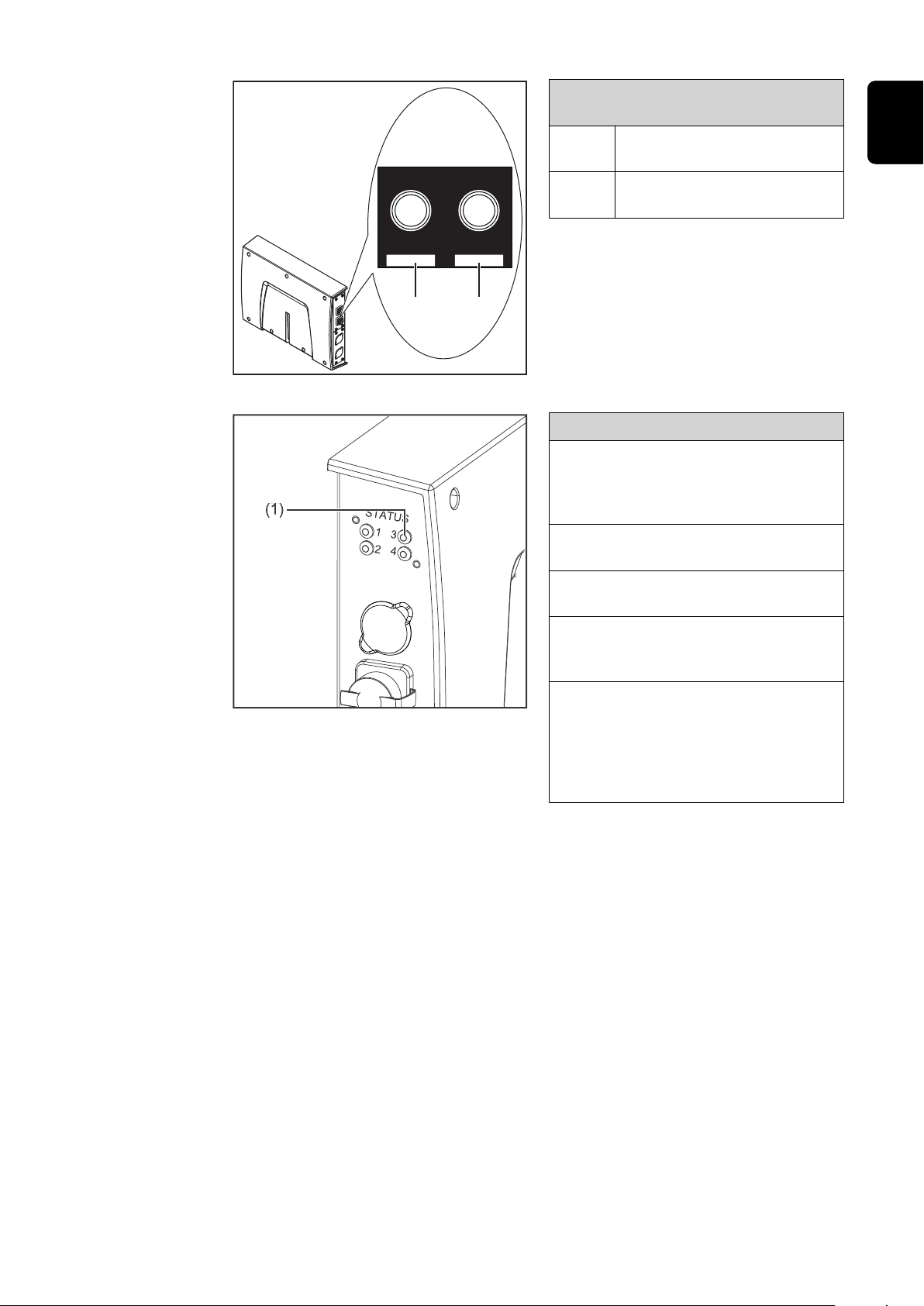
Fiber Optic (FO) Anschluss
Pin-Belegung Fiber Optic (FO) Anschluss
1 Optisches Signal vom Any-
bus CompactCom Modul
2 Optisches Signal vom Any-
bus CompactCom Modul
(1) LED MS - Modulstatus
Aus:
keine Versorgungsspannung / Modul
im Setup- oder Initialisierungs-Modus
Leuchtet grün:
normaler Betrieb
DE
LED MS - Modulstatus
Blinkt grün (einmal):
Diagnoseprozess läuft
Leuchtet rot:
Ausnahmezustand, schwerer Fehler, ...
Leuchtet abwechselnd rot und grün:
Firmwareupdate. Während des Updates das Modul nicht von der Spannungsversorgung trennen - dies
könnte Schäden am Modul zur Folge
haben!
5
Page 6

LED NS - Netzwerkstatus
(2) LED NS - Netzwerkstatus
Aus:
Offline; keine Versorgungsspannung
oder keine Verbindung mit IO Controller
Leuchtet grün:
Online (RUN); Verbindung mit IO
Controller hergestellt, IO Controller
in Betrieb
Blinkt grün (einmal):
Online (STOP); Verbindung mit
IO Controller hergestellt, IO Controller nicht in Betrieb, IO-Daten
fehlerhaft, IRT-Synchronisation
nicht fertiggestellt
Blinkt grün (dauerhaft):
Von Engineering-Tools verwendet,
um den Netzwerk-Knoten zu identifizieren
Leuchtet rot:
das Modul hat einen schweren internen Fehler festgestellt
Eigenschaften
der Datenübertragung
Blinkt rot (einmal):
Stationsname nicht gesetzt
Blinkt rot (zweimal):
IP-Adresse nicht gesetzt
Blinkt rot (dreimal):
Konfigurationsfehler; erwartete
Identifikation stimmt nicht mit der
tatsächlichen Identifikation überein
Übertragungstechnik:
Ethernet
Medium:
Bei der Auswahl der Kabel, Stecker und Abschluss-Widerstände ist die Profinet Montagerichtline für die Planung und Installation von Profinet Systemen
zu beachten.
Seitens Hersteller wurden die EMV-Tests mit dem Kabel IEC-C5DD4UGG0150A20A20-E durchgeführt.
Seitens Hersteller wurden die EMV-Tests mit einer Buszykluszeit von 32ms
durchgeführt.
Übertragungs-Geschwindigkeit:
100 Mbit/s, Full-Duplex-Mode
Busanschluss:
Ethernet RJ45 / SCRJ (Fiber Optic)
6
Page 7

Systemreaktionen bei Kommunikationsproblemen
Die Eingangssignale (vom Roboter zur Stromquelle) werden auf 0 zurückgesetzt,
wenn:
die Kommunikation unterbrochen wird (Kabelbruch, ....)
-
der IO Controller in den Betriebszustand STOP wechselt
-
ein Submodul einen IOPS-Status als BAD meldet
-
Dadurch wird beispielsweise das Signal Robot ready auf 0 gesetzt und die laufende Schweißung gestoppt.
DE
Konfigurationsparameter
Bei einigen Robotersteuerungen kann es erforderlich sein die hier beschriebenen
Konfigurationsparameter anzugeben, damit das Busmodul mit dem Roboter
kommunizieren kann.
Parameter Wert
Device ID 0380
Vendor ID 01B0
hex
hex
(896
(432
) Fronius Twin ProfiNet 2-Port
dez
) Fronius International GmbH
dez
Station Type fronius-fb-pro-twin-pn-2p
Die folgenden Parameter geben Detailinformationen über das Busmodul. Auf die
Daten kann durch den Profibus-Master mittels azyklischer Lese/Schreib-Dienste
zugegriffen werden.
Parameter Wert
IM Manufacturer ID 01B0
hex
(432
) Fronius International GmbH
dez
IM Order ID 4.044.044 (Kupfer/Lichtwellenleiter)
IM Revision Counter 0
IM Profile ID F600
IM Profile Specific
hex
0004
(0
hex
hex
)
dez
(62976
(4
dez
) Generic Device
dez
) No profile
Type
IM Version 0101
IM Supported 0000
hex
hex
(257
(0
)
dez
) IM0 supported
dez
7
Page 8

Vergabe der IP-Adresse des Busmoduls
Vergabe der IPAdresse des
Busmoduls
IP-Adresse des
Busmoduls anzeigen
Bei ProfiNet wird die Vergabe der IPAdresse, der Subnet-Mask und des Default-Gateways vom Master durchgeführt. Auch ein Gerätename wird
dem Interface vom Master zugewiesen.
Deshalb kann die IP-Adresse nicht
über den DIP-Schalter eingestellt werden.
Die Kommunikation läuft über die vom
Master zugewiesene IP-Adresse.
Die vom Master vergebene IP-Adresse des Busmoduls kann auf der Website der
Stromquelle (SmartManager) eingesehen werden. Hierzu wie nachfolgend angeführt vorgehen.
IP-Adresse der verwendeten Stromquelle notieren:
Am Bedienpanel der Stromquelle „Voreinstellungen“ auswählen
1
Am Bedienpanel der Stromquelle „System“ auswählen
2
Am Bedienpanel der Stromquelle „Information“ auswählen
3
Angezeigte IP-Adresse notieren (Beispiel: 10.5.72.13)
4
IP-Einstellungen
und Gerätenamen löschen
Website der Stromquelle im Internetbrowser aufrufen:
Computer mit dem Netzwerk der Stromquelle verbinden
5
IP-Adresse der Stromquelle in die Suchleiste des Internetbrowsers eingeben
6
und bestätigen
Standard-Benutzernamen (admin) und Passwort (admin) eingeben
7
Website der Stromquelle wird angezeigt
-
IP-Adresse des Busmoduls anzeigen:
Auf der Website der Stromquelle den Reiter „RI FB PRO/i TWIN Controller“
8
auswählen
Bei Punkt „Feldbus Konfiguration“ wird die aktuelle IP-Adresse angezeigt
9
Beispielsweise: 192.168.0.12
Für das Löschen der IP-Einstellungen und des Gerätenamens stehen die zwei
nachfolgend angeführten Möglichkeiten zur Verfügung.
Mittels DIP-Schalter:
Alle Positionen am DIP-Schalter in Stellung OFF schalten (Position 1 - 6)
1
Interface neu starten
2
(Spannungsversorgung unterbrechen und anschließend wieder herstellen)
8
Page 9

Auf der Website der Stromquelle:
Auf der Website der Stromquelle den Reiter „RI FB PRO/i TWIN Controller“
1
auswählen
Bei Punkt „Modulkonfiguration / Modul-Operationen“ das Feld „Werksein-
2
stellungen setzen“ auswählen
Bei Punkt „Modulkonfiguration / Modul-Operationen“ das „Feldbus-Modul
3
neu starten“ auswählen
das Feldbus-Modul wird neu gestartet und die IP-Einstellungen werden
-
gelöscht
DE
9
Page 10

Prozessdaten-Breite des Busmoduls einstellen
ProzessdatenBreite des Busmoduls einstellen
IP-Adresse der verwendeten Stromquelle notieren:
Am Bedienpanel der Stromquelle „Voreinstellungen“ auswählen
1
Am Bedienpanel der Stromquelle „System“ auswählen
2
Am Bedienpanel der Stromquelle „Information“ auswählen
3
Angezeigte IP-Adresse notieren (Beispiel: 10.5.72.13)
4
Website der Stromquelle (SmartManager) im Internetbrowser aufrufen:
Computer mit dem Netzwerk der Stromquelle verbinden
5
IP-Adresse der Stromquelle in die Suchleiste des Internetbrowsers eingeben
6
und bestätigen
Standard-Benutzernamen (admin) und Passwort (admin) eingeben
7
Website der Stromquelle wird angezeigt
-
Prozessdaten-Breite des Busmoduls einstellen:
Auf der Website der Stromquelle den Reiter „RI FB PRO/i TWIN Controller“
8
auswählen
Bei Punkt „Prozessdaten“ die gewünschte Prozessdaten-Konfiguration
9
auswählen
„Speichern“ auswählen
10
Die Feldbus-Verbindung wird neu gestartet und die Konfiguration über-
-
nommen
10
Page 11

Ein- und Ausgangssignale
Datentypen Folgende Datentypen werden verwendet:
UINT16 (Unsigned Integer)
-
Ganzzahl im Bereich von 0 bis 65535
SINT16 (Signed Integer)
-
Ganzzahl im Bereich von -32768 bis 32767
Umrechnungsbeispiele:
für positiven Wert (SINT16)
-
z.B. gewünschter Drahtvorschub x Faktor
12.3 m/min x 100 = 1230
für negativen Wert (SINT16)
-
z.B. gewünschte Lichtbogen-Korrektur x Faktor
-6.4 x 10 = -64
= FFC0
dez
= 04CE
dez
hex
DE
hex
Verfügbarkeit
der Eingangssignale
Eingangssignale
(vom Roboter
zur Stromquelle)
Die nachfolgend angeführten Eingangssignale sind ab Firmware V1.8.0 des RI FB
PRO/i TWIN Controller verfügbar.
11
Page 12

Adresse
relativ absolut
WORD
BYTE
BIT
0 0 Welding Start steigend
1 1 Robot ready High
2 2 Working mode Bit 0 High
BIT
Signal
Aktivität /
Datentyp
Bereich
Faktor
0
0
1
3 3 Working mode Bit 1 High
4 4 Working mode Bit 2 High
5 5 Working mode Bit 3 High
6 6 Working mode Bit 4 High
7 7 —
0 8 Gas on steigend
1 9 Wire forward steigend
2 10 Wire backward steigend
3 11 Error quit steigend
4 12 Touch sensing High
5 13 Torch blow out steigend
Processline selection Bit 0 (only
6 14
7 15
0 16 Welding Simulation High
available for single-wire applications)
Processline selection Bit 1 (only
available for single-wire applications)
High
High
Siehe nachfolgende Ta-
belle Wertebereich
Working mode auf Seite
18
Siehe nachfolgende Ta-
belle Wertebereich Pro-
cessline selection auf
Seite 18
1 17 —
2 18 —
2
1
3
3 19 —
4 20 —
5 21 —
6 22 Wire brake on High
7 23 Torchbody Xchange High
0 24 —
1 25 Teach mode High
2 26 —
3 27 —
4 28 —
5 29 Wire sense start steigend
6 30 Wire sense break steigend
7 31 —
12
Page 13

Adresse
relativ absolut
WORD
BYTE
4
2
BIT
0 32
1 33
2 34 —
3 35 —
4 36 —
5 37 Documentation mode High
6 38 —
7 39 —
0 40 —
BIT
Signal
Operating mode TWIN System
Bit 0
Operating mode TWIN System
Bit 1
Aktivität /
High
High
Datentyp
Bereich
Siehe nachfolgende Ta-
belle Wertebereich
Operating mode TWIN
System auf Seite 19
Siehe nachfolgende Tabelle Wertebereich Do-
cumentation mode auf
Seite 19
DE
Faktor
1 41 —
2 42 —
3 43 —
5
4 44 —
5 45 —
6 46 —
7 47
Disable process controlled correction, Power source 1
High
13
Page 14

Adresse
relativ absolut
WORD
BYTE
BIT
0 48 —
1 49 —
2 50 —
BIT
Signal
Aktivität /
Datentyp
Bereich
Faktor
6
3
7
8
3 51 —
4 52 —
5 53 —
6 54 —
7 55 —
0 56 ExtInput1 => OPT_Output 1 High
1 57 ExtInput2 => OPT_Output 2 High
2 58 ExtInput3 => OPT_Output 3 High
3 59 ExtInput4 => OPT_Output 4 High
4 60 ExtInput5 => OPT_Output 5 High
5 61 ExtInput6 => OPT_Output 6 High
6 62 ExtInput7 => OPT_Output 7 High
7 63 ExtInput8 => OPT_Output 8 High
0 64 —
1 65 —
2 66 —
3 67 —
4 68 —
5 69 —
6 70 —
7 71
4
0 72
1 73 —
2 74 —
9
10 0-7 80-87 —
5
11 0-7 88-95 —
3 75 —
4 76 —
5 77 —
6 78 —
7 79 —
Disable Process controlled correction, Power source 2
Contact tip short circuit detection on
High
High
14
Page 15

Adresse
relativ absolut
WORD
BYTE
12 0-7 96-103
6
13 0-7 104-111
14 0-7 112-119
7
15 0-7 120-127
16,
8
17
BIT
0-7 128-143
BIT
Signal
Welding characteristic- / Job
number, Power source 1
Welding characteristic- / Job
number, Power source 2
Beim Schweißverfahren
MIG/MAG Puls-Synergic,
MIG/MAG Standard-Synergic,
MIG/MAG Standard-Manuell,
MIG/MAG PMC,
MIG/MAG LSC,
CMT, ConstantWire:
Wire feed speed command value, Power source 1
Beim Job-Betrieb:
Power correction, Power source
1
Aktivität /
Datentyp
UINT16 0 bis 1000 1
UINT16 0 bis 1000 1
SINT16
SINT16
Bereich
-327,68 bis
327,67
[m/min]
-20,00 bis 20,00
[%]
100
100
DE
Faktor
Beim Schweißverfahren
MIG/MAG Puls-Synergic,
MIG/MAG Standard-Synergic,
MIG/MAG Standard-Manuell,
MIG/MAG PMC,
MIG/MAG LSC,
18,
9
0-7 144-159
19
CMT, ConstantWire:
Wire feed speed command value, Power source 2
Beim Job-Betrieb:
Power correction, Power source
2
SINT16
SINT16
-327,68 bis
327,67
[m/min]
-20,00 bis 20,00
[%]
100
100
15
Page 16

Adresse
relativ absolut
WORD
10
BYTE
20,
21
BIT
0-7 160-175
BIT
Signal
Beim Schweißverfahren
MIG/MAG Puls-Synergic,
MIG/MAG Standard-Synergic,
MIG/MAG PMC,
MIG/MAG LSC,
CMT:
Arclength correction, Power
source 1
Beim Schweißverfahren
MIG/MAG Standard-Manuell:
Welding voltage, Power source
1
Beim Job-Betrieb:
Arclength correction, Power
source 1
Aktivität /
Datentyp
SINT16
UINT16
SINT16
Bereich
-10,0 bis 10,0
[Schritte]
0,0 bis 6553,5
[V]
-10,0 bis 10,0
[Schritte]
Faktor
10
10
10
11
22,
23
0-7 176-191
Beim Schweißverfahren ConstantWire:
Hotwire current, Power source
1
Beim Schweißverfahren
MIG/MAG Puls-Synergic,
MIG/MAG Standard-Synergic,
MIG/MAG PMC,
MIG/MAG LSC,
CMT:
Arclength correction, Power
source 2
Beim Schweißverfahren
MIG/MAG Standard-Manuell:
Welding voltage, Power source
2
Beim Job-Betrieb:
Arclength correction, Power
source 2
UINT16
SINT16
UINT16
SINT16
0,0 bis 6553,5
[A]
-10,0 bis 10,0
[Schritte]
0,0 bis 6553,5
[V]
-10,0 bis 10,0
[Schritte]
10
10
10
10
16
Beim Schweißverfahren ConstantWire:
Hotwire current, Power source
2
UINT16
0,0 bis 6553,5
[A]
10
Page 17

Adresse
relativ absolut
WORD
12
13
BYTE
24,
25
26,
27
BIT
0-7 192-207
0-7 208-223
BIT
Signal
Beim Schweißverfahren
MIG/MAG Puls-Synergic,
MIG/MAG Standard-Synergic,
MIG/MAG PMC,
MIG/MAG LSC,
CMT:
Pulse-/dynamic correction,
Power source 1
Beim Schweißverfahren
MIG/MAG Standard-Manuell:
Dynamic, Power source 1
Beim Schweißverfahren
MIG/MAG Puls-Synergic,
MIG/MAG Standard-Synergic,
MIG/MAG PMC,
MIG/MAG LSC,
CMT:
Pulse-/dynamic correction,
Power source 2
Aktivität /
Datentyp
SINT16
UINT16
SINT16
Bereich
-10,0 bis 10,0
[Schritte]
0,0 bis 10,0
[Schritte]
-10,0 bis 10,0
[Schritte]
DE
Faktor
10
10
10
28 0-7 224-231
14
29 0-7 232-239
30 0-7 240-247
15
31 0-7 248-255
32 0-7 256-263
16
33 0-7 264-271
34 0-7 272-279
17
35 0-7 280-287
36 0-7 288-295
18
37 0-7 296-303
38 0-7 304-311
19
39 0-7 312-319
40 0-7 320-327
20
41 0-7 328-335
Beim Schweißverfahren
MIG/MAG Standard-Manuell:
Dynamic, Power source 2
Wire retract correction, Power
source 1
Wire retract correction, Power
source 2
Welding speed UINT16
Process controlled correction,
Power source 1
Process controlled correction,
Power source 2
Wire forward / backward length UINT16
Wire sense edge detection UINT16
UINT16
UINT16 0,0 bis 10,0 10
UINT16 0,0 bis 10,0 10
SINT16
SINT16
0,0 bis 10,0
[Schritte]
0,0 bis 1000
[m/min]
Siehe Tabelle Wertebe-
reich Process control-
led correction auf Seite
19
OFF / 1 bis
65535
[mm]
OFF / 0,5 bis
20,0
[mm]
10
10
1
10
42 0-7 336-343
21
43 0-7 344-351
—
17
Page 18

Adresse
relativ absolut
WORD
BYTE
BIT
44 0-7 352-359
22
45 0-7 360-367
46 0-7 368-375
23
47 0-7 376-383
48 0-7 384-391
24
49 0-7 392-399
50 0-7 400-407
25
51 0-7 408-415
52 0-7 416-423
26
53 0-7 424-431
54 0-7 432-439
27
55 0-7 440-447
BIT
Signal
Aktivität /
Datentyp
Bereich
—
—
—
—
—
—
Faktor
56 0-7 448-455
28
57 0-7 456-463
58 0-7 464-471
29
59 0-7 472-479
Wertebereich
Working mode
—
Seam number UINT16 0 bis 65535 1
Bit 4 Bit 3 Bit 2 Bit 1 Bit 0 Beschreibung
0 0 0 0 0 Parameteranwahl intern
0 0 0 0 1 Kennlinien Betrieb Sonder 2-Takt
0 0 0 1 0 Job-Betrieb
0 1 0 0 0 Kennlinien Betrieb 2-Takt
0 1 0 0 1 MIG/MAG Standard-Manuell 2-Takt
1 0 0 0 1 Kühlmittel-Pumpe stoppen
Wertebereich Betriebsart
Wertebereich
Processline
selection
18
Bit 1 Bit 0 Beschreibung
0 0 Prozesslinie 1 (default)
0 1 Prozesslinie 2
1 0 Prozesslinie 3
1 1 Reserviert
Wertebereich Prozesslinien-Auswahl
Page 19

Wertebereich
Operating mode
TWIN System
Bit 1 Bit 0 Funktion Stromquelle 1 Funktion Stromquelle 2
0 0 Single mode OFF
0 1 TWIN Lead TWIN Trail
1 0 TWIN Trail TWIN Lead
1 1 OFF Single mode
Wertebereich Betriebsart TWIN System
DE
Wertebereich
Documentation
mode
Wertebereich
Process controlled correction
Bit 0 Beschreibung
0 Nahtnummer von Stromquelle (intern)
1 Nahtnummer von Roboter (Word 29)
Wertebereich Dokumentationsmodus
Prozess
Signal
Aktivität /
PMC Arc length stabilizer SINT16
Wertebereich prozessabhängige Korrektur
Wertebereich
Datentyp
Einstellbereich
-327,8 bis +327,7
0,0 bis +5,0 Volt 10
Einheit
Faktor
19
Page 20

Verfügbarkeit
der Ausgangssignale
Ausgangssignale
(von der Stromquelle zum Roboter)
Adresse
relativ absolut
WORD
BYTE
BIT
0 0 Heartbeat Powersource
1 1 Power source ready High
2 2 Warning High
Die nachfolgend angeführten Ausgangssignale sind ab Firmware V1.8.0 des RI
FB PRO/i TWIN Controller verfügbar.
BIT
Signal
Aktivität /
High /
Low
Datentyp
Bereich
1 Hz
Faktor
3 3 Process active High
0
4 4 Current flow High
5 5 Arc stable- / touch signal High
6 6 Main current signal High
7 7 Touch signal High
0
0 8 Collisionbox active Low
1 9
2 10 Wire stick workpiece High
1
3 11 —
4 12 Short circuit contact tip High
5 13 Parameter selection internally High
6 14 —
7 15 Torch body gripped High
Robot Motion Release, Power
source 1
High
0 = Kollision oder
Kabelbruch
20
Page 21

Adresse
relativ absolut
WORD
BYTE
BIT
0 16 Command value out of range High
1 17 Correction out of range High
2 18 —
3 19 Limitsignal, Power Source 1 High
2
4 20 —
5 21 —
6 22 Main supply status Low
7 23 —
1
0 24 Sensor status 1, Power Source 1 High
1 25 Sensor status 2, Power Source 1 High
2 26 Sensor status 3, Power Source 1 High
3 27
3
4 28 —
BIT
Signal
Sensor status 4, Power Source
1
Aktivität /
High
Datentyp
Bereich
Siehe Tabelle Zuord-
nung Sensorstatus 1-4
auf Seite 25
DE
Faktor
5 29 —
6 30 —
7 31 —
0 32 —
1 33 —
2 34 —
3 35
4
4 36
5 37 —
6 38 Notification High
2
7 39 System not ready High
0 40 —
1 41 —
2 42 —
3 43 —
5
4 44 —
Safety status Bit 0, Power
Source 1
Safety status Bit 1, Power
Source 1
High
High
5 45 —
6 46 —
7 47 —
21
Page 22

Adresse
relativ absolut
WORD
BYTE
BIT
0 48 —
1 49 —
2 50 —
3 51 —
6
4 52 —
5 53 —
6 54 Gas nozzle touched High
BIT
Signal
Aktivität /
Datentyp
Bereich
Faktor
3
7 55 —
0 56 ExtOutput1 <= OPT_Input1 High
1 57 ExtOutput2 <= OPT_Input2 High
2 58 ExtOutput3 <= OPT_Input3 High
3 59 ExtOutput4 <= OPT_Input4 High
7
4 60 ExtOutput5 <= OPT_Input5 High
5 61 ExtOutput6 <= OPT_Input6 High
6 62 ExtOutput7 <= OPT_Input7 High
7 63 ExtOutput8 <= OPT_Input8 High
0 64 —
1 65
2 66 Limitsignal, Power source 2 High
3 67 —
8
4 68 —
5 69 —
6 70 —
Robot Motion Release, Power
source 2
High
22
4
7 71 —
0 72 —
1 73 —
2 74 —
3 75 —
9
4 76 —
5 77 —
6 78 —
7 79 —
Page 23

Adresse
relativ absolut
WORD
BYTE
BIT
0 80 Sensor status 1, Power Source 2 High
1 81 Sensor status 2, Power Source 2 High
2 82 Sensor status 3, Power Source 2 High
10
5
11
3 83
4 84 —
5 85 —
6 86 —
7 87 —
0 88 —
1 89 —
2 90 —
3 91
4 92
BIT
Signal
Sensor status 4, Power Source
2
Safety status Bit 0, Power
Source 2
Safety status Bit 1, Power
Source 2
Aktivität /
High
High
High
Datentyp
Bereich
Siehe Tabelle Zuord-
nung Sensorstatus 1-4
auf Seite 25
DE
Faktor
5 93 —
6 94 —
7 95 —
12 0-7 96-103
6
13 0-7 104-111
14 0-7 112-119
7
15 0-7 120-127
16 0-7 128-135
8
17 0-7 136-143
18 0-7 144-151
9
19 0-7 152-159
20 0-7 160-167
10
21 0-7 168-175
22 0-7 176-183
11
23 0-7 184-191
24 0-7 192-199
12
25 0-7 200-207
Welding voltage, Power source 1 UINT16
Welding voltage, Power source 2 UINT16
Welding current, Power source
1
Welding current, Power source
2
Wire feed speed, Power source
1
Wire feed speed, Power source
2
Actual real value for seam
tracking
UINT16
UINT16
SINT16
SINT16
UINT16 0 bis 6,5535
0,0 bis 655,35
[V]
0,0 bis 655,35
[V]
0,0 bis 6553,5
[A]
0,0 bis 6553,5
[A]
-327,68 bis
327,67
[m/min]
-327,68 bis
327,67
[m/min]
100
100
10
10
100
100
1000
0
26 0-7 208-215
13
27 0-7 216-223
Error number, Power source 1 UINT16 0 bis 65535 1
23
Page 24

Adresse
relativ absolut
WORD
BYTE
BIT
28 0-7 224-231
14
29 0-7 232-239
BIT
Signal
Error number, Power source 2 UINT16 0 bis 65535 1
Aktivität /
Datentyp
Bereich
Faktor
30 0-7 240-247
15
31 0-7 248-255
32 0-7 256-263
16
33 0-7 264-271
34 0-7 272-279
17
35 0-7 280-287
36 0-7 288-295
18
37 0-7 296-303
38 0-7 304-311
19
39 0-7 312-319
40 0-7 320-327
20
41 0-7 328-335
42 0-7 336-343
21
43 0-7 344-351
44 0-7 352-359
22
45 0-7 360-367
46 0-7 368-375
23
47 0-7 376-383
Motor current M1, Power source
1
Motor current M1, Power source
2
Motor current M2, Power source
1
Motor current M2, Power source
2
Motor current M3, Power source
1
Motor current M3, Power source
2
Warning, Power source 1 UINT16 0 bis 65535 1
Warning, Power source 2 UINT16 0 bis 65535 1
Wire position, Power source 1 UINT16
UINT16
UINT16
UINT16
UINT16
UINT16
UINT16
-327,68 bis
327,67 [A]
-327,68 bis
327,67 [A]
-327,68 bis
327,67 [A]
-327,68 bis
327,67 [A]
-327,68 bis
327,67 [A]
-327,68 bis
327,67 [A]
-327,68 bis
327,67 [mm]
100
100
100
100
100
100
100
48 0-7 284-291
24
49 0-7 292-399
50 0-7 400-407
25
51 0-7 408-415
52 0-7 416-423
26
53 0-7 424-431
54 0-7 432-439
27
55 0-7 440-447
56 0-7 448-455
28
57 0-7 456-463
58 0-7 464-471
29
59 0-7 472-479
Wire position, Power source 2 UINT16
—
—
—
—
—
-327,68 bis
327,67 [mm]
100
24
Page 25

Zuordnung Sensorstatus 1-4
Signal Beschreibung
Sensor status 1 OPT/i WF R Drahtende (4,100,869)
Sensor status 2 OPT/i WF R Drahtfass (4,100,879)
Sensor status 3 OPT/i WF R Ringsensor (4,100,878)
Sensor status 4 Drahtpufferset CMT TPS/i (4,001,763)
DE
25
Page 26

26
Page 27

Table of contents
General 28
Safety 28
Connections and Indicators 28
Data Transfer Properties 30
System Reactions in the Event of Communication Problems 30
Configuration Parameters 31
Assignment of the Bus Module IP Address 32
Assignment of the Bus Module IP Address 32
Displaying the Bus Module IP Address 32
Deleting IP Settings and Device Names 32
Set the Process Data Width of the Bus Module 34
Setting the Process Data Width of the Bus Module 34
Input and output signals 35
Data types 35
Availability of input signals 35
Input signals (from robot to power source) 35
Value Range for Working Mode 44
Value range Process line selection 44
Value range for Operating mode TWIN System 44
Value range for Documentation mode 44
Value range for Process controlled correction 44
Availability of the output signals 45
Output signals (from power source to robot) 45
Assignment of Sensor Statuses 1–4 50
EN-US
27
Page 28

General
1234567
8
Safety
WARNING!
Danger from incorrect operation and work that is not carried out properly.
This can result in serious personal injury and damage to property.
All the work and functions described in this document must only be carried
▶
out by technically trained and qualified personnel.
Read and understand this document in full.
▶
Read and understand all safety rules and user documentation for this equip-
▶
ment and all system components.
WARNING!
Danger from electrical current.
This can result in serious personal injury and damage to property.
Before starting work, switch off all the devices and components involved and
▶
disconnect them from the grid.
Secure all devices and components involved so they cannot be switched back
▶
on.
WARNING!
Danger from unplanned signal transmission.
This can result in serious personal injury and damage to property.
Do not transfer safety signals via the interface.
▶
Connections and
Indicators
Pin assignment RJ45 ProfiNet connection
1 TD+
2 TD-
3 RD+
6 RD-
4,5,7,8Not normally used; to ensu-
re signal completeness, these pins must be interconnected and, after passing
through a filter circuit, must
terminate at the ground
conductor (PE).
RJ45 ProfiNet connection
28
Page 29

21
Fiber Optic (FO) connection
Pin assignment Fiber Optic (FO)
connection
1 Optical signal from the Any-
bus CompactCom module
2 Optical signal from the Any-
bus CompactCom module
EN-US
(1) MS LED - module status
Off:
No supply voltage/module in setup
or initialization mode
Lights up green:
Normal operation
LED MS - module status
Flashes green (once):
Diagnosis process is running
Lights up red:
Exception state, serious fault, etc.
Lights up green and red alternately
Firmware update. Do not disconnect
the module from the power supply
during the update—this could result
in damage to the module.
29
Page 30

LED NS - network status
(2) NS LED - network status
Off:
Offline; no supply voltage or no connection with IO Controller
Lights up green:
Online (RUN); connection with IO
Controller established, IO Controller in operation
Flashes green (once):
Online (STOP); connection with
IO Controller established, IO Controller not in operation, IO data defective, IRT synchronization not ready
Flashes green (permanently):
In use by engineering tools in order
to identify network node
Lights up red:
The module has identified a serious
internal fault
Flashes red (once):
Station name not set
Data Transfer
Properties
Flashes red (twice):
IP address not set
Flashes red (three times):
Configuration error; expected identification does not match the actual
identification
Transfer technology:
Ethernet
Medium
When selecting the cable, plug, and terminating resistors, the Profinet assembly guideline for the planning and installation of Profinet systems must be observed.
The EMC tests were carried out by the manufacturer with the cable IEC-C5DD4UGG0150A20A20-E.
The EMC tests were carried out by the manufacturer with a bus cycle time of
32 ms.
Transmission speed:
100 Mbit/s, full duplex mode
System Reactions in the
Event of Communication Problems
30
Bus connection:
Ethernet RJ45/SCRJ (fiber optic)
The input signals (from the robot to the power source) are reset to 0 if:
The communication is interrupted (cable break etc.)
-
The IO Controller switches to the STOP operating mode
-
A sub-module reports an IOPS status as BAD
-
Page 31

This means, for example, that the Robot ready signal is set to 0 and the current
welding stops.
Configuration
Parameters
In some robot control systems, it may be necessary to state the configuration parameters described here so that the bus module can communicate with the robot.
Parameter Value
Device ID 0380
Vendor ID 01B0
hex
hex
(896
(432
) Fronius Twin ProfiNet 2-Port
dec
) Fronius International GmbH
dec
Station type fronius-fb-pro-twin-pn-2p
The following parameters provide detailed information about the bus module.
The Profibus master can access the data using acyclic read/write services.
Parameter Value
IM Manufacturer ID 01B0
hex
(432
) Fronius International GmbH
dec
IM Order ID 4.044.044 (copper/fiber optic cable)
IM Revision Counter 0
IM Profile ID F600
IM Profile Specific
hex
0004
(0
hex
hex
)
dec
(62976
(4
dec
) Generic Device
dec
) No profile
Type
EN-US
IM Version 0101
IM Supported 0000
hex
hex
(257
(0
)
dec
) IM0 supported
dec
31
Page 32

Assignment of the Bus Module IP Address
Assignment of
the Bus Module
IP Address
Displaying the
Bus Module IP
Address
In the case of ProfiNet, the assignment of the IP address, the subnet
mask, and the default gateway is carried out by the master. A device name is
also assigned to the interface by the
master.
Therefore the IP address cannot be set
via the DIP switch.
The communication takes place via the
IP address assigned by the master.
The IP address of the bus module assigned by the master can be viewed on the
website of the power source (SmartManager). To do so, proceed as follows.
Note down the IP address of the power source used:
On the power source control panel, select "Defaults"
1
On the power source control panel, select "System"
2
On the power source control panel, select "Information"
3
Note down the displayed IP address (example: 10.5.72.13)
4
Deleting IP Settings and Device
Names
Access the website of the power source in the internet browser:
Connect the computer to the network of the power source
5
Enter the IP address of the power source in the search bar of the Internet
6
browser and confirm
Enter the standard user name (admin) and password (admin)
7
The website of the power source is displayed
-
Display IP address of the bus module:
On the power source website, select the "RI FB PRO/i TWIN Controller" tab
8
The current IP address is displayed under "Module configuration"
9
For example: 192.168.0.12
The two options listed below are available for the deletion of the IP settings and
the device name.
Using the DIP switch:
Set all positions on the DIP switch to the OFF (position 1–6)
1
Restart the interface
2
(disconnect power supply and then reconnect again)
32
On the power source website:
On the power source website, select the "RI FB PRO/i TWIN Controller" tab
1
Page 33

Under "Module configuration/Module operations", select the "Set factory set-
2
tings" field
Under "Module configuration/Module operations", select "Restart module"
3
The field-bus module is restarted and the IP settings are deleted
-
EN-US
33
Page 34

Set the Process Data Width of the Bus Module
Setting the Process Data Width
of the Bus Module
Note down the IP address of the power source used:
On the power source control panel, select "Defaults"
1
On the power source control panel, select "System"
2
On the power source control panel, select "Information"
3
Note down the displayed IP address (example: 10.5.72.13)
4
Access the website of the power source (SmartManager) in the internet browser:
Connect the computer to the network of the power source
5
Enter the IP address of the power source in the search bar of the Internet
6
browser and confirm
Enter the standard user name (admin) and password (admin)
7
The website of the power source is displayed
-
Set the process data width of the bus module:
On the power source website, select the "RI FB PRO/i TWIN Controller" tab
8
Under "Process data", select the desired process data configuration
9
Select "Save"
10
The field bus connection is restarted and the configuration is adopted
-
34
Page 35

Input and output signals
Data types The following data types are used:
UINT16 (Unsigned Integer)
-
Whole number in the range from 0 to 65535
SINT16 (Signed Integer)
-
Whole number in the range from -32768 to 32767
Conversion examples:
for a positive value (SINT16)
-
e.g. desired wire speed x factor
12.3 m/min x 100 = 1230
for a negative value (SINT16)
-
e.g. arc correction x factor
-6.4 x 10 = -64
= FFC0
dec
= 04CE
dec
hex
EN-US
hex
Availability of input signals
Input signals
(from robot to
power source)
The input signals listed below are available as of firmware V1.8.0 of the RI FB
PRO/i TWIN.
35
Page 36

Address
Relative
Absolu-
te
WORD
0
BYTE
0
1
BIT
0 0 Welding Start
1 1 Robot ready High
2 2 Working mode Bit 0 High
3 3 Working mode Bit 1 High
4 4 Working mode Bit 2 High
5 5 Working mode Bit 3 High
6 6 Working mode Bit 4 High
7 7 —
0 8 Gas on
1 9 Wire forward
2 10 Wire backward
3 11 Error quit
4 12 Touch sensing High
BIT
Signal
Activity/
data type
Increa-
sing
Increa-
sing
Increa-
sing
Increa-
sing
Increa-
sing
Range
See following table Va-
lue Range for Working
Mode on page 44
Factor
5 13 Torch blow out
Processline selection Bit 0 (only
6 14
7 15
available for single-wire applications)
Processline selection Bit 1 (only
available for single-wire applications)
Increa-
sing
High
High
See following table Va-
lue range Process line
selection on page 44
36
Page 37

Address
Relative
Absolu-
te
WORD
1
BYTE
2
3
BIT
0 16 Welding Simulation High
1 17 —
2 18 —
3 19 —
4 20 —
5 21 —
6 22 Wire brake on High
7 23 Torchbody Xchange High
0 24 —
1 25 Teach mode High
2 26 —
3 27 —
4 28 —
5 29 Wire sense start
6 30 Wire sense break
BIT
Signal
Activity/
data type
Increa-
sing
Increa-
sing
Range
Factor
EN-US
7 31 —
37
Page 38

Address
Relative
Absolu-
te
WORD
2
BYTE
4
5
BIT
0 32
1 33
2 34 —
3 35 —
4 36 —
5 37 Documentation mode High
6 38 —
7 39 —
0 40 —
1 41 —
2 42 —
3 43 —
4 44 —
BIT
Signal
Operating mode TWIN System
Bit 0
Operating mode TWIN System
Bit 1
Activity/
High
High
data type
Range
See following table Va-
lue range for Operating
mode TWIN System on
page 44
See following table Va-
lue range for Documen-
tation mode on page
44
Factor
5 45 —
6 46 —
7 47
Disable process controlled correction, Power source 1
High
38
Page 39

Address
Relative
Absolu-
te
WORD
3
BYTE
6
7
BIT
0 48 —
1 49 —
2 50 —
3 51 —
4 52 —
5 53 —
6 54 —
7 55 —
0 56 ExtInput1 => OPT_Output 1 High
1 57 ExtInput2 => OPT_Output 2 High
2 58 ExtInput3 => OPT_Output 3 High
3 59 ExtInput4 => OPT_Output 4 High
4 60 ExtInput5 => OPT_Output 5 High
5 61 ExtInput6 => OPT_Output 6 High
6 62 ExtInput7 => OPT_Output 7 High
BIT
Signal
Activity/
data type
Range
Factor
EN-US
7 63 ExtInput8 => OPT_Output 8 High
0 64 —
1 65 —
2 66 —
3 67 —
8
4
9
4 68 —
5 69 —
6 70 —
7 71
0 72
1 73 —
2 74 —
3 75 —
4 76 —
5 77 —
Disable Process controlled correction, Power source 2
Contact tip short circuit detection on
High
High
6 78 —
7 79 —
39
Page 40

Address
Relative
Absolu-
te
WORD
BYTE
10 0–7 80–87 —
5
11 0–7 88–95 —
12 0–7 96–103
6
13 0–7
14 0–7 112–119
7
15 0–7 120–127
16,
8
17
BIT
0–7 128–143
BIT
104–
111
Signal
Welding characteristic- / Job
number, Power source 1
Welding characteristic- / Job
number, Power source 2
For the welding processes
MIG/MAG pulse synergic,
MIG/MAG standard synergic,
MIG/MAG standard manual,
MIG/MAG PMC,
MIG/MAG LSC,
CMT, ConstantWire:
Wire feed speed command value, Power source 1
For job mode:
Power correction, Power source
1
Activity/
data type
UINT16 0 to 1000 1
UINT16 0 to 1000 1
SINT16
SINT16
Range
-327.68 to 327.67
[m/min]
-20.00 to 20.00
[%]
Factor
100
100
For the welding processes
MIG/MAG pulse synergic,
MIG/MAG standard synergic,
MIG/MAG standard manual,
MIG/MAG PMC,
MIG/MAG LSC,
18,
9
19
0–7
144–
159
CMT, ConstantWire:
Wire feed speed command value, Power source 2
For job mode:
Power correction, Power source
2
SINT16
SINT16
-327.68 to 327.67
[m/min]
-20.00 to 20.00
[%]
100
100
40
Page 41

Address
Relative
Absolu-
te
10
WORD
20,
21
BYTE
0–7
BIT
BIT
160–
175
Signal
For the welding processes
MIG/MAG pulse synergic,
MIG/MAG standard synergic,
MIG/MAG PMC,
MIG/MAG LSC,
CMT:
Arclength correction, Power
source 1
For the welding process
MIG/MAG standard manual:
Welding voltage, Power source
1
For job mode:
Arclength correction, Power
source 1
For the welding process ConstantWire:
Hotwire current, Power source
1
Activity/
data type
SINT16
UINT16
SINT16
UINT16
Range
-10.0 to 10.0
[steps]
0.0 to 6553.5
[V]
-10.0 to 10.0
[steps]
0.0 to 6553.5
[A]
Factor
EN-US
10
10
10
10
11
22,
0–7 176–191
23
For the welding processes
MIG/MAG pulse synergic,
MIG/MAG standard synergic,
MIG/MAG PMC,
MIG/MAG LSC,
CMT:
Arclength correction, Power
source 2
For the welding process
MIG/MAG standard manual:
Welding voltage, Power source
2
For job mode:
Arclength correction, Power
source 2
For the welding process ConstantWire:
Hotwire current, Power source
2
SINT16
UINT16
SINT16
UINT16
-10.0 to 10.0
[steps]
0.0 to 6553.5
[V]
-10.0 to 10.0
[steps]
0.0 to 6553.5
[A]
10
10
10
10
41
Page 42

Address
Relative
Absolu-
te
12
13
WORD
BYTE
24,
0–7 192–207
25
26,
0–7 208–223
27
BIT
BIT
Signal
For the welding processes
MIG/MAG pulse synergic,
MIG/MAG standard synergic,
MIG/MAG PMC,
MIG/MAG LSC,
CMT:
Pulse-/dynamic correction,
Power source 1
For the welding process
MIG/MAG standard manual:
Dynamic, Power source 1
For the welding processes
MIG/MAG pulse synergic,
MIG/MAG standard synergic,
MIG/MAG PMC,
MIG/MAG LSC,
CMT:
Pulse-/dynamic correction,
Power source 2
Activity/
data type
SINT16
UINT16
SINT16
Range
-10.0 to 10.0
[steps]
0.0 to 10.0
[steps]
-10.0 to 10.0
[steps]
Factor
10
10
10
28 0–7 224–231
14
29 0–7 232–239
30 0–7
15
31 0–7
32 0–7 256–263
16
33 0–7 264–271
34 0–7 272–279
17
35 0–7
36 0–7
18
37 0–7
240–
247
248–
255
280–
287
288–
295
296–
303
For the welding process
MIG/MAG standard manual:
Dynamic, Power source 2
Wire retract correction, Power
source 1
Wire retract correction, Power
source 2
Welding speed UINT16
Process controlled correction,
Power source 1
Process controlled correction,
Power source 2
UINT16
UINT16 0.0 to 10.0 10
UINT16 0.0 to 10.0 10
SINT16
SINT16
0.0 to 10.0
[steps]
0.0 to 1000
[m/min]
See table Value range
for Process controlled
correction on page 44
10
10
42
38 0–7
19
39 0–7 312–319
304–
311
Wire forward / backward length UINT16
OFF / 1 to 65535
[mm]
1
Page 43

Address
Relative
Absolu-
te
WORD
BYTE
40 0–7 320–327
20
41 0–7 328–335
42 0–7
21
43 0–7
44 0–7
22
45 0–7
46 0–7
23
47 0–7
48 0–7
24
49 0–7
BIT
BIT
336–
343
344–
351
352–
359
360–
367
368–
375
376–
383
384–
391
392–
399
Signal
Wire sense edge detection UINT16
—
—
—
—
Activity/
data type
Range
OFF / 0.5 to 20.0
[mm]
Factor
EN-US
10
25
26
27
28
29
50 0–7
51 0–7
52 0–7
53 0–7
54 0–7
55 0–7
56 0–7
57 0–7
58 0–7
59 0–7
400–
407
—
408–
415
416–
423
—
424–
431
432–
439
—
440–
447
448–
455
—
456–
463
464–
471
Seam number UINT16 0 to 65535 1
472–
479
43
Page 44

Value Range for
Working Mode
Bit 4 Bit 3 Bit 2 Bit 1 Bit 0 Description
0 0 0 0 0 Internal parameter selection
0 0 0 0 1 Special 2-step mode characteristics
0 0 0 1 0 Job mode
0 1 0 0 0 2-step mode characteristics
0 1 0 0 1 2-step MIG/MAG standard manual
1 0 0 0 1 Stop coolant pump
Value range for operating mode
Value range Process line selection
Value range for
Operating mode
TWIN System
Bit 1 Bit 0 Description
0 0 Process line 1 (default)
0 1 Process line 2
1 0 Process line 3
1 1 Reserved
Value range for process line selection
Bit 1 Bit 0 Function power source 1 Function power source 2
0 0 Single mode OFF
0 1 TWIN Lead TWIN Trail
1 0 TWIN Trail TWIN Lead
1 1 OFF Single mode
Value range for TWIN System Mode
Value range for
Documentation
mode
Value range for
Process controlled correction
44
Bit 0 Description
0 Seam number of power source (internal)
1 Seam number of robot (Word 29)
Value range for documentation mode
Process
Signal
Activity /
data type
PMC Arc length stabilizer SINT16
Value range for process-dependent correction
Value range
configuration
range
Unit
-327.8 to +327.7
0.0 to +5.0 Volts 10
Factor
Page 45

Availability of
the output signals
The output signals listed below are available as of firmware V1.8.0 of the RI FB
PRO/i TWIN.
Output signals
(from power
source to robot)
Address
Relative Absolute
WORD
BYTE
BIT
0 0 Heartbeat Powersource High/low 1 Hz
1 1 Power source ready High
2 2 Warning High
3 3 Process active High
0
4 4 Current flow High
5 5 Arc stable- / touch signal High
6 6 Main current signal High
7 7 Touch signal High
BIT
Signal
EN-US
Activity/
data type
Range
Factor
0
0 8 Collisionbox active Low
1 9
2 10 Wire stick workpiece High
1
3 11 —
4 12 Short circuit contact tip High
5 13 Parameter selection internally High
6 14 —
7 15 Torch body gripped High
Robot Motion Release, Power
source 1
High
0 = collision or
cable break
45
Page 46

Address
Relative Absolute
WORD
1
BYTE
BIT
0 16 Command value out of range High
1 17 Correction out of range High
2 18 —
3 19 Limitsignal, Power Source 1 High
2
4 20 —
5 21 —
6 22 Main supply status Low
7 23 —
0 24 Sensor status 1, Power Source 1 High
1 25 Sensor status 2, Power Source 1 High
2 26 Sensor status 3, Power Source 1 High
3 27
3
4 28 —
5 29 —
6 30 —
BIT
Signal
Sensor status 4, Power Source
1
Activity/
High
data type
Range
See table Assignment of
Sensor Statuses 1–4 on
page 50
Factor
7 31 —
0 32 —
1 33 —
2 34 —
3 35
4
4 36
5 37 —
6 38 Notification High
2
7 39 System not ready High
0 40 —
1 41 —
2 42 —
3 43 —
5
4 44 —
5 45 —
Safety status Bit 0, Power
Source 1
Safety status Bit 1, Power
Source 1
High
High
46
6 46 —
7 47 —
Page 47

Address
Relative Absolute
WORD
3
BYTE
BIT
0 48 —
1 49 —
2 50 —
3 51 —
6
4 52 —
5 53 —
6 54 Gas nozzle touched High
7 55 —
0 56 ExtOutput1 <= OPT_Input1 High
1 57 ExtOutput2 <= OPT_Input2 High
2 58 ExtOutput3 <= OPT_Input3 High
3 59 ExtOutput4 <= OPT_Input4 High
7
4 60 ExtOutput5 <= OPT_Input5 High
5 61 ExtOutput6 <= OPT_Input6 High
6 62 ExtOutput7 <= OPT_Input7 High
BIT
Signal
Activity/
data type
Range
Factor
EN-US
7 63 ExtOutput8 <= OPT_Input8 High
0 64 —
1 65
2 66 Limitsignal, Power source 2 High
3 67 —
8
4 68 —
5 69 —
6 70 —
4
7 71 —
0 72 —
1 73 —
2 74 —
3 75 —
9
4 76 —
5 77 —
6 78 —
Robot Motion Release, Power
source 2
High
7 79 —
47
Page 48

Address
Relative Absolute
WORD
5
10
11
BYTE
BIT
0 80 Sensor status 1, Power Source 2 High
1 81 Sensor status 2, Power Source 2 High
2 82 Sensor status 3, Power Source 2 High
3 83
4 84 —
5 85 —
6 86 —
7 87 —
0 88 —
1 89 —
2 90 —
3 91
4 92
BIT
Signal
Sensor status 4, Power Source
2
Safety status Bit 0, Power
Source 2
Safety status Bit 1, Power
Source 2
Activity/
High
High
High
data type
Range
See table Assignment of
Sensor Statuses 1–4 on
page 50
Factor
5 93 —
6 94 —
7 95 —
12 0–7 96–103
6
13 0–7 104–111
14 0–7 112–119
7
15 0–7 120–127
16 0–7 128–135
8
17 0–7 136–143
18 0–7 144–151
9
19 0–7 152–159
20 0–7 160–167
10
21 0–7 168–175
22 0–7 176–183
11
23 0–7 184–191
24 0–7 192–199
12
25 0–7 200–207
Welding voltage, Power source 1 UINT16 0.0 to 655.35 [V] 100
Welding voltage, Power source 2 UINT16 0.0 to 655.35 [V] 100
Welding current, Power source
1
Welding current, Power source
2
Wire feed speed, Power source
1
Wire feed speed, Power source
2
Actual real value for seam
tracking
UINT16 0.0 to 6553.5 [A] 10
UINT16 0.0 to 6553.5 [A] 10
SINT16
SINT16
UINT16 0 to 6.5535
-327.68 to 327.67
[m/min]
-327.68 to 327.67
[m/min]
100
100
1000
0
26 0–7 208–215
13
27 0–7 216–223
48
Error number, Power source 1 UINT16 0 to 65535 1
Page 49

Address
Relative Absolute
WORD
BYTE
BIT
28 0–7 224–231
14
29 0–7 232–239
30 0–7 240–247
15
31 0–7 248–255
32 0–7 256–263
16
33 0–7 264–271
34 0–7 272–279
17
35 0–7 280–287
36 0–7 288–295
18
37 0–7 296–303
38 0–7 304–311
19
39 0–7 312–319
40 0–7 320–327
20
41 0–7 328–335
42 0–7 336–343
21
43 0–7 344–351
BIT
Signal
Error number, Power source 2 UINT16 0 to 65535 1
Motor current M1, Power source
1
Motor current M1, Power source
2
Motor current M2, Power source
1
Motor current M2, Power source
2
Motor current M3, Power source
1
Motor current M3, Power source
2
Warning,, Power Source 1 UINT16 0 to 65535 1
Activity/
data type
UINT16
UINT16
UINT16
UINT16
UINT16
UINT16
Range
-327.68 to 327.67
[A]
-327.68 to 327.67
[A]
-327.68 to 327.67
[A]
-327.68 to 327.67
[A]
-327.68 to 327.67
[A]
-327.68 to 327.67
[A]
100
100
100
100
100
100
Factor
EN-US
44 0–7 352–359
22
45 0–7 360–367
46 0–7 368–375
23
47 0–7 376–383
48 0–7 284–291
24
49 0–7 292–399
50 0–7 400–407
25
51 0–7 408–415
52 0–7 416–423
26
53 0–7 424–431
54 0–7 432–439
27
55 0–7 440–447
56 0–7 448–455
28
57 0–7 456–463
58 0–7 464–471
29
59 0–7 472–479
Warning,, Power source 2 UINT16 0 to 65535 1
Wire position, Power source 1 UINT16
Wire position, Power source 2 UINT16
—
—
—
—
—
-327.68 to 327.67
[mm]
-327.68 to 327.67
[mm]
100
100
49
Page 50

Assignment of
Sensor Statuses
1–4
Signal Description
Sensor status 1 OPT/i WF R wire end (4,100,869)
Sensor status 2 OPT/i WF R wire drum (4,100,879)
Sensor status 3 OPT/i WF R ring sensor (4,100,878)
Sensor status 4 Wire buffer set CMT TPS/i (4,001,763)
50
Page 51

EN-US
51
Page 52

 Loading...