

Page 1
Operating
Instructions
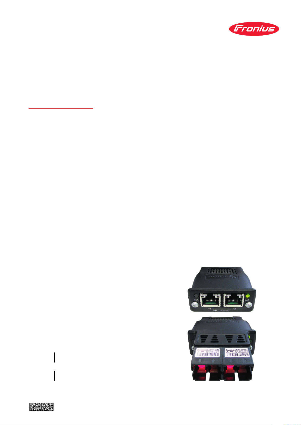
RI FB Inside/i
RI MOD/i CC-M40 ProfiNet
DE
EN-US
Bedienungsanleitung
Operating instructions
42,0410,1917 038-07122022
Page 2

Page 3

Inhaltsverzeichnis
Allgemeines 4
Sicherheit 4
Anschlüsse und Anzeigen am RJ 45 Modul 4
Anzeigen am Fiber Optic (FO) Modul 5
Eigenschaften der Datenübertragung 6
Konfigurationsparameter 7
Roboter-Interface konfigurieren 8
Funktion DIP Schalter 8
Konfiguration der Prozessdaten-Breite 8
Knotenadresse einstellen mit DIP-Schalter(Beispiel) 8
IP-Einstellungen 10
Die Webseite der Stromquelle 10
SmartManager der Stromquelle aufrufen und anmelden 10
Ein- und Ausgangssignale 11
Datentypen 11
Verfügbarkeit der Eingangssignale 11
Eingangssignale (vom Roboter zur Stromquelle) 12
Wertebereich Working mode 17
Wertebereich Processline selection 17
Wertebereich TWIN mode 18
Wertebereich Documentation mode 18
Wertebereich Process controlled correction 18
Verfügbarkeit der Ausgangssignale 19
Ausgangssignale (von der Stromquelle zum Roboter) 19
Zuordnung Sensorstatus 1-4 22
Wertebereich Safety status 22
Wertebereich Process Bit 23
Ein- und Ausgangssignale Retrofit Image 24
Eingangssignale 24
Wertebereich Betriebsarten 25
Ausgangssignale 25
DE
3
Page 4

Allgemeines
(12)(11)(10)
(14)(13)
(9)
(1)
(2)
(3)
(4)
(5)
(6)
(7)
(8)
Sicherheit
Anschlüsse und
Anzeigen am RJ
45 Modul
WARNUNG!
Fehlbedienung und fehlerhaft durchgeführte Arbeiten können schwerwiegende
Personen- und Sachschäden verursachen.
Alle in diesem Dokument beschriebenen Arbeiten und Funktionen dürfen nur
von geschultem Fachpersonal ausgeführt werden, wenn folgende Dokumente
vollständig gelesen und verstanden wurden:
dieses Dokument
▶
die Bedienungsanleitung des Roboterinterface “RI FB Inside/i“
▶
sämtliche Dokumente der Systemkomponenten, insbesondere Sicherheits-
▶
vorschriften
(1) TX+
(2) TX-
(3) RX+
(6) RX-
(4) Normalerweise nicht verwen-
(5)
(7)
(8)
det; um die Signalvollständigkeit sicherzustellen, sind diese Pins miteinander verbunden und enden über einen Filterkreis am Schutzleiter (PE).
(9) LED Verbindung/Aktivität
Anschluss 2
(10) LED MS (Modulstatus)
(11) RJ 45 Ethernet Anschluss 2
(12) RJ 45 Ethernet Anschluss 1
(13) LED Verbindung/Aktivität Anschluss 1
(14) LED NS (Netzwerkstatus)
LED Netzwerkstatus
Status Bedeutung
Aus Offline; keine Spannungsversorgung oder keine Verbin-
dung mit IO Controller
Leuchtet grün Online (RUN); Verbindung mit IO Controller herge-
stellt,
IO Controller in Betrieb
Blinkt grün (einmal) Online (STOP); Verbindung mit IO Controller herge-
stellt, IO Controller nicht in Betrieb, IO-Daten fehlerhaft, IRT-Synchronisation nicht fertiggestellt
Blinkt grün (dauerhaft)
4
Von Engineering-Tools verwendet, um den NetzwerkKnoten zu identifizieren
Page 5
LED Netzwerkstatus
(1)
(4)(3)(4)(3)
(5) (2) (6)
Status Bedeutung
Leuchtet rot das Modul hat einen schweren internen Fehler festge-
stellt
Blinkt rot (einmal) Stationsname nicht gesetzt
Blinkt rot (zweimal) IP-Adresse nicht gesetzt
Blinkt rot (dreimal) Konfigurationsfehler; erwartete Identifikation stimmt
nicht mit der tatsächlichen Identifikation überein
LED Modulstatus
Status Bedeutung
Aus keine Versorgungsspannung oder
Modul im Setup- oder Initialisierungs-Modus
Leuchtet grün normaler Betrieb
Blinkt grün (einmal) Diagnoseprozess läuft
Leuchtet rot Ausnahmezustand, schwerer Fehler, etc.
Leuchtet abwechselnd rot und grün
Firmwareupdate. Während des Updates das Modul
nicht von der Spannungsversorgung trennen - dies
könnte Schäden am Modul zur Folge haben!
DE
Anzeigen am Fiber Optic (FO)
Modul
LED Verbindung/Aktivität
Status Bedeutung
Aus Keine Verbindung, keine Aktivität
Leuchtet grün Verbindung hergestellt, keine Aktivität
Flackert grün Verbindung hergestellt, Aktivität vorhanden
(1) LED Netzwerkstatus
(2) LED Modulstatus
(3) Optisches Signal vom Anybus
CompactCom Modul
(4) Optisches Signal vom Anybus
CompactCom Modul
(5) LED Verbindung/Aktivität, An-
schluss 1
(6) LED Verbindung/Aktivität, An-
schluss 2
LED Netzwerkstatus
Status Bedeutung
Aus Offline; keine Spannungsversorgung oder keine Verbin-
dung mit IO Controller
5
Page 6

LED Netzwerkstatus
Status Bedeutung
Leuchtet grün Online (RUN); Verbindung mit IO Controller herge-
stellt,
IO Controller in Betrieb
Blinkt grün (einmal) Online (STOP); Verbindung mit IO Controller herge-
stellt, IO Controller nicht in Betrieb, IO-Daten fehlerhaft, IRT-Synchronisation nicht fertiggestellt
Blinkt grün (dauerhaft)
Leuchtet rot das Modul hat einen schweren internen Fehler festge-
Blinkt rot (einmal) Stationsname nicht gesetzt
Blinkt rot (zweimal) IP-Adresse nicht gesetzt
Blinkt rot (dreimal) Konfigurationsfehler; erwartete Identifikation stimmt
LED Modulstatus
Status Bedeutung
Aus keine Versorgungsspannung oder
Leuchtet grün normaler Betrieb
Blinkt grün (einmal) Diagnoseprozess läuft
Leuchtet rot Ausnahmezustand, schwerer Fehler, etc.
Leuchtet abwechselnd rot und grün
Von Engineering-Tools verwendet, um den NetzwerkKnoten zu identifizieren
stellt
nicht mit der tatsächlichen Identifikation überein
Modul im Setup- oder Initialisierungs-Modus
Firmwareupdate. Während des Updates das Modul
nicht von der Spannungsversorgung trennen - dies
könnte Schäden am Modul zur Folge haben!
Eigenschaften
der Datenübertragung
LED Verbindung/Aktivität (5+6)
Status Bedeutung
Aus Keine Verbindung, keine Aktivität
Leuchtet grün Verbindung hergestellt, keine Aktivität
Flackert grün Verbindung hergestellt, Aktivität vorhanden
Übertragungstechnik:
Ethernet
Medium:
Bei der Auswahl der Kabel, Stecker und Abschluss-Widerstände ist die Profinet Montagerichtline für die Planung und Installation von Profinet Systemen
zu beachten.
Seitens Hersteller wurden die EMV-Tests mit dem Kabel IEC-C5DD4UGG0150A20A20-E durchgeführt.
Seitens Hersteller wurden die EMV-Tests mit einer Buszykluszeit von 32ms
durchgeführt.
Übertragungs-Geschwindigkeit:
100 Mbit/s, Full-Duplex-Mode
6
Page 7

Busanschluss:
Ethernet RJ45 / SCRJ (Fiber Optic)
DE
Konfigurationsparameter
Bei einigen Roboter-Steuerungen kann es erforderlich sein die hier beschriebe-
nen Konfigurationsparameter anzugeben, damit das Busmodul mit dem Roboter kommunizieren kann.
Parameter Wert
Device ID 0301
Vendor ID 01B0
hex
hex
(769
(432
) Fronius ProfiNet IO 2-Port
dez
) Fronius International GmbH
dez
Station Type fronius-fb-inside-pn-2p
Die folgenden Parameter geben Detailinformationen über das Busmodul. Auf
die Daten kann durch den Profibus-Master mittels azyklischer Lese/SchreibDienste zugegriffen werden.
Parameter Wert
IM Manufacturer ID 01B0
hex
(432
) Fronius International GmbH
dez
IM Order ID 4.044.014
IM Revision Counter 0001
IM Profile ID F600
IM Profile Specific
0004
(1
hex
(62976
hex
(4
hex
)
dez
dez
) No profile
dez
) Generic Device
Type
IM Version 0101
IM Supported 0000
hex
hex
(257
(0
)
dez
) IM0 supported
dez
7
Page 8
Roboter-Interface konfigurieren
(1)
(2)(3)
ON
OFF
Funktion
DIP Schalter
Konfiguration
der Prozessdaten-Breite
Der DIP‑Schalter (1) am Roboter-Interface RI FB Inside/i dient zur Einstellung
der Prozessdaten-Breite
-
der Knotenadresse / IP-Adresse
-
Werksseitig sind alle Positionen des
DIP‑Schalters in der Stellung OFF (3).
Das entspricht dem binären Wert 0.
Die Stellung ON (2) entspricht dem
binären Wert 1.
DIP-Schalter
8 7 6 5 4 3 2 1 Konfiguration
OFF OFF - - - - - -
Standard Image
320 Bit
Knotenadresse
einstellen mit
DIP-Schalter
(Beispiel)
OFF ON - - - - - -
ON OFF - - - - - -
Umfang abhängig von Busmodul
Economy Image
128 Bit
Retro Fit
ON ON - - - - - - Nicht verwendet
Über die Prozessdaten-Breite wird der Umfang der übertragenen Datenmenge
definiert.
Welche Datenmenge übertragen werden kann ist abhängig von
der Roboter-Steuerung
-
der Anzahl der Stromquellen
-
der Art der Stromquellen
-
„Intelligent Revolution“
-
„Digital Revolution“ (Retro Fit)
-
DIP-Schalter
8 7 6 5 4 3 2 1 Knotenadresse
- - OFF OFF OFF OFF OFF ON 1
- - OFF OFF OFF OFF ON OFF 2
- - OFF OFF OFF OFF ON ON 3
- - ON ON ON ON ON OFF 62
- - ON ON ON ON ON ON 63
8
Page 9

Die Knotenadresse wird mit den Positionen 1 bis 6 des DIP-Schalters eingestellt.
Die Einstellung erfolgt im Binärformat. Das ergibt einen Einstellbereich von 1 bis
63 im Dezimalformat
HINWEIS!
Nach jeder Änderung der DIP-Schalter Einstellungen ist ein Neustart des Interface durchzuführen damit die Änderungen wirksam werden.
(Neustart = Unterbrechen und Wiederherstellen der Spannungsversorgung
oder Ausführen der entsprechenden Funktion auf der Webseite der Stromquelle)
DE
9
Page 10
IP-Einstellungen Bei Auslieferung ist über die DIP-Schalter die Knotenadresse 0 eingestellt. Das
3
2
1
4
xx.x.xxx.x
1.9.0-16501.9508
entspricht folgenden IP-Einstellungen:
IP-Adresse: 0.0.0.0
-
Subnet-Mask: 0.0.0.0
-
Default-Gateway: 0.0.0.0
-
Bei ProfiNet wird die Vergabe der IP-Adresse, der Subnet-Mask und des DefaultGateways vom Master durchgeführt. Auch ein Gerätename wird dem Interface
vom Master zugewiesen.
Die Webseite der
Stromquelle
SmartManager
der Stromquelle
aufrufen und anmelden
Die Stromquelle verfügt über eine eigene Webseite, den SmartManager.
Sobald die Stromquelle in einem Netzwerk integriert ist, kann der SmartManager
über die IP-Adresse der Stromquelle aufgerufen werden.
Abhängig von Anlagenkonfiguration und Software-Erweiterungen enthält der
SmartManager folgende Einträge:
Übersicht
-
Update
-
Screenshot
-
Sichern & Wiederherstellen
-
Funktionspakete
-
Job-Daten
-
Kennlinienübersicht
-
RI FB INSIDE/i
-
Voreinstellungen / System / Information ==> IP-Adresse der Stromquelle no-
1
tieren
IP-Adresse im Suchfeld des Browsers eingeben
2
Benutzername und Kennwort eingeben
3
Werkseinstellung:
Benutzername = admin
Kennwort = admin
Angezeigten Hinweis bestätigen
4
Der SmartManager der Stromquelle wird angezeigt.
10
Page 11

Ein- und Ausgangssignale
Datentypen Folgende Datentypen werden verwendet:
UINT16 (Unsigned Integer)
-
Ganzzahl im Bereich von 0 bis 65535
SINT16 (Signed Integer)
-
Ganzzahl im Bereich von -32768 bis 32767
Umrechnungsbeispiele:
für positiven Wert (SINT16)
-
z.B. gewünschter Drahtvorschub x Faktor
12.3 m/min x 100 = 1230
für negativen Wert (SINT16)
-
z.B. gewünschte Lichtbogen-Korrektur x Faktor
-6.4 x 10 = -64
= FFC0
dez
= 04CE
dez
hex
DE
hex
Verfügbarkeit
der Eingangssignale
Die nachfolgend angeführten Eingangssignale sind ab Firmware V2.3.0 bei allen
Inside/i-Systemen verfügbar.
11
Page 12

Eingangssignale
(vom Roboter
zur Stromquelle)
Adresse
relativ absolut
Prozess-
Image
WORD
0
BIT
BIT
BYTE
0 0 Welding Start steigend
1 1 Robot ready High
2 2 Working mode Bit 0 High
3 3 Working mode Bit 1 High
0
4 4 Working mode Bit 2 High
5 5 Working mode Bit 3 High
6 6 Working mode Bit 4 High
7 7 —
0 8 Gas on steigend
1 9 Wire forward steigend
2 10 Wire backward steigend
3 11 Error quit steigend
4 12 Touch sensing High
1
5 13 Torch blow out steigend
6 14 Processline selection Bit 0 High Siehe Tabelle
7 15 Processline selection Bit 1 High
Signal
Aktivität /
Datentyp
Bereich
Wertebereich
Working mode
Wertebereich
Siehe Tabelle
auf Seite 17
Processline
selection auf
Seite 17
Faktor
Standard
ü ü
Economy
12
Page 13

Adresse
relativ absolut
Prozess-
Image
DE
WORD
1
BIT
BIT
BYTE
0 16 Welding Simulation High
1 17 Synchro pulse on High
2 18 —
3 19 —
2
4 20 —
5 21 —
6 22 Wire brake on High
7 23 Torchbody Xchange High
0 24 —
1 25 Teach mode High
2 26 —
3 27 —
3
4 28 —
5 29 Wire sense start steigend
6 30 Wire sense break steigend
7 31 —
Signal
Aktivität /
Datentyp
Bereich
Faktor
Standard
ü ü
Economy
13
Page 14

Adresse
relativ absolut
Prozess-
Image
WORD
2
BIT
BIT
BYTE
0 32 TWIN mode Bit 0 High Siehe Tabelle
1 33 TWIN mode Bit 1 High
2 34 —
3 35 —
4 36 —
4
5 37 Documentation mode High
6 38 —
7 39 —
0 40 —
1 41 —
2 42 —
3 43 —
5
4 44 —
Signal
Aktivität /
Datentyp
Bereich
Wertebereich
TWIN mode auf
Wertebereich
Documentation
mode auf Seite
Seite 18
Siehe Tabelle
18
Faktor
Standard
ü ü
Economy
5 45 —
6 46 —
7 47
Disable process controlled
correction
High
14
Page 15

Adresse
relativ absolut
Prozess-
Image
DE
WORD
3
BIT
BIT
BYTE
0 48 —
1 49 —
2 50 —
3 51 —
6
4 52 —
5 53 —
6 54 —
7 55 —
0 56 ExtInput1 => OPT_Output 1 High
1 57 ExtInput2 => OPT_Output 2 High
2 58 ExtInput3 => OPT_Output 3 High
3 59 ExtInput4 => OPT_Output 4 High
7
4 60 ExtInput5 => OPT_Output 5 High
5 61 ExtInput6 => OPT_Output 6 High
6 62 ExtInput7 => OPT_Output 7 High
7 63 ExtInput8 => OPT_Output 8 High
Signal
Aktivität /
Datentyp
Bereich
Faktor
Standard
ü ü
Economy
8 0-7 64-71
4
9 0-7 72-79
10,
5
0-7 80-95
11
Welding characteristic- / Job
number
Beim Schweißverfahren
MIG/MAG Puls-Synergic,
MIG/MAG Standard-Synergic,
MIG/MAG Standard-Manuell,
MIG/MAG PMC,
MIG/MAG LSC,
CMT, ConstantWire:
Wire feed speed command value
Beim Job-Betrieb:
Power correction
UINT16 0 bis 1000 1
-327,68
SINT16
SINT16
bis 327,67
[m/min]
-20,00 bis
20,00
[%]
100
100
ü ü
ü ü
15
Page 16

Adresse
relativ absolut
Prozess-
Image
WORD
6
7
BYTE
12,
0-7 96-111
13
14,
0-7 112-127
15
BIT
BIT
Signal
Beim Schweißverfahren
MIG/MAG Puls-Synergic,
MIG/MAG Standard-Synergic,
MIG/MAG PMC,
MIG/MAG LSC,
CMT:
Arclength correction
Beim Schweißverfahren
MIG/MAG Standard-Manuell:
Welding voltage
Beim Job-Betrieb:
Arclength correction
Beim Schweißverfahren ConstantWire:
Hotwire current
Beim Schweißverfahren
MIG/MAG Puls-Synergic,
MIG/MAG Standard-Synergic,
MIG/MAG PMC,
MIG/MAG LSC,
CMT:
Pulse-/dynamic correction
Aktivität /
Datentyp
SINT16
UINT16
SINT16
UINT16
SINT16
Bereich
-10,0 bis
10,0
[Schritte]
0,0 bis
6553,5
[V]
-10,0 bis
10,0
[Schritte]
0,0 bis
6553,5
[A]
-10,0 bis
10,0
[Schritte]
10
10
10
10
10
Faktor
Standard
ü ü
ü ü
Economy
16 0-7 128-135
8
17 0-7 136-143
18 0-7 144-151
9
19 0-7 152-159
20 0-7 160-167
10
21 0-7 168-175
22 0-7 176-183
11
23 0-7 184-191
Beim Schweißverfahren
MIG/MAG Standard-Manuell:
Dynamic
Wire retract correction UINT16
Welding speed UINT16
Process controlled correction
—
UINT16
0,0 bis
10,0
[Schritte]
0,0 bis
10,0
[Schritte]
0,0 bis
1000,0
[cm/min]
Siehe Tabelle
Wertebereich
Process control-
led correction
auf Seite 18
10
10
10
ü
ü
ü
ü
16
Page 17

Adresse
relativ absolut
Prozess-
Image
DE
WORD
BYTE
BIT
24 0-7 192-199
12
25 0-7 200-207
26 0-7 208-215
13
27 0-7 216-223
28 0-7 224-231
14
29 0-7 232-239
30 0-7 240-247
15
31 0-7 248-255
32 0-7 256-263
16
33 0-7 264-271
34 0-7 272-279
17
35 0-7 280-287
36 0-7 288-295
18
37 0-7 296-303
38 0-7 304-311
19
39 0-7 312-319
BIT
Signal
Aktivität /
Datentyp
Bereich
—
—
—
Wire forward / backward
length
UINT16
OFF / 1
bis 65535
[mm]
OFF / 0,5
Wire sense edge detection UINT16
bis 20,0
10
[mm]
—
—
Seam number UINT16
0 bis
65535
Faktor
Standard
Economy
ü
ü
ü
1
ü
ü
ü
ü
1
ü
Wertebereich
Working mode
Wertebereich
Processline
selection
Bit 4 Bit 3 Bit 2 Bit 1 Bit 0 Beschreibung
0 0 0 0 0 Parameteranwahl intern
0 0 0 0 1 Kennlinien Betrieb Sonder 2-Takt
0 0 0 1 0 Job-Betrieb
0 1 0 0 0 Kennlinien Betrieb 2-Takt
0 1 0 0 1 MIG/MAG Standard-Manuell 2-Takt
1 0 0 0 1 Kühlmittel-Pumpe stoppen
Wertebereich Betriebsart
Bit 1 Bit 0 Beschreibung
0 0 Prozesslinie 1 (default)
0 1 Prozesslinie 2
1 0 Prozesslinie 3
1 1 Reserviert
Wertebereich Prozesslinien-Auswahl
17
Page 18

Wertebereich
TWIN mode
Bit 1 Bit 0 Beschreibung
0 0 TWIN Single mode
0 1 TWIN Lead mode
1 0 TWIN Trail mode
1 1 Reserve
Wertebereich TWIN-Betriebsart
Wertebereich
Documentation
mode
Wertebereich
Process controlled correction
Bit 0 Beschreibung
0 Nahtnummer von Stromquelle (intern)
1 Nahtnummer von Roboter (Word 19)
Wertebereich Dokumentationsmodus
Prozess
Signal
Aktivität /
PMC Arc length stabilizer SINT16
Wertebereich prozessabhängige Korrektur
Wertebereich
Datentyp
Einstellbereich
-327,8 bis +327,7
0,0 bis +5,0 Volt 10
Einheit
Faktor
18
Page 19

Verfügbarkeit
der Ausgangssignale
Ausgangssignale
(von der Stromquelle zum Roboter)
Adresse
relativ absolut
Die nachfolgend angeführten Ausgangssignale sind ab Firmware V2.3.0 bei allen
Inside/i-Systemen verfügbar.
Prozess-
Image
DE
WORD
0
BYTE
BIT
0 0 Heartbeat Powersource High/Low 1 Hz
1 1 Power source ready High
2 2 Warning High
3 3 Process active High
0
4 4 Current flow High
5 5 Arc stable- / touch signal High
6 6 Main current signal High
7 7 Touch signal High
0 8 Collisionbox active Low
1 9 Robot Motion Release High
2 10 Wire stick workpiece High
3 11 —
1
4 12 Short circuit contact tip High
5 13
BIT
Signal
Parameter selection internally
Aktivität /
Datentyp
High
Bereich
0 = Kollisi-
on oder
Kabel-
bruch
Standard
Faktor
ü ü
Economy
6 14
7 15 Torch body gripped High
Characteristic number
valid
High
19
Page 20

Adresse
relativ absolut
Prozess-
Image
WORD
1
BYTE
BIT
0 16
1 17 Correction out of range High
2 18 —
3 19 Limitsignal High
2
4 20 —
5 21 —
6 22 Main supply status Low
7 23 —
0 24 Sensor status 1 High
1 25 Sensor status 2 High
2 26 Sensor status 3 High
3 27 Sensor status 4 High
3
4 28 —
5 29 —
6 30 —
BIT
Signal
Command value out of
range
Aktivität /
Datentyp
High
Bereich
Siehe Tabelle Zu-
ordnung Sensorsta-
tus 1-4 auf Seite
22
Faktor
Standard
ü ü
Economy
7 31 —
0 32 —
1 33 —
2 34 —
3 35 Safety status Bit 0 High Siehe Tabelle Wer-
4
4 36 Safety status Bit 1 High
5 37 —
6 38 Notification High
2
7 39 System not ready High
0 40 —
1 41 —
2 42 —
3 43 —
5
4 44 —
5 45 —
6 46 —
tebereich Safety
status auf Seite 22
ü ü
20
7 47 —
Page 21

Adresse
relativ absolut
Prozess-
Image
DE
WORD
3
BYTE
BIT
0 48 Process Bit 0 High
1 49 Process Bit 1 High
2 50 Process Bit 2 High
3 51 Process Bit 3 High
6
4 52 Process Bit 4 High
5 53 —
6 54 Touch signal gas nozzle High
7 55
0 56
1 57
2 58
3 59
7
4 60
BIT
Signal
TWIN synchronization
active
ExtOutput1 <= OPT_Input1
ExtOutput2 <= OPT_Input2
ExtOutput3 <= OPT_Input3
ExtOutput4 <= OPT_Input4
ExtOutput5 <= OPT_Input5
Aktivität /
Datentyp
High
High
High
High
High
High
Bereich
Siehe Tabelle Wer-
tebereich Process
Bit auf Seite 23
Faktor
Standard
ü ü
Economy
5 61
6 62
7 63
8 0-7 64-71
4
9 0-7 72-79
10 0-7 80-87
5
11 0-7 88-95
12 0-7 96-103
6
13 0-7 104-111
14 0-7 112-119
7
15 0-7 120-127
16 0-7 128-135
8
17 0-7 136-143
18 0-7 144-151
9
19 0-7 152-159
ExtOutput6 <= OPT_Input6
ExtOutput7 <= OPT_Input7
ExtOutput8 <= OPT_Input8
Welding voltage UINT16
Welding current UINT16
Wire feed speed SINT16
Actual real value for
seam tracking
Error number UINT16
Warning number UINT16
High
High
High
UINT16
0,0 bis
655,35 [V]
0,0 bis
6553,5 [A]
-327,68
bis 327,67
[m/min]
0 bis
6,5535
0 bis
65535
0 bis
65535
100
10
100
10000
1
1
ü ü
ü ü
ü ü
ü ü
ü
ü
21
Page 22

Adresse
relativ absolut
Prozess-
Image
WORD
BYTE
BIT
20 0-7 160-167
10
21 0-7 168-175
22 0-7 176-183
11
23 0-7 184-191
24 0-7 192-199
12
25 0-7 200-207
26 0-7 208-215
13
27 0-7 216-223
28 0-7 224-231
14
29 0-7 232-239
30 0-7 240-247
15
31 0-7 248-255
32 0-7 256-263
16
33 0-7 264-271
BIT
Signal
Motor current M1 SINT16
Motor current M2 SINT16
Motor current M3 SINT16
—
—
—
Wire position SINT16
Aktivität /
Datentyp
Bereich
-327,68
bis 327,67
[A]
-327,68
bis 327,67
[A]
-327,68
bis 327,67
[A]
-327,68
bis 327,67
[mm]
100
100
100
100
Faktor
Standard
Economy
ü
ü
ü
ü
ü
ü
ü
34 0-7 272-279
17
35 0-7 280-287
36 0-7 288-295
18
37 0-7 296-303
38 0-7 304-311
19
39 0-7 312-319
Zuordnung Sensorstatus 1-4
Wertebereich
Safety status
—
—
—
Signal Beschreibung
Sensor status 1 OPT/i WF R Drahtende (4,100,869)
Sensor status 2 OPT/i WF R Drahtfass (4,100,879)
Sensor status 3 OPT/i WF R Ringsensor (4,100,878)
Sensor status 4 Drahtpufferset CMT TPS/i (4,001,763)
Bit 1 Bit 0 Beschreibung
0 0 Reserve
ü
ü
ü
22
0 1 Halt
1 0 Stopp
Page 23

Bit 1 Bit 0 Beschreibung
Wertebereich
Process Bit
1 1 Nicht eingebaut / aktiv
Bit 4 Bit 3 Bit 2 Bit 1 Bit 0 Beschreibung
0 0 0 0 0 kein Prozess oder Parameteranwahl
intern
0 0 0 0 1 MIG/MAG Puls-Synerigc
0 0 0 1 0 MIG/MAG Standard-Synergic
0 0 0 1 1 MIG/MAG PMC
0 0 1 0 0 MIG/MAG LSC
0 0 1 0 1 MIG/MAG Standard-Manuell
0 0 1 1 0 Elektrode
0 0 1 1 1 WIG
0 1 0 0 0 CMT
0 1 0 0 1 ConstantWire
DE
23
Page 24

Ein- und Ausgangssignale Retrofit Image
Eingangssignale Die nachfolgend angeführten Ssignale sind ab Firmware V1.6.0 bei allen Inside/i-
Systemen verfügbar.
Akti-
Lfd.Nr Signalbezeichnung Bereich
E01 Schweißen ein High
E02 Roboter bereit High
vität
E03 Betriebsarten Bit 0 Siehe Tabelle
E04 Betriebsarten Bit 1 High
E05 Betriebsarten Bit 2 High
E06 —
E07 —
E08 —
E09 Gas Test High
E10 Drahtvorlauf High
E11 Drahtrücklauf High
E12 Error quit High
E13 Positionssuchen High
E14 Brenner ausblasen High
E15 —
E16 —
E17 - E24 Job-Nummer 0 bis 99
E25 - E31 Programmnummer 1 bis 127
E32 Schweißsimulation High
Wertebereich
Betriebsarten
auf Seite 25
High
nur in Betriebsart Job-Betrieb (E17 - E32):
E17 - E31 Job-Nummer 0 bis 999
E32 Schweißsimulation High
E33 - E40 Leistungs-Sollwert - Low Byte
E41 - E48 Leistungs-Sollwert - High Byte
Lichtbogen-Längenkorrektur, Soll-
E49 - E56
E57 - E64
E65 - E72 Puls- oder Dynamikkorrektur
E73 - E80 —
wert
Low Byte
Lichtbogen-Längenkorrektur, Sollwert
High Byte
0 bis 65535
(0 bis 100 %)
0 bis 65535
(-30 bis +30 %)
0 bis 255
(-5 bis +5 %)
24
Page 25

Akti-
Lfd.Nr Signalbezeichnung Bereich
E81 - E88 —
E89 - E96 —
vität
DE
E97 E104
E105 -
E112
E113 Synchro Puls on High
E114 —
E115 —
E116 —
E117 Leistungs-Vollbereich (0 bis 30 m) High
E118 —
E119 —
E120 —
E121 -
E128
E129 -
E296
Schweißgeschwindigkeit - Low Byte
Schweißgeschwindigkeit - High Byte
—
—
0 bis 65535
(0 bis 6553,5 cm/
min)
Wertebereich
Betriebsarten
Ausgangssignale Die nachfolgend angeführten Ssignale sind ab Firmware V1.6.0 bei allen Inside/i-
Bit 2 Bit 1 Bit 0 Beschreibung
0 0 0 MIG/MAG Synergic Schweißen
0 0 1 MIG/MAG Synergic Schweißen
0 1 0 Job-Betrieb
0 1 1 Parameteranwahl intern
Systemen verfügbar.
Lfd.Nr Signalbezeichnung Bereich
A01 Lichtbogen stabil High
A02 Limitsignal High
A03 Prozess aktiv High
A04 Hauptstrom-Signal High
A05 Brenner-Kollisionsschutz High
Akti-
vität
A06 Stromquelle bereit High
A07 Kommunikation bereit High
A08 Life Cycle Toggle Bit (250ms) High
25
Page 26

Akti-
Lfd.Nr Signalbezeichnung Bereich
A09 - A16 —
A17 - A24 —
A25 —
A26 —
A27 —
A28 Draht vorhanden
A29 Überschreitung Kurzschlusszeit High
A30 —
A31 —
A32 Leistung außerhalb Bereich High
vität
A33 - A40
A41 - A48
A49 - A56 Schweißstrom-Istwert - Low Byte
A57 - A64 Schweißstrom-Istwert - High Byte
A65 - A72 Motorstrom
A73 - A80 —
A81 - A88 —
A89 - A96 —
A97 A104
A105 -
A112
A113 -
A120
A121 -
A128
Schweißspannungs-Istwert - Low
Byte
Schweißspannungs-Istwert - High
Byte
Drahtgeschwindigkeit - Low Byte
Drahtgeschwindigkeit - High Byte
—
—
0 bis 65535
(0 bis 100 V)
0 bis 65535
(0 bis 1000 A)
0 bis 255
(0 bis 5 A)
0 bis vDmax
26
A129 -
A296
—
Page 27

Table of contents
General 28
Safety 28
Connections and indicators on RJ 45 module 28
Indicators on Fiber Optic (FO) module 29
Data Transfer Properties 30
Configuration Parameters 31
Configuration of robot interface 32
Dip switch function 32
Configuration of the process data width 32
Set node address with dip switch(example) 32
IP Settings 34
The Website of the Power Source 34
Opening and Logging into the SmartManager for the Power Source 34
Input and output signals 35
Data types 35
Availability of Input Signals 35
Input signals (from robot to power source) 36
Value Range for Working Mode 41
Value range Process line selection 42
Value Range for TWIN Mode 42
Value Range for Documentation Mode 42
Value range for Process controlled correction 42
Availability of Output Signals 43
Output Signals (from Power Source to Robot) 43
Assignment of Sensor Statuses 1–4 46
Value range Safety status 46
Value Range for Process Bit 47
Retrofit Image Input and Output Signals 48
Input Signals 48
Value range for operating modes 49
Output Signals 49
EN-US
27
Page 28

General
(12)(11)(10)
(14)(13)
(9)
(1)
(2)
(3)
(4)
(5)
(6)
(7)
(8)
Safety
Connections and
indicators on RJ
45 module
WARNING!
Incorrect operation and faulty work can cause serious personal injury and material damage.
All work and functions described in this document must be performed only by
trained specialist personnel who have read and understood the following documents in full:
this document
▶
the Operating Instructions of the robot interface “RI FB Inside/i”
▶
all documents relating to system components, especially the safety rules
▶
(1) TX+
(2) TX-
(3) RX+
(6) RX-
(4) Not normally used; to ensure
(5)
(7)
(8)
signal completeness, these
pins must be interconnected
and, after passing through a
filter circuit, must terminate
at the ground conductor (PE).
(9) Connection/activity LED,
connection 2
(10) MS LED (module status)
(11) RJ-45 Ethernet connection 2
(12) RJ-45 Ethernet connection 1
(13) Connection/activity LED, connection 1
(14) NS LED (network status)
Network Status LED
Status Meaning
Off Offline; no power supply or no connection with IO Con-
troller
Lights up green Online (RUN); connection with IO Controller establis-
Flashes green (once) Online (STOP); connection with IO Controller establis-
hed,
IO Controller in operation
hed, IO Controller not in operation, IO data defective,
IRT synchronization not ready
28
Flashes green (permanently)
In use by engineering tools in order to identify network
nodes
Page 29

Network Status LED
(1)
(4)(3)(4)(3)
(5) (2) (6)
Status Meaning
Lights up red The module has identified a serious internal fault
Flashes red (once) Station name not set
Flashes red (twice) IP address not set
Flashes red (three
times)
Configuration error; expected identification does not
match the actual identification
Module Status LED
Status Meaning
Off No supply voltage or
module in the setup or initialization mode
Lights up green Normal operation
Flashes green (once) Diagnosis process running
Lights up red Emergency situation, serious fault, etc.
Lights up green and
red alternately
Firmware update. Do not disconnect the module from
the power supply during the update—this could result
in damage to the module.
Connection/Activity LED
Status Meaning
Off No connection, no activity
Lights up green Connection established, no activity
Flickers green Connection established, activity present
EN-US
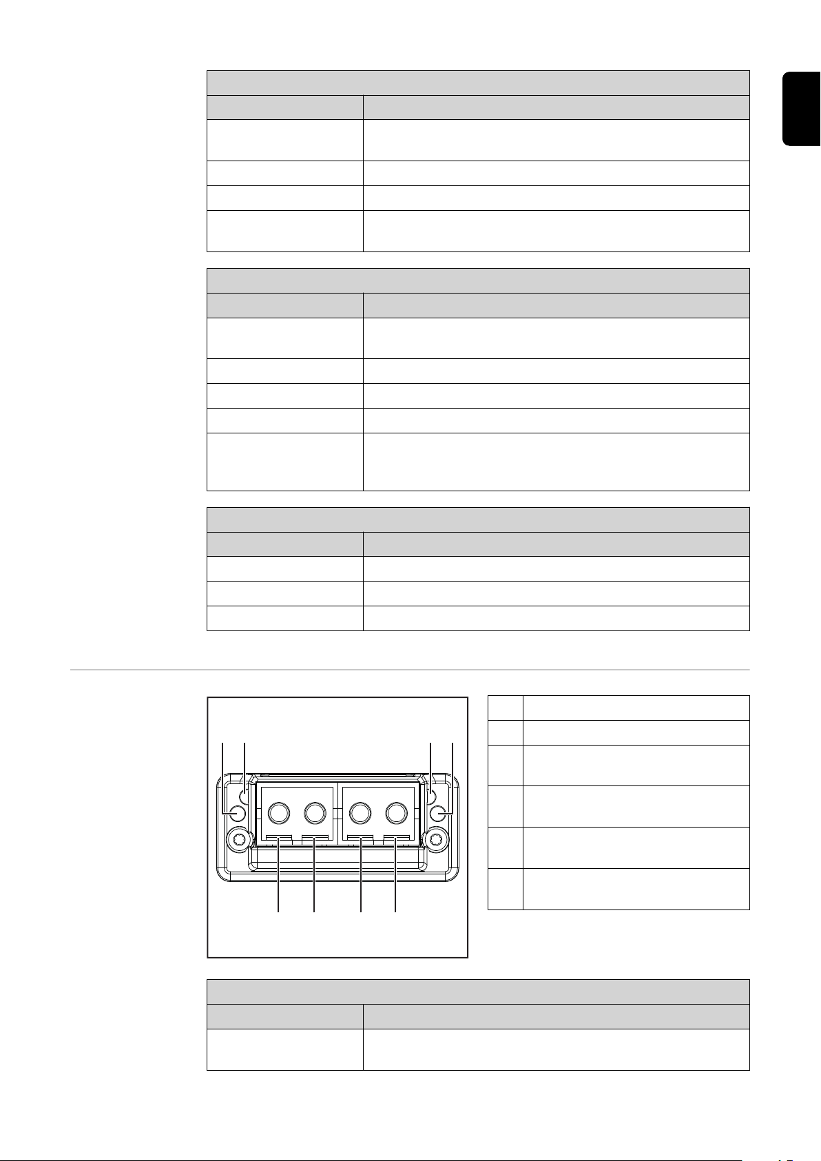
Indicators on Fiber Optic (FO)
module
Network Status LED
Status Meaning
Off Offline; no power supply or no connection with IO Con-
(1) Network Status LED
(2) Module Status LED
(3) Optical signal from Anybus
CompactCom module
(4) Optical signal from Anybus
CompactCom module
(5) Connection/activity LED, con-
nection 1
(6) Connection/activity LED, con-
nection 2
troller
29
Page 30

Network Status LED
Status Meaning
Lights up green Online (RUN); connection with IO Controller establis-
hed,
IO Controller in operation
Flashes green (once) Online (STOP); connection with IO Controller establis-
hed, IO Controller not in operation, IO data defective,
IRT synchronization not ready
Flashes green (permanently)
Lights up red The module has identified a serious internal fault
Flashes red (once) Station name not set
Flashes red (twice) IP address not set
Flashes red (three
times)
Module Status LED
Status Meaning
Off No supply voltage or
Lights up green Normal operation
Flashes green (once) Diagnosis process running
Lights up red Emergency situation, serious fault, etc.
Lights up green and
red alternately
In use by engineering tools in order to identify network
nodes
Configuration error; expected identification does not
match the actual identification
module in the setup or initialization mode
Firmware update. Do not disconnect the module from
the power supply during the update—this could result
in damage to the module.
Data Transfer
Properties
Connection/activity LED (5+6)
Status Meaning
Off No connection, no activity
Lights up green Connection established, no activity
Flickers green Connection established, activity present
Transfer technology:
Ethernet
Medium
When selecting the cable, plug, and terminating resistors, the Profinet assembly guideline for the planning and installation of Profinet systems must be observed.
The EMC tests were carried out by the manufacturer with the cable IEC-C5DD4UGG0150A20A20-E.
The EMC tests were carried out by the manufacturer with a bus cycle time of
32 ms.
Transmission speed:
100 Mbit/s, full duplex mode
30
Page 31

Bus connection:
Ethernet RJ45/SCRJ (fiber optic)
Configuration
Parameters
In some robot control systems, it may be necessary to state the configuration
parameters described here so that the bus module can communicate with the
robot.
Parameter Value
Device ID 0301
Vendor ID 01B0
hex
hex
(769
(432
) Fronius ProfiNet IO 2-Port
dec
) Fronius International GmbH
dec
Station type fronius-fb-inside-pn-2p
The following parameters provide detailed information about the bus module.
The Profibus master can access the data using acyclic read/write services.
Parameter Value
IM Manufacturer ID 01B0
hex
(432
) Fronius International GmbH
dec
IM Order ID 4.044.014
IM Revision Counter 0001
IM Profile ID F600
IM Profile Specific
0004
(1
hex
(62,976
hex
(4
hex
)
dec
dec
) No profile
dec
) Generic Device
Type
IM Version 0101
hex
(257
dec
)
EN-US
IM Supported 0000
hex
(0
) IM0 supported
dec
31
Page 32

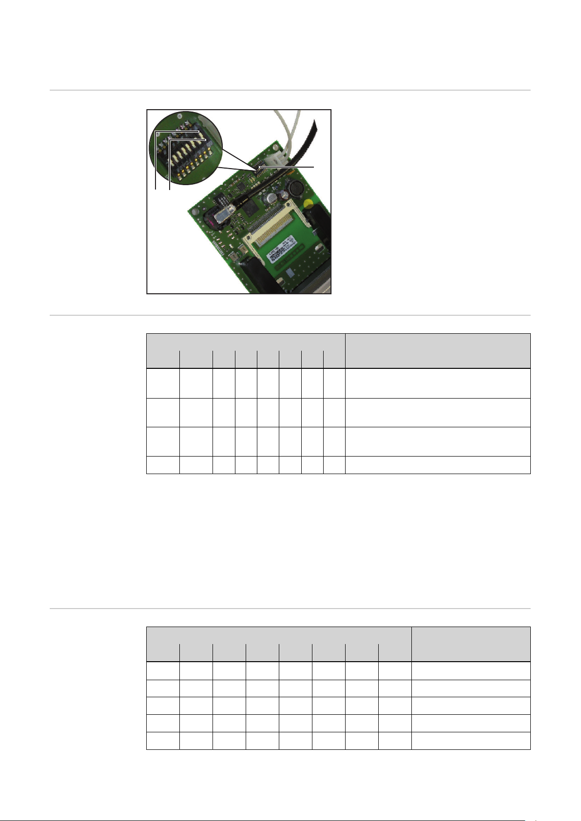
Configuration of robot interface
(1)
(2)(3)
ON
OFF
Dip switch function
Configuration of
the process data
width
The dip switch (1) on the robot interface RI FB Inside/i is used to configure
the process data width
-
the node address/IP address
-
At the factory all positions of the dip
switch are set to OFF (3).
This corresponds to the binary value 0.
The position (2) corresponds to the binary value 1.
Dip switch
8 7 6 5 4 3 2 1 Configuration
OFF OFF - - - - - -
Standard image
320 Bit
Set node address with dip
switch
(example)
OFF ON - - - - - -
ON OFF - - - - - -
Scope dependent on bus module
Economy image
128 Bit
Retro Fit
ON ON - - - - - - Not used
The process data width defines the scope of the transferred data volume.
The kind of data volume that can be transferred depends on
the robot controls
-
the number of power sources
-
the type of power sources
-
"Intelligent Revolution"
-
"Digital Revolution" (Retro Fit)
-
Dip switch
8 7 6 5 4 3 2 1 Node address
- - OFF OFF OFF OFF OFF ON 1
- - OFF OFF OFF OFF ON OFF 2
- - OFF OFF OFF OFF ON ON 3
- - ON ON ON ON ON OFF 62
- - ON ON ON ON ON ON 63
32
Page 33

The node address is set with positions 1 to 6 of the dip switch.
The configuration is carried out in binary format. This results in a configuration
range of 1 to 63 in decimal format
NOTE!
After every change of the configurations of the dip switch settings, the interface needs to be restarted so that the changes will take effect.
(Restart = interrupting and restoring the power supply
or executing the relevant function on the website of the power source)
EN-US
33
Page 34

IP Settings Node address 0 is set via the DIP switch on delivery. This corresponds to the fol-
3
2
1
4
xx.x.xxx.x
1.9.0-16501.9508
lowing IP settings:
IP address: 0.0.0.0
-
Subnet mask: 0.0.0.0
-
Default gateway: 0.0.0.0
-
In the case of ProfiNet, the assignment of the IP address, the subnet mask, and
the default gateway is carried out by the master. A device name is also assigned
to the interface by the master.
The Website of
the Power
Source
Opening and
Logging into the
SmartManager
for the Power
Source
The power source has its own website, the SmartManager.
As soon as the power source has been integrated into a network, the SmartManager can be opened via the IP address of the power source.
Depending on the system configuration and software upgrades, the SmartManager may contain the following entries:
Overview
-
Update
-
Screenshot
-
Save and restore
-
Function packages
-
Job data
-
Overview of characteristics
-
RI FB INSIDE/i
-
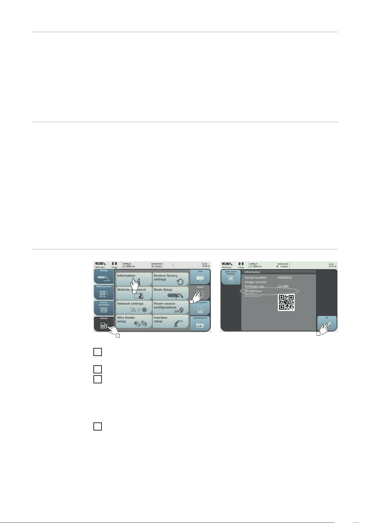
Presettings/System/Information ==> note down IP address of power source
1
Enter the IP address into the search field of the browser
2
Enter username and password
3
Factory setting:
Username = admin
Password = admin
Confirm displayed message
4
The SmartManager of the power source is displayed.
34
Page 35

Input and output signals
Data types The following data types are used:
UINT16 (Unsigned Integer)
-
Whole number in the range from 0 to 65535
SINT16 (Signed Integer)
-
Whole number in the range from -32768 to 32767
Conversion examples:
for a positive value (SINT16)
-
e.g. desired wire speed x factor
12.3 m/min x 100 = 1230
for a negative value (SINT16)
-
e.g. arc correction x factor
-6.4 x 10 = -64
= FFC0
dec
= 04CE
dec
hex
EN-US
hex
Availability of
Input Signals
The input signals listed below are available from firmware V2.3.0 for all Inside/i
systems.
35
Page 36

Input signals
(from robot to
power source)
Address
Relative
Process
image
Absolu-
te
WORD
0
BIT
BIT
BYTE
0 0 Welding Start
1 1 Robot ready High
2 2 Working mode Bit 0 High
3 3 Working mode Bit 1 High
0
4 4 Working mode Bit 2 High
5 5 Working mode Bit 3 High
6 6 Working mode Bit 4 High
7 7 —
0 8 Gas on
1 9 Wire forward
2 10 Wire backward
3 11 Error quit
1
Signal
Activity /
data type
Increa-
sing
Increa-
sing
Increa-
sing
Increa-
sing
Increa-
sing
See table Value
Working Mode
Range
Range for
on page 41
Factor
Standard
ü ü
Economy
4 12 Touch sensing High
5 13 Torch blow out
6 14 Processline selection Bit 0 High See table Value
7 15 Processline selection Bit 1 High
Increa-
sing
range Process li-
ne selection on
page 42
36
Page 37

Address
Relative
Process
image
Absolu-
te
WORD
1
BIT
BIT
BYTE
0 16 Welding Simulation High
1 17 Synchro pulse on High
2 18 —
3 19 —
2
4 20 —
5 21 —
6 22 Wire brake on High
7 23 Torchbody Xchange High
0 24 —
1 25 Teach mode High
2 26 —
3 27 —
4 28 —
3
5 29 Wire sense start
6 30 Wire sense break
Signal
Activity /
data type
Increa-
sing
Increa-
sing
Range
Factor
Standard
ü ü
Economy
EN-US
7 31 —
37
Page 38

Address
Relative
Process
image
Absolu-
te
WORD
2
BIT
BIT
BYTE
0 32 TWIN mode Bit 0 High See table Value
1 33 TWIN mode Bit 1 High
2 34 —
3 35 —
4
4 36 —
5 37 Documentation mode High
6 38 —
7 39 —
0 40 —
1 41 —
2 42 —
3 43 —
5
4 44 —
Signal
Activity /
data type
Range
Range for TWIN
Mode on page
See table Value
Range for Documentation Mode
on page 42
42
Factor
Standard
ü ü
Economy
5 45 —
6 46 —
7 47
Disable process controlled
correction
High
38
Page 39

Address
Relative
Process
image
Absolu-
te
WORD
3
BIT
BIT
BYTE
0 48 —
1 49 —
2 50 —
3 51 —
6
4 52 —
5 53 —
6 54 —
7 55 —
0 56 ExtInput1 => OPT_Output 1 High
1 57 ExtInput2 => OPT_Output 2 High
2 58 ExtInput3 => OPT_Output 3 High
3 59 ExtInput4 => OPT_Output 4 High
7
4 60 ExtInput5 => OPT_Output 5 High
5 61 ExtInput6 => OPT_Output 6 High
6 62 ExtInput7 => OPT_Output 7 High
7 63 ExtInput8 => OPT_Output 8 High
Signal
Activity /
data type
Range
Factor
Standard
ü ü
Economy
EN-US
8 0–7 64–71
4
9 0–7 72–79
10,
5
0–7 80–95
11
Welding characteristic- / Job
number
For the welding processes
MIG/MAG pulse synergic,
MIG/MAG standard synergic,
MIG/MAG standard manual,
MIG/MAG PMC,
MIG/MAG LSC,
CMT, ConstantWire:
Wire feed speed command value
For job mode:
Power correction
UINT16 0 to 1000 1
-327.68 to
SINT16
SINT16
327.67
[m/min]
-20.00 to
20.00
[%]
100
100
ü ü
ü ü
39
Page 40

Address
Relative
Process
image
Absolu-
te
WORD
6
7
BYTE
12,
0–7 96–111
13
14,
0–7 112–127
15
BIT
BIT
Signal
For the welding processes
MIG/MAG pulse synergic,
MIG/MAG standard synergic,
MIG/MAG PMC,
MIG/MAG LSC,
CMT:
Arclength correction
For the welding process
MIG/MAG standard manual:
Welding voltage
For job mode:
Arclength correction
For the welding process ConstantWire:
Hotwire current
For the welding processes
MIG/MAG pulse synergic,
MIG/MAG standard synergic,
MIG/MAG PMC,
MIG/MAG LSC,
CMT:
Pulse-/dynamic correction
Activity /
data type
SINT16
UINT16
SINT16
UINT16
SINT16
Range
-10.0 to
10.0
[steps]
0.0 to
6553.5
[V]
-10.0 to
10.0
[steps]
0.0 to
6553.5
[A]
-10.0 to
10.0
[steps]
10
10
10
10
10
Factor
Standard
ü ü
ü ü
Economy
8
9
10
16 0–7
17 0–7
18 0–7
19 0–7
20 0–7
21 0–7
128–
135
136–
143
144–
151
152–
159
160–
167
168–
175
For the welding process
MIG/MAG standard manual:
Dynamic
Wire retract correction UINT16
Welding speed UINT16
Process controlled correction
UINT16
0.0 to
10.0
[steps]
0.0 to
10.0
[steps]
0.0 to
1000.0
[cm/min]
See table Value
range for Pro-
cess controlled
correction on
page 42
10
10
10
ü
ü
ü
40
Page 41

Address
Relative
Process
image
Absolu-
te
WORD
11
12
13
14
15
BYTE
22 0–7
23 0–7
24 0–7
25 0–7
26 0–7
27 0–7
28 0–7
29 0–7
30 0–7
31 0–7
BIT
BIT
176–
183
184–
191
192–
199
200–
207
208–
215
216–
223
224–
231
232–
239
240–
247
248–
255
Signal
—
—
—
—
Wire forward / backward
length
Activity /
data type
UINT16
Range
OFF / 1 to
65535
[mm]
Factor
Standard
Economy
ü
ü
ü
ü
1
ü
EN-US
32 0–7
16
33 0–7
34 0–7 272–279
17
35 0–7
36 0–7
18
37 0–7
38 0–7
19
39 0–7
Value Range for
Working Mode
256–
263
264–
271
280–
287
288–
295
296–
303
304–
311
312–
319
Bit 4 Bit 3 Bit 2 Bit 1 Bit 0 Description
Wire sense edge detection UINT16
—
—
Seam number UINT16
0 0 0 0 0 Internal parameter selection
OFF / 0.5
to 20.0
[mm]
0 to
65,535
10
1
ü
ü
ü
ü
0 0 0 0 1 Special 2-step mode characteristics
41
Page 42

Bit 4 Bit 3 Bit 2 Bit 1 Bit 0 Description
0 0 0 1 0 Job mode
0 1 0 0 0 2-step mode characteristics
0 1 0 0 1 2-step MIG/MAG standard manual
1 0 0 0 1 Stop coolant pump
Value range for operating mode
Value range Process line selection
Value Range for
TWIN Mode
Bit 1 Bit 0 Description
0 0 Process line 1 (default)
0 1 Process line 2
1 0 Process line 3
1 1 Reserved
Value range for process line selection
Bit 1 Bit 0 Description
0 0 TWIN Single mode
0 1 TWIN Lead mode
1 0 TWIN Trail mode
1 1 Reserved
Value range for TWIN mode
Value Range for
Documentation
Mode
Value range for
Process controlled correction
Bit 0 Description
0 Seam number of power source (internal)
1 Seam number of robot (Word 19)
Value range for documentation mode
Process
Signal
Activity /
data type
PMC Arc length stabilizer SINT16
Value range for process-dependent correction
Value range
configuration
range
Unit
-327.8 to +327.7
0.0 to +5.0 Volts 10
Factor
42
Page 43

Availability of
Output Signals
Output Signals
(from Power
Source to Robot)
Address
relative absolute
The output signals listed below are available from firmware V2.3.0 for all Inside/i
systems.
EN-US
Process
image
WORD
0
BYTE
BIT
0 0 Heartbeat Powersource High/Low 1 Hz
1 1 Power source ready High
2 2 Warning High
3 3 Process active High
0
4 4 Current flow High
5 5 Arc stable- / touch signal High
6 6 Main current signal High
7 7 Touch signal High
0 8 Collisionbox active Low
1 9 Robot Motion Release High
2 10 Wire stick workpiece High
3 11 —
1
4 12 Short circuit contact tip High
5 13
BIT
Signal
Parameter selection internally
Activity /
data type
High
Range
0 = collisi-
on or ca-
ble break
Standard
Factor
ü ü
Economy
6 14
7 15 Torch body gripped High
Characteristic number
valid
High
43
Page 44

Address
relative absolute
Process
image
WORD
1
BYTE
BIT
0 16
1 17 Correction out of range High
2 18 —
3 19 Limitsignal High
2
4 20 —
5 21 —
6 22 Main supply status Low
7 23 —
0 24 Sensor status 1 High
1 25 Sensor status 2 High
2 26 Sensor status 3 High
3 27 Sensor status 4 High
3
4 28 —
5 29 —
6 30 —
BIT
Signal
Command value out of
range
Activity /
data type
High
Range
See table Assign-
ment of Sensor Sta-
tuses 1–4 on page
46
Factor
Standard
ü ü
Economy
7 31 —
0 32 —
1 33 —
2 34 —
3 35 Safety status Bit 0 High See table Value ran-
4
4 36 Safety status Bit 1 High
5 37 —
6 38 Notification High
2
7 39 System not ready High
0 40 —
1 41 —
2 42 —
3 43 —
5
4 44 —
5 45 —
6 46 —
ge Safety status on
page 46
ü ü
44
7 47 —
Page 45

Address
relative absolute
Process
image
WORD
3
BYTE
BIT
0 48 Process Bit 0 High
1 49 Process Bit 1 High
2 50 Process Bit 2 High
3 51 Process Bit 3 High
6
4 52 Process Bit 4 High
5 53 —
6 54 Touch signal gas nozzle High
7 55
0 56
1 57
2 58
3 59
7
4 60
BIT
Signal
TWIN synchronization
active
ExtOutput1 <= OPT_Input1
ExtOutput2 <= OPT_Input2
ExtOutput3 <= OPT_Input3
ExtOutput4 <= OPT_Input4
ExtOutput5 <= OPT_Input5
Activity /
data type
High
High
High
High
High
High
Range
See table Value
Range for Process
Bit on page 47
Factor
Standard
ü ü
Economy
EN-US
5 61
6 62
7 63
8 0-7 64-71
4
9 0-7 72-79
10 0-7 80-87
5
11 0-7 88-95
12 0-7 96-103
6
13 0-7 104-111
14 0-7 112-119
7
15 0-7 120-127
16 0-7 128-135
8
17 0-7 136-143
18 0-7 144-151
9
19 0-7 152-159
ExtOutput6 <= OPT_Input6
ExtOutput7 <= OPT_Input7
ExtOutput8 <= OPT_Input8
Welding voltage UINT16
Welding current UINT16
Wire feed speed SINT16
Actual real value for
seam tracking
Error number UINT16
Warning number UINT16
High
High
High
UINT16
0.0 to
655.35 [V]
0.0 to
6553.5 [A]
-327.68 to
327.67 [m/
min]
0 to
6.5535
0 to
65535
0 to
65535
100
10
100
10000
1
1
ü ü
ü ü
ü ü
ü ü
ü
ü
45
Page 46

Address
relative absolute
Process
image
WORD
BYTE
BIT
20 0-7 160-167
10
21 0-7 168-175
22 0-7 176-183
11
23 0-7 184-191
24 0-7 192-199
12
25 0-7 200-207
26 0-7 208-215
13
27 0-7 216-223
28 0-7 224-231
14
29 0-7 232-239
30 0-7 240-247
15
31 0-7 248-255
32 0-7 256-263
16
33 0-7 264-271
34 0-7 272-279
17
35 0-7 280-287
BIT
Signal
Motor current M1 SINT16
Motor current M2 SINT16
Motor current M3 SINT16
—
—
—
Wire position SINT16
—
Activity /
data type
Range
-327.68 to
327.67 [A]
-327.68 to
327.67 [A]
-327.68 to
327.67 [A]
-327.68 to
327.67
[mm]
100
100
100
100
Factor
Standard
Economy
ü
ü
ü
ü
ü
ü
ü
ü
36 0-7 288-295
18
37 0-7 296-303
38 0-7 304-311
19
39 0-7 312-319
Assignment of
Sensor Statuses
1–4
Value range
Safety status
—
—
Signal Description
Sensor status 1 OPT/i WF R wire end (4,100,869)
Sensor status 2 OPT/i WF R wire drum (4,100,879)
Sensor status 3 OPT/i WF R ring sensor (4,100,878)
Sensor status 4 Wire buffer set CMT TPS/i (4,001,763)
Bit 1 Bit 0 Description
0 0 Reserve
ü
ü
46
0 1 Hold
1 0 Stop
1 1 Not installed / active
Page 47

Value Range for
Process Bit
Bit 4 Bit 3 Bit 2 Bit 1 Bit 0 Description
0 0 0 0 0 No internal parameter selection or
process
0 0 0 0 1 MIG/MAG pulse synergic
0 0 0 1 0 MIG/MAG standard synergic
0 0 0 1 1 MIG/MAG PMC
0 0 1 0 0 MIG/MAG LSC
0 0 1 0 1 MIG/MAG standard manual
0 0 1 1 0 Electrode
0 0 1 1 1 TIG
0 1 0 0 0 CMT
0 1 0 0 1 ConstantWire
EN-US
47
Page 48

Retrofit Image Input and Output Signals
Input Signals The signals listed below are available from firmware V1.6.0 for all Inside/i sys-
tems.
Serial no. Signal designation Range Action
E01 Welding on High
E02 Robot ready High
E03 Operating mode bit 0 See table Value
E04 Operating mode bit 1 High
E05 Operating mode bit 2 High
E06 —
E07 —
E08 —
E09 Gas test High
E10 Wire forward High
E11 Wire backward High
E12 Error quit High
E13 Position search High
E14 Purge welding torch High
E15 —
E16 —
E17 - E24 Job number 0 to 99
E25 - E31 Program number 1 to 127
E32 Welding simulation High
range for opera-
ting modes on
page 49
High
Only in Job mode (E17 - E32):
E17 - E31 Job number 0 to 999
E32 Welding simulation High
E33 - E40 Output set value - Low byte
E41 - E48 Output set value - High byte
E49 - E56
E57–E64
E65 - E72 Pulse or dynamic correction
E73–E80 —
E81 - E88 —
E89 - E96 —
Arc length correction, set value
Low byte
Arc length correction, set value
High byte
0 to 65535
(0 to 100%)
0 to 65535
(-30 to +30%)
0 to 255
(-5 to +5%)
48
Page 49

Serial no. Signal designation Range Action
E97 E104
E105 -
E112
E113 SynchroPulse on High
E114 —
E115 —
E116 —
E117 Output full range (0 to 30 m) High
E118 —
E119 —
E120 —
E121 -
E128
E129 -
E296
Welding speed - Low byte
Welding speed - High byte
—
—
0 to 65535
(0 to 6553.5 cm/
min)
EN-US
Value range for
operating modes
Output Signals The signals listed below are available from firmware V1.6.0 for all Inside/i sys-
Bit 2 Bit 1 Bit 0 Description
0 0 0 MIG/MAG Synergic welding
0 0 1 MIG/MAG Synergic welding
0 1 0 Job mode
0 1 1 Internal parameter selection
tems.
Seq. no Signal designation Range Action
A01 Arc stable High
A02 Limit signal High
A03 Process active High
A04 Main current signal High
A05 Welding torch collision protection High
A06 Power source ready High
A07 Communication ready High
A08 Life Cycle Toggle Bit (250ms) High
A09 - A16 —
A17 - A24 —
A25 —
49
Page 50

Seq. no Signal designation Range Action
A26 —
A27 —
A28 Wire present
A29 Short circuit time exceeded High
A30 —
A31 —
A32 Power out of range High
A33 - A40
A41 - A48
A49 - A56
A57 - A64
A65 - A72 Motor current
A73 - A80 —
A81 - A88 —
A89 - A96 —
A97 A104
A105 -
A112
A113 -
A120
Welding voltage actual value - Low
byte
Welding voltage actual value - High
byte
Welding current actual value - Low
byte
Welding current actual value - High
byte
Wire speed - Low byte
Wire speed - High byte
—
0 to 65535
(0 to 100 V)
0 to 65535
(0 to 1000 A)
0 to 255
(0 to 5 A)
0 to vDmax
A121 -
A128
A129 -
A296
—
—
50
Page 51

EN-US
51
Page 52

 Loading...