

Page 1

Operating
Instructions
RI FB PRO/i TWIN Controller
RI MOD/i CC Ethernet/IP-2P TWIN FANUC
DE
EN-US
JA
Bedienungsanleitung
Operating instructions
操作手順
42,0410,2650 005-03022023
Page 2

Page 3

Inhaltsverzeichnis
Allgemeines 4
Sicherheit 4
Anschlüsse und Anzeigen 4
Eigenschaften der Datenübertragung 5
Konfigurationsparameter 6
Voraussetzungen für den Betrieb des Busmodules 6
IP-Adresse des Busmoduls einstellen 7
IP-Adresse des Busmoduls einstellen 7
Ein- und Ausgangssignale 9
Datentypen 9
Verfügbarkeit der Eingangssignale 9
Eingangssignale (vom Roboter zur Stromquelle) 9
Wertebereich Working mode 20
Wertebereich Processline selection 20
Wertebereich Operating mode TWIN System 20
Wertebereich Documentation mode 21
Wertebereich Process controlled correction 21
Wertebereich Command value selection 21
WertebereichPulse synchronization ratio 21
Verfügbarkeit der Ausgangssignale 22
Ausgangssignale (von der Stromquelle zum Roboter) 22
Zuordnung Sensorstatus 1-4 29
Wertebereich Safety status 29
TAG-Tabelle 29
DE
3
Page 4

Allgemeines
1234567
8
Sicherheit
WARNUNG!
Gefahr durch Fehlbedienung und fehlerhaft durchgeführte Arbeiten.
Schwere Personen- und Sachschäden können die Folge sein.
Alle in diesem Dokument beschriebenen Arbeiten und Funktionen dürfen
▶
nur von technisch geschultem Fachpersonal ausgeführt werden.
Dieses Dokument vollständig lesen und verstehen.
▶
Sämtliche Sicherheitsvorschriften und Benutzerdokumentationen dieses
▶
Gerätes und aller Systemkomponenten lesen und verstehen.
WARNUNG!
Gefahr durch elektrischen Strom.
Schwere Personen- und Sachschäden können die Folge sein.
Vor Beginn der Arbeiten alle beteiligten Geräte und Komponenten ausschal-
▶
ten und vom Stromnetz trennen.
Alle beteiligten Geräte und Komponenten gegen Wiedereinschalten sichern.
▶
WARNUNG!
Gefahr durch unplanmäßige Signalübertragung.
Schwere Personen- und Sachschäden können die Folge sein.
Über das Interface keine sicherheitsrelevanten Signale übertragen.
▶
Anschlüsse und
Anzeigen
1 TX+
2 TX-
3 RX+
6 RX-
4,5,7,8Normalerweise nicht ver-
wendet; um die Signalvollständigkeit sicherzustellen, sind diese Pins miteinander verbunden und enden
über einen Filterkreis am
Schutzleiter (PE).
Pin-Belegung RJ 45 ProfiNet Anschluss
4
Page 5

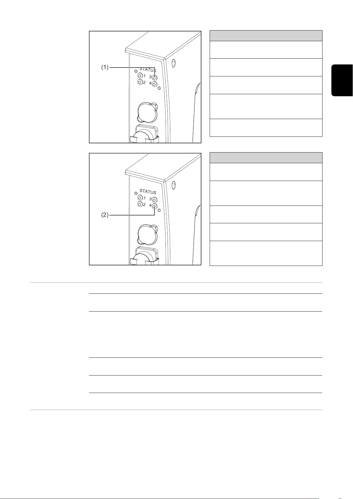
(1) LED MS - Modulstatus
Aus:
keine Versorgungsspannung
Leuchtet grün:
gesteuert durch einen Master
Blinkt grün (einmal):
Master nicht konfiguriert oder im
Ruhezustand
Leuchtet rot:
Hauptfehler (Ausnahmezustand,
schwerer Fehler, ...)
Blinkt rot:
behebbarer Fehler
(2) LED NS - Netzwerkstatus
Aus:
keine Versorgungsspannung oder
keine IP-Adresse
Leuchtet grün:
Online; eine oder mehrere Verbindungen hergestellt (CIP Kategorie 1
oder 3)
DE
Eigenschaften
der Datenübertragung
Blinkt grün:
Online; keine Verbindung hergestellt
Leuchtet rot:
doppelte IP-Adresse, schwerer Fehler
Blinkt rot:
Zeitüberlauf bei einer oder mehreren Verbindungen (CIP Kategorie 1
oder 3)
Übertragungstechnik
Ethernet
Medium
Bei der Auswahl der Kabel und Stecker ist die ODVA Empfehlung für die Planung und Installation vonEtherNet/IP Systemen zu beachten.
Seitens Hersteller wurden die EMV-Tests mit dem Kabel IE-C5ES8VG0030M40M40-F durchgeführt.
Übertragungs-Geschwindigkeit
10 Mbit/s or 100 Mbit/s
Busanschluss
RJ-45 Ethernet / M12
5
Page 6

Konfigurationsparameter
Bei einigen Robotersteuerungen kann es erforderlich sein die hier beschriebenen
Konfigurationsparameter anzugeben, damit das Busmodul mit dem Roboter
kommunizieren kann.
Parameter Wert Beschreibung
Voraussetzungen für den Betrieb des Busmodules
Vendor ID 0534
Device Type 000C
Product Code 0390
hex
hex
hex
(1332
(12
dez
(912
) Fronius International GmbH
dez
) Communication adapter
) Fronius FB Pro TwinEthernet/IP-2-
dez
Port
Product Name Fronius-FB-Pro-Twin-EtherNetIP(TM)
Size
Image Type
Standard
Image
Con-
Instance
Type
Produ-
cing In-
stance
suming
Instance
Instance
Name
Input Da-
ta Stan-
dard
Output
Data
Standard
Instance
Description
Data from power
source to robot
Data from robot
to power source
Instance
Number
105 120
155 120
[Byt
e]
Folgende Voraussetzungen müssen erfüllt sein, damit das Busmodul verwendet
werden kann:
Die Option CFG/i RI FB PRO TWIN Fanuc 1.0 muss in beiden Stromquellen
1.
eingebaut sein
Die Option CFG/i RI FB PRO TWIN Fanuc 1.0 muss im SmartManager beider
2.
Stromquellen aktiviert sein:
SnartManager der Stromquelle
6
Page 7

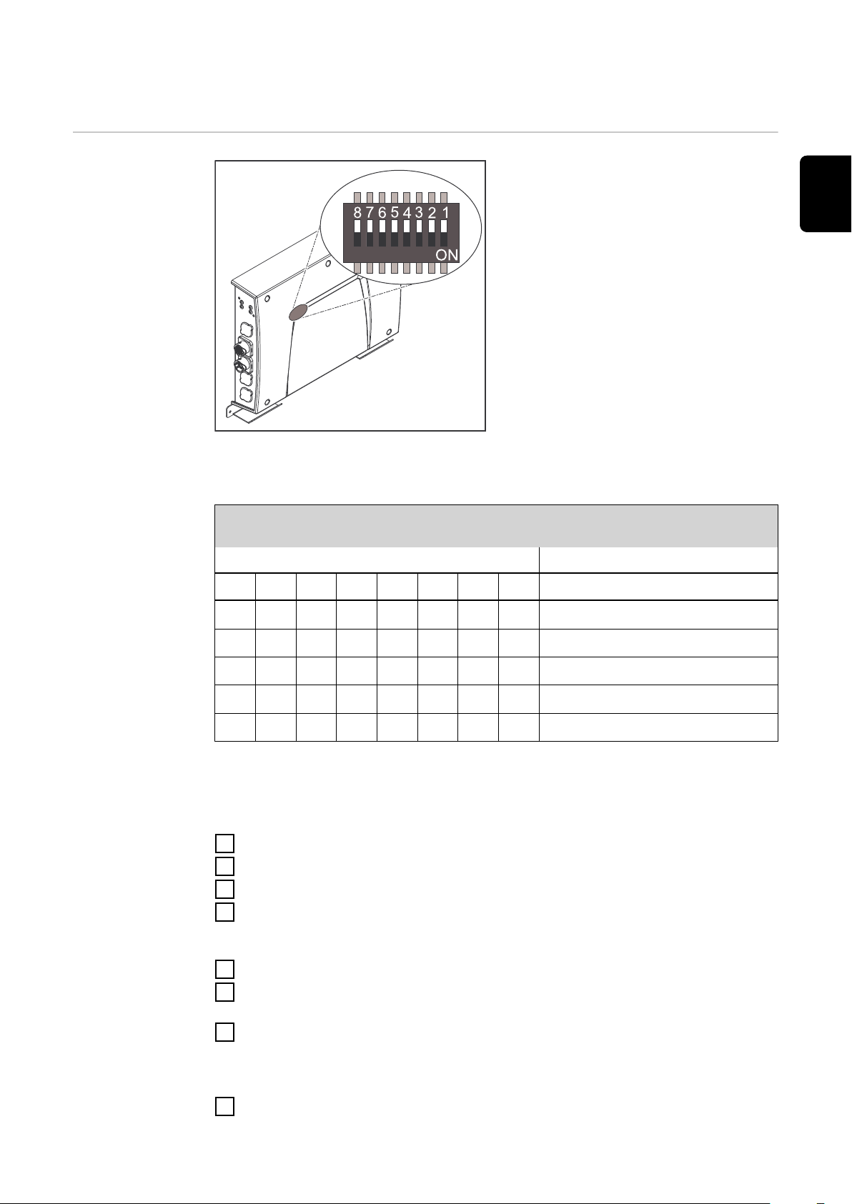
IP-Adresse des Busmoduls einstellen
DE
IP-Adresse des
Busmoduls einstellen
Die IP-Adresse des Busmoduls kann
eingestellt werden:
mit dem DIP-Schalter im Interface
1.
im Bereich 192.168.0.xx
(xx = DIP-Schalterstellung = 1 bis
63)
Werksseitig sind alle Positio-
-
nen in Stellung OFF geschaltet. In diesem Fall muss die
Einstellung der IP-Adresse auf
der Website der Stromquelle
eingestellt werden
auf der Website der Stromquelle
2.
(wenn alle Positionen des DIPSchalters in Stellung OFF geschaltet sind)
Die IP-Adresse wird mit den Positionen 1 bis 6 des DIP-Schalters eingestellt. Die
Einstellung erfolgt im Binärformat. Das ergibt einen Einstellbereich von 1 bis 63
im Dezimalformat.
Beispiel für das Einstellen der IP-Adresse des Busmoduls mit dem DIPSchalter im Interface:
DIP-Schalter
8 7 6 5 4 3 2 1 IP-Adresse
- -
- -
- -
- -
- -
OFF OFF OFF OFF OFF ON
OFF OFF OFF OFF ON OFF
OFF OFF OFF OFF ON ON
ON ON ON ON ON OFF
ON ON ON ON ON ON
1
2
3
62
63
Anleitung für das Einstellen der IP-Adresse auf der Website der Stromquelle
(SmartManager):
IP-Adresse der verwendeten Stromquelle notieren:
Am Bedienpanel der Stromquelle „Voreinstellungen“ auswählen
1
Am Bedienpanel der Stromquelle „System“ auswählen
2
Am Bedienpanel der Stromquelle „Information“ auswählen
3
Angezeigte IP-Adresse notieren (Beispiel: 10.5.72.13)
4
Website der Stromquelle im Internetbrowser aufrufen:
Computer mit dem Netzwerk der Stromquelle verbinden
5
IP-Adresse der Stromquelle in die Suchleiste des Internetbrowsers eingeben
6
und bestätigen
Standard-Benutzernamen (admin) und Passwort (admin) eingeben
7
Website der Stromquelle wird angezeigt
-
IP-Adresse des Busmoduls einstellen:
Auf der Website der Stromquelle den Reiter „RI FB PRO/i TWIN“ auswählen
8
7
Page 8

Bei Punkt „Feldbus Konfiguration“ die gewünschte IP-Adresse für das Inter-
9
face eingeben
Beispielsweise: 192.168.0.12
„Konfiguration setzen“ auswählen
10
„Feldbus-Modul neu starten“ auswählen
11
die eingestellte IP-Adresse wird übernommen
-
8
Page 9

Ein- und Ausgangssignale
Datentypen Folgende Datentypen werden verwendet:
UINT16 (Unsigned Integer)
-
Ganzzahl im Bereich von 0 bis 65535
SINT16 (Signed Integer)
-
Ganzzahl im Bereich von -32768 bis 32767
Umrechnungsbeispiele:
für positiven Wert (SINT16)
-
z.B. gewünschter Drahtvorschub x Faktor
12.3 m/min x 100 = 1230
für negativen Wert (SINT16)
-
z.B. gewünschte Lichtbogen-Korrektur x Faktor
-6.4 x 10 = -64
= FFC0
dez
= 04CE
dez
hex
DE
hex
Verfügbarkeit
der Eingangssignale
Eingangssignale
(vom Roboter
zur Stromquelle)
Die nachfolgend angeführten Eingangssignale sind ab Firmware V1.8.0 des RI
MOD/i CC Ethernet/IP-2P TWIN FANUC verfügbar.
9
Page 10

Adresse
relativ absolut
WORD
1
BYTE
1
2
BIT
1 1 Welding Start steigend
2 2 Robot ready High
3 3 Working mode Bit 0
4 4 Working mode Bit 1
5 5 Working mode Bit 2
6 6 Working mode Bit 3
7 7 Working mode Bit 4
8 8 —
1 9 Gas on steigend
2 10 Wire forward steigend
3 11 Wire backward steigend
4 12 Error quit steigend
5 13 Touch sensing High
6 14 Torch blow out steigend
BIT
Signal
Aktivität
/
Datentyp Bereich
Siehe nachfolgende
UINT5
(0 - 31)
Tabelle Wertebe-
reich Working mode
auf Seite 20
Faktor
7 15 Processline selection Bit 0 High Siehe nachfolgende
Tabelle Wertebe-
8 16 Processline selection Bit 1 High
1 17 Welding Simulation High
2 18 —
3 19 —
4 20 —
3
5 21 —
6 22 Booster manual High
7 23 Wire brake on High
8 24 Torchbody Xchange High
2
1 25 —
2 26 Teach mode High
3 27 —
4 28 —
4
5 29 —
reich Processline
selection auf Seite
20
10
6 30 Wire sense start High
7 31 Wire sense break High
8 32 —
Page 11

Adresse
relativ absolut
WORD
BYTE
5
3
BIT
1 33
2 34
3 35 —
4 36 —
5 37 —
6 38 Documentation mode High
7 39 —
8 40 —
1 41 —
BIT
Signal
Operating mode TWIN System
Bit 0
Operating mode TWIN System
Bit 1
Aktivität
/
Datentyp Bereich
High
High
Siehe nachfolgende
Tabelle Wertebe-
reich Operating mo-
de TWIN System auf
Seite 20
Siehe nachfolgende
Tabelle Wertebe-
reich Documentati-
on mode auf Seite
21
DE
Faktor
2 42 —
3 43 —
4 44 —
6
5 45 —
6 46 —
7 47 —
8 48
Disable Arclength stabilizer,
Power source 1 + 2
High
11
Page 12

Adresse
relativ absolut
WORD
4
BYTE
7
8
BIT
1 49 —
2 50 —
3 51 —
4 52 —
5 53 —
6 54 —
7 55 —
8 56 —
1 57 ExtInput1 => OPT_Output 1 High
2 58 ExtInput2 => OPT_Output 2 High
3 59 ExtInput3 => OPT_Output 3 High
4 60 ExtInput4 => OPT_Output 4 High
5 61 ExtInput5 => OPT_Output 5 High
6 62 ExtInput6 => OPT_Output 6 High
BIT
Signal
Aktivität
/
Datentyp Bereich
Faktor
7 63 ExtInput7 => OPT_Output 7 High
8 64 ExtInput8 => OPT_Output 8 High
1 65 —
2 66 —
3 67 —
9
5
10
4 68 —
5 69 —
6 70 —
7 71 —
8 72 —
1 73
2 74 —
3 75 —
4 76 —
5 77 —
6 78 —
Contact tip short circuit detection on
High
12
7 79 —
8 80 —
Page 13

Adresse
relativ absolut
WORD
BYTE
11
6
12
BIT
1 81 —
2 82 —
3 83 —
4 84 —
5 85 —
6 86 —
7 87 —
8 88 —
1 89 —
2 90 —
3 91 —
4 92 —
5 93 —
BIT
Signal
Aktivität
/
Datentyp Bereich
DE
Faktor
6 94 —
7 95 —
8 96 —
13
7
14
15
8
16
17,
9
18
1-16 97-112
1-16 113-128
1-16 129-144
Welding characteristic- / Job
number, Power source 1
Welding characteristic- / Job
number, Power source 2
Beim Schweißverfahren
MIG/MAG Puls-Synergic,
MIG/MAG Standard-Synergic,
MIG/MAG Standard-Manuell,
MIG/MAG PMC,
MIG/MAG LSC,
CMT, ConstantWire:
Wire feed speed command value, Power source 1
Beim Job-Betrieb:
Power correction, Power
source 1
UINT16 0 bis 65535 1
UINT16 0 bis 65535 1
-327,68 bis
SINT16
SINT16
327,67
[m/min]
-20,00 bis
20,00
[%]
100
100
13
Page 14

Adresse
relativ absolut
10
WORD
19,
20
BYTE
BIT
1-16 145-160
BIT
Signal
Beim Schweißverfahren
MIG/MAG Puls-Synergic,
MIG/MAG Standard-Synergic,
MIG/MAG Standard-Manuell,
MIG/MAG PMC,
MIG/MAG LSC,
CMT, ConstantWire:
Wire feed speed command value, Power source 2
Beim Job-Betrieb:
Power correction, Power
source 2
Beim Schweißverfahren
MIG/MAG Puls-Synergic,
MIG/MAG Standard-Synergic,
MIG/MAG PMC,
MIG/MAG LSC,
CMT:
Aktivität
/
Datentyp Bereich
-327,68 bis
SINT16
SINT16
SINT16
327,67
[m/min]
-20,00 bis
20,00
[%]
-10,0 bis 10,0
[Schritte]
Faktor
100
100
10
11
21,
22
1-16 161-176
Arclength correction, Power
source 1
Beim Schweißverfahren
MIG/MAG Standard-Manuell:
Welding voltage, Power source
1
Beim Job-Betrieb:
Arclength correction, Power
source 1
Beim Schweißverfahren ConstantWire:
Hotwire current, Power source
1
UINT16
SINT16
UINT16
0,0 bis 6553,5
[V]
-10,0 bis 10,0
[Schritte]
0,0 bis 6553,5
[A]
10
10
10
14
Page 15

Adresse
relativ absolut
WORD
12
BYTE
23,
24
BIT
1-16 177-192
BIT
Signal
Beim Schweißverfahren
MIG/MAG Puls-Synergic,
MIG/MAG Standard-Synergic,
MIG/MAG PMC,
MIG/MAG LSC,
CMT:
Arclength correction, Power
source 2
Beim Schweißverfahren
MIG/MAG Standard-Manuell:
Welding voltage, Power source
2
Beim Job-Betrieb:
Arclength correction, Power
source 2
Aktivität
/
Datentyp Bereich
SINT16
UINT16
SINT16
-10,0 bis 10,0
[Schritte]
0,0 bis 6553,5
[V]
-10,0 bis 10,0
[Schritte]
DE
Faktor
10
10
10
13
14
25,
26
27,
28
1-16 193-208
1-16 208-223
Beim Schweißverfahren ConstantWire:
Hotwire current, Power source
2
Beim Schweißverfahren
MIG/MAG Puls-Synergic,
MIG/MAG Standard-Synergic,
MIG/MAG PMC,
MIG/MAG LSC,
CMT:
Pulse-/dynamic correction,
Power source 1
Beim Schweißverfahren
MIG/MAG Standard-Manuell:
Dynamic, Power source 1
Beim Schweißverfahren
MIG/MAG Puls-Synergic,
MIG/MAG Standard-Synergic,
MIG/MAG PMC,
MIG/MAG LSC,
CMT:
Pulse-/dynamic correction,
Power source 2
UINT16
SINT16
UINT16
SINT16
0,0 bis 6553,5
[A]
-10,0 bis 10,0
[Schritte]
0,0 bis 10,0
[Schritte]
-10,0 bis 10,0
[Schritte]
10
10
10
10
Beim Schweißverfahren
MIG/MAG Standard-Manuell:
Dynamic, Power source 2
UINT16
0,0 bis 10,0
[Schritte]
10
15
Page 16

Adresse
relativ absolut
15
16
17
18
19
20
21
WORD
29
30
31
32
33
34
35
36
37
38
39
40
41
42
BYTE
BIT
1-16 225-240
1-16 241-256
1-16 257-272 Welding speed UINT16
1-16 273-288
1-16 289-304
1-16 305-320
1-16 321-336 Wire sense edge detection UINT16
BIT
Signal
Wire retract correction, Power
source 1
Wire retract correction, Power
source 2
Arclength stabilizer, Power
source 1
Arclength stabilizer, Power
source 2
Wire forward / wire backward
length
Aktivität
/
Datentyp Bereich
UINT16 0,0 bis 10,0 10
UINT16 0,0 bis 10,0 10
0,0 bis 6535,5
[cm/min]
UINT16 0,0 bis 5,0 10
UINT16 0,0 bis 5,0 10
OFF / 1 bis
UINT16
65355
[mm]
OFF / 0,5 bis
20,0
[mm]
Faktor
10
1
10
22
23
24
25
26
27
28
29
30
43
1-16 337-352 —
44
45
1-16 353-368 —
46
47
1-16 369-384 —
48
49
1-16 385-400 —
50
51
1-16 401-416 —
52
53
1-16 417-432 —
54
55
1-16 433-448 —
56
57
1-16 449-464 —
58
59
1-16 465-480 Seam number UINT16 0 bis 65535 1
60
16
Page 17

Adresse
relativ absolut
WORD
BYTE
61
31
BIT
1 481
2 482 —
3 483 —
4 484 —
5 485 Disable gas-settings High
6 486
7 487
8 488
1 489
2 490 —
BIT
Signal
Disable start-end-parameter
(Image)
Disable components setup
(TAG)
Disable language / units / standards (TAG)
Disable penetration stabilizer,
Power source 1 + 2
Enable arc break monitoring /
arc loss
Aktivität
/
Datentyp Bereich
High
High
High
High
High
DE
Faktor
62
3 491 —
4 492 —
5 493 —
6 494 —
7 495 —
8 496 —
17
Page 18

Adresse
relativ absolut
32
WORD
63
64
BYTE
BIT
1 497 —
2 498 —
3 499 —
4 500 —
5 501 —
6 502 —
7 503 —
8 504 —
1 505 —
2 506 —
3 507 —
4 508 —
5 509 —
6 510 —
BIT
Signal
Aktivität
/
Datentyp Bereich
Faktor
7 511
8 512 Command value selection Bit 1 High
65
33
66
67
34
68
69
35
70
71
36
72
73
37
74
75
38
76
39 77 1-8 609-616 TAG quantity UINT8 0 bis 5 1
1-16 513-528 TAG start address UINT16 1 bis 65535 1
1-16 529-544 TAG value 1
1-16 545-560 TAG value 2
1-16 561-576 TAG value 3
1-16 577-592 TAG value 4
1-16 593-608 TAG value 5
Command value selection Bit
0
High
Siehe nachfolgende
Tabelle Wertebe-
reich Command va-
lue selection auf Sei-
te 21
39 78 1 617 TAG command read steigend
39 78 2 618 TAG command write steigend
39 78 3-8 619-624 —
18
40
79
1-16 625-640 Gas preflow UINT16
80
0,0 bis 9,9
[s]
10
Page 19

Adresse
relativ absolut
WORD
BYTE
81
41
82
83
42
84
85
43
86
87
44
88
89
45
90
91
46
92
93
47
94
BIT
1-16 641-656 Gas postflow UINT16
1-16 657-672 Inching value UINT16
1-16 673-688 S2T - Starting current UINT16
1-16 689-704 S2T - Starting current time UINT16
1-16 705-720 S2T - Slope 1 UINT16
1-16 721-736 S2T - Slope 2 UINT16
1-16 737-752 S2T - End current UINT16
BIT
Signal
Aktivität
/
Datentyp Bereich
0,0 bis 9,9
[s]
-327,67 bis
327,67
[m/min]
0,0 bis 200
[%]
0,0 bis 9,9
[s]
0,0 bis 9,9
[s]
0,0 bis 9,9
[s]
0,0 bis 200
[%]
DE
Faktor
10
100
1
10
10
10
1
48
49
50
51
52
53
54
55
95
96
97
98
99
100
101
102
103
104
105
106
107
108
109
110
1-16 753-768 S2T - End current time UINT16
1-16 769-784 Start arclength correction SINT16 -10,0 bis 10,0 10
1-16 785-800 End arclength correction UINT16 -10,0 bis 10,0 10
1-16 801-816 Pulse synchronization ratio UINT16
1-16 817-832 Phase shift lead / trail UINT16
1-16 833-848 Ignition delay trail UINT16
1-16 849-864 —
1-16 865-880
Penetration stabilizer,
Power source 1
UINT16
0,0 bis 9,9
[s]
Siehe nachfolgende
Tabelle Wertebe-
reichPulse synchro-
nization ratio auf Sei-
te 21
0 bis 95
(255 = AUTO)
0,00 bis 2,00
(254 = OFF)
(255 = AUTO)
0,0 bis 10,0
[m/min]
10
1
100
10
56
57
111
112
113
114
1-16 881-896
1-16 897-912 —
Penetration stabilizer,
Power source 2
UINT16
0,0 bis 10,0
[m/min]
10
19
Page 20

Adresse
relativ absolut
WORD
BYTE
115
58
116
117
59
118
119
60
120
Wertebereich
Working mode
Aktivität
/
BIT
BIT
Signal
Datentyp Bereich
1-16 913-928 —
1-16 929-944 —
1-16 945-960 —
Bit 4 Bit 3 Bit 2 Bit 1 Bit 0 Beschreibung
0 0 0 0 0 Parameteranwahl intern
0 0 0 0 1 Kennlinien Betrieb Sonder 2-Takt
0 0 0 1 0 Job-Betrieb
0 1 0 0 0 Kennlinien Betrieb 2-Takt
0 1 0 0 1 MIG/MAG Standard-Manuell 2-Takt
Faktor
Wertebereich
Processline
selection
Wertebereich
Operating mode
TWIN System
1 0 0 0 1 Kühlmittel-Pumpe stoppen
Wertebereich Betriebsart
Bit 1 Bit 0 Beschreibung
0 0 Prozesslinie 1 (default)
0 1 Prozesslinie 2
1 0 Prozesslinie 3
1 1 Reserviert
Wertebereich Prozesslinien-Auswahl
Bit 1 Bit 0 Funktion Stromquelle 1 Funktion Stromquelle 2
0 0 Single mode OFF
0 1 TWIN Lead TWIN Trail
1 0 TWIN Trail TWIN Lead
20
1 1 OFF Single mode
Wertebereich Betriebsart TWIN System
Page 21

Wertebereich
Documentation
mode
Wertebereich
Process controlled correction
Bit 0 Beschreibung
0 Nahtnummer von Stromquelle (intern)
1 Nahtnummer von Roboter (Word 29)
Wertebereich Dokumentationsmodus
Prozess
Signal
Aktivität /
PMC Arc length stabilizer SINT16
Wertebereich prozessabhängige Korrektur
Wertebereich
Datentyp
Einstellbereich
-327,8 bis +327,7
0,0 bis +5,0 Volt 10
Einheit
DE
Faktor
Wertebereich
Command value
selection
Wertebereich
Pulse synchronization ratio
Bit 1 Bit 0 Beschreibung
0 0 Wire feed speed command value
0 1 Welding current command value
Wertebereich Signal Command value selection
Wert Beschreibung
1 Auto
2 1/1
3 1/2
4 1/3
Wertebereich Pulse synchronization ratio
21
Page 22

Verfügbarkeit
der Ausgangssignale
Ausgangssignale
(von der Stromquelle zum Roboter)
Adresse
relativ absolut
Die nachfolgend angeführten Ausgangssignale sind ab Firmware V1.8.0 des RI
MOD/i CC Ethernet/IP-2P TWIN FANUC verfügbar.
WORD
1
BYTE
1
2
BIT
1 1 Heartbeat Powersource High / Low 1 Hz
2 2 Power source ready High
3 3 Warning High
4 4 Process active High
5 5 Current flow High
6 6 Arc stable- / touch signal High
7 7 Main current signal High
8 8 Touch signal High
1 9 Collisionbox active Low
2 10
3 11 Wire stick workpiece High
4 12 —
BIT
Signal
Robot Motion Release, Power
source 1
Aktivität
/
Datentyp Bereich
0 = Kollision
oder Kabel-
bruch
High
Faktor
22
5 13 Short circuit contact tip High
6 14
7 15 —
8 16 Torch body gripped High
Parameter selection internally
High
Page 23

Adresse
relativ absolut
WORD
BYTE
3
2
4
BIT
1 17 Command value out of range High
2 18 Correction out of range High
3 19 —
4 20 Limitsignal, Power Source 1 High
5 21 —
6 22 Standby active High
7 23 Main supply status High
8 24 —
1 25
2 26
3 27
4 28
BIT
Signal
Sensor status 1, Power
Source 1
Sensor status 2, Power
Source 1
Sensor status 3, Power
Source 1
Sensor status 4, Power
Source 1
Aktivität
/
Datentyp Bereich
High
High
High
High
Siehe Tabelle Zuord-
nung Sensorstatus
1-4 auf Seite 29
DE
Faktor
5 29 —
6 30 —
7 31 —
8 32 —
1 33 —
2 34 —
3 35 —
4 36
5
5 37
6 38 —
7 39 Notification High
3
8 40 System not ready High
1 41 —
2 42 —
3 43 —
Safety status Bit 0, Power
Source 1
Safety status Bit 1, Power
Source 1
High
High
Siehe Tabelle Werte-
bereich Safety status
auf Seite 29
6
4 44 —
5 45 —
6 46 —
7 47 —
8 48 —
23
Page 24

Adresse
relativ absolut
WORD
4
BYTE
7
8
BIT
1 49 —
2 50 —
3 51 —
4 52 —
5 53 —
6 54 —
7 55 Gas nozzle touched High
8 56 —
1 57 ExtOutput1 <= OPT_Input1 High
2 58 ExtOutput2 <= OPT_Input2 High
3 59 ExtOutput3 <= OPT_Input3 High
4 60 ExtOutput4 <= OPT_Input4 High
5 61 ExtOutput5 <= OPT_Input5 High
6 62 ExtOutput6 <= OPT_Input6 High
BIT
Signal
Aktivität
/
Datentyp Bereich
Faktor
7 63 ExtOutput7 <= OPT_Input7 High
8 64 ExtOutput8 <= OPT_Input8 High
1 65 —
2 66
3 67 Limitsignal, Power source 2 High
9
5
10
4 68 —
5 69 —
6 70 —
7 71 —
8 72 —
1 73 —
2 74 —
3 75 —
4 76 —
5 77 —
6 78 —
Robot Motion Release, Power
source 2
High
24
7 79 —
8 80 —
Page 25

Adresse
relativ absolut
WORD
BYTE
11
6
BIT
1 81
2 82
3 83
4 84
5 85 —
6 86 —
7 87 —
8 88 —
1 89 —
2 90 —
3 91 —
BIT
Signal
Sensor status 1, Power
Source 2
Sensor status 2, Power
Source 2
Sensor status 3, Power
Source 2
Sensor status 4, Power
Source 2
Aktivität
/
Datentyp Bereich
High
High
High
High
Siehe Tabelle Zuord-
nung Sensorstatus
1-4 auf Seite 29
DE
Faktor
7
8
9
10
11
12
13
14
15
16
17
18
19
20
21
22
4 92
5 93
6 94 —
7 95 —
8 96 —
0-16 97-112
0-16 113-128
0-16 129-144
0-16 145-160
0-16 161-176
Safety status Bit 0, Power
Source 2
Safety status Bit 1, Power
Source 2
Real value welding voltage,
Power source 1
Real value welding voltage,
Power source 2
Real value welding current,
Power source 1
Real value welding current,
Power source 2
Real value wire feed speed,
Power source 1
High
High
UINT16
UINT16
UINT16
UINT16
SINT16
Siehe Tabelle Werte-
bereich Safety status
auf Seite 29
0,0 bis 655,35
[V]
0,0 bis 655,35
[V]
0,0 bis 6535,5
[A]
0,0 bis 6535,5
[A]
-327,68 bis
327,67
[m/min]
100
100
10
10
100
12
13
23
24
25
26
0-16 177-192
0-16 193-208
Real value wire feed speed,
Power source 2
Actual real value for seam
tracking
-327,68 bis
SINT16
UINT16 0 bis 6,5535
327,67
[m/min]
100
100
00
25
Page 26

Adresse
relativ absolut
14
15
16
17
18
19
20
WORD
27
28
29
30
31
32
33
34
35
36
37
38
39
40
BYTE
BIT
0-16 209-224 Error number, Power source 1 UINT16 0 bis 65535 1
0-16 225-240 Error number, Power source 2 UINT16 0 bis 65535 1
0-16 241-256
0-16 257-272
0-16 273-288
0-16 289-304
0-16 305-320
BIT
Signal
Motor current M1, Power
source 1
Motor current M1, Power
source 2
Motor current M2, Power
source 1
Motor current M2, Power
source 2
Motor current M3, Power
source 1
Aktivität
/
Datentyp Bereich
UINT16
UINT16
UINT16
UINT16
UINT16
0 bis 655,35
[A]
0 bis 655,35
[A]
0 bis 655,35
[A]
0 bis 655,35
[A]
0 bis 655,35
[A]
Faktor
100
100
100
100
100
21
22
23
24
25
26
27
28
29
41
42
43
44
45
46
47
48
49
50
51
52
53
54
58
56
57
58
0-16 321-336
0-16 337-352 Warning, Power source 1 UINT16 0 bis 65535 1
0-16 353-368 Warning, Power source 2 UINT16 0 bis 65535 1
0-16 369-384 Wire position, Power source 1 SINT16
0-16 385-400 Wire position, Power source 2 SINT16
0-16 401-416 —
0-16 417-432 —
0-16 433-448 —
0-16 449-464 —
Motor current M3, Power
source 2
UINT16
0 bis 655,35
[A]
-327,68 bis
327,67 [mm]
-327,68 bis
327,67 [mm]
100
100
100
26
30
59
0-16 465-480 —
60
Page 27

Adresse
relativ absolut
WORD
BYTE
61
31
62
BIT
1 481 —
2 482 —
3 483 —
4 484 —
5 485 —
6 486 —
7 487 —
8 488 —
1 489 —
2 490 —
3 491 —
4 492 —
5 493 —
BIT
Signal
Aktivität
/
Datentyp Bereich
DE
Faktor
32
6 494 —
7 495 —
8 496 —
1 497 —
2 498 —
3 499 —
4 500 —
63
5 501 —
6 502 —
7 503 —
8 504 —
1 505 —
2 506 —
3 507 —
4 508 —
64
5 509 —
6 510 —
33
34
7 511 —
8 512 —
65
1-16 513-528 TAG start address UINT16 1 bis 65535 1
66
67
1-16 529-544 TAG value 1
68
27
Page 28

Adresse
relativ absolut
WORD
BYTE
69
35
70
71
36
72
73
37
74
75
38
76
39 77 0-7 609-616 TAG quantity UINT8 1 bis 255
39 78 0 617 TAG command read steigend
39 78 1 618 TAG command write steigend
39 78 2-7 619-624 —
79
40
80
BIT
1-16 545-560 TAG value 2
1-16 561-576 TAG value 3
1-16 577-592 TAG value 4
1-16 593-608 TAG value 5
1-16 625-640 Cooler temperature UINT16
BIT
Signal
Aktivität
/
Datentyp Bereich
-100 bis 200
[°C]
Faktor
10
41
42
43
44
-
45
46
-
47
48
49
50
-
51
81
82
83
84
85
86
87
-
90
91
-
94
95
96
93
94
99
-
102
1-16 641-656 Cooler flow rate UINT16
1-16 657-672
1-16 673-688
1-32 689-720
1-32 721-752
1-16 753-768
1-16 769-784
1-32 785-816
Real energy value, Power
source 1
Power on value, Power source
1
Hour meter power on, Power
source 1
Hour meter arc on time,
Power source 1
Real energy value, Power
source 2
Power on value, Power source
2
Hour meter power on, Power
source 2
UINT16
UINT16
UINT32
UINT32
UINT16
UINT16
UINT32
-100 bis 100
[l/min]
0,0 bis 6535,5
[kJ]
0,0 bis 6535,5
[kW]
0 bis 100000
[h]
0 bis 100000
[h]
0,0 bis 6535,5
[kJ]
0,0 bis 6535,5
[kW]
0 bis 100000
[h]
10
10
10
10
10
10
10
10
28
52
53
54
103
-
-
1-32 817-848
106
107
108
1-16 849-864 —
Hour meter arc on time,
Power source 2
UINT32
0 bis 100000
[h]
10
Page 29

Adresse
relativ absolut
WORD
BYTE
109
55
110
111
56
112
113
57
114
115
58
116
117
59
118
119
60
120
BIT
1-16 865-880 —
1-16 881-896 —
1-16 897-912 —
1-16 913-928 —
1-16 929-944 —
1-16 945-960 —
BIT
Signal
Aktivität
/
Datentyp Bereich
DE
Faktor
Zuordnung Sensorstatus 1-4
Wertebereich
Safety status
TAG-Tabelle
Signal Beschreibung
Sensor status 1 OPT/i WF R Drahtende (4,100,869)
Sensor status 2 OPT/i WF R Drahtfass (4,100,879)
Sensor status 3 OPT/i WF R Ringsensor (4,100,878)
Sensor status 4 Drahtpufferset CMT TPS/i (4,001,763)
Bit 1 Bit 0 Beschreibung
0 0 Reserve
0 1 Halt
1 0 Stopp
1 1 Nicht eingebaut / aktiv
Adresse TAG
Aktivität /
Datentyp
Bereich Faktor
BIT 481 Disable Start-end-pa-
rameter:
TAG 1 —
TAG 2 —
TAG 3 —
High
29
Page 30

Aktivität /
Adresse TAG
TAG 4 —
TAG 5 —
Datentyp
Bereich Faktor
Aktivität /
Adresse TAG
BIT 482
TAG 6 —
TAG 7 —
TAG 8 —
TAG 9 —
Adresse TAG
BIT 483
TAG 10 —
TAG 11 —
TAG 12 —
TAG 13 —
TAG 14 —
TAG 15 —
TAG 16 —
Datentyp
Aktivität /
Datentyp
Bereich Faktor
Bereich Faktor
TAG 17 —
TAG 18 —
TAG 19 —
Aktivität /
Adresse TAG
BIT 484
TAG 20 —
TAG 21 —
TAG 22 —
TAG 23 —
TAG 24 —
TAG 25 —
TAG 26 —
TAG 27 —
TAG 28 —
TAG 29 —
Datentyp
Bereich Faktor
30
Page 31

Aktivität /
Adresse TAG
BIT 485
TAG 30 —
TAG 31 —
TAG 32 —
TAG 33 —
TAG 34 —
TAG 35 —
TAG 36 —
TAG 37 —
TAG 38 —
TAG 39 —
Datentyp
Bereich Faktor
DE
Aktivität /
Adresse TAG
BIT 486 Disable Components
setup:
TAG 40 Cooling unit mode,
Power source 1
TAG 41 Delay time flow sensor,
Power source 1
TAG 42 Touch sensing sensitivi-
ty,
Power source 1 + 2
TAG 43 Ignition timeout,
Power source 1 + 2
TAG 44 —
TAG 45 —
TAG 46 —
TAG 47 —
TAG 48 —
TAG 49 —
Datentyp
High
UINT16 1 bis 4 1
UINT16
UINT16 0 bis 10 1
UINT16 5 bis 100 1
Bereich Faktor
5 bis 25 (in 5er
Schritten)
1
Aktivität /
Adresse TAG
BIT 487 Disable Units / Stan-
dards / Language:
TAG 50 Language,
Power source 1 + 2
TAG 51 Unit (metric / imperial),
Power source 1 + 2
TAG 52 Welding standard
(AWS / EU),
Power source 1 + 2
TAG 53 —
Datentyp
High
UINT16 1 bis 35 1
UINT16 1 bis 2 1
UINT16 1 bis 2 1
Bereich Faktor
31
Page 32

Aktivität /
Adresse TAG
TAG 54 —
TAG 55 —
TAG 56 —
TAG 57 —
TAG 58 —
TAG 59 —
Datentyp
Bereich Faktor
TAG 60 Arc break filter time /
Arc loss error time
TAG 61 Arc break monitoring
reaction
TAG 62 —
TAG 63 —
TAG 64 —
TAG 65 —
TAG 66 —
TAG 67 —
TAG 68 —
TAG 69 —
Adresse TAG
BIT 488
TAG 150 —
TAG 151 —
UINT16 0,00 bis 2,00 [s] 100
UINT16 1 bis 2 1
Aktivität /
Datentyp
Bereich Faktor
TAG 152 —
TAG 153 —
TAG 154 —
TAG 155 —
TAG 156 —
TAG 157 —
TAG 158 —
TAG 159 —
Adresse TAG
TAG 10001 Welding voltage, Power
source 1
TAG 10002 Welding current, Power
source 1
TAG 10003 Wire feed speed, Power
source 1
Aktivität /
Datentyp
UINT16
UINT16
SINT16
Bereich Faktor
0,00 bis 655,35
[V]
0,00 bis 6553,5
[A]
-327,68 bis
327,67 [m/min]
100
10
100
32
Page 33

Adresse TAG
TAG 10004 Real value power, Power
source 1
Aktivität /
Datentyp
UINT16
Bereich Faktor
0,00 bis 6553,5
[kJ]
DE
10
TAG 10005 Ignitiondistance, Power
source 1 + 2
TAG 10006 —
TAG 10007 —
TAG 10008 —
TAG 10009 Welding voltage, Power
source 2
TAG 10010 Welding current, Power
source 2
TAG 10011 Wire feed speed, Power
source 2
TAG 10012 Real value power, Power
source 2
TAG 10013 —
TAG 10014 —
TAG 10015 —
Schweißrelevante Werte
Adresse TAG
UINT16 0 bis 100 [mm] 10
UINT16
UINT16
SINT16
UINT16
Aktivität /
Datentyp
0,00 bis 655,35
[V]
0,00 bis 6553,5
[A]
-327,68 bis
327,67 [m/min]
0,00 bis 6553,5
[kJ]
Bereich Faktor
100
10
100
10
TAG 10100 Vd max. processline,
Power source 1
TAG 10101 Max. current WeldSys-
tem, Power source 1
TAG 10102 —
TAG 10103 Safety status, Power
source 1
TAG 10104 —
TAG 10105 —
TAG 10106 Vd max. processline,
Power source 2
TAG 10107 Max. current WeldSys-
tem, Power source 2
TAG 10108 —
TAG 10109 Safety status, Power
source 2
TAG 10110 —
TAG 10111 —
UINT16
SINT16
UINT16 1 bis 5 1
UINT16
SINT16
UINT16 1 bis 5 1
-0,0 bis 100,0
[m/min]
-5000 bis 5000
[A]
-0,0 bis 100,0
[m/min]
-5000 bis 5000
[A]
10
1
10
1
33
Page 34

Adresse TAG
Dokurelevante Werte
Daten-
typ / Ak-
tivität
Bereich Faktor
TAG 10200 Welding time, Power
source 1
TAG 10201 Selection time, Power
source 1
TAG 10202 —
TAG 10203 —
TAG 10204 —
TAG 10205 Welding time, Power
source 2
TAG 10206 Selection time, Power
source 2
TAG 10207 —
TAG 10208 —
TAG 10209 —
TAG 10210 —
Werteliste
Adresse TAG
UINT16 0 bis 65535 [s] 1
UINT16 0 bis 65535 [s] 1
UINT16 0 bis 65535 [s] 1
UINT16 0 bis 65535 [s] 1
Language
10 Norwegisch
11 Polnisch
12 Portugisisch
13 Slowakisch
14 Türkisch
15 Russisch
1 Englisch
2 Deutsch
3 Japanisch
4 Chinesisch
5 Spanisch
6 Französisch
7 Tschechisch
8 Ungarisch
9 Italienisch
34
16 Schwedisch
17 Estnisch
18 Finnisch
19 Litauisch
Page 35

Werteliste
20 Lettisch
21 Holländisch
22 Slowenisch
23 Rumänisch
24 Kroatisch
25 Ukrainisch
26 Koreanisch
27 Isländisch
28 Vietnamesisch
29 Thai
30 Indonesisch
31 Serbis
32 Hindi
33 Tamil
34 Dänisch
35 Bulgarisch
DE
Unit
0 Imperial, metrisch
1 —
2 —
Welding standard
0 —
1 AWS
2 CEN
Cooling unit mode
0 —
1 ECO
2 AUTO
3 ON
4 OFF
Safety status
0 —
1 Ungültig
2 Aktiv
3 Selbsttest
4 Halt
35
Page 36

5 Stop
Arc break watchdog reaction
0 —
1 IGNORE
2 ERROR
Werteliste
36
Page 37

Table of contents
General 38
Safety 38
Connections and Displays 38
Data Transfer Properties 39
Configuration parameters 39
Requirements for operating the bus module 40
Setting the Bus Module IP Address 41
Setting the Bus Module IP Address 41
Input and output signals 43
Data types 43
Availability of input signals 43
Input signals (from robot to power source) 43
Value Range for Working Mode 55
Value range Process line selection 55
Value range for Operating mode TWIN System 55
Value range for Documentation mode 56
Value range for Process controlled correction 56
Value range for Command value selection 56
Value rangePulse synchronization ratio 56
Availability of the output signals 57
Output signals (from power source to robot) 57
Assignment of Sensor Statuses 1–4 64
Value range Safety status 64
TAG Table 64
EN-US
37
Page 38

General
1234567
8
Safety
WARNING!
Danger from incorrect operation and work that is not carried out properly.
This can result in serious personal injury and damage to property.
All the work and functions described in this document must only be carried
▶
out by technically trained and qualified personnel.
Read and understand this document in full.
▶
Read and understand all safety rules and user documentation for this equip-
▶
ment and all system components.
WARNING!
Danger from electrical current.
This can result in serious personal injury and damage to property.
Before starting work, switch off all the devices and components involved and
▶
disconnect them from the grid.
Secure all devices and components involved so they cannot be switched back
▶
on.
WARNING!
Danger from unplanned signal transmission.
This can result in serious personal injury and damage to property.
Do not transfer safety signals via the interface.
▶
Connections and
Displays
1 TX+
2 TX-
3 RX+
6 RX-
4,5,7,8Not normally used; to ensu-
re signal completeness, these pins must be interconnected and, after passing
through a filter circuit, must
terminate at the ground
conductor (PE).
RJ45 connection
38
Page 39
(1) LED MS - Module status
Off:
No supply voltage
Lights up green:
Controlled by a master
Flashes green (once):
Master not configured or master idle
Lights up red:
Major error (exception state, serious
fault, ...)
Flashes red:
Correctable error
(2) LED NS - Network status
Off:
No supply voltage or no IP address
Lights up green:
Online, one or more connections established (CIP category 1 or 3)
EN-US
Data Transfer
Properties
Flashes green:
Online, no connection established
Lights up red:
Double IP address, serious error
Flashes red:
Overrun of time for one or more
connections (CIP category 1 or 3)
Transfer technology
Ethernet
Medium
When selecting the cables and plugs, the ODVA recommendation for the planning and installation of EtherNet/IP systems must be observed.
The EMC tests were carried out by the manufacturer with the cable IEC5ES8VG0030M40M40-F.
Transmission speed
10 Mbit/s or 100 Mbit/s
Bus connection
RJ-45 Ethernet / M12
Configuration
parameters
In some robot control systems, it may be necessary to state the configuration parameters described here so that the bus module can communicate with the robot.
39
Page 40

Parameter Value Description
Requirements
for operating the
bus module
Vendor ID 0534
Device type 000C
Product code 0390
hex
hex
hex
(1332
(12
dec
(912
) Fronius International GmbH
dec
) Communication adapter
) Fronius FB Pro TwinEthernet/IP-2-
dec
Port
Product Name Fronius-FB-Pro-Twin-EtherNetIP(TM)
Size
Image Type
Standard
Image
Con-
Instance
Type
Produ-
cing In-
stance
suming
Instance
Instance
Name
Input Da-
ta Stan-
dard
Output
Data
Standard
Instance
Description
Data from power
source to robot
Data from robot
to power source
Instance
Number
105 120
155 120
[Byt
The following requirements must be met so that the bus module can be used:
The CFG/i RI FB PRO TWIN Fanuc 1.0 option must be installed in both
1.
power sources
The CFG/i RI FB PRO TWIN Fanuc 1.0 option must be activated in the
2.
SmartManager of both power sources:
e]
40
SnartManager of power source
Page 41
Setting the Bus Module IP Address
Setting the Bus
Module IP Address
You can set the bus module IP address
as follows:
Using the DIP switch in the inter-
1.
face within the range defined by
192.168.0.xx
(xx = DIP switch setting = 1 to 63)
All positions are set to the
-
OFF position at the factory. In
this case, the IP address must
be set on the website of the
power source
On the website of the power
2.
source (if all positions of the DIP
switch are set to the OFF position)
The IP address is set using DIP switch positions 1 to 6. The setting is in binary
format. This results in a configuration range of 1 to 63 in decimal format.
Example for setting the IP address of the bus module using the DIP switch in
the interface:
DIP-Switch
EN-US
8 7 6 5 4 3 2 1 IP Adress
- -
- -
- -
- -
- -
OFF OFF OFF OFF OFF ON
OFF OFF OFF OFF ON OFF
OFF OFF OFF OFF ON ON
ON ON ON ON ON OFF
ON ON ON ON ON ON
1
2
3
62
63
Instructions for setting the IP address on the website of the power source
(SmartManager):
Note down the IP address of the power source used:
On the power source control panel, select "Defaults"
1
On the power source control panel, select "System"
2
On the power source control panel, select "Information"
3
Note down the displayed IP address (example: 10.5.72.13)
4
Access the website of the power source in the internet browser:
Connect the computer to the network of the power source
5
Enter the IP address of the power source in the search bar of the Internet
6
browser and confirm
Enter the standard user name (admin) and password (admin)
7
The website of the power source is displayed
-
Set the bus module IP address:
On the power source website, select the "RI FB PRO/i TWIN" tab
8
41
Page 42

Enter the desired IP address for the interface under "Module configuration".
9
For example: 192.168.0.12
Select "Set configuration"
10
Select "Restart module"
11
The set IP address is applied
-
42
Page 43

Input and output signals
Data types The following data types are used:
UINT16 (Unsigned Integer)
-
Whole number in the range from 0 to 65535
SINT16 (Signed Integer)
-
Whole number in the range from -32768 to 32767
Conversion examples:
for a positive value (SINT16)
-
e.g. desired wire speed x factor
12.3 m/min x 100 = 1230
for a negative value (SINT16)
-
e.g. arc correction x factor
-6.4 x 10 = -64
= FFC0
dec
= 04CE
dec
hex
EN-US
hex
Availability of input signals
Input signals
(from robot to
power source)
The input signals listed below are available from firmware V1.8.0 of the RI MOD/i
CC Ethernet/IP-2P TWIN FANUC.
43
Page 44

Address
Relative Absolute
WORD
BYTE
BIT
1 1 Welding Start
2 2 Robot ready High
3 3 Working mode Bit 0
BIT
Signal
Activity
/
data ty-
pe Range
Increa-
sing
Factor
1
1
2
4 4 Working mode Bit 1
5 5 Working mode Bit 2
6 6 Working mode Bit 3
7 7 Working mode Bit 4
8 8 —
1 9 Gas on
2 10 Wire forward
3 11 Wire backward
4 12 Error quit
5 13 Touch sensing High
6 14 Torch blow out
7 15 Processline selection Bit 0 High See following table
8 16 Processline selection Bit 1 High
UINT5
(0 - 31)
Increa-
sing
Increa-
sing
Increa-
sing
Increa-
sing
Increa-
sing
See following table
Value Range for
Working Mode on pa-
ge 55
Value range Process
line selection on pa-
ge 55
44
Page 45

Address
Relative Absolute
WORD
BYTE
BIT
1 17 Welding Simulation High
2 18 —
3 19 —
BIT
Signal
Activity
/
data ty-
pe Range
Factor
EN-US
3
2
4
4 20 —
5 21 —
6 22 Booster manual High
7 23 Wire brake on High
8 24 Torchbody Xchange High
1 25 —
2 26 Teach mode High
3 27 —
4 28 —
5 29 —
6 30 Wire sense start High
7 31 Wire sense break High
8 32 —
45
Page 46

Address
Relative Absolute
WORD
BYTE
5
BIT
1 33
2 34
3 35 —
4 36 —
5 37 —
6 38 Documentation mode High
BIT
Signal
Operating mode TWIN System
Bit 0
Operating mode TWIN System
Bit 1
Activity
/
data ty-
pe Range
High
High
See following table
Value range for Ope-
rating mode TWIN
System on page 55
See following table
Value range for Do-
cumentation mode
Factor
on page 56
3
6
7 39 —
8 40 —
1 41 —
2 42 —
3 43 —
4 44 —
5 45 —
6 46 —
7 47 —
8 48
Disable Arclength stabilizer,
Power source 1 + 2
High
46
Page 47

Address
Relative Absolute
WORD
BYTE
BIT
1 49 —
2 50 —
3 51 —
BIT
Signal
Activity
/
data ty-
pe Range
Factor
EN-US
7
4
8
9
4 52 —
5 53 —
6 54 —
7 55 —
8 56 —
1 57 ExtInput1 => OPT_Output 1 High
2 58 ExtInput2 => OPT_Output 2 High
3 59 ExtInput3 => OPT_Output 3 High
4 60 ExtInput4 => OPT_Output 4 High
5 61 ExtInput5 => OPT_Output 5 High
6 62 ExtInput6 => OPT_Output 6 High
7 63 ExtInput7 => OPT_Output 7 High
8 64 ExtInput8 => OPT_Output 8 High
1 65 —
2 66 —
3 67 —
4 68 —
5 69 —
6 70 —
7 71 —
8 72 —
5
10
1 73
2 74 —
3 75 —
4 76 —
5 77 —
6 78 —
7 79 —
8 80 —
Contact tip short circuit detection on
High
47
Page 48

Address
Relative Absolute
WORD
BYTE
BIT
1 81 —
2 82 —
3 83 —
BIT
Signal
Activity
/
data ty-
pe Range
Factor
11
6
12
13
7
14
15
8
16
4 84 —
5 85 —
6 86 —
7 87 —
8 88 —
1 89 —
2 90 —
3 91 —
4 92 —
5 93 —
6 94 —
7 95 —
8 96 —
1-16 97-112
1-16 113-128
Welding characteristic- / Job
number, Power source 1
Welding characteristic- / Job
number, Power source 2
UINT16 0 to 65535 1
UINT16 0 to 65535 1
For the welding processes
MIG/MAG pulse synergic,
MIG/MAG standard synergic,
MIG/MAG standard manual,
MIG/MAG PMC,
MIG/MAG LSC,
17,
9
18
1-16 129-144
CMT, ConstantWire:
Wire feed speed command value, Power source 1
For job mode:
Power correction, Power
source 1
SINT16
SINT16
-327.68 to
327.67
[m/min]
-20.00 to
20.00
[%]
100
100
48
Page 49

Address
Relative Absolute
WORD
10
BYTE
19,
20
BIT
1-16 145-160
BIT
Signal
For the welding processes
MIG/MAG pulse synergic,
MIG/MAG standard synergic,
MIG/MAG standard manual,
MIG/MAG PMC,
MIG/MAG LSC,
CMT, ConstantWire:
Wire feed speed command value, Power source 2
Activity
/
data ty-
pe Range
-327.68 to
SINT16
[m/min]
327.67
Factor
EN-US
100
11
21,
22
1-16 161-176
For job mode:
Power correction, Power
source 2
For the welding processes
MIG/MAG pulse synergic,
MIG/MAG standard synergic,
MIG/MAG PMC,
MIG/MAG LSC,
CMT:
Arclength correction, Power
source 1
For the welding process
MIG/MAG standard manual:
Welding voltage, Power source
1
For job mode:
Arclength correction, Power
source 1
For the welding process ConstantWire:
Hotwire current, Power source
1
SINT16
SINT16
UINT16
SINT16
UINT16
-20.00 to
20.00
[%]
-10.0 to 10.0
[steps]
0.0 to 6553.5
[V]
-10.0 to 10.0
[steps]
0.0 to 6553.5
[A]
100
10
10
10
10
49
Page 50

Address
Relative Absolute
WORD
12
BYTE
23,
24
BIT
1-16 177-192
BIT
Signal
For the welding processes
MIG/MAG pulse synergic,
MIG/MAG standard synergic,
MIG/MAG PMC,
MIG/MAG LSC,
CMT:
Arclength correction, Power
source 2
For the welding process
MIG/MAG standard manual:
Welding voltage, Power source
2
For job mode:
Arclength correction, Power
source 2
Activity
/
data ty-
pe Range
SINT16
UINT16
SINT16
-10.0 to 10.0
0.0 to 6553.5
-10.0 to 10.0
[steps]
[V]
[steps]
Factor
10
10
10
13
14
25,
26
27,
28
1-16 193-208
1-16 208-223
For the welding process ConstantWire:
Hotwire current, Power source
2
For the welding processes
MIG/MAG pulse synergic,
MIG/MAG standard synergic,
MIG/MAG PMC,
MIG/MAG LSC,
CMT:
Pulse-/dynamic correction,
Power source 1
For the welding process
MIG/MAG standard manual:
Dynamic, Power source 1
For the welding processes
MIG/MAG pulse synergic,
MIG/MAG standard synergic,
MIG/MAG PMC,
MIG/MAG LSC,
CMT:
Pulse-/dynamic correction,
Power source 2
UINT16
SINT16
UINT16
SINT16
0.0 to 6553.5
[A]
-10.0 to 10.0
[steps]
0.0 to 10.0
[steps]
-10.0 to 10.0
[steps]
10
10
10
10
50
For the welding process
MIG/MAG standard manual:
Dynamic, Power source 2
UINT16
0.0 to 10.0
[steps]
10
Page 51

Address
Relative Absolute
WORD
BYTE
29
15
30
BIT
1-16 225-240
BIT
Signal
Wire retract correction, Power
source 1
Activity
/
data ty-
pe Range
UINT16 0.0 to 10.0 10
Factor
EN-US
16
17
18
19
20
21
22
23
31
32
33
34
35
36
37
38
39
40
41
42
43
44
45
46
1-16 241-256
1-16 257-272 Welding speed UINT16
1-16 273-288
1-16 289-304
1-16 305-320
1-16 321-336 Wire sense edge detection UINT16
1-16 337-352 —
1-16 353-368 —
Wire retract correction, Power
source 2
Arclength stabilizer, Power
source 1
Arclength stabilizer, Power
source 2
Wire forward / wire backward
length
UINT16 0.0 to 10.0 10
0.0 to 6535.5
[cm/min]
UINT16 0.0 to 5.0 10
UINT16 0.0 to 5.0 10
OFF / 1 to
UINT16
65355
[mm]
OFF / 0.5 to
20.0
[mm]
10
1
10
24
25
26
27
28
29
30
47
1-16 369-384 —
48
49
1-16 385-400 —
50
51
1-16 401-416 —
52
53
1-16 417-432 —
54
55
1-16 433-448 —
56
57
1-16 449-464 —
58
59
1-16 465-480 Seam number UINT16 0 to 65535 1
60
51
Page 52

Address
Relative Absolute
WORD
BYTE
BIT
1 481
2 482 —
3 483 —
4 484 —
BIT
Signal
Disable start-end-parameter
(Image)
Activity
/
data ty-
pe Range
High
Factor
31
61
62
5 485 Disable gas-settings High
6 486
7 487
8 488
1 489
2 490 —
3 491 —
4 492 —
5 493 —
6 494 —
7 495 —
8 496 —
Disable components setup
(TAG)
Disable language / units / standards (TAG)
Disable penetration stabilizer,
Power source 1 + 2
Enable arc break monitoring /
arc loss
High
High
High
High
52
Page 53

Address
Relative Absolute
WORD
BYTE
BIT
1 497 —
2 498 —
3 499 —
BIT
Signal
Activity
/
data ty-
pe Range
Factor
EN-US
32
33
34
63
64
65
66
67
68
4 500 —
5 501 —
6 502 —
7 503 —
8 504 —
1 505 —
2 506 —
3 507 —
4 508 —
5 509 —
6 510 —
7 511
8 512 Command value selection Bit 1 High
1-16 513-528 TAG start address UINT16 1 to 65535 1
1-16 529-544 TAG value 1
Command value selection Bit
0
High
See following table
Value range for Com-
mand value selection
on page 56
69
35
70
71
36
72
73
37
74
75
38
76
39 77 1-8 609-616 TAG quantity UINT8 0 to 5 1
39 78 1 617 TAG command read
39 78 2 618 TAG command write
39 78 3-8 619-624 —
1-16 545-560 TAG value 2
1-16 561-576 TAG value 3
1-16 577-592 TAG value 4
1-16 593-608 TAG value 5
Increa-
sing
Increa-
sing
53
Page 54

Address
Relative Absolute
WORD
BYTE
79
40
80
BIT
1-16 625-640 Gas preflow UINT16
BIT
Signal
Activity
/
data ty-
pe Range
0.0 to 9.9
[s]
Factor
10
41
42
43
44
45
46
47
48
81
82
83
84
85
86
87
88
89
90
91
92
93
94
95
96
1-16 641-656 Gas postflow UINT16
1-16 657-672 Inching value UINT16
1-16 673-688 S2T - Starting current UINT16
1-16 689-704 S2T - Starting current time UINT16
1-16 705-720 S2T - Slope 1 UINT16
1-16 721-736 S2T - Slope 2 UINT16
1-16 737-752 S2T - End current UINT16
1-16 753-768 S2T - End current time UINT16
0.0 to 9.9
[s]
-327.67 to
327.67
[m/min]
0.0 to 200
[%]
0.0 to 9.9
[s]
0.0 to 9.9
[s]
0.0 to 9.9
[s]
0.0 to 200
[%]
0.0 to 9.9
[s]
10
100
1
10
10
10
1
10
49
50
51
52
53
54
55
56
97
98
99
100
101
102
103
104
105
106
107
108
109
110
111
112
1-16 769-784 Start arclength correction SINT16 -10.0 to 10.0 10
1-16 785-800 End arclength correction UINT16 -10.0 to 10.0 10
See following table
1-16 801-816 Pulse synchronization ratio UINT16
1-16 817-832 Phase shift lead / trail UINT16
1-16 833-848 Ignition delay trail UINT16
1-16 849-864 —
1-16 865-880
1-16 881-896
Penetration stabilizer,
Power source 1
Penetration stabilizer,
Power source 2
UINT16
UINT16
Value rangePulse
synchronization ratio
on page 56
0 to 95
(255 = AUTO)
0.00 to 2.00
(254 = OFF)
(255 = OFF)
0.0 to 10.0
[m/min]
0.0 to 10.0
[m/min]
1
100
10
10
54
Page 55

Address
Relative Absolute
WORD
BYTE
BIT
113
57
1-16 897-912 —
114
115
58
1-16 913-928 —
116
117
59
1-16 929-944 —
118
119
60
1-16 945-960 —
120
BIT
Signal
Activity
/
data ty-
pe Range
Factor
EN-US
Value Range for
Working Mode
Value range Process line selection
Bit 4 Bit 3 Bit 2 Bit 1 Bit 0 Description
0 0 0 0 0 Internal parameter selection
0 0 0 0 1 Special 2-step mode characteristics
0 0 0 1 0 Job mode
0 1 0 0 0 2-step mode characteristics
0 1 0 0 1 2-step MIG/MAG standard manual
1 0 0 0 1 Stop coolant pump
Value range for operating mode
Bit 1 Bit 0 Description
0 0 Process line 1 (default)
0 1 Process line 2
1 0 Process line 3
1 1 Reserved
Value range for process line selection
Value range for
Operating mode
TWIN System
Bit 1 Bit 0 Function power source 1 Function power source 2
0 0 Single mode OFF
0 1 TWIN Lead TWIN Trail
1 0 TWIN Trail TWIN Lead
1 1 OFF Single mode
Value range for TWIN System Mode
55
Page 56

Value range for
Documentation
mode
Value range for
Process controlled correction
Bit 0 Description
0 Seam number of power source (internal)
1 Seam number of robot (Word 29)
Value range for documentation mode
Process
Signal
Activity /
data type
PMC Arc length stabilizer SINT16
Value range for process-dependent correction
Value range
configuration
range
Unit
-327.8 to +327.7
0.0 to +5.0 Volts 10
Factor
Value range for
Command value
selection
Value range
Pulse synchronization ratio
Bit 1 Bit 0 Description
0 0 Wire feed speed command value
0 1 Welding current command value
Value range Signal Command value selection
Value Description
1 Auto
2 1/1
3 1/2
4 1/3
Value range Pulse synchronization ratio
56
Page 57

Availability of
the output signals
The output signals listed below are available from firmware V1.8.0 of the RI
MOD/i CC Ethernet/IP-2P TWIN FANUC.
Output signals
(from power
source to robot)
Address
Relative Absolute
WORD
BYTE
1
1
BIT
1 1 Heartbeat Powersource High/low 1 Hz
2 2 Power source ready High
3 3 Warning High
4 4 Process active High
5 5 Current flow High
6 6 Arc stable- / touch signal High
7 7 Main current signal High
8 8 Touch signal High
1 9 Collisionbox active Low
BIT
Signal
Activity
/
data type Range
0 = collision or
cable break
EN-US
Factor
2 10
3 11 Wire stick workpiece High
2
4 12 —
5 13 Short circuit contact tip High
6 14
7 15 —
8 16 Torch body gripped High
Robot Motion Release, Power
source 1
Parameter selection internally
High
High
57
Page 58

Address
Relative Absolute
WORD
2
BYTE
3
4
BIT
1 17 Command value out of range High
2 18 Correction out of range High
3 19 —
4 20 Limitsignal, Power Source 1 High
5 21 —
6 22 Standby active High
7 23 Main supply status High
8 24 —
1 25
2 26
3 27
4 28
BIT
Signal
Sensor status 1, Power
Source 1
Sensor status 2, Power
Source 1
Sensor status 3, Power
Source 1
Sensor status 4, Power
Source 1
Activity
/
data type Range
High
High
High
High
See table Assign-
ment of Sensor Sta-
tuses 1–4 on page
64
Factor
5 29 —
6 30 —
7 31 —
8 32 —
1 33 —
2 34 —
3 35 —
4 36
5
5 37
6 38 —
7 39 Notification High
3
8 40 System not ready High
1 41 —
2 42 —
3 43 —
Safety status Bit 0, Power
Source 1
Safety status Bit 1, Power
Source 1
High
High
See table Value ran-
ge Safety status on
page 64
58
6
4 44 —
5 45 —
6 46 —
7 47 —
8 48 —
Page 59

Address
Relative Absolute
WORD
4
BYTE
7
8
BIT
1 49 —
2 50 —
3 51 —
4 52 —
5 53 —
6 54 —
7 55 Gas nozzle touched High
8 56 —
1 57 ExtOutput1 <= OPT_Input1 High
2 58 ExtOutput2 <= OPT_Input2 High
3 59 ExtOutput3 <= OPT_Input3 High
4 60 ExtOutput4 <= OPT_Input4 High
5 61 ExtOutput5 <= OPT_Input5 High
6 62 ExtOutput6 <= OPT_Input6 High
BIT
Signal
Activity
/
data type Range
Factor
EN-US
7 63 ExtOutput7 <= OPT_Input7 High
8 64 ExtOutput8 <= OPT_Input8 High
1 65 —
2 66
3 67 Limitsignal, Power source 2 High
9
5
10
4 68 —
5 69 —
6 70 —
7 71 —
8 72 —
1 73 —
2 74 —
3 75 —
4 76 —
5 77 —
6 78 —
Robot Motion Release, Power
source 2
High
7 79 —
8 80 —
59
Page 60

Address
Relative Absolute
WORD
6
11
12
BYTE
BIT
1 81
2 82
3 83
4 84
5 85 —
6 86 —
7 87 —
8 88 —
1 89 —
2 90 —
3 91 —
4 92
5 93
BIT
Signal
Sensor status 1, Power
Source 2
Sensor status 2, Power
Source 2
Sensor status 3, Power
Source 2
Sensor status 4, Power
Source 2
Safety status Bit 0, Power
Source 2
Safety status Bit 1, Power
Source 2
Activity
/
data type Range
High
High
High
High
High
High
See table Assign-
ment of Sensor Sta-
tuses 1–4 on page
See table Value ran-
ge Safety status on
page 64
64
Factor
7
8
9
10
11
12
13
13
14
15
16
17
18
19
20
21
22
23
24
25
26
6 94 —
7 95 —
8 96 —
0-16 97-112
0-16 113-128
0-16 129-144
0-16 145-160
0-16 161-176
0-16 177-192
0-16 193-208
Real value welding voltage,
Power source 1
Real value welding voltage,
Power source 2
Real value welding current,
Power source 1
Real value welding current,
Power source 2
Real value wire feed speed,
Power source 1
Real value wire feed speed,
Power source 2
Actual real value for seam
tracking
UINT16
UINT16
UINT16
UINT16
SINT16
SINT16
UINT16 0 to 6,5535
0.0 to 655.35
[V]
0.0 to 655.35
[V]
0.0 to 6535.5
[A]
0.0 to 6535.5
[A]
-327.68 to
327.67
[m/min]
-327.68 to
327.67
[m/min]
100
100
10
10
100
100
100
00
60
Page 61

Address
Relative Absolute
14
15
16
17
18
19
20
WORD
27
28
29
30
31
32
33
34
35
36
37
38
39
40
BYTE
BIT
0-16 209-224 Error number, Power source 1 UINT16 0 to 65535 1
0-16 225-240 Error number, Power source 2 UINT16 0 to 65535 1
0-16 241-256
0-16 257-272
0-16 273-288
0-16 289-304
0-16 305-320
BIT
Signal
Motor current M1, Power
source 1
Motor current M1, Power
source 2
Motor current M2, Power
source 1
Motor current M2, Power
source 2
Motor current M3, Power
source 1
Activity
/
data type Range
UINT16
UINT16
UINT16
UINT16
UINT16
0 to 655.35
[A]
0 to 655.35
[A]
0 to 655.35
[A]
0 to 655.35
[A]
0 to 655.35
[A]
Factor
EN-US
100
100
100
100
100
21
22
23
24
25
26
27
28
29
41
42
43
44
45
46
47
48
49
50
51
52
53
54
58
56
57
58
0-16 321-336
0-16 337-352 Warning, Power source 1 UINT16 0 to 65535 1
0-16 353-368 Warning, Power source 2 UINT16 0 to 65535 1
0-16 369-384 Wire position, Power source 1 SINT16
0-16 385-400 Wire position, Power source 2 SINT16
0-16 401-416 —
0-16 417-432 —
0-16 433-448 —
0-16 449-464 —
Motor current M3, Power
source 2
UINT16
0 to 655.35
[A]
-327.68 to
327.67 [mm]
-327.68 to
327.67 [mm]
100
100
100
30
59
0-16 465-480 —
60
61
Page 62

Address
Relative Absolute
31
WORD
61
62
BYTE
BIT
1 481 —
2 482 —
3 483 —
4 484 —
5 485 —
6 486 —
7 487 —
8 488 —
1 489 —
2 490 —
3 491 —
4 492 —
5 493 —
6 494 —
BIT
Signal
Activity
/
data type Range
Factor
32
7 495 —
8 496 —
1 497 —
2 498 —
3 499 —
4 500 —
63
5 501 —
6 502 —
7 503 —
8 504 —
1 505 —
2 506 —
3 507 —
4 508 —
64
5 509 —
6 510 —
7 511 —
62
33
34
8 512 —
65
1-16 513-528 TAG start address UINT16 1 to 65535 1
66
67
1-16 529-544 TAG value 1
68
Page 63

Address
Relative Absolute
WORD
BYTE
69
35
70
71
36
72
73
37
74
75
38
76
39 77 0-7 609-616 TAG quantity UINT8 1 to 255
39 78 0 617 TAG command read Increasing
39 78 1 618 TAG command write Increasing
39 78 2-7 619-624 —
79
40
80
BIT
1-16 545-560 TAG value 2
1-16 561-576 TAG value 3
1-16 577-592 TAG value 4
1-16 593-608 TAG value 5
1-16 625-640 Cooler temperature UINT16
BIT
Signal
Activity
/
data type Range
-100 to 200
[°C]
Factor
EN-US
10
41
42
43
44
-
45
46
-
47
48
49
50
-
51
81
82
83
84
85
86
87
-
90
91
-
94
95
96
93
94
99
-
102
1-16 641-656 Cooler flow rate UINT16
1-16 657-672
1-16 673-688
1-32 689-720
1-32 721-752
1-16 753-768
1-16 769-784
1-32 785-816
Real energy value, Power
source 1
Power on value, Power source
1
Hour meter power on, Power
source 1
Hour meter arc on time,
Power source 1
Real energy value, Power
source 2
Power on value, Power source
2
Hour meter power on, Power
source 2
UINT16
UINT16
UINT32
UINT32
UINT16
UINT16
UINT32
-100 to 100
[l/min]
0.0 to 6535.5
[kJ]
0.0 to 6535.5
[kW]
0 to 100000
[h]
0 to 100000
[h]
0.0 to 6535.5
[kJ]
0.0 to 6535.5
[kW]
0 to 100000
[h]
10
10
10
10
10
10
10
10
52
53
54
103
-
–
1-32 817-848
106
107
108
1-16 849-864 —
Hour meter arc on time,
Power source 2
UINT32
0 to 100000
[h]
10
63
Page 64

Address
Relative Absolute
55
56
57
58
59
60
WORD
109
110
114
115
116
118
119
120
111
112
113
117
BYTE
BIT
1-16 865-880 —
1-16 881-896 —
1-16 897-912 —
1-16 913-928 —
1-16 929-944 —
1-16 945-960 —
BIT
Signal
Activity
/
data type Range
Factor
Assignment of
Sensor Statuses
1–4
Value range
Safety status
TAG Table
Signal Description
Sensor status 1 OPT/i WF R wire end (4,100,869)
Sensor status 2 OPT/i WF R wire drum (4,100,879)
Sensor status 3 OPT/i WF R ring sensor (4,100,878)
Sensor status 4 Wire buffer set CMT TPS/i (4,001,763)
Bit 1 Bit 0 Description
0 0 Reserve
0 1 Hold
1 0 Stop
1 1 Not installed / active
Address TAG
Activity /
data type
Range Factor
64
BIT 481 Disable Start-end-pa-
rameter:
TAG 1 —
TAG 2 —
TAG 3 —
High
Page 65

Activity /
Address TAG
TAG 4 —
TAG 5 —
data type
Range Factor
Activity /
Address TAG
BIT 482
TAG 6 —
TAG 7 —
TAG 8 —
TAG 9 —
Address TAG
BIT 483
TAG 10 —
TAG 11 —
TAG 12 —
TAG 13 —
TAG 14 —
TAG 15 —
TAG 16 —
data type
Activity /
data type
Range Factor
Range Factor
EN-US
TAG 17 —
TAG 18 —
TAG 19 —
Activity /
Address TAG
BIT 484
TAG 20 —
TAG 21 —
TAG 22 —
TAG 23 —
TAG 24 —
TAG 25 —
TAG 26 —
TAG 27 —
TAG 28 —
TAG 29 —
data type
Range Factor
65
Page 66

Activity /
Address TAG
BIT 485
TAG 30 —
TAG 31 —
TAG 32 —
TAG 33 —
TAG 34 —
TAG 35 —
TAG 36 —
TAG 37 —
TAG 38 —
TAG 39 —
data type
Range Factor
Activity /
Address TAG
BIT 486 Disable Components
setup:
TAG 40 Cooling unit mode,
Power source 1
TAG 41 Delay time flow sensor,
Power source 1
TAG 42 Touch sensing sensitivi-
ty,
Power source 1 + 2
TAG 43 Ignition timeout,
Power source 1 + 2
TAG 44 —
TAG 45 —
TAG 46 —
TAG 47 —
TAG 48 —
TAG 49 —
data type
High
UINT16 1 to 4 1
UINT16
UINT16 0 to 10 1
UINT16 5 to 100 1
Range Factor
5 to 25 (steps of
5)
1
66
Activity /
Address TAG
BIT 487 Disable Units / Stan-
dards / Language:
TAG 50 Language,
Power source 1 + 2
TAG 51 Unit (metric / imperial),
Power source 1 + 2
TAG 52 Welding standard
(AWS / EU),
Power source 1 + 2
TAG 53 —
data type
High
UINT16 1 to 35 1
UINT16 1 to 2 1
UINT16 1 to 2 1
Range Factor
Page 67

Activity /
Address TAG
TAG 54 —
TAG 55 —
TAG 56 —
data type
Range Factor
TAG 57 —
TAG 58 —
TAG 59 —
TAG 60 Arc break filter time /
Arc loss error time
TAG 61 Arc break monitoring
reaction
TAG 62 —
TAG 63 —
TAG 64 —
TAG 65 —
TAG 66 —
TAG 67 —
TAG 68 —
TAG 69 —
Address TAG
UINT16 0.00 to 2.00 [s] 100
UINT16 1 to 2 1
Activity /
data type
Range Factor
EN-US
BIT 488
TAG 150 —
TAG 151 —
TAG 152 —
TAG 153 —
TAG 154 —
TAG 155 —
TAG 156 —
TAG 157 —
TAG 158 —
TAG 159 —
Address TAG
TAG 10001 Welding voltage, Power
source 1
TAG 10002 Welding current, Power
source 1
Activity /
data type
UINT16
UINT16
Range Factor
0.00 to 655.35
[V]
0.00 to 6553.5
[A]
100
10
TAG 10003 Wire feed speed, Power
source 1
SINT16
-327.68 to
327.67 [m/min]
100
67
Page 68

Address TAG
Activity /
data type
Range Factor
TAG 10004 Real value power, Power
source 1
TAG 10005 Ignitiondistance, Power
source 1 + 2
TAG 10006 —
TAG 10007 —
TAG 10008 —
TAG 10009 Welding voltage, Power
source 2
TAG 10010 Welding current, Power
source 2
TAG 10011 Wire feed speed, Power
source 2
TAG 10012 Real value power, Power
source 2
TAG 10013 —
TAG 10014 —
TAG 10015 —
UINT16
UINT16 0 to 100 [mm] 10
UINT16
UINT16
SINT16
UINT16
0.00 to 6553.5
[kJ]
0.00 to 655.35
[V]
0.00 to 6553.5
[A]
-327.68 to
327.67 [m/min]
0.00 to 6553.5
[kJ]
10
100
10
100
10
Welding-relevant values
Activity /
Address TAG
TAG 10100 Vd max. processline,
Power source 1
TAG 10101 Max. current WeldSys-
tem, Power source 1
TAG 10102 —
TAG 10103 Safety status, Power
source 1
TAG 10104 —
TAG 10105 —
TAG 10106 Vd max. processline,
Power source 2
TAG 10107 Max. current WeldSys-
tem, Power source 2
TAG 10108 —
TAG 10109 Safety status, Power
source 2
data type
UINT16
SINT16
UINT16 1 to 5 1
UINT16
SINT16
UINT16 1 to 5 1
Range Factor
-0.0 to 100.0
[m/min]
-5000 to 5000
[A]
-0.0 to 100.0
[m/min]
-5000 to 5000
[A]
10
1
10
1
68
TAG 10110 —
TAG 10111 —
Page 69

Document-relevant values
Address TAG
Data ty-
pe / acti-
vity
Range Factor
TAG 10200 Welding time, Power
source 1
TAG 10201 Selection time, Power
source 1
TAG 10202 —
TAG 10203 —
TAG 10204 —
TAG 10205 Welding time, Power
source 2
TAG 10206 Selection time, Power
source 2
TAG 10207 —
TAG 10208 —
TAG 10209 —
TAG 10210 —
Values list
Address TAG
UINT16 0 to 65535 [s] 1
UINT16 0 to 65535 [s] 1
UINT16 0 to 65535 [s] 1
UINT16 0 to 65535 [s] 1
EN-US
Language
10 Norwegian
11 Polish
12 Portuguese
13 Slovakian
14 Turkish
15 Russian
1 English
2 German
3 Japanese
4 Chinese
5 Spanish
6 French
7 Czech
8 Hungarian
9 Italian
16 Swedish
17 Estonian
18 Finnish
19 Lithuanian
69
Page 70

20 Latvian
21 Dutch
22 Slovenian
23 Romanian
24 Croatian
25 Ukrainian
26 Korean
27 Icelandic
28 Vietnamese
29 Thai
30 Indonesian
31 Serbian
32 Hindi
33 Tamil
34 Danish
35 Bulgarian
Values list
Unit
0 Imperial, metric
1 —
2 —
Welding standard
0 —
1 AWS
2 CEN
Cooling unit mode
0 —
1 ECO
2 AUTO
3 ON
4 OFF
70
Safety status
0 —
1 Invalid
2 Aktiv
3 Selbsttest
4 Halt
Page 71

5 Stop
Arc break watchdog reaction
0 —
Values list
1 IGNORE
2 ERROR
EN-US
71
Page 72

72
Page 73

目次
一般事項 74
安全記号 74
接続ソケットとディスプレイ 74
データ伝送のプロパティ 75
設定パラメータ 75
バスモジュールの操作要件 76
バスモジュール IP アドレスの設定 77
バスモジュール IP アドレスの設定 77
入力信号および出力信号 79
データタイプ 79
入力信号の利用可能性 79
入力信号(ロボットから溶接電源へ) 79
Working Mode の値範囲 90
値の範囲 Process line selection 90
Operating mode TWIN System の値の範囲 90
Documentation mode の値の範囲 91
Wertebereich Process controlled correction 91
Command value selection の値の範囲 91
値の範囲 Pulse synchronization ratio 91
出力信号の利用可能性 92
出力信号(溶接電源からロボットへ) 92
センサーステータスの割り当て 1~4 99
値範囲 Safety status 99
TAG テーブル 100
JA
73
Page 74

一般事項
1234567
8
安全記号
警告!
誤操作、不適切な作業を行うと危険です。
人身傷害または製品に深刻なダメージが発生する可能性があります。
本書に記載されているすべての操作と機能は、技術トレーニングを受けた有資格者
▶
のみが実行してください。
この文書をすべて読み、理解してください。
▶
この装置とすべてのシステム部品のすべての 安全規則とユーザー文書を読み、理解
▶
してください。
警告!
感電の危険があります。
人身傷害または製品に深刻な損傷が発生する可能性があります。
作業を始める前に、関係するすべてのデバイスとコンポーネントの電源を切り、そ
▶
れらをグリッドから切り離してください。
関係するすべてのデバイスとコンポーネントのスイッチが再度オンにならないよう
▶
に固定してください。
警告!
計画外の信号伝送が行われると危険です。
人身傷害または製品に深刻なダメージが発生する可能性があります。
インターフェース経由で安全信号を伝送しないでください。
▶
接続ソケットとデ
ィスプレイ
1 TX+
2 TX-
3 RX+
6 RX-
4,5,7,8 通常は使用しません。信号の
完全性を保証するために、こ
れらのピンは相互接続しなけ
ればならい。また、フィルタ
回路通過後に、接地線(PE)
で終端しなければならい。
RJ45 接続
74
Page 75

(1) LED MS(モジュールステータス)
オフ:
電圧供給なし
緑に点灯:
マスターにより制御
緑に点滅(1 回):
マスターが構成されていないか、マス
ターがアイドル中
赤に点灯:
重大なエラー(例外状態、重大な故
障、 ...)
赤に点滅:
修正可能なエラー
(2) LED NS(ネットワークステータス)
オフ:
電源電圧供給なし、または IP アドレス
なし
緑に点灯:
オンライン、確率された接続が 1 つ以
上あり(CIP カテゴリ 1 または 3)
JA
データ伝送のプロ
パティ
緑に点滅:
オンライン、確立された接続がない
赤に点灯:
二重の IP アドレス、重大なエラー
赤に点滅:
一つ以上の接続にてタイムアウト(CIP
カテゴリ 1 または 3)
転送技術
イーサネット
メディア
ケーブルおよびプラグを選択する場合は、イーサネット/IP システムの計画と設置に
関する ODVA の推奨事項を守ってください。
EMC 試験は、IE-C5ES8VG0030M40M40-F ケーブルを使用してメーカーが実施しま
す。
転送速度
10 Mbit/秒または 100 Mbit/秒
バス接続
RJ-45 イーサネット/ M12
設定パラメータ いくつかのロボット制御システムでは、バスモジュールがロボットと通信できるよう
に、ここで説明する設定パラメータを宣言する必要があります。
75
Page 76
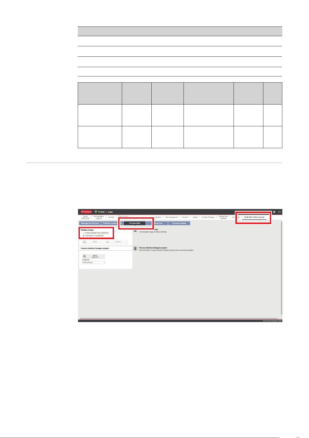
パラメータ 値 各部の名称
バスモジュールの
操作要件
ベンダー ID 0534
装置の種類 000C
製品コード 0390
hex
hex
hex
(1332
(12
dec
(912
) Fronius International GmbH
dec
) 通信アダプター
) Fronius FB Pro TwinEthernet/IP-2-Port
dec
製品名 Fronius-FB-Pro-Twin-EtherNetIP(TM)
Size
Instance
Image Type
Type
Standard Image Producin
g
Instance
Name
Input Data
Standard
Instance
Description
Data from power
source to robot
Instance
Number
105 120
[Byte
]
Instance
Consumi
ng
Instance
Output
Data
Standard
Data from robot
to power source
155 120
バスモジュールを使用する場合は、以下の要件を満たす必要があります。
1.CFG/i RI FB PRO TWIN Fanuc 1.0 オプションを両方の溶接電源に取り付けているこ
と
2.CFG/i RI FB PRO TWIN Fanuc 1.0 オプションを両方の溶接電源の SmartManager で
有効にしていること:
76
溶接電源の SnartManager
Page 77

バスモジュール IP アドレスの設定
バスモジュール IP
アドレスの設定
バスモジュールの IP アドレスは以下のよ
うに設定できます。
1.インターフェースのディップ ・スイッ
チにより 192.168.0.xx
(xx = ディップ・スイッチ設定 = 1~
63)で定義された範囲内
-
すべての位置は工場出荷時に
OFF に設定されています。この
場合、IP アドレスは溶接電源の
Web サイトで設定する必要あり
ます
2.溶接電源の Web サイト(ディップ・
スイッチのすべての位置が OFF に設
定されている場合)
ディップスイッチ位置 1~6 を使って IP アドレスを設定します。設定はバイナリ形式で
す。これは、10 進数表記の 1~63 の設定範囲になります。
インターフェースのディップ ・スイッチでバスモジュールの IP アドレスを設定する
例:
ディップ・スイッチ
JA
8 7 6 5 4 3 2 1 IP アドレス
- -
- -
- -
- -
- -
オフ オフ オフ オフ オフ オン
オフ オフ オフ オフ オン オフ
オフ オフ オフ オフ オン オン
オン オン オン オン オン オフ
オン オン オン オン オン オン
1
2
3
62
63
溶接電源の Web サイトで IP アドレスを設定する方法 (SmartManager):
使用する溶接電源の IP アドレスをメモする:
溶接電源の制御盤で、「初期設定」を選択します
1
溶接電源の制御盤で、「システム」を選択します
2
溶接電源の制御盤で、「情報」を選択します
3
表示された IP アドレス(例:10.5.72.13)を書き留めます
4
溶接電源の Web サイトにインターネットブラウザでアクセスします。
コンピューターを溶接電源のネットワークに接続します
5
インターネットブラウザの検索バーに溶接電源の IP アドレスを入力し、確認します
6
標準のユーザー名(admin)とパスワード(admin)を入力します
7
-
溶接電源の Web サイトが表示されます
バスモジュール IP アドレスの設定:
溶接電源の Web サイトで、「RI FB PRO/i TWIN」タブを選択します
8
インターフェースに対して希望の IP アドレスを「モジュール構成」に入力します。
9
例:192.168.0.12
77
Page 78

「構成の設定」を選択します
10
「モジュールの再起動」を選択します
11
-
設定した IP アドレスが適用されます
78
Page 79

入力信号および出力信号
データタイプ 次のデータ型が使用されます。
-
UINT16(符号なし整数)
0~65535 の整数
-
SINT16(符号付き整数)
-32768~32767 の整数
入力信号の利用可
能性
入力信号(ロボッ
トから溶接電源
へ)
変換例:
-
正の値(SINT16)の場合
例、必要なワイヤ供給速度 x 係数
12.3 m/分 x 100 =1230
-
負の値(SINT16)の場合
例、アーク補正 x 係数
-6.4 x 10 = -64
下記の入力信号は、RI MOD/i CC Ethernet/IP-2P TWIN FANUC のファームウェア V1.8.0
から使用可能です。
dec
=FFC0
dec
hex
=04CE
hex
JA
79
Page 80

アドレス
相対 絶対
ワード
バイト
ビット
1 1 Welding Start 増加
2 2 Robot ready High
3 3 Working mode Bit 0
ビット
信号
アクティ
ビティ
/
データタ
イプ 範囲
係数
1
1
2
4 4 Working mode Bit 1
5 5 Working mode Bit 2
6 6 Working mode Bit 3
7 7 Working mode Bit 4
8 8 —
1 9 Gas on 増加
2 10 Wire forward 増加
3 11 Wire backward 増加
4 12 Error quit 増加
5 13 Touch sensing High
6 14 Torch blow out 増加
7 15 Processline selection Bit 0 High 90 ページの次の表値
8 16 Processline selection Bit 1 High
1 17 Welding Simulation High
2 18 —
3 19 —
UINT5
(0 - 31)
90 ページの次の表
Working Mode の値範
囲を参照
の範囲 Process line
selection を参照
3
2
4
4 20 —
5 21 —
6 22 ¥ブースターマニュアル High
7 23 Wire brake on High
8 24 Torchbody Xchange High
1 25 —
2 26 Teach mode High
3 27 —
4 28 —
5 29 —
6 30 ワイヤ検知開始 High
7 31 ワイヤ検知中断 High
8 32 —
80
Page 81

アドレス
相対 絶対
ワード
バイト
ビット
ビット
信号
アクティ
ビティ
/
データタ
イプ 範囲
係数
1 33
2 34
3 35 —
5
3
6
4 36 —
5 37 —
6 38 文書モード High
7 39 —
8 40 —
1 41 —
2 42 —
3 43 —
4 44 —
5 45 —
6 46 —
Operating mode TWIN System
Bit 0
Operating mode TWIN System
Bit 1
High
High
90 ページの次の表
Operating mode TWIN
System の値の範囲を
参照
91 ページの次の表
Documentation mode
の値の範囲を参照
JA
7 47 —
8 48
Disable Arclength stabilizer,
Power source 1 + 2
High
81
Page 82

アドレス
相対 絶対
ワード
バイト
ビット
1 49 —
2 50 —
3 51 —
ビット
信号
アクティ
ビティ
/
データタ
イプ 範囲
係数
7
4
8
9
4 52 —
5 53 —
6 54 —
7 55 —
8 56 —
1 57 ExtInput1 => OPT_Output 1 High
2 58 ExtInput2 => OPT_Output 2 High
3 59 ExtInput3 => OPT_Output 3 High
4 60 ExtInput4 => OPT_Output 4 High
5 61 ExtInput5 => OPT_Output 5 High
6 62 ExtInput6 => OPT_Output 6 High
7 63 ExtInput7 => OPT_Output 7 High
8 64 ExtInput8 => OPT_Output 8 High
1 65 —
2 66 —
3 67 —
4 68 —
5 69 —
82
6 70 —
7 71 —
8 72 —
5
10
1 73
2 74 —
3 75 —
4 76 —
5 77 —
6 78 —
7 79 —
8 80 —
Contact tip short circuit
detection on
High
Page 83

アドレス
相対 絶対
ワード
バイト
ビット
1 81 —
2 82 —
3 83 —
ビット
信号
アクティ
ビティ
/
データタ
イプ 範囲
係数
JA
11
6
12
13
7
14
15
8
16
4 84 —
5 85 —
6 86 —
7 87 —
8 88 —
1 89 —
2 90 —
3 91 —
4 92 —
5 93 —
6 94 —
7 95 —
8 96 —
1~16 97~112
1~16 113~128
Welding characteristic- / Job
number、溶接電源 1
Welding characteristic- / Job
number、溶接電源 2
UINT16 0~65535 1
UINT16 0~65535 1
917、181~16 129~144
以下の溶接プロセスの場合
MIG/MAG パルスシナジー、
MIG/MAG 標準シナジー、
MIG/MAG 標準手溶接、
MIG/MAG PMC,
MIG/MAG LSC,
CMT, ConstantWire:
Wire feed speed command
value, Power source 1
ジョブモードの場合:
Power correction, Power source
1
SINT16
SINT16
-327.68~
327.67
[m/分]
-20.00~20.00
[%]
100
100
83
Page 84

アドレス
相対 絶対
ワード
バイト
1019、201~16 145~160
ビット
ビット
信号
以下の溶接プロセスの場合
MIG/MAG パルスシナジー、
MIG/MAG 標準シナジー、
MIG/MAG 標準手溶接、
MIG/MAG PMC,
MIG/MAG LSC,
CMT, ConstantWire:
Wire feed speed command
value, Power source 2
ジョブモードの場合:
Power correction, Power source
2
以下の溶接プロセスの場合
MIG/MAG パルスシナジー、
MIG/MAG 標準シナジー、
MIG/MAG PMC,
MIG/MAG LSC,
CMT:
アクティ
ビティ
/
データタ
イプ 範囲
-327.68~
SINT16
SINT16
SINT16
-20.00~20.00
-10.0~10.0
[ステップ]
327.67
[m/分]
[%]
係数
100
100
10
1121、221~16 161~176
Arclength correction, Power
source 1
以下の溶接プロセスの場合
MIG/MAG 標準手溶接:
Welding voltage, Power source 1
ジョブモードの場合:
Arclength correction, Power
source 1
以下の溶接プロセスの場合
ConstantWire:
Hotwire current, Power source 1
UINT16
SINT16
UINT16
0.0~6553.5
[V]
-10.0~10.0
[ステップ]
0.0~6553.5
[A]
10
10
10
84
Page 85

アドレス
相対 絶対
ワード
バイト
1223、241~16 177~192
ビット
ビット
信号
以下の溶接プロセスの場合
MIG/MAG パルスシナジー、
MIG/MAG 標準シナジー、
MIG/MAG PMC,
MIG/MAG LSC,
CMT:
Arclength correction, Power
source 2
以下の溶接プロセスの場合
MIG/MAG 標準手溶接:
Welding voltage, Power source 2
ジョブモードの場合:
Arclength correction, Power
source 2
アクティ
ビティ
/
データタ
イプ 範囲
SINT16
UINT16
SINT16
-10.0~10.0
[ステップ]
0.0~6553.5
-10.0~10.0
[ステップ]
[V]
係数
JA
10
10
10
1325、261~16 193~208
1427、281~16 208~223
以下の溶接プロセスの場合
ConstantWire:
Hotwire current, Power source 2
以下の溶接プロセスの場合
MIG/MAG パルスシナジー、
MIG/MAG 標準シナジー、
MIG/MAG PMC,
MIG/MAG LSC,
CMT:
Pulse-/dynamic correction,
Power source 1
以下の溶接プロセスの場合
MIG/MAG 標準手溶接:
Dynamic, Power source 1
以下の溶接プロセスの場合
MIG/MAG パルスシナジー、
MIG/MAG 標準シナジー、
MIG/MAG PMC,
MIG/MAG LSC,
CMT:
Pulse-/dynamic correction,
Power source 2
UINT16
SINT16
UINT16
SINT16
0.0~6553.5
[A]
-10.0~10.0
[ステップ]
0.0~10.0
[ステップ]
-10.0~10.0
[ステップ]
10
10
10
10
以下の溶接プロセスの場合
MIG/MAG 標準手溶接:
Dynamic, Power source 2
UINT16
0.0~10.0
[ステップ]
10
85
Page 86

アドレス
相対 絶対
ワード
バイト
ビット
ビット
信号
アクティ
ビティ
/
データタ
イプ 範囲
係数
15
16
17
18
19
20
21
22
23
29
1~16 225~240
30
31
1~16 241~256
32
33
1~16 257~272 Welding speed UINT16
34
35
1~16 273~288
36
37
1~16 289~304
38
39
1~16 305~320
40
41
1~16 321~336 Wire sense edge detection UINT16
42
43
1~16 337~352 —
44
45
1~16 353~368 —
46
Wire retract correction, Power
source 1
Wire retract correction, Power
source 2
Arclength stabilizer, Power
source 1
Arclength stabilizer, Power
source 2
Wire forward / wire backward
length
UINT16 0.0~10.0 10
UINT16 0.0~10.0 10
0.0~6535.5
[cm/分]
UINT16 0.0~5.0 10
UINT16 0.0~5.0 10
UINT16
オフ/1~65355
[mm]
オフ/0.5~20.0
[mm]
10
1
10
24
25
26
27
28
29
30
47
1~16 369~384 —
48
49
1~16 385~400 —
50
51
1~16 401~416 —
52
53
1~16 417~432 —
54
55
1~16 433~448 —
56
57
1~16 449~464 —
58
59
1~16 465~480 Seam number UINT16 0~65535 1
60
86
Page 87

アドレス
相対 絶対
ワード
バイト
ビット
ビット
信号
アクティ
ビティ
/
データタ
イプ 範囲
係数
31
61
62
1 481
2 482 —
3 483 —
4 484 —
5 485 Disable gas-settings High
6 486
7 487
8 488
1 489
2 490 —
3 491 —
4 492 —
5 493 —
Disable start-end-parameter
(Image)
Disable components setup
(TAG)
Disable language / units /
standards (TAG)
Disable penetration stabilizer,
Power source 1 + 2
Enable arc break monitoring /
arc loss
High
High
High
High
High
JA
6 494 —
7 495 —
8 496 —
87
Page 88

アドレス
相対 絶対
ワード
バイト
ビット
1 497 —
2 498 —
3 499 —
ビット
信号
アクティ
ビティ
/
データタ
イプ 範囲
係数
32
33
34
63
64
65
66
67
68
4 500 —
5 501 —
6 502 —
7 503 —
8 504 —
1 505 —
2 506 —
3 507 —
4 508 —
5 509 —
6 510 —
7 511 Command value selection Bit 0 High 91 ページの次の表
Command value
8 512 Command value selection Bit 1 High
1~16 513~528 TAG start address UINT16 1~65535 1
1~16 529~544 TAG value 1
selection の値の範囲を
参照
69
35
36
37
38
39 77 1~8 609~616 TAG quantity UINT8 0~5 1
39 78 1 617 TAG command read 増加
39 78 2 618 TAG command write 増加
39 78 3~8 619~624 —
40
88
1~16 545~560 TAG value 2
70
71
1~16 561~576 TAG value 3
72
73
1~16 577~592 TAG value 4
74
75
1~16 593~608 TAG value 5
76
79
1~16 625~640 Gas preow UINT16
80
0.0~9.9
[s]
10
Page 89

アドレス
相対 絶対
ワード
バイト
ビット
ビット
信号
アクティ
ビティ
/
データタ
イプ 範囲
係数
41
42
43
44
45
46
47
48
81
1~16 641~656 Gas postow UINT16
82
83
1~16 657~672 Inching value UINT16
84
85
1~16 673~688 S2T - Starting current UINT16
86
87
1~16 689~704 S2T - Starting current 時間 UINT16
88
89
1~16 705~720 S2T - Slope 1 UINT16
90
91
1~16 721~736 S2T - Slope 2 UINT16
92
93
1~16 737~752 S2T - End current UINT16
94
95
1~16 753~768 S2T - End current 時間 UINT16
96
0.0~9.9
[s]
-327.67~
327.67
[m/分]
0.0~200
[%]
0.0~9.9
[s]
0.0~9.9
[s]
0.0~9.9
[s]
0.0~200
[%]
0.0~9.9
[s]
10
JA
100
1
10
10
10
1
10
49
50
51
52
53
54
55
56
97
98
99
100
101
102
103
104
105
106
107
108
109
110
111
112
1~16 769~784 Start arclength correction SINT16 -10.0~10.0 10
1~16 785~800 End arclength correction UINT16 -10.0~10.0 10
91 ページの次の表値
1~16 801~816 Pulse synchronization ratio UINT16
1~16 817~832 Phase shift lead / trail UINT16
1~16 833~848 Ignition delay trail UINT16
1~16 849~864 —
1~16 865~880
1~16 881~896
Penetration stabilizer,
Power source 1
Penetration stabilizer,
Power source 2
UINT16
UINT16
の範囲 Pulse
synchronization ratio
を参照
0~95
(255 = AUTO)
0.00~2.00
(254 = OFF)
(255 = OFF)
0.0~10.0
[m/分]
0.0~10.0
[m/分]
1
100
10
10
89
Page 90

ワード
57
58
59
60
アドレス
相対 絶対
バイト
ビット
113
1~16 897~912 —
114
115
1~16 913~928 —
116
117
1~16 929~944 —
118
119
1~16 945~960 —
120
ビット
信号
アクティ
ビティ
/
データタ
イプ 範囲
係数
Working Mode の
値範囲
値の範囲 Process
line selection
ビッ
ト 4
ビッ
ト 3
ビッ
ト 2
ビッ
ト 1
ビッ
ト 0 説明
0 0 0 0 0 内部パラメータ選択内容
0 0 0 0 1 特別な 2 ステップモードの特性
0 0 0 1 0 ジョブモード
0 1 0 0 0 2 ステップモードの特性
0 1 0 0 1 2-ステップ MIG/MAG 標準手溶接
1 0 0 0 1 冷却液ポンプの停止
操作モードの値範囲
Bit 1 Bit 0 説明
0 0 加工ライン 1(default)
0 1 加工ライン 2
1 0 加工ライン 3
1 1 予備
加工ライン選択の値の範囲
Operating mode
TWIN System の値
の範囲
90
ビット 1 ビット 0 機能溶接電源 1 機能溶接電源 2
0 0 Single mode OFF
0 1 TWIN Lead TWIN Trail
1 0 TWIN Trail TWIN Lead
Page 91

ビット 1 ビット 0 機能溶接電源 1 機能溶接電源 2
1 1 OFF Single mode
TWIN システムモードの値の範囲
Documentation
mode の値の範囲
Wertebereich
Process
controlled
correction
Command value
selection の値の範
囲
ビット 0 各部の名称
0 溶接電源の溶接シーム番号(内部)
1 ロボットのシーム番号(Word 29)
文書モードの値の範囲
プロセス
信号
PMC アーク長さ安定材 SINT16
プロセス依存修正の値範囲
ビッ
ト 1
ビッ
ト 0 各部の名称
0 0 ワイヤ供給速度コマンド値
データタイプ
アクティビティ/
-327.8~+327.7
値の範囲
設定範囲
単位
0.0~+5.0 ボルト 10
JA
係数
値の範囲
Pulse
synchronization
ratio
0 1 溶接電流指令値
信号 Command value selection の値の範囲
値 各部の名称
1 自動
2 1/1
3 1/2
4 1/3
値の範囲 Pulse synchronization ratio
91
Page 92

出力信号の利用可
能性
出力信号(溶接電
源からロボット
へ)
アドレス
相対 絶対
ワード
バイト
下記の出力信号は、RI MOD/i CC Ethernet/IP-2P TWIN FANUC のファームウェア V1.8.0
から使用可能です。
アクティビ
ティ
ビット
1 1 Heartbeat Powersource 高/低 1 Hz
2 2 Power source ready 高
3 3 Warning 高
ビット
信号
/
データタイ
プ 範囲
係数
1
1
2
4 4 Process active 高
5 5 Current ow 高
6 6 Arc stable- / touch signal 高
7 7 Main current signal 高
8 8 Touch signal 高
1 9 Collisionbox active 低
2 10
3 11 Wire stick workpiece High
4 12 —
5 13 Short circuit contact tip High
6 14 Parameter selection internally High
7 15 —
8 16 Torch body gripped 高
ロボット動作リリース、溶接電
源 1
高
0 = 衝突または
ケーブル断線
92
Page 93

アドレス
相対 絶対
ワード
バイト
ビット
1 17 Command value out of range 高
2 18 Correction out of range 高
3 19 —
ビット
信号
アクティビ
ティ
/
データタイ
プ 範囲
係数
JA
3
2
4
5
4 20 Limitsignal、溶接電源 1 高
5 21 —
6 22 Standby active 高
7 23 Main supply status 高
8 24 —
1 25 Sensor status 1、溶接電源 1 高
2 26 Sensor status 2、溶接電源 1 高
3 27 Sensor status 3、溶接電源 1 高
4 28 Sensor status 4、溶接電源 1 高
5 29 —
6 30 —
7 31 —
8 32 —
1 33 —
2 34 —
3 35 —
4 36 Safety status Bit 0、溶接電源 1 高
5 37 Safety status Bit 1、溶接電源 1 高
99 ページの表センサ
ーステータスの割り当
て 1~4 を参照
99 ページの表値範囲
Safety status を参照
6 38 —
7 39 Notication 高
3
6
8 40 System not ready 高
1 41 —
2 42 —
3 43 —
4 44 —
5 45 —
6 46 —
7 47 —
8 48 —
93
Page 94

アドレス
相対 絶対
ワード
バイト
ビット
1 49 —
2 50 —
3 51 —
ビット
信号
アクティビ
ティ
/
データタイ
プ 範囲
係数
7
4
8
4 52 —
5 53 —
6 54 —
7 55 Gas nozzle touched 高
8 56 —
1 57 ExtOutput1 <= OPT_Input1 高
2 58 ExtOutput2 <= OPT_Input2 高
3 59 ExtOutput3 <= OPT_Input3 高
4 60 ExtOutput4 <= OPT_Input4 高
5 61 ExtOutput5 <= OPT_Input5 高
6 62 ExtOutput6 <= OPT_Input6 高
7 63 ExtOutput7 <= OPT_Input7 高
8 64 ExtOutput8 <= OPT_Input8 高
1 65 —
2 66
3 67 Limitsignal, Power source 2 高
Robot Motion Release, Power
source 2
高
9
5
10
4 68 —
5 69 —
6 70 —
7 71 —
8 72 —
1 73 —
2 74 —
3 75 —
4 76 —
5 77 —
6 78 —
7 79 —
8 80 —
94
Page 95

アドレス
相対 絶対
ワード
バイト
11
ビット
1 81 Sensor status 1、溶接電源 2 高
2 82 Sensor status 2、溶接電源 2 高
3 83 Sensor status 3、溶接電源 2 高
4 84 Sensor status 4、溶接電源 2 高
5 85 —
6 86 —
7 87 —
ビット
信号
アクティビ
ティ
/
データタイ
プ 範囲
99 ページの表センサ
ーステータスの割り当
て 1~4 を参照
係数
JA
6
7
8
9
10
8 88 —
1 89 —
2 90 —
3 91 —
4 92 Safety status Bit 0、溶接電源 2 高
12
5 93 Safety status Bit 1、溶接電源 2 高
6 94 —
7 95 —
8 96 —
13
0~16 97~112
14
15
0~16 113~128
16
17
0~16 129~144
18
19
0~16 145~160
20
Real value welding voltage,
Power source 1
Real value welding voltage,
Power source 2
Real value welding current,
Power source 1
Real value welding current,
Power source 2
99 ページの表値範囲
Safety status を参照
UINT16 0.0~655.35 [V] 100
UINT16 0.0~655.35 [V] 100
UINT16 0.0~6535.5 [A] 10
UINT16 0.0~6535.5 [A] 10
11
12
13
14
15
21
0~16 161~176
22
23
0~16 177~192
24
25
0~16 193~208
26
27
0~16 209~224 Error number, Power source 1 UINT16 0~65535 1
28
29
0~16 225~240 Error number、溶接電源 2 UINT16 0~65535 1
30
Real value wire feed speed,
Power source 1
Real value wire feed speed,
Power source 2
Actual real value for seam
tracking
SINT16
SINT16
UINT16 0~6,5535
-327.68~
327.67
[m/分]
-327.68~
327.67
[m/分]
100
100
1000
0
95
Page 96

アドレス
相対 絶対
ワード
バイト
ビット
ビット
信号
アクティビ
ティ
/
データタイ
プ 範囲
係数
16
17
18
19
20
21
22
23
24
31
0~16 241~256
32
33
0~16 257~272
34
35
0~16 273~288
36
37
0~16 289~304
38
39
0~16 305~320
40
41
0~16 321~336
42
43
0~16 337~352 Warning, Power source 1 UINT16 0~65535 1
44
45
0~16 353~368 Warning, Power source 2 UINT16 0~65535 1
46
47
0~16 369~384 Wire position, Power source 1 SINT16
48
Motor current M1, Power
source 1
Motor current M1, Power
source 2
Motor current M2, Power
source 1
Motor current M2, Power
source 2
Motor current M3, Power
source 1
Motor current M3, Power
source 2
UINT16 0~655.35 [A] 100
UINT16 0~655.35 [A] 100
UINT16 0~655.35 [A] 100
UINT16 0~655.35 [A] 100
UINT16 0~655.35 [A] 100
UINT16 0~655.35 [A] 100
-327.68~
327.67 [mm]
100
25
26
27
28
29
30
49
0~16 385~400 Wire position, Power source 2 SINT16
50
51
0~16 401~416 —
52
53
0~16 417~432 —
54
58
0~16 433~448 —
56
57
0~16 449~464 —
58
59
0~16 465~480 —
60
-327.68~
327.67 [mm]
100
96
Page 97

アドレス
相対 絶対
ワード
バイト
ビット
1 481 —
2 482 —
3 483 —
ビット
信号
アクティビ
ティ
/
データタイ
プ 範囲
係数
JA
31
61
4 484 —
5 485 —
6 486 —
7 487 —
8 488 —
1 489 —
2 490 —
3 491 —
4 492 —
62
5 493 —
6 494 —
7 495 —
8 496 —
1 497 —
2 498 —
3 499 —
4 500 —
63
5 501 —
32
33
6 502 —
7 503 —
8 504 —
1 505 —
2 506 —
3 507 —
4 508 —
64
5 509 —
6 510 —
7 511 —
8 512 —
65
1~16 513~528 TAG start address UINT16 1~65535 1
66
97
Page 98

アドレス
相対 絶対
アクティビ
ティ
ワード
バイト
67
34
68
69
35
70
71
36
72
73
37
74
75
38
76
39 77 0~7 609~616 TAG quantity UINT8 1~255
ビット
1~16 529~544 TAG value 1
1~16 545~560 TAG value 2
1~16 561~576 TAG value 3
1~16 577~592 TAG value 4
1~16 593~608 TAG value 5
ビット
信号
/
データタイ
プ 範囲
係数
39 78 0 617 TAG command read 増加
39 78 1 618 TAG command write 増加
39 78 2~7 619~624 —
79
40
41
42
43
44
~
45
46
~
47
48
1~16 625~640 Cooler temperature UINT16
80
81
1~16 641~656 Cooler ow rate UINT16
82
83
1~16 657~672
84
85
1~16 673~688
86
87
~901~32 689~720
91
~941~32 721~752
95
1~16 753~768
96
Real energy value, Power
source 1
Power on value, Power source
1
Hour meter power on, Power
source 1
Hour meter arc on time, Power
source 1
Real energy value, Power
source 2
UINT16
UINT16
UINT32
UINT32
UINT16
-100~200
[°C]
-100~100
[l/分]
0.0~6535.5
[kJ]
0.0~6535.5
[kW]
0~100000 [時
間]
0~100000 [時
間]
0.0~6535.5
[kJ]
10
10
10
10
10
10
10
98
49
50
~
51
93
94
99
~
102
1~16 769~784
1~32 785~816
Power on value, Power source
2
Hour meter power on, Power
source 2
UINT16
UINT32
0.0~6535.5
[kW]
0~100000 [時
間]
10
10
Page 99

ワード
52
~
53
54
55
56
57
58
アドレス
相対 絶対
バイト
103
~
106
107
108
109
110
111
112
113
114
115
116
ビット
1~32 817~848
1~16 849~864 —
1~16 865~880 —
1~16 881~896 —
1~16 897~912 —
1~16 913~928 —
ビット
信号
Hour meter arc on time, Power
source 2
アクティビ
ティ
/
データタイ
プ 範囲
UINT32
0~100000 [時
間]
係数
10
JA
117
59
118
119
60
120
センサーステータ
スの割り当て 1~4
値範囲 Safety
status
1~16 929~944 —
1~16 945~960 —
信号 説明
Sensor status 1 OPT/i WF R ワイヤ端 (4,100,869)
Sensor status 2 OPT/i WF R ワイヤドラム (4,100,879)
Sensor status 3 OPT/i WF R リングセンサー (4,100,878)
Sensor status 4 ワイヤバッファセット CMT TPS/i (4,001,763)
ビッ
ト 1
0 0 予備
ビッ
ト 0 説明
0 1 保持
1 0 停止
1 1 未インストール / アクティブ
99
Page 100

TAG テーブル
アドレス TAG
アクティビ
ティ/
データタイ
プ
範囲 係数
BIT 481 Disable Start-end-
parameter:
TAG 1 —
TAG 2 —
TAG 3 —
TAG 4 —
TAG 5 —
アドレス TAG
BIT 482
TAG 6 —
TAG 7 —
TAG 8 —
TAG 9 —
アドレス TAG
高
アクティビ
ティ/
データタイ
プ
アクティビ
ティ/
データタイ
プ
範囲 係数
範囲 係数
BIT 483
TAG 10 —
TAG 11 —
TAG 12 —
TAG 13 —
TAG 14 —
TAG 15 —
TAG 16 —
TAG 17 —
TAG 18 —
TAG 19 —
アクティビ
ティ/
データタイ
アドレス TAG
BIT 484
TAG 20 —
プ
範囲 係数
100
 Loading...