

Page 1

/ Battery Charging Systems / Welding Technology / Solar Electronics
St andkonsole
Base stand
Console sur pieds
Montageanleitung
DEENPT-BR
Systemerweiterung
Fitting Instruction
System extension
Instructions de montage
FR
Extension système
42,0410,0854 003-25032013
Page 2

2
Page 3

Montageanleitung: Standkonsole für TS 4000/5000,
TPS 2700/4000/5000
DE
Einleitung
Merkmale der
Standkonsole
Die Standkonsole für die digitale Geräteserie kommt vor allem bei Roboteranwendungen zum Einsatz und wird unter dem Kühlgerät oder der Stromquelle eingebaut. Die
Stromquelle wird dadurch höher gestellt, was eine geringere Verschmutzungsgefahr
und eine angenehmere Bedienhöhe zur Folge hat.
Warnung! Fehlerhaft durchgeführte Arbeiten können schwerwiegende Sach- und
Personenschäden verursachen. Nachfolgend beschriebene Tätigkeiten dürfen
nur von Fronius-geschultem Fachpersonal durchgeführt werden! Beachten Sie
die Sicherheitsvorschriften in der Bedienungsanleitung der Stromquelle.
- Geringerer Platzbedarf als ein Fahrwagen
- Robuste Bodenmontage der Stromquelle möglich (z.B. für Roboterzellen)
- Schlitze für Staplertransport
- Verbinden von mehreren Standkonsolen mittels Verbindungsschrauben möglich
(z.B. für TPS 9000)
- Montage der Schlauchpaket-Zugentlastung möglich
- Räder mit Feststellbremse als Option
- Kranösen als Option
a) zum Krantransport von zwei verschraubten Standkonsolen
b) zur zusätzlichen Versteifung von zwei verschraubten Standkonsolen
Hinweis! Die Standkonsole ist nicht ausgelegt für
- eine Gasflaschenhalterung,
- die Aufnahme eines Drahtvorschubes.
max. 10°
max. 940 mm
(max. 3ft. 1in.)
Warnung! Eine umstürzende
Schweißanlage kann Lebensgefahr
bedeuten. Bei Montage und Aufstellung der Standkonsole einen
Neigungswinkel von 10° nicht
überschreiten.
Warnung! Eine umstürzende
Schweißanlage kann Lebensgefahr
bedeuten. Ab einer Bauhöhe von
940 mm (3ft. 1in.) ist eine fixe
Montage der S tandkonsole am
Boden erforderlich.
3
Page 4
Erforderliche
Werkzeuge
SW19
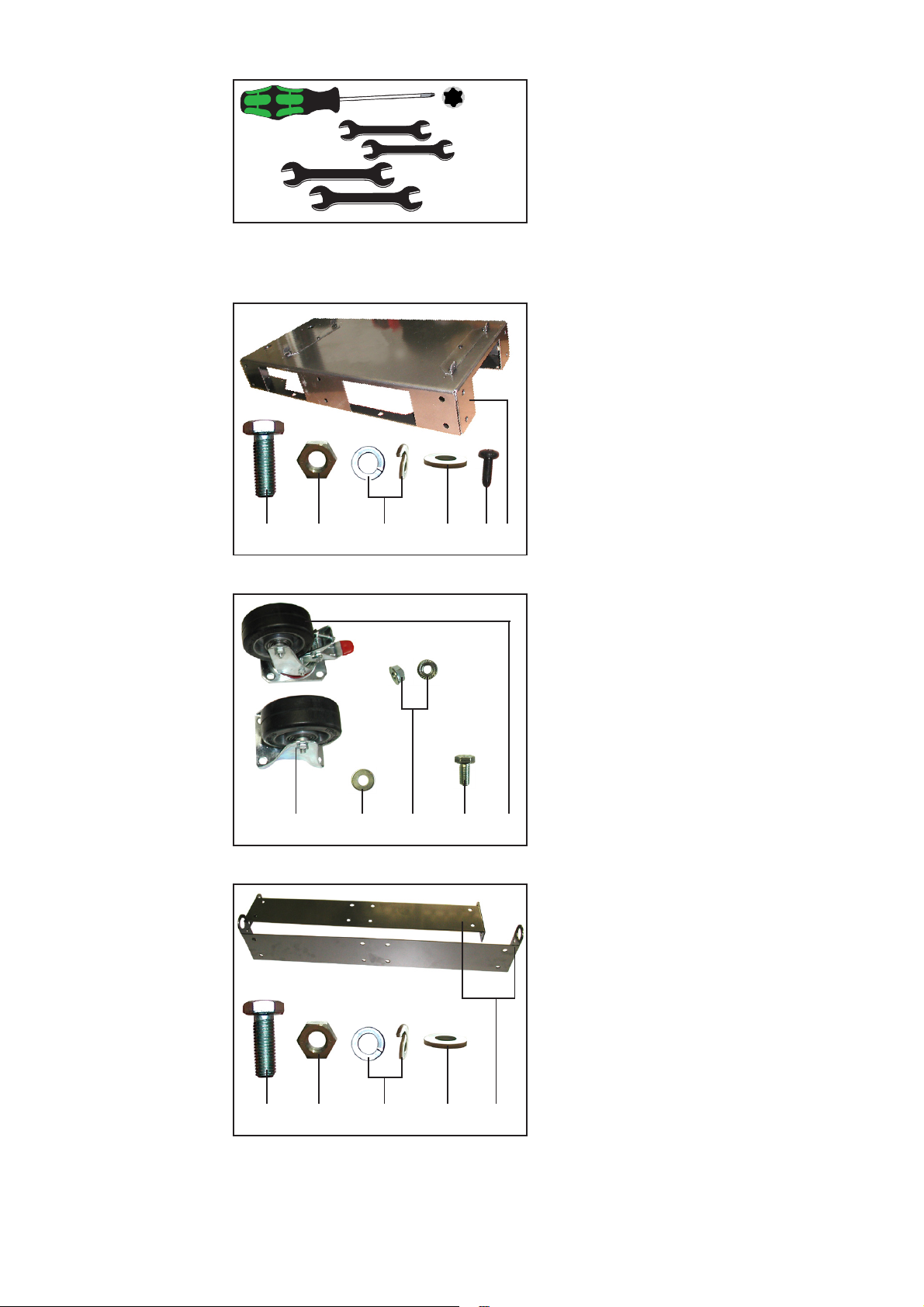
Abb.1 Werkzeuge
T20
SW13
- 1 Stk. Hand-Schraubendreher, T20
- 2 Stk. Gabelschlüssel, Schlüsselweite
13 mm ... zur Montage der Rollen
- 2 Stk. Gabelschlüssel, Schlüsselweite
19 mm ... zur Montage von Standkonsolen aneinander
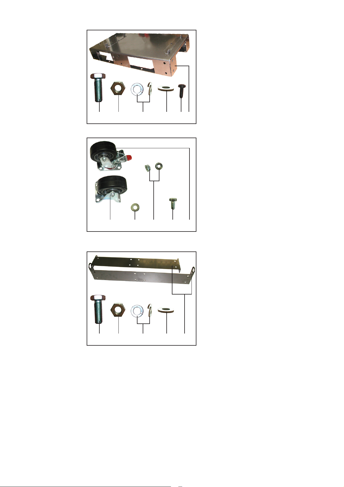
Bauteile/Artikelnummern
Standkonsole............................. 4,045,881
bestehend aus
(1) 1 Stk. Standkonsole inkl. Montage-
blech
(2) 4 Stk. Extrude-Tite-Schrauben 5x16
(3) 3 Stk. Sechskantschrauben M12x30
(4) 3 Stk. Sechskantmuttern M12
(5) 6 Stk. Beilagsscheiben A12
(6) 3 Stk. Federringe
(1)(6) (5)(4)(3) (2)
Abb.2 Standkonsole
Option Einbauset
Radbremse Standkonsole......... 4,100,340
bestehend aus
(7) 2 Stk. Stahl-Bockrollen, 100 KL 128
(8) 2 Stk. Stahl-Lenkrollen, 100 KL 128
(9) 16 Stk. Sechskantschrauben M8x16
(10) 16 Stk. Tensilock-Sechskantmuttern
M8
(11) 16 Stk. Beilagscheiben A8
(7)
Abb.3 Einbauset Radbremse Standkonsole
(11) (9)(10)
(12)(15) (16)(14)(13)
Abb.4 Einbauset Kranöse für 2-Standkonsolen
4
(8)
Option Einbauset
Kranöse für 2-Standkonsolen.... 4,100,364
bestehend aus
(12) 2 Stk. Kranaufnahme
(13) 24 Stk. Sechskantschrauben M12x30
(14) 24 Stk. Sechskantmuttern M12
(15) 24 Stk. Federringe
(16) 48 Stk. Beilagsscheiben A12
Page 5
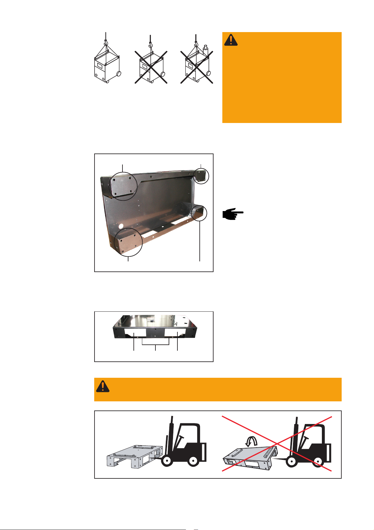
Montage Standkonsole
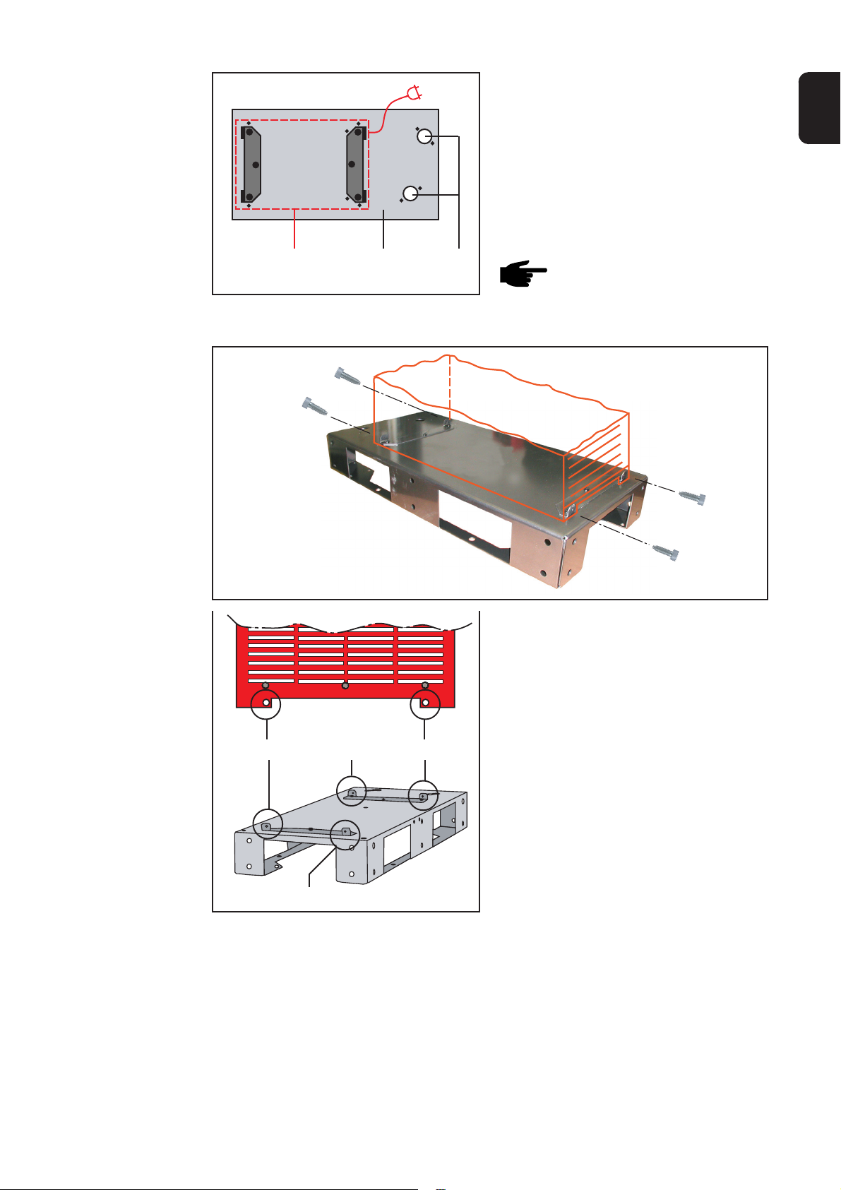
1. Stromquelle oder Kühlgerät (A) gemäß
Abbildung auf der Standkonsole (B)
aufsetzen:
- Stromquelle ... Netzkabelseite in
Richtung der Bohrungen für die
Schlauchpaket-Zugentlastung (C)
- Kühlgerät ... Anschlüsse für Kühlmittel in Richtung der Bohrungen
für die Schlauchpaket-Zugentlastung (C)
DE
(B)(A)
Abb.5 Position von Stromquelle/Kühlgerät auf der
Standkonsole
(C)
Hinweis! Die Kunststoff-Füße
des zu montierenden Gerätes
müssen außerhalb der Befestigungswinkel der Standkonsole
sein.
2. Stromquelle/Kühlgerät mittels Handschraubendreher und der 4 ExtrudeTite-Schrauben an den vorgesehenen
Stellen (D) mit der Standkonsole
verschrauben
(D)
(D)
(D)
Abb.6 Montage der S tandkonsole
3. Überprüfen Sie, ob die Schrauben fest
angezogen sind
(D)
5
Page 6

Montage Einbauset Radbremse
(Option)
Mit dem Einbauset Radbremse kann die Standkonsole beweglich gemacht werden. Die
Bremsrollen dienen zur Sicherung gegen unbeabsichtigtes Verschieben.
Warnung! Eine umstürzende Schweißanlage kann Lebensgefahr bedeuten. Bei
Montage des Einbausets Radbremse darf kein Gerät auf der Standkonsole sein!
Vorgehensweise bei Neuanschaffung:
1. Zuerst das Einbauset Radbremse montieren,
2. Anschließend Stromquelle/Kühlgerät auf die Standkonsole montieren.
Vorgehensweise beim Nachrüsten von bestehenden Standkonsolen:
1. Stromquelle und/oder Kühlgerät von der Standkonsole entfernen
2. Einbauset Radbremse montieren
3. Stromquelle und/oder Kühlgerät wieder auf der Standkonsole montieren
Warnung! Eine umstürzende Schweißanlage kann Lebensgefahr bedeuten. Die
Schweißanlage in Verbindung mit der Drehzapfenaufnahme weist eine hohe
Schwerpunktlage auf, wenn an der Standkonsole Räder montiert sind. In Verbindung mit der Drehzapfenaufnahme die Standkonsole nicht mit dem Einbauset
Radbremse versehen.
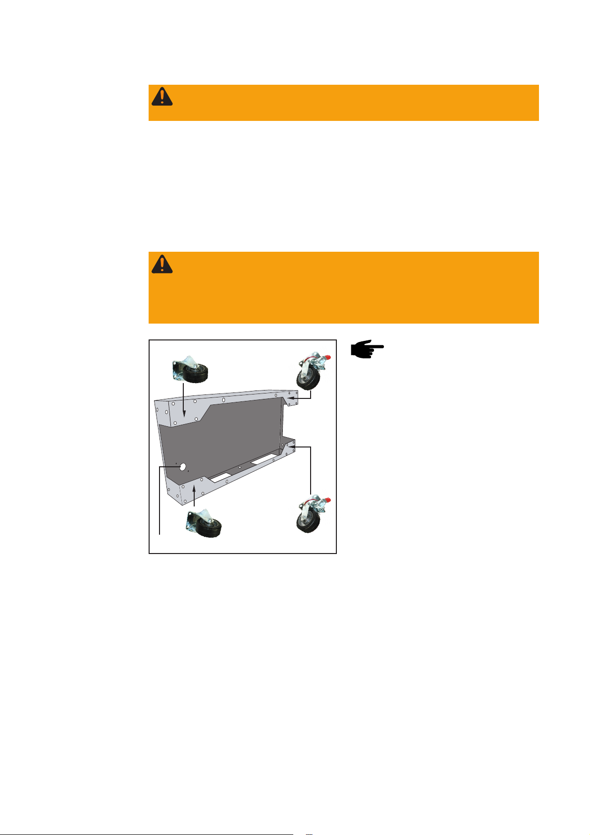
Bockrolle
(E)
Abb.7 Position der Rollen auf der Standkonsole
Bockrolle
Lenkrolle
Lenkrolle
Hinweis! Bockrollen auf der
Seite mit den Bohrungen für die
Schlauchpaket-Zugentlastung (E)
montieren.
6
Page 7
Montage Einbauset Radbremse
(Option)
Detail X
Detail X - Ansicht
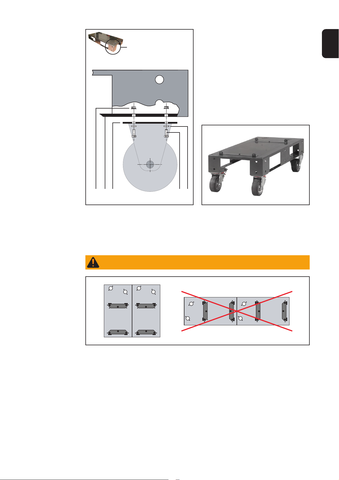
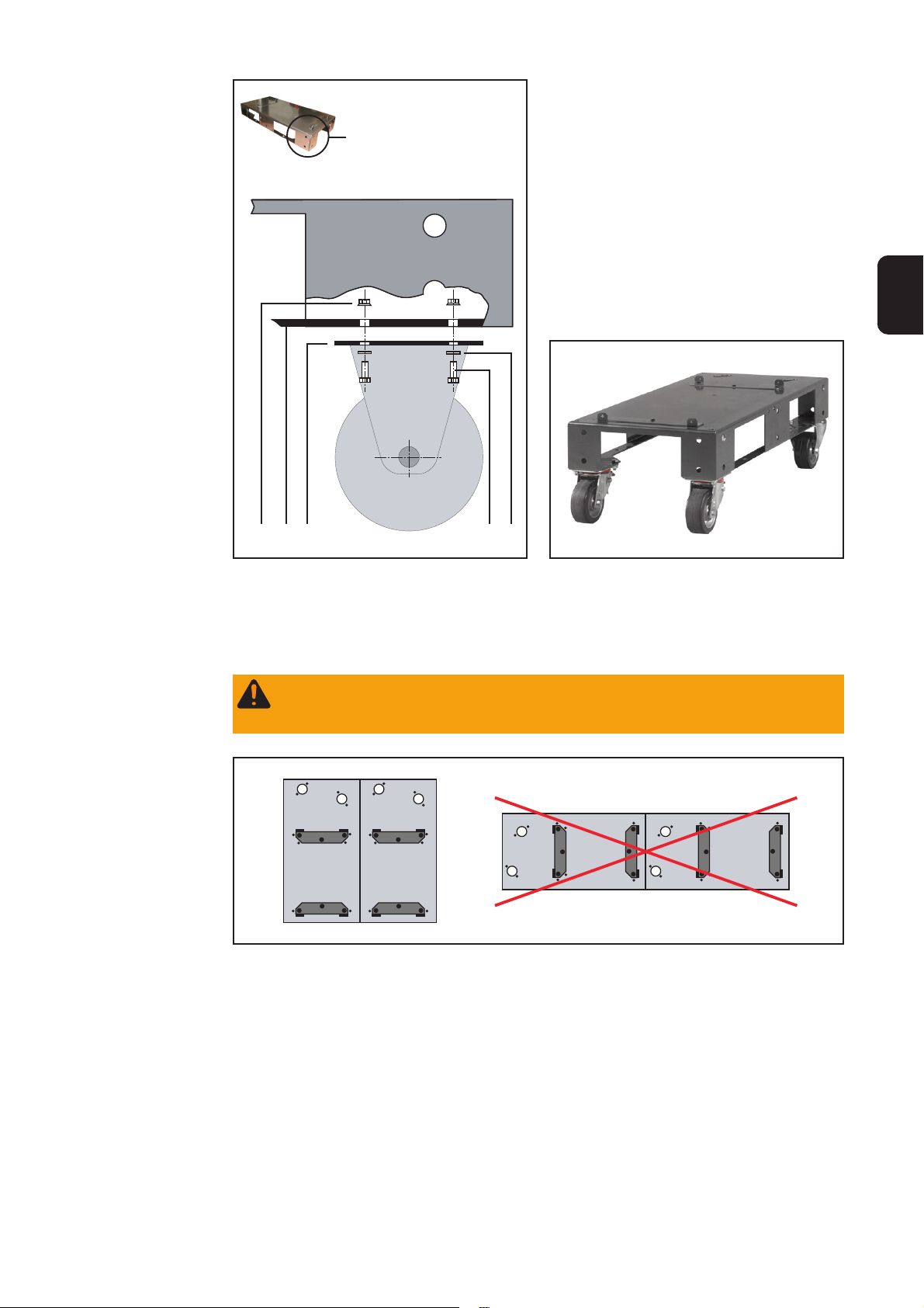
1. 16 x Beilagscheibe (11) auf Sechskantschraube (9) aufsetzen
2. Räder aufsetzen, Bohrungen in der
Radbasis (F) mit den Bohrungen in
der Standkonsole (G) übereinanderlegen
3. Schraube mit Beilagscheibe durch die
Bohrungen stecken
4. Tensilock-Sechskantmutter (10) auf
der Innenseite aufschrauben
5. Schrauben und Muttern festziehen,
Schraubverbindung auf festen Sitz
überprüfen
DE
Montage von
Standkonsolen
aneinander
(F)(G)(10) (9)
Abb.8 Montage der Rollen Abb.9 Standkonsole mit Einbauset Radbremse
(11)
Mit den beiliegenden Sechskantschrauben M12x30 können mehrere Standkonsolen
miteinander verschraubt werden.
Warnung! Eine umstürzende Schweißanlage kann Lebensgefahr bedeuten. Aus
Stabilitätsgründen Standkonsolen nur an der Längsseite zusammenschrauben!
Abb.10 Anordnung der Standkonsolen bei Montage aneinander
7
Page 8
Montage von
Standkonsolen
aneinander
(Fortsetzung)
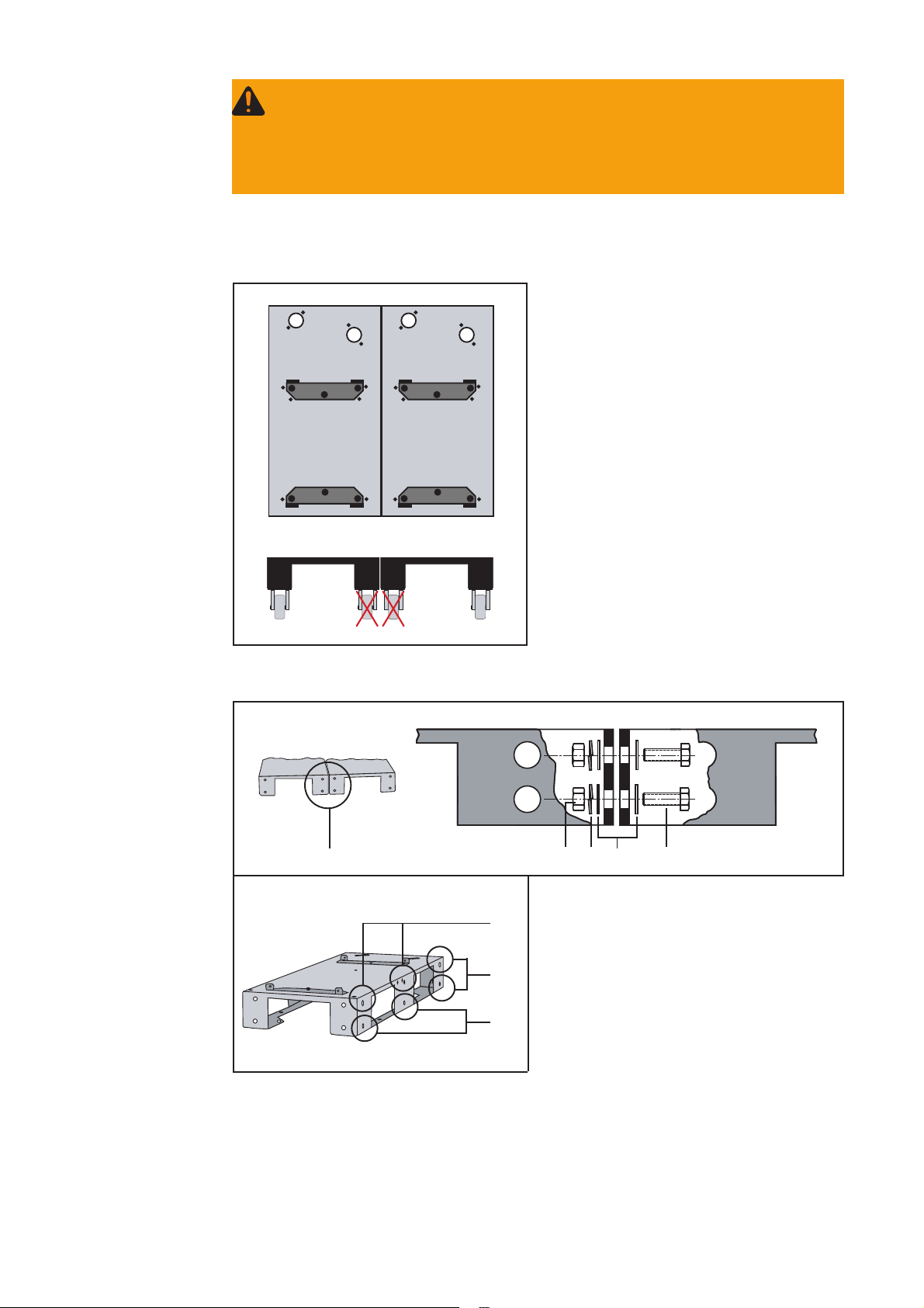
Warnung! Bei Montage von Standkonsolen aneinander
a) darf kein Gerät auf der Standkonsole sein,
b) dürfen die Räder der Option Radbremse nur montiert werden:
- in Verbindung mit der Option Einbauset „Kranöse für 2 Standkonsolen“
- nur an den äußeren Ecken der Einheit, bestehend aus zwei verbundenen
Standkonsolen
Vorgehensweise bei Neuanschaffung:
1. Zuerst die Standkonsolen aneinander montieren,
2. Anschließend Stromquelle/Kühlgerät auf die Standkonsolen montieren.
Vorgehensweise, wenn bestehende
Standkonsolen aneinander montiert
werden sollen:
1. Stromquelle und/oder Kühlgerät von
den Standkonsolen entfernen
2. Standkonsolen aneinander montieren
3. Stromquelle und/oder Kühlgerät
wieder auf die Standkonsolen montieren
Abb.11 Option Radbremse nur in Verbindung mit
Einbauset „Kranöse für 2 Standkonsolen“
Detail Y - Ansicht
Standkonsole 2
Detail Y
Standkonsole 1
(6)
(5)
(3)(4)
Montageschritte:
(H)
1. Beilagscheiben (5) auf Sechskant-
schrauben (3) aufsetzen
2. Standkonsolen nebeneinander aus-
(H)
richten, Bohrungen auf gleiche Höhe
bringen
(H)
3. Schrauben mit Beilagscheiben durch
die vorgesehenen 6 Bohrungen (H)
stecken
Abb.12 Montage von Standkonsolen aneinander
4. Beilagscheiben (5) auf Sechskant-
schrauben aufsetzen
5. Federringe (6) auf Sechskantschrau-
ben (3) aufsetzen
6. Sechskantmuttern (4) auf Sechskantschrauben (3) aufschrauben
7. Schrauben und Muttern festziehen, Schraubverbindung auf festen Sitz überprüfen
8
Page 9

Montage Einbauset Kranöse
(Option)
Mit dem Einbauset Kranöse können zwei aneinandermontierte Standkonsolen mit
einem Kran transportiert werden. Gleichzeitig dienen die Kranaufnahmen als zusätzliche Versteifung der Standkonsolen.
Warnung! Eine herabfallende Schweißanlage kann Lebensgefahr bedeuten. Bei
Montage des Einbausets Kranöse darf
a) keine Gerät auf der Standkonsole sein
b) keine Option Radbremse montiert sein.
Vorgehensweise bei Neuanschaffung:
1. Standkonsolen aneinander montieren,
2. Einbauset Kranöse montieren.
3. Stromquellen und/oder Kühlgeräte auf die Standkonsolen montieren.
Vorgehensweise beim Nachrüsten an bestehenden Standkonsolen:
1. Stromquellen und/oder Kühlgeräte von den Standkonsolen entfernen
2. Standkonsolen aneinander montieren
3. Einbauset Kranöse montieren
4. Stromquellen und/oder Kühlgeräte wieder auf den Standkonsolen montieren
DE
(13)
(13) (13)
Abb.13 Montage der Kranaufnahme
(13) (13)
(13)
Detail Z
(13)
(13)
Detail Z - Ansicht
(13)(16)(16)(15)(14)
Montageschritte:
1. Beilagscheiben (16) auf Sechskantschrauben (13) aufsetzen
2. Kranaufhängung an Standkonsolen ausrichten, Bohrungen auf gleiche Höhe bringen
3. Schrauben mit Beilagscheiben durch die vorgesehenen Bohrungen stecken
4. Beilagscheiben (16) auf Sechskantschrauben aufsetzen
5. Federringe (15) auf Sechskantschrauben (13) aufsetzen
6. Sechskantmuttern (14) auf Sechskantschrauben (13) aufschrauben
7. Schrauben und Muttern festziehen, Schraubverbindung auf festen Sitz überprüfen
Aufkleber mit
Warnhinweisen
Der Option Kranöse liegt ein Aufkleber mit Warnhinweisen bei. Den Aufkleber an der
abgebildeten Position aufkleben.
9
Page 10
Krantransport
Warnung! Eine herabfallende
Schweißanlage kann Lebensgefahr
bedeuten. Bei Montage des Ein-
bausets Kranöse
a) Ketten bzw. Seile an allen vier
Aufhängungspunkten der
Option Kranöse einhängen
b) Ketten bzw. Seile in einem
möglichst geringen Winkel zur
Senkrechten führen
c) Gasflasche und Drahtvorschub
abnehmen
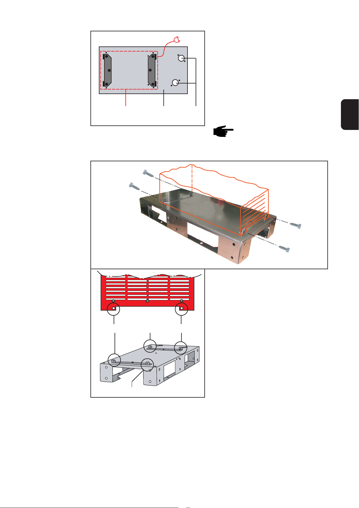
Bodenmontage
Staplertransport
(I)
(I)
Abb.14 Befestigung am Boden über Bohrungen zur
Rollenmontage
(J)
Abb.15 Öffnungen für den Staplertransport
(K)
(J)
(I)
(I)
Die Standkonsole ist auch für die Bodenmontage geeignet.
Eine Schraubverbindung zwischen Boden
und Standkonsole ist nicht erforderlich,
kann aber über die Bohrungen zur Rollenmontage (I) erfolgen.
Hinweis! Ausreichende Platzverhältnisse gewährleisten:
a) für Wartungs- und Service-
Arbeiten an den aufgebauten
Geräten,
b) für eine ausreichende Luftzir
kulation zur Gerätekühlung,
c) um eine gegenseitige Beein
flussung von Stromquellen
untereinander zu vermeiden.
Die breiten Öffnungen (J) an der Längsseite der Standkonsole ermöglichen den
Transport mit einem Stapler.
Die Querverstrebung (K) sorgt für die
notwendige Stabilität beim Transport, d.h.,
Standkonsolen können auch mit aufgebauten Geräten transportiert werden.
Warnung! Eine umstürzende Schweißanlage kann Lebensgefahr bedeuten.
Standkonsole nicht von der Stirnseite auf die Staplergabel aufnehmen, nur von
der Längsseite!
Abb.16 Staplertransport
10
Page 11

Staplertransport
(Fortsetzung)
Beispiele von
Anwendungsmöglichkeiten
Warnung! Eine umstürzende Schweißanlage kann Lebensgefahr bedeuten. Aus
Stabilitätsgründen dürfen nur maximal 2 miteinander verschraubte Standkonsolen
mit dem Stapler transportiert und bewegt werden!
DE
Abb.17 TPS 9000 auf Standkonsole, Bodenmontage
Abb.18 TPS4000 auf Standkonsole mit Option
Radbremse
11
Page 12

Fitting instructions: Base stand for TS 4000/5000,
TPS 2700/4000/5000
Introduction
Features of the
base stand
The base stand for the digital series of machines is used mainly for robot applications,
and is fitted beneath the cooling unit or the power source. By raising the power source
further off the ground, this reduces the risk of soiling and makes for a more ergonomical
operating height.
Warning! Work that is not carried out correctly can cause serious injury and
damage. The actions described below may ONLY be carried out by skilled,
Fronius-trained technicians! Observe and follow the safety rules in the Operating
Instructions for the power source.
- Takes up less space than a trolley
- Makes it possible for the power source to be sturdily floor-mounted (e.g. for robot
cells)
- Has slots so that it can be picked up and transported by fork-lift truck
- Several base stands can be linked together using connection bolts (e.g. for TPS
9000)
- Hosepack strain-relief device can be mounted
- Wheels with fixing brakes are available as an option
- Optional crane hoisting lugs:
a) for hoisting two bolted-together base stands by crane
b) for additional stiffening of two bolted-together base stands
Note! The base stand is not designed to be used:
- with a gas-cylinder holder
- for holding a wirefeeder unit.
max. 10°
max. 940 mm
(max. 3ft. 1in.)
Warning! A welding machine that
topples over can easily kill
someone! When assembling and
setting up the base stand, do not
exceed a max. angle of inclination
of 10° from the horizontal.
Warning! A welding machine that
topples over can easily kill someone. If the assembly is more than
940 mm (3ft. 1in.) in height, the
upright console must be fixed to the
floor.
12
Page 13

Tools required - 1 manual screwdriver, T20
T20
Width 13
- 2 fork spanners, width-across
13 mm ... for mounting the castors
- 2 fork spanners, width-across
19 mm ... for attaching the base
stands to one another
Width 19
Fig.1 Tools
EN
Components /
article numbers
Fig.2 Base stand
(6) (5)(4)(3) (2)
Base stand, comprising............ 4,045,881
(1) 1 base stand incl. mounting plate
(2) 4 Extrude-Tite screws, 5x16
(3) 3 hexagon-head screws, M12x30
(4) 3 hexagonal nuts, M12
(5) 6 washers, A12
(6) 3 spring washers
(1)
Optional “base-stand braking wheel”
installation kit, comprising ........ 4,100,340
(7) 2 steel fixed castors, 100 KL 128
(8) 2 steel swivel castors, 100 KL 128
(9) 16 hexagon-head screws, M8x16
(10) 16 Tensilock hexagonal nuts, M8
(11) 16 washers, A8
(7)
Fig.3 “Base-stand braking wheel” installation kit
(11) (9)(10)
(12)(15) (16)(14)(13)
Fig.4 “Crane hoisting lugs for 2 base stands”
installation kit
13
(8)
Optional “crane hoisting lugs
for 2-base stands” installation kit,
comprising................................. 4,100,364
(12) 2 crane hoisting fixtures
(13) 24 hexagon-head screws M12x30
(14) 24 hexagonal nuts M12
(15) 24 spring washers
(16) 48 washers, A12
Page 14

Mounting
appliances to the
base stand
(B)(A)
Fig.5 Position of the power source or cooling unit
on the base stand
(C)
1. Place the power source or cooling unit
(A) onto the base stand (B), as shown
in the diagram:
- Power source ... The side with the
mains cable must be facing the
holes (C) for mounting the
hosepack strain-relief device
- Cooling unit ... The coolant
connections must be facing the
holes (C) for mounting the
hosepack strain-relief device
Note! The plastic feet of the
appliance to be mounted must
be positioned outside the fixing
angle-brackets on the base
stand.
(D)
(D)
(D)
(D)
Fig.6 Mounting the appliance to the base stand
2. Use the manual screwdriver and the 4
Extrude-Tite screws to bolt the power
source or cooling unit to the fixing
points provided (D) on the base stand.
3. Check that the screws are firmly
tightened
14
Page 15

Mounting the
(optional)
braking wheel
installation kit
The braking-wheel installation kit makes the base stand “mobile”. The fixing brakes on
the castor wheels prevent the base stand being rolled out of position unintentionally.
Warning! A machine that topples over can easily kill someone! There must NOT
be any machine on the base stand while the braking-wheel kit is being installed!
Procedure on new (unused) base stands:
1. First mount the braking-wheel installation kit to the base stand
2. Then mount the power source or cooling unit on the base stand
Procedure when retrofitting to existing base stands:
1. Take the power source or cooling unit off the base stand
2. Mount the braking-wheel installation kit to the base stand
3. Mount the power source or cooling unit back on the base stand
Warning! A welding machine that topples over can easily kill someone! When
equipped with a swivel-mount, the machine would have a dangerously high
centre of gravity if there were also wheels mounted to the base stand. Because
of this, do not mount the braking-wheel installation kit to the base stand if a
swivel-mount has been fitted to the welding machine.
Fixed castor
Swivel castor
Note! Mount the fixed rollers at
the end of the base stand where
the holes (E) for the hosepack
strain-relief device have been
drilled.
EN
(E)
Fig.7 Position of the castors on the base stand
Fixed castor
Swivel castor
15
Page 16

Mounting the
(optional)
braking wheel
installation kit
Close-up X
Close-up X - view
1. Place the 16 A8 washers (11) onto the
16 hexagon-head screws (9)
2. Position the castors and align the
holes in the wheelplate (F) with those
in the base stand (G)
3. Insert each screw (complete with
washer) through the appropriate hole
4. Screw on a Tensilock hexagonal nut
(10) on the inside
5. Tighten the screws and nuts and
check that the screw-type joint is
firmly fixed
Attaching base
stands to one
another
(F)(G)(10) (9)
Fig.8 Mounting the castors
(11)
Fig.9 Base stand with braking-castors installed
Several base stands can be bolted together using the M12x30 hexagon-head screws
supplied with each base stand.
Warning! A machine that topples over can easily kill someone! For reasons of
stability, only bolt base-stands together along their sides - never end-to-end!
Fig.10 How to arrange the base stands when attaching them to one another
16
Page 17

Attaching base
stands to one
another
(Continue)
Warning! When mounting base stands to one another:
a) there must not be any appliances on the base stands
b) the castors of the optional “braking-wheel installation kit” may only be
mounted:
- in conjunction with the optional “Crane hoisting lugs for 2 base stands”
installation kit
- at the outside corners of the unit, consisting of two bolted-together base
stands
Procedure on new (unused) base stands:
1. First attach the base stands to one another
2. Then mount the power source(s) and/or cooling unit(s) on the base stands
Procedure when existing base stands are
to be attached to one another:
1. Take the power source(s) and/or
cooling unit(s) off the base stands
2. Attach the base stands to one another
3. Then mount the power source(s) and/
or cooling unit(s) back on the base
stands
EN
Fig.1 1 The optional braking castors are only
possible in conjunction with the “Crane
hoisting lugs for 2 base stands” installation
kit
Close-up Y - view
Base stand 2
Close-up Y
Base stand 1
(4)
(6)
(5)
(3)
Step-by-step procedure:
(H)
1. Place an A12 washer (5) onto each of
the M12x30 hexagon-head screws (3)
2. Align the base stands alongside one
(H)
another so that the holes match
3. Insert screws (complete with washers)
(H)
through the 6 holes provided (H)
4. Place another A12 washer (5) onto
each of the hexagon-head screws (3)
Fig.12 Attaching base stands to one another
5. Place a spring washer (6) onto each
of the hexagon-head screws (3)
6. Screw a hexagonal nut (4) onto each of the hexagon-head screws (3)
7. Tighten the screws and nuts and check that the screw-type joint is firmly fixed
17
Page 18

Mounting the
(optional) crane
hoisting-lugs
installation kit
When the “crane hoisting-lugs” installation kit is used, two base stands attached to one
another can be hoisted by crane. The crane hoisting fixture serves also as an additional
strengthening of the base stands.
Warning! A falling welding machine can easily kill someone. When the “crane
hoisting-lugs” installation kit is being fitted:
a) there must not be any machine on the base stand
b) the optional “braking-wheel installation kit” must not have been mounted.
Procedure on new (unused) base stands:
1. Attach the base stands to one another
2. Attach the crane hoisting lugs installation kit
3. Mount the power source(s) and/or cooling unit(s) on the base stands
Procedure when existing base stands are to be attached to the crane hoisting lugs:
1. Take the power source(s) and/or cooling unit(s) off the base stands
2. Attach the base stands to one another
3. Attach the crane hoisting lugs installation kit
4. Then mount the power source(s) and/or cooling unit(s) back on the base stands
(13)
(13) (13)
(13)
Close-up Z - view
Close-
(13) (13)
Fig.13 Attaching the crane hoisting fixture
(13)
up Z
(13)
(13)(16)(16)(15)(14)
Step-by-step procedure:
1. Place an A12 washer (16) onto each of the M12x30 hexagon-head screws (13)
2. Align the crane hoisting fixture to the base stands alongside so that the holes match
3. Insert screws (complete with washers) through the holes provided
4. Place another A12 washer (16) onto each of the hexagon-head screws
5. Place a spring washer (15) onto each of the hexagon-head screws (13)
6. Screw a hexagonal nut (14) onto each of the hexagon-head screws (13)
7. Tighten the screws and nuts and check that the screw-type joint is firmly fixed
Adhesive label
with warnings
The optional “crane hoisting lug” installation kit includes a label with safety warnings.
Affix this adhesive label in the position shown.
18
Page 19

Lifting and
transporting by
crane
Warning! A falling welding
machine can easily kill someone.
When the “crane hoisting-lugs”
installation kit has been fitted:
a) Attach chains (cables) to allfour
suspension points of the
optional “crane hoisting-lugs”
installation kit
b) The chains (cables) must be at
the smallest possible angle to
the vertical
c) Take off the gas cylinder and
the wirefeeder before hoisting
EN
Floor mounting
Lifting and
transporting with
a fork-lift truck
(I)
(I)
Fig.14 The base-stand can be fastened to the
floor using the holes provided for
mounting the castors.
(I)
(I)
(J) (K) (J)
Fig.15 Openings for transport by fork-lift truck
The base stand is also suitable for floor
mounting.
It is not necessary to make a screw-type
joint between the floor and the base
stand. However, if desired, this can be
done using the holes (I) provided for
mounting the castors.
Note! Ensure that sufficient
space is left:
a) for performing maintenance
and service work on the
appliances on the base
stands
b) for sufficient air circulation to
cool the appliances
c) to prevent neighbouring
power sources interfering
with one another.
The wide openings (J) along the sides of
the base stand allow it to be picked up
and transported by a fork-lift truck.
The cross-member (K) provides the
necessary stability during transport,
meaning that base stands can also be
lifted and carried with equipment mounted
upon them.
Warning! A welding machine that topples over can easily kill someone! Do not
insert the prongs of the fork-lift truck under either end (i.e. the “short” sides) of
the base stand, but only from either side (i.e. the “long” sides)!
Fig.16 Picking up and transporting by fork-lift truck
19
Page 20

Lifting and
transporting with
a fork-lift truck
(Continuation)
Examples of
possible modes
of use
Warning! A welding machine that topples over can easily kill someone! For
reasons of stability, only a maximum of 2 bolted-together base stands may be
lifted and moved by the fork-lift truck at one time!
Fig.17 TPS 9000 on base stand, floor-mounted Fig.18 TPS4000 on base stand with optional
braking-wheel installation kit
20
Page 21

Instructions de montage pour: TS 4000/5000, TPS
2700/4000/5000
Introduction
Caractéristiques
de la console sur
pieds
La console sur pieds pour les séries d’appareils numériques s’utilise surtout pour les
applications robot et se monte sous l’appareil de refroidissement ou la source de
courant. La source de courant est ainsi surélevée, ce qui a pour conséquence un
danger d’encrassement réduit et une hauteur de commande plus agréable.
Avertissement! Les travaux effectués de manière incorrecte peuvent causer de
graves dommages corporels et matériel. Les travaux décrits ci-après ne doivent
être réalisés que par des membres du personnel spécialisé formé par Fronius!
Observez les consignes de sécurité du mode d’emploi de la source de courant.
- Moins d’encombrement qu’un chariot
- Montage robuste au sol de la source de courant possible (par ex. pour cellules de
robot)
- Fentes pour le transport sur chariot élévateur
- Liaison de plusieurs consoles sur pieds possible moyennant vis de liaison (par ex.
pour TPS 9000)
- Montage de la décharge de traction du jeu de flexibles possible
- Roues avec frein d’arrêt en option
Remarque: la console sur pied n’est pas conçue pour
- un support de bonbonne à gaz
- le logement du dévidoir à fil-électrode
FR
max. 10°
max. 940 mm
(max. 3ft. 1in.)
Avertissement! Le renversement
de l’installation de soudage peut
entraîner un danger de mort. Ne
pas dépasser un angle de 10° au
montage et à la mise en place le la
console sur pieds.
Avertissement! Le renversement
d’une installation de soudage peut
provoquer un danger mortel. A
partir d’une hauteur de construction
de 940 mm (3ft. 1in.), un montage
vissé du socle fixe au sol est
nécessaire.
21
Page 22
Composants/
numéros d’article
Console sur pieds
composée de............................ 4,045,881
(1) 1console sur pieds avec tôle de
montage
(2) 4 vis Extrude-Tite 6x16
(3) 3 vis hexagonales M12x30
(4) 3 écrous héxagonaux M12
(5) 6 rondelles de calage
(6) 3 rondelles élastiques bombées
(6) (5)(4)(3) (2)
Fig.2 Console sur pieds
(7)
Fig.3 Kit d´installation: Frein à roues pour la
console sur pieds
(1)
Option set de montage frein à roues
console sur pieds,
composé de.............................. 4,100,340
(7) 2 fourches fixes, 100 KL 128
(8) 2rouleaux de guidage en acier, 100
KL 128
(9) 16 vis hexagonales M8x16
(10) 16 écrous hexagonaux Tensilock M8
(11) 16 rondelles de calage A8
(8)(11) (9)(10)
Option set de montage Oreille de levage
pour 2 consoles sur pieds ......... 4,100,364
(12) 2 pièces Logement de grue
(13) 24 vis hexagonales M12x30
(14) 24 écrous héxagonaux M12
(15) 24 rondelles élastiques bombées
(16) 48 rondelles de calage A12
(15)
Fig.4 Kit d’installation: Oreille de levage pour 2
consoles sur pieds
(16)(14)(13)
22
(12)
Page 23
Montage console
à pieds
1. Placer la source de courant ou
l’appareil de refroidissement (A) sur la
console à pieds (B)
- Source de courant...Côté câble
secteur en direction des alésages
pour la décharge de traction de
l’ensemble de flexibles (C)
- Appareil de refroidissement...
Raccord pour les produits réfrigérants en direction des alésages
(B)(A)
(C)
pour la décharge de traction de
l’ensemble de flexibles (C)
FR
Fig. 5 Position de la source de courant/appareil de
refroidissement sur la console à pieds
Remarque: les pieds plastique
de l’appareil à monter doivent
être en dehors de l’angle de
fixation de la console.
2. Visser la source de courant/appareil
de refroidissement à la console sur
pieds au moyen du tournevis et des 4
vis Extrude-Tite aux emplacements
prévus (D)
(D)
(D)
(D)
Fig.6 Montage de la console sur pieds
(D)
3. Vérifiez que les vis soient bien serrées.
23
Page 24
Montage set de
montage frein à
roues (option)
Le set de montage frein à roues permet de rendre la console à pieds mobile. Les
rouleaux de freinage servent à assurer l’appareil contre le déplacement involontaire.
Avertissement! Le renversement de la source de courant peut entraîner un
danger de mort. Aucun appareil ne doit se trouver sur la console sur pieds au
montage du set de montage frein à roues.
Marche à suivre en cas de nouvelle acquisition:
1. Monter d’abord le set frein à roues
2. Monter ensuite la source de courant/unité de refroidissement sur la console à pieds.
Marche à suivre au rattrapage de consoles à pieds existantes
1. Retirer la source de courant et/ou l’unité de refroidissement de la console
2. Monter le set frein à roues
3. Monter à nouveau la source de courant et/ou l’unité de refroidissement sur la
console
Avertissement!Le renversement de la source de courant peut entraîner un
danger de mort. L’installation de soudage combinée au logement de tourillon
d’articulation présente une position de centre de gravité élevée quand des roues
sont montées sur la console sur pieds. Ne pas équiper la console sur pieds du
set de montage frein à roues quand elle est combinée au logement de tourillon
d’articulation.
Fourche fixe
Rouleau de
guidage
Rouleau
(E)
Fourche fixe
Fig. 7 Position des rouleaux sur la console
de guidage
Remarque: monter les fourches
fixes du côté avec les alésages
pour la décharge de traction de
l’ensemble de flexible
24
Page 25
Détail X
Détail X - Vue
1. Mettre les rondelles de calage (11) sur
les vis hexagonales (16 fois)
2. Placer les roues, faire coïncider les
alésages de la base des roues (F)
avec les alésages de la console (G)
3. Passer la vis avec la rondelle de
calage à travers les alésages
4. Visser l’écrou hexagonal (10) sur le
côté intérieur
5. Serrer les vis et les écrous. Vérifiez
que les vis soient bien serrées.
FR
Assemblage des
consoles
(11)(F)(G)(10) (9)
Fig. 8 Montage des rouleaux Fig. 9 Console à pieds avec set de montage frein à
roues
Plusieurs consoles peuvent être assemblées à l’aide des vis M12x30 jointes
Avertissement! Le renversement de la source de courant peut entraîner un
danger de mort. N’assembler les consoles sur pieds que sur le côté longitudinal
pour des raisons de stabilité.
Fig.10 Disposition des consoles en cas d’assemblage
25
Page 26

Assemblage des
consoles
(Suite)
Avertissement! A l’assemblage de consoles sur pieds
a) il ne doit pas y avoir d’appareil sur la console sur pieds
b) les roues de l’option frein à roues ne doivent être montés:
- qu’en combinaison avec l’option set de montage «oreille de levage pour 2
consoles sur pieds»
- uniquement aux coins extérieurs de l’unité composée de deux consoles sur
pieds assemblées
Marche à suivre en cas de nouvelle acquisition
1. Assembler d’abord les consoles
2. Monter ensuite la source de courant/l’unité de refroidissement sur les consoles
Marche à suive en cas d’assemblage de
consoles
1. Retirer la source de courant et/ou
l’unité de refroidissement des consoles
2. Assembler les consoles
3. Monter à nouveau la source de
courant/et l’unité de refroidissement
sur les consoles
Fig.1 1 Option frein à roues uniquement en
combinaison avec le set de montage «oreille de
levage pour 2 consoles sur pieds»
Console 1 Console 2
Détail Y
Fig.12 Assemblage de consoles sur pieds
(H)
(H)
(H)
Détail Y - Vue
(6)
(5)
(3)(4)
Etapes de montage:
1. Placer les rondelles de calage (5) sur
les vis hexagonales
2. Aligner les consoles, mettre les
alésages au même niveau
3. Passer les vis avec les rondelles de
calage à travers les 6 alésages prévus
4. Mettre les rondelles de calage (5) sur
les vis hexagonales
5. Placer les rondelles bombées (6) sur
les vis hexagonales (3)
6. Visser les écrous hexagonaux (4) sur
les vis hexagonales (3)
7. Serrer les vis et les écrous. Vérifiez
que les vis soient bien serrées.
26
Page 27

Montage set de
montage ”oreille
de levage”
(option)
A l’aide du set de montage ”oreille de levage”, il est possible de transporter deux consoles sur pieds avec une seule grue. Les logements de grue servent en même temps de
raidissement supplémentaire aux consoles sur pieds.
Avertissement! La chute de l’installation de soudage peut entraîner un danger
de mort. Au montage du set de montage oreille de levage,
a) il ne doit pas y avoir d’appareil sur la console sur pieds
b) l’option frein à roues ne doit pas avoir été montée
Marche à suivre en cas de nouvelle acquisition
1. Assembler d’abord les consoles
2. Monter set de montage ”oreille de levage”
3. Monter ensuite la source de courant/appareil de refroidissement sur les consoles
Marche à suivre au rattrapage de consoles à pieds existantes
1. Retirer la source de courant et/ou l’appareil de refroidissement des consoles
2. Assembler les consoles
3. Monter set de montage ”oreille de levage”
4. Monter à nouveau la source de courant/et appareil de refroidissement sur les consoles
FR
(13) (13) (13)
(13) (13) (13)
Fig.13 Montage des logements de grue
Détail Z
(13)
Détail Z - Vue
(13) (13)(16)(16)(15)(14)
Etapes de montage:
1. Placer les rondelles de calage (16) sur les vis hexagonales (13)
2. Orienter la suspension de grue en fonction des consoles sur pieds, aligner les
alésages à la même hauteur
3. Passer les vis avec les rondelles de calage à travers les alésages prévus
4. Mettre les rondelles de calage (16) sur les vis hexagonales
5. Placer les rondelles bombées (15) sur les vis hexagonales (13)
6. Visser les écrous hexagonaux (14) sur les vis hexagonales (13)
7. Serrer les vis et les écrous. Vérifiez que les vis soient bien serrées.
Autocollant avec
avertissement
Un autocollant avec des avertissements est joint à l’oreille de levage. Coller l’autocollant
à la position indiquée sur la figure.
27
Page 28

Transport par
grue
Avertissement! La chute de
l’installation de soudage peut
entraîner un danger de mort. Au
montage du set de montage oreille
de levage
a) accrocher les chaînes ou les
cordes à tous les quatre points
d’accrochage de l’option oreille
de levage
b) guider les chaînes ou les
cordes dans l’angle le plus petit
possible d’avec la verticale
c) Retirer la bonbonne à gaz et le
dévidoir à fil-électrode.
Montage au sol La console sur pieds se prête aussi au
(I)
(I)
montage au sol.
Il n’est pas nécessaire de visser la console au sol. Il est toutefois possible de le
faire au moyen des alésages pour le
montage des rouleaux.
Remarque: Veiller à ce qu’il y ait
suffisamment de place:
a) pour les travaux de mainte
nance et de service sur les
appareils portés
b) pour une circulation de l’air
suffisante en vue du refroidis
sement des appareils
c) pour éviter l’interaction entre
les sources de courant
Transport par
chariot élevateur
(I)
Fig. 14 Fixations au sol par les alésages pour le
montage des rouleaux
(I)
Les larges ouvertures (J) sur le côté
longitudinal de la console permettent le
transport avec un chariot élevateur.
L’entretoisement transversal (K) veille à la
stabilité nécessaire au transport, autre-
(J) (K) (J)
Fig. 15 Ouvertures pour le transport par chariot
élévateur
ment dit, les consoles peuvent être
transportées avec les appareils montés.
Avertissement! Le renversement de la source de courant peut entraîner un
danger de mort. Ne pas prendre la console sur pieds par la face avec le chariot
élévateur mais par le côté longitudinal.
Fig. 16 Transport par chariot élévateur
28
Page 29

Transport par
chariot élevateur
(Suite)
Exemples
d’applications
Avertissement! Le renversement de la source de courant peut entraîner un
danger de mort. Pour des raisons de sécurité, ne pas transporter et déplacer
plus de 2 consoles sur pieds assemblées à la fois avec le chariot élévateur!
FR
Fig.17 TPS 9000 sur console à pieds, montage au
sol
Fig. 18 TPS 4000 sur console à pieds avec l’option
frein à roues
29
Page 30

Page 31

Ersatzteilliste
DEENFRITESPT-BRNLNOCSRUSKSVTR
Spare Parts List
Liste de pièces de rechange
Lista parti di ricambio
Lista de repuestos
Lista de peças sobresselentes
Onderdelenlijst
Reservdelsliste
Seznam náhradních dílù
Список запасных частей
Zoznam náhradných dielov
Reservdelslistan
ud_fr_st_tb_00150 012012
Parça Listesi
Czyszczenie palnika
PL
Page 32

2
1
3
4
POS. BENENNUNG ARTICLE DENOMINATION NR. INDEX NUM.
1 STANDKONSOLE ANTHR. DIGI BOTTON CARRIAGE DIGI BOUTON CHARIOT DIGI BP2.0201.1148
2 MONTAGEBL. ANTHRAZ. FK MOUNTING PLATE FK TOLE RECEPTACLE FK BP2.0200.8837
3 BOCKROLLE STAHL 100KL 128 WHEEL STEEL 100KL 128 ROUE AVEC JANTE 100KL 128 44,0001,1261
4 LENKROLLE STAHL 100KL 128 TUMBLER GEAR 100KL 128 GALET PIVOTANT 100KL 128 44.0001.1262
STANDKONSOLE DIG. GERÄTE + RÄDER - SPECIAL 4,045,881 + 4,100,340
Ersatzteilliste / Spare parts list / Listes de pièces de rechange / Lista de repuestos / Lista de pecas sobresselentes / Lista dei Ricambi
el_fr_st_so_00405 012001
1/1
Page 33

FRONIUS INTERNATIONAL GMBH
Froniusplatz 1, A-4600 Wels, Austria
Tel: +43 (0)7242 241-0, Fax: +43 (0)7242 241-3940
E-Mail: sales@fronius.com
www.fronius.com
Under http://www.fronius.com/addresses you will find all addresses
www.fronius.com/addresses
of our Sales & service partners and Locations.
ud_fr_st_so_00082 012011
 Loading...