

Page 1

/ Battery Charging Systems / Welding Technology / Solar Electronics
Autotrafo TT 2600 - 230/200 V
Autotrafo TT 2600/3000 - 480/440 V
Autotrafo TT 2600/3000 - 500/460 V
Autotrafo MW 2600 - 230/200 V
Autotrafo MW 2600/3000 - 480/440 V
Autotrafo MW 2600/3000 - 500/460 V
Autotrafo MW 2600 - 575 V
Fitting Instructions
Autotransformer
EN
42,0426,0036,EN 002-11042012
Page 2

Page 3

Contents
General ......................................................................................................................................................... 2
Concept .................................................................................................................................................... 2
Versions ................................................................................................................................................... 2
Controls and connections .............................................................................................................................. 4
Controls and connections „Version 1“ ...................................................................................................... 4
Controls and connections „Version 2“ ...................................................................................................... 4
Controls and connections „Version 3“ ...................................................................................................... 5
Setting the mains voltage .............................................................................................................................. 6
Safety ....................................................................................................................................................... 6
Converting the mains voltage for „Version 1“ ........................................................................................... 6
Converting the mains voltage for „Version 2“ ........................................................................................... 8
Putting the machine into service ................................................................................................................... 9
Safety ....................................................................................................................................................... 9
Preparing to install ................................................................................................................................... 9
Installing the components ...................................................................................................................... 10
Connecting the auto-transformer „Version 1“ .......................................................................................... 11
Connecting the auto-transformer „Versions 2 and 3“ ..............................................................................11
Care, maintenance and disposal ................................................................................................................. 12
General .................................................................................................................................................. 12
Every start-up ......................................................................................................................................... 12
Every 6 months ...................................................................................................................................... 12
Every 12 months .................................................................................................................................... 12
Disposal ................................................................................................................................................. 12
Troubleshooting........................................................................................................................................... 13
General .................................................................................................................................................. 13
Troubleshooting ..................................................................................................................................... 13
EN
Technical data ............................................................................................................................................. 15
Safety ..................................................................................................................................................... 15
Auto-transformer „Version 1“ (480/440 V, 500/460 V) ............................................................................ 15
Auto-transformer „Version 1“ (230/200 V) .............................................................................................. 16
Auto-transformer „Versions 2 and 3“ ...................................................................................................... 17
Spare parts list
Circuit diagrams
Fronius Worldwide
1
Page 4
General
Concept
Versions Version 1:
This range of digital machines is remarkably flexible and readily adaptable to a wide
range of applications. These welcome features are due firstly to the modular product
design and secondly to the scope that the system gives for troublefree system expansion. High-quality components, protective plastic frames and a powder-coated aluminium
housing ensure excellent reliability and durability.
The auto-transformers are especially designed to meet the requirements of this range of
digital machines.
They allow the machines to be used with available mains voltages.
- Auto-transformer TT 2600/3000 - 480/440 V
- Auto-transformer TT 2600/3000 -500/460 V
- Auto-transformer MW 2600/3000 - 480/440 V
- Auto-transformer MW 2600/3000 -500/460 V
- Auto-transformer MW 2600 - 200, 230/400 V
- Auto-transformer TT 2600 - 200, 230/400V
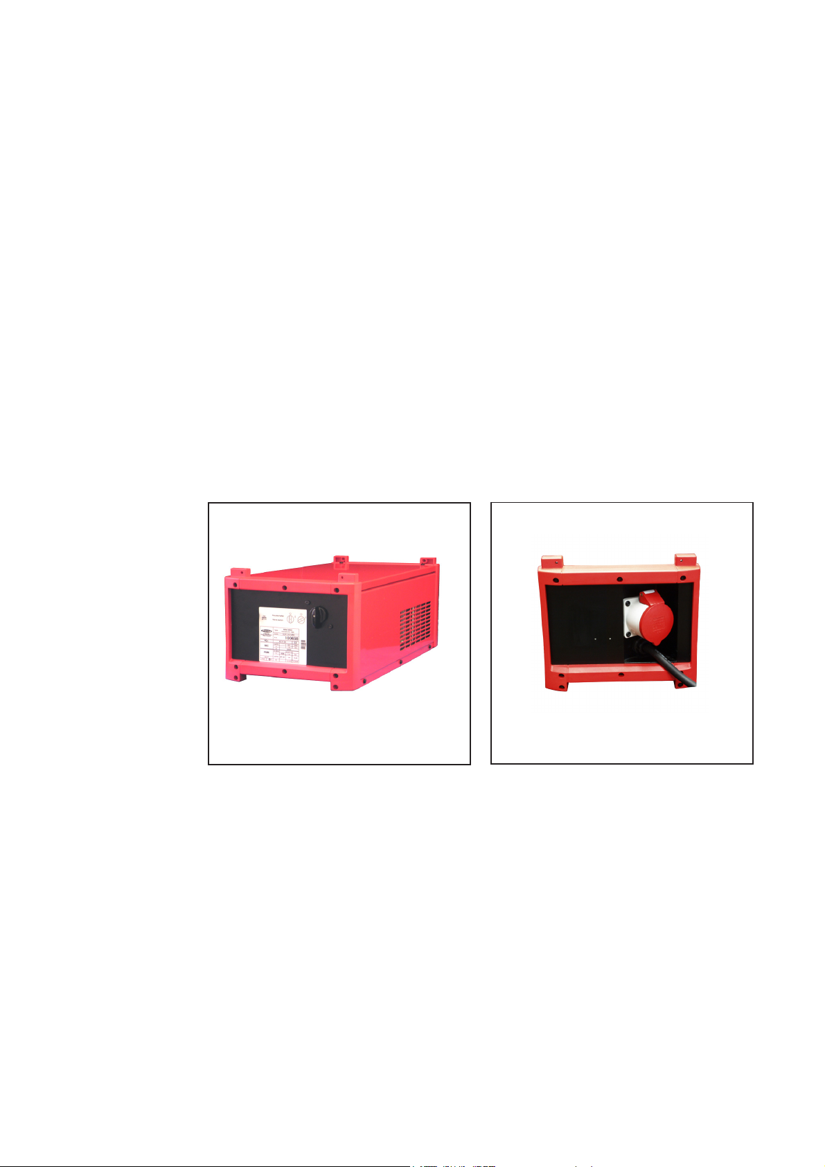
Fig. 1 Front view, „Version 1“
Fig. 2 Rear view, „Version 1“
2
Page 5

Versions
(continued)
Version 2:
- Auto-transformer MW 2600/3000 - 480/440 V
EN
Fig. 3 Front view, „Version 2“
Version 3:
- Auto-transformer MW 2600/3000 - 575 V
Fig. 5 Front view, „Version 3“
Fig. 4 Rear view, „Version 2“
Fig. 6 Rear view, „Version 3“
3
Page 6

Controls and connections
Controls and
connections
„Version 1“
(1)
(2)
(3)
Controls and
connections
„Version 2“
Fig. 1 Front view, auto-transformer TT 2600/3000
MW 2600/3000
Fig. 2 Rear view, auto-transformer TT 2600/3000
MW 2600/3000
(1) Main switch ... central switch for turning all system components of the welding
machine on and off
(2) Power source connection socket ... for supplying the power source with the
transformed voltage.
(3) Mains cable ... for supplying the auto-transformer with the mains voltage
(5)
(4)
(3)
(2)
Fig. 3 Front view. Auto-transformer MW2600
(1)
(6)
Fig. 4 Rear view. Auto-transformer MW2600
(1) Main switch ... central switch for turning all system components of the welding
machine on and off
(2) Socket fuse ...T10A 440V
(3) Power source connection cable „OUTPUT 50/60 Hz“ ... for supplying the power
source with the transformed voltage.
4
Page 7

Controls and
connections
„Version 2“
(continued)
Controls and
connections
„Version 3“
(4) Mains cable „INPUT 50/60Hz“ ... for supplying the auto-transformer with the mains
voltage
(5) Socket outlet ... 230V/10 A
(6) Strain relief devices ... for connection cables of external devices
EN
(2)
Fig. 5 Front view, auto-transformer MW2600 575 V
(1)
(5)
(6)
Fig. 6 Rear view, auto-transformer MW2600 575 V
(3)
(4)
(1) Main switch ... central switch for turning all system components of the welding
machine on and off
(2) Fan fuse ...T400mA 440 V
(3) Power source connection cable „OUTPUT 50/60 Hz“ ... for supplying the power
source with the transformed voltage.
(4) Mains cable „INPUT 50/60Hz“ ... for supplying the auto-transformer with the mains
voltage
(5) Blanking cover
(6) Blanking cover
5
Page 8

7
7
7
7
7
6
6
6
6
6
6
6
6
6
6
6
6
6
6
6
6
6
6
6
6
6
6
Setting the mains voltage
Safety
Converting the
mains voltage for
„Version 1“
WARNING! Work performed incorrectly can cause serious injury and damage.
The following activities must only be carried out by Fronius-trained qualified
personnel! Take note of the safety rules in the power source operating instructions.
WARNING! An electric shock can be fatal. Before opening the unit, turn the main
switch to the „0“ position and pull out the mains plug or disconnect the power
supply.
1. Turn the main switch on the auto-transformer to the „0“ position
2. Pull out the mains plug or disconnect the power supply
3. Remove the auto-transformer cover
Example: Converting from 500 V to 460 V
23456789012345
23456789012345
Setting
460 V
23456789012345
Setting
23456789012345
23456789012345
500 V
23456789012345
23456789012345
23456789012345
23456789012345
23456789012345
23456789012345
23456789012345
23456789012345
23456789012345
23456789012345
23456789012345
23456789012345
23456789012345
23456789012345
23456789012345
23456789012345
23456789012345
Mains cable (50/60Hz)
„INPUT 50/60 Hz“
234567890123456
460V
L3=W
460V
L2=V
234567890123456
460V
500V
234567890123456
234567890123456
234567890123456
L1=U
L3=W
500V
L2=V
500V
L1=U
460 /
500V
460 /
500V
460 /
500V
PE
Fig. 7 Terminal strip TT 2600/3000 MW 2600/3000 - 500/460 V
6
Page 9

Converting the
7
7
7
7
7
7
6
6
6
6
6
6
6
6
6
6
6
6
6
6
6
6
6
6
6
6
6
7
7
7
7
7
mains voltage for
„Version 1“
(continued)
Example: Converting from 480 V (230 V) to 440 V (200 V)
23456789012345
23456789012345
Setting
440 V
(200 V)
440V
440V
L3=W
200V
440V
L2=V
L1=U
200VL2200VL3230VL1230VL2230VL3200 /
L1
Setting
23456789012345
23456789012345
480 V
23456789012345
23456789012345
23456789012345
(230 V)
23456789012345
23456789012345
23456789012345
23456789012345
23456789012345
23456789012345
23456789012345
23456789012345
23456789012345
23456789012345
23456789012345
23456789012345
23456789012345
23456789012345
234567890123456
234567890123456
234567890123456
480V
480V
234567890123456
234567890123456
234567890123456
L3=W
L2=V
234567890123456
234567890123456
234567890123456
234567890123456
234567890123456
480V
L1=U
Mains cable (50/60Hz)
„INPUT 50/60 Hz“
440 /
440 /
440 /
480V
480V
480V
200 /
200 /
230V
230V
230V
PE
PE
EN
Fig. 8 Terminal strip TT 2600/3000 MW 2600/3000 - 480/440 V (TT 2600 MW 2600 - 230/200 V)
4. Disconnect the phase conductors (L1, L2, L3) in the „Setting 500 or 480 V (230 V)“
section
NOTE! Operating the auto-transformer with phase conductors only partially
reconnected can cause serious damage. When converting the mains voltage,
always make sure that all phase conductors are reconnected.
5. Connect the phase conductors (L1, L2, L3) in the „Setting 460 or 440 V (200 V)“
section
6. Check that all cables are securely connected to the terminal strip
7. Attach the auto-transformer cover
8. Cross out the mains voltage in the space above the rating plate and enter the mains
voltage you have set in the empty box
CAUTION! Operating the equipment at an incorrect mains voltage can cause
serious damage. The entered value must correspond to the mains voltage actually set.
Fig.9 Entering the mains voltage set - example
7
Page 10

Converting the
mains voltage for
„Version 2“
VOLTAGE CORRECTION DEVICE
480V 50/60Hz
CIRCUIT DIAGRAM
440/480V
INPUT 50/60 Hz
grey
U1
480V
grey
V1
480V
grey
W1
480V
440V
440V
440V
400V
OUTPUT 50/60 Hz
230V
230V~ 10A
KD 7000
PE
L1
L2
L3
L1
L2
L3
PE
0
PE
440V 50/60Hz
CIRCUIT DIAGRAM
grey
U1
grey
V1
grey
W1
KD 7000
Fig. 10 Connecting MW 2600 480/440 V
Fig. 11 Entering the mains voltage set
PE
L1
440/480V
L2
INPUT 50/60 Hz
L3
480V
480V
480V
440V
440V
440V
L1
L2
400V
L3
OUTPUT 50/60 Hz
PE
230V
0
230V~ 10A
PE
1. Turn the main switch on the autotransformer to the „0“ position
2. Pull out the mains plug or disconnect
the power supply
3. Remove the left side panel of the
auto-transformer
4. Disconnect the phase conductors
(U1, V1, W1) in the 480V section
NOTE! Operating the autotransformer with phase conductors only partially reconnected
can cause serious damage.
When converting the mains
voltage, always make sure that all
phase conductors are reconnected.
5. Connect the phase conductors (U1,
V1, W1) in the 440V section
6. Make sure all cables are securely
connected
7. Attach the left side panel of the autotransformer
8. Cross out the mains voltage in the
space above the rating plate and
enter the mains voltage you have set
in the empty box
CAUTION! Operating the equipment at an incorrect mains voltage can cause
serious damage. The entered value must correspond to the mains voltage actually set.
8
Page 11

Putting the machine into service
Safety
Preparing to
install
WARNING! Work performed incorrectly can cause serious injury and damage.
The following activities must only be carried out by Fronius-trained qualified
personnel! Take note of the safety rules in the power source operating instructions.
WARNING! An electric shock can be fatal. Only carry out work on the machine
when
- the mains switch is in the „0“ position,
- the machine is unplugged from the mains.
EN
Fig. 12 Dismantling the components
9
Page 12

Installing the
components
CAUTION! Beware of the danger of the trolley tipping over. Always place the
heavy auto-transformer at the bottom. This will reduce the danger of the trolley
tipping over as the centre of gravity is now lower.
Fig. 13 Installing the components
4 x
10
Page 13

Connecting the
auto-transformer
„Version 1“
WARNING! Operating the equipment incorrectly can cause serious injury and
damage. Read the following sections of the power source operating instructions
before starting the power source for the first time:
- Safety rules
- Putting the machine into service
- Putting the power source into operation
Connecting the
auto-transformer
„Versions 2 and
3“
The ventilation of the auto-transformer is a very important safety feature. When deciding
where to set up the system, ensure that cooling air can enter unhindered through the air
slots on the underside and escape through the slots in the sides.
1. If the auto-transformer mains cable needs to have a plug attached, fit a suitable
mains plug.
2. Switch the power source mains switch to the „0“ position
3. Turn the main switch on the auto-transformer to the „0“ position
4. Insert the mains plug of the auto-transformer and turn on the power supply.
5. Turn the main switch on the auto-transformer to the „I“ position
6. The auto-transformer is ready for use
Note: Operating the auto-transformer with phase conductors only partially
connected can cause serious damage. When connecting the connection cable,
always make sure that all phase conductors and the earth conductor are
connected.
WARNING! Operating the equipment incorrectly can cause serious injury and
damage. Read the following sections of the power source operating instructions
before starting the power source for the first time:
- Safety rules
- Putting the machine into service
- Putting the power source into operation
EN
The ventilation of the auto-transformer is a very important safety feature. When deciding
where to set up the system, ensure that cooling air can enter unhindered through the air
slots on the underside and escape through the slots in the sides.
1. If the auto-transformer mains cable „INPUT 50/60HZ“ needs to have a plug attached, fit a suitable mains plug.
2. Switch the power source mains switch to the „0“ position
3. Turn the main switch on the auto-transformer to the „0“ position
4. Connect the auto-transformer with power source to the terminals „OUTPUT 50/
60Hz“.
5. Insert the mains plug of the auto-transformer and turn on the power supply.
6. Turn the main switch on the auto-transformer to the „I“ position
7. The auto-transformer is ready for use
NOTE! Operating the auto-transformer with phase conductors only partially
connected can cause serious damage. When connecting the connection cable,
always make sure that all phase conductors and the earth conductor are
connected.
11
Page 14

Care, maintenance and disposal
General Under normal operating conditions the auto-transformer requires only a minimum of care
and maintenance. However, it is essential that certain important points are observed to
ensure the welding machine remains serviceable for many years to come.
WARNING! An electric shock can be fatal. Before opening the machine, turn off
the machine, disconnect the mains supply and attach a clearly legible and
comprehensible warning sign to prevent anyone switching it on again. Discharge electrolytic capacitors where necessary. The housing screws provide an
adequate PE conductor connection for earthing the housing. The screws must
never be replaced with different screws unless a reliable PE conductor connection is set up.
Every start-up
Every 6 months
Every 12 months
Disposal
- Check the mains plug and mains cable for damage
- Check that there is a gap of 0.5 m (1.6 ft.) all around the machine to ensure that
cooling air can flow and escape unhindered.
NOTE! Air inlets and outlets must never be covered, not even partially.
- Dismantle machine side panels and clean machine inside with dry reduced compressed air
NOTE! Risk of damage to electronic components. Do not bring the air nozzle
too close to the electronic components.
- If a lot of dust has accumulated, clean the cooling air ducts.
Carry out a safety inspection
(see the „Safety rules“ chapter in the power source operating instructions)
Dispose of in accordance with the applicable national and local regulations.
12
Page 15

Troubleshooting
General
Troubleshooting
WARNING! An electric shock can be fatal. Before opening the auto-transformer,
turn the mains switch to the „0“ position, pull out the mains plug and attach a
clearly legible and comprehensible warning sign to prevent anyone switching it on
again. The housing screws provide an adequate PE conductor connection for
earthing the housing. The screws must never be replaced with different screw
fastenings unless a reliable PE conductor connection is set up.
Power source does not function
Mains switch is on, but indicators are not lit up
Cause: There is a break in the mains lead; the mains plug is not plugged in
Remedy: Check mains lead, check mains voltage if necessary
Cause: Mains fuse is faulty
Remedy: Replace mains fuse
Cause: Mains outlet socket or plug is faulty
Remedy: Replace faulty components
Cause: Mains switch is faulty
Remedy: Replace the mains switch
EN
Cause: Phase conductors (L1, L2, L3) connected incorrectly
Remedy: Connect phase conductors as described
Mains fuse or automatic circuit breaker has tripped
Cause: Mains fuse underrated
Remedy: Rate mains lead fuse according to rating plate
Cause: Short circuit on the transformer windings
Remedy: Replace the auto-transformer
Output voltage too low on „Version 1“
Auto-transformer TT 2600/3000 MW 2600/3000 - 480/440V - 500/460 V
Cause: Incorrect mains voltage
Remedy: Check the mains voltage
Cause: Mains leads connected incorrectly
Remedy: Correct the mains connection
Cause: Mains voltage is 460 V or 440 V: Phase conductors (L1, L2, L3) connected
in the „500 V“ or „480 V“ sesction
Remedy: Connect phase conductors (L1, L2, L3) in the „460 V“ or „440 V“ section
Output voltage too high on „Version 1“
Auto-transformer TT 2600/3000 MW 2600/3000 - 480/440V - 500/460 V
Cause: Mains voltage is 500 V or 480 V: Phase conductors (L1, L2, L3) connected
in the „460 V“ or „440 V“ sesction
Remedy: Connect phase conductors (L1, L2, L3) in the „500 V“ or „480 V“ section
13
Page 16

Fault / Cause /
Remedy
(continued)
Output voltage too low on „Version 2“
Auto-transformer MW 2600 480/440V
Cause: Incorrect mains voltage
Remedy: Check the mains voltage
Cause: Mains leads connected incorrectly
Remedy: Correct the mains connection
Cause: Mains voltage is 440 V: Phase conductors (U1, V1, W1) connected in the
„480V“ section
Remedy: Connect phase conductors (U1, V1, W1) in the „440V“ section
Output voltage too high on „Version 2“
Auto-transformer MW 2600 480/440V
Cause: Mains voltage is 480 V: Phase conductors (U1, V1, W1) connected in the
„440V“ section
Remedy: Connect phase conductors (U1, V1, W1) in the „480V“ section
Surface of auto-transformer housing feels hot
Cause: Permitted duty cycle exceeded
Remedy: Move power source mains switch to „0“ position, allow auto-transformer to
cool
Important! The auto-transformer must remain switched on to allow the fan
to operate
Cause: The connected welding machine is drawing too much current
Remedy: Check the current consumption of the connected welding machine
Cause: Faulty fan fuse (only on MW 2600 - 575 V „Version 3“)
Remedy: Replace fuse
Cause: Fan faulty
Remedy: Check fan connections, replace fan
Cause: Unsuitable installation location
Remedy: Change installation location (ensure air can move freely through openings
in housing)
Cause: Ambient temperature too high
Remedy: Reduce ambient temperature or change installation location
Cause: Housing interior dirty
Remedy: Open auto-transformer and clean with dry compressed air
No voltage at the socket outlet („Version 2“ only)
Cause: Socket fuse faulty
Remedy: Replace fuse
14
Page 17

Technical data
Safety
Auto-transformer
„Version 1“ (480/
440 V, 500/460 V)
NOTE! Incorrectly rated mains plugs, mains leads or fuses can lead to serious
damage. If the power source is designed for a special voltage, the technical
data on the rating plate apply. The mains plug, mains lead and their fuse protection must be rated accordingly.
Auto-transformer 480/440 V
Auto-transformer 500/460 V
Mains voltage 1 3x480 V 3x500 V
Mains voltage 2 3x440 V 3x460 V
Mains voltage tolerance +/- 10 % +/- 10 %
Mains frequency 50/60 Hz 50/60 Hz
Output voltage 3x400 V 3x400 V
Mains fuse protection (slow-blow) 16 A 16 A
Maximum apparent power 12.1 kVA 12.1 kVA
Effective apparent power 10.4 kVA 10.4 kVA
Cos phi 0.9 0.9
Maximum primary current for
Mains voltage 1 14.5 A 14 A
Mains voltage 2 15.5 A 14 A
Effective primary current for
Mains voltage 1 12.5 A 12 A
Mains voltage 2 13.5 A 13 A
Secondary current for
10 min / 40 °C 65 % d.c. 17 A 17 A
10 min / 40 °C 100 % d.c. 14 A 14 A
Protection IP 23 IP 23
Type of cooling F F
Insulation class F F
Auto-transformer dimensions l/w/h
TT 2600/3000 630/240/250 mm 630/240/250 mm
24.80/9.45/9.84 in. 24.80/9.45/9.84 in.
Dimensions l/w/h
Auto-transformer MW 2600/3000 630/290/250 mm 630/290/250 mm
24.80/11.42/9.84 in. 24.80/11.42/9.84 in.
Weight 39.5 kg 39.5 kg
87.1 lb. 87.1 lb.
Marks of conformity CE, CSA CE, CSA
EN
15
Page 18

Auto-transformer
„Version 1“ (230/
200 V)
Auto-transformer 230/200 V
Mains voltage 1 3x230 V
Mains voltage 2 3x200 V
Mains voltage tolerance +/- 10 %
Mains frequency 50/60 Hz
Output voltage 3x400 V
Mains fuse protection (slow-blow) 35 A
Maximum apparent power 11.8 kVA
Effective apparent power 9.7 kVA
Cos phi 0.9
Maximum primary current for
Mains voltage 1 34 A
Mains voltage 2 30 A
Effective primary current for
Mains voltage 1 28 A
Mains voltage 2 25 A
Secondary current for
10 min / 40 °C 65 % d.c. 17 A
10 min / 40 °C 100 % d.c. 14 A
Protection IP 23
Type of cooling F
Insulation class F
Auto-transformer dimensions l/w/hTT 2600/3000 630/240/250 mm
24.80/9.45/9.84 in.
Dimensions l/w/hAuto-transformer MW 2600/3000 630/290/250 mm
24.80/11.42/9.84 in.
Weight 45 kg
99.20 lb.
Marks of conformity CE
16
Page 19

Auto-transformer
„Versions 2 and
3“
Auto-transformer 480/440 V
Auto-transformer 575 V
Mains voltage 1 3x480 V 3x575 V
Mains voltage 2 3x440 V -
Mains voltage tolerance +/- 10 % +/- 10 %
Mains frequency 50/60 Hz 50/60 Hz
Output voltage 3x400 V 3x400 V
Mains fuse protection (slow-blow) 16 A 16 A
Fan fuse (slow-blow) 0.4 A
230 V fuse (slow-blow) 10 A -
Maximum apparent power 12.1 kVA 12.1 kVA
Effective apparent power 10.4 kVA 10.4 kVA
Cos phi 0.9 0.9
Maximum primary current for
Mains voltage 1 14.5 A 12 A
Mains voltage 2 15.5 A
Effective primary current for
Mains voltage 1 12.5 A 10.4 A
Mains voltage 2 13.5 A
Secondary current for
10 min / 40 °C 65 % d.c. 17 A 17 A
10 min / 40 °C 100 % d.c. 14 A 14 A
Protection IP 23 IP 23
Type of cooling F F
Insulation class F F
Dimensions l/w/h 630/290/250 mm 630/290/250 mm
24.80/11.42/9.84 in. 24.80/11.42/9.84 in.
Weight 39 kg 39.5 kg
86 lb. 87.1 lb.
Marks of conformity CE, CSA CE, CSA
EN
17
Page 20

18
Page 21

Ersatzteilliste
DEENFRITESPT-BRNLNOCSRUSKSVTR
Schaltplan
Spare Parts List
Circuit Diagram
Liste de pièces de rechange
Schéma de connexions
Lista parti di ricambio
Schema
Lista de repuestos
Esquema de cableado
Lista de peças sobresselentes
Esquema de conexões
Onderdelenlijst
Bedradingsschema
Reservdelsliste
Koblingsplan
Seznam náhradních dílù
Schéma zapojení
Список запасных частей
Электрическая схема
Zoznam náhradných dielov
Schéma zapojenia
Reservdelslistan
Kopplingsschema
ud_fr_st_tb_00149 012012
Parça Listesi
Baðlantý þemasý
Czyszczenie palnika
PL
Schemat po³¹czeñ
Page 22

Auto Transformer MW 2600 480;440V/400V 4,001,568,800
Auto Transformer MW 2600 3x575V/400V 4,001,631,800
AM2,0200,8927
AM2,0200,8827
AM2,0200,8823
33,0030,0094 - 3x480;440V
33,0030,0096 - 3x575V/400V
41,0007,0169
41,0007,0158
41,0007,0166 - 10A/500V
41,0007,0179 - 0,4A/440V
41,0007,0159
41,0009,0197 - 10²
41,0009,0198 - 10²
41,0009,0217 - 0,2-4²
41,0009,0216 - 0,2-4²
43,0006,0042
43,0004,2567
43,0004,2323
42,0201,0256
42,0300,1815 - PG16
42,0300,0648 - PG13,5
43,0003,0316
43,0003,0315
22,0405,0163
BE2,0201,1678
22,0405,0163
43,0002,0257
42,0406,0137
Auto - Transformer MW 2600
Ersatzteilliste / Spare parts list / Listes de pièces de rechange / Lista de repuestos / Lista de pecas sobresselentes / Lista dei Ricambi
el_fr_st_so_00878 012004
1/1
Page 23

Auto Transformer 3x480; 440/400V TT 2600 4,001,614
Auto Transformer 3x500; 460/400V TT 2600 4,001,615
AM2,0200,9036
AM2,0200,8827
AM2,0200,8823
33,0030,0047
43,0006,0042
43,0004,0507
43,0003,0317
42,0300,1511
22,0405,0166
41,0009,0066
BE4,0450,1018
22,0405,0166
43,0002,0257
42,0406,0137
Auto - Transformer TT2600
Ersatzteilliste / Spare parts list / Listes de pièces de rechange / Lista de repuestos / Lista de pecas sobresselentes / Lista dei Ricambi
1/1
el_fr_st_so_01103 012005
Page 24

TT 2600/3000- MW 2600/3000 - 440/480 V („Ausführung 1“)
Page 25

TT 2600/3000- MW 2600/3000 - 460/500 V („Ausführung 1“)
Page 26

MW 2600 / TT 2600 - 230/200 V („Ausführung 1“)
Page 27

MW 2600 - 440/480 V („Ausführung 2“)
Page 28

FRONIUS INTERNATIONAL GMBH
Froniusplatz 1, A-4600 Wels, Austria
Tel: +43 (0)7242 241-0, Fax: +43 (0)7242 241-3940
E-Mail: sales@fronius.com
www.fronius.com
Under http://www.fronius.com/addresses you will find all addresses
www.fronius.com/addresses
of our Sales & service partners and Locations.
ud_fr_st_so_00082 012011
 Loading...