

Page 1

User
Information
Australian edition - control panel
User Information
EN
42,0426,0003,EN 002-23092022
Page 2

Page 3
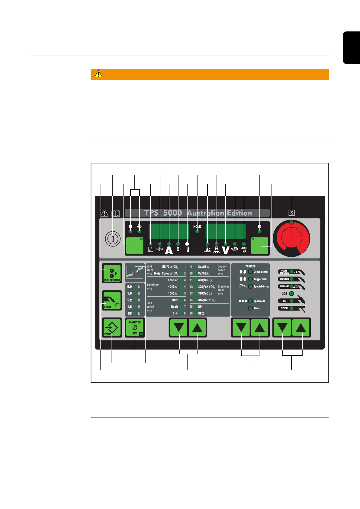
“Australian Edition” control panel
(1)
(24)
(23)
(19)
(18)
(16)
(15)
(14)
(13)
(12)(11)
(9) )3()8(
(2)
(19)
(22)
(21) (20)
(7)
(6)
(5)
(4)
(10)
(17)
EN
Safety
“Australian Edition” control
panel
WARNING!
Danger from incorrect operation and work that is not carried out properly.
This can result in serious personal injury and damage to property.
All the work and functions described in this document must only be carried
▶
out by technically trained and qualified personnel.
Read and understand this document in full.
▶
Read and understand all safety rules and user documentation for this device
▶
and all system components.
(1) Adjusting dial
for altering parameters. If the indicator on the adjusting dial is lit up,
then the selected parameter is one that can be altered.
3
Page 4

(2) Parameter selection button
for selecting the following parameters:
“a”-dimension
sheet thickness
welding current
F1 indicator
Wire-feed rate drive current-input indicator
If the indicators are lit up on the parameter selection button and on the
adjusting dial, then the indicated/selected parameter can be altered
with the adjusting dial.
(3) Parameter selection button
for selecting the following parameters:
arc length correction
droplet detachment /arc force dynamic correction
welding voltage
welding speed
o
Job N
F3 indicator
If the indicators are lit up on the parameter selection button and on the
adjusting dial, then the indicated/selected parameter can be altered
with the adjusting dial.
(4) Process button(s)
for selecting the welding process
MIG/MAG pulse synergic welding
MIG/MAG standard synergic welding
MIG/MAG standard manual welding
Job mode
TIG welding with touchdown ignition
Rod electrode (MMA) welding
(5) Mode button(s)
for selecting the operating mode
2-step mode (conventional)
4-step mode (trigger Lock)
Special 4-step mode (Aluminium welding start-up)
Spot welding mode
Operating Mode
(6) Material button(s)
for selecting the filler metal and shielding gas to be used. Parameters
SP1 and SP2 are reserved for additional materials.
4
Page 5

(7) Wire diameter button
for selecting the diameter of the wire to be used. Parameter SP is reserved for additional wire diameters.
(8) Welding current parameter
for selecting the welding amperage. Before the start of welding, the machine automatically displays a guideline value based on the programmed
parameters. During welding, the actual value is displayed.
(9) Welding voltage parameter
for selecting the welding voltage. Before the start of welding, the machine automatically displays a guideline value based on the programmed
parameters. During welding, the actual value is displayed.
Important! The power source has a pulsating open-circuit voltage.
Where the “Rod electrode (MMA) welding” process has been selected,
the display indicates an average welding-voltage value of 40 V before
the start of welding (open circuit).
For welding start-up and the main welding operation itself, however, a
welding voltage of max. 50 V (TPS 2700) or 70 V (TS/TPS 4000/5000)
is available. Optimum ignition properties are ensured.
(10) “a”-dimension parameter
for selecting the “a” dimension. The wirespeed and welding current /
voltage are calculated as a function of the pre-set welding speed.
EN
Important! Before you select the “a”-dimension, the welding-speed
parameter (17) must be set (recommended welding speed for manual
welding: ~35 cm/min or 13.78 ipm)
(11) Sheet thickness parameter
for selecting the sheet thickness in mm or in. This automatically sets all
the other parameters as well.
(12) Wirespeed parameter
for selecting the wirespeed in m/min or ipm. Other parameters that are
dependent on this are also automatically adjusted accordingly.
(13) Overtemperature indicator
lights up if the power source overheats (e.g. because the duty cycle has
been exceeded). For more information on this, see the “Troubleshooting” section.
(14) HOLD indicator
every time you finish a welding operation, the actual values for welding
current and voltage are stored, and the “Hold” indicator lights up.
(15) Arc length correction parameter
for correcting the arc length
- shorter arc length
0 neutral arc length
+ longer arc length
5
Page 6

(16) Droplet detachment, arc-force correction and arc-force parameter
has a different function assigned to it, depending on the process being
used.
MIG/MAG standard-synergic welding ... for influencing the short-circuiting dynamic at the instant of droplet transfer
- harder and more stable arc
0 neutral arc
+ soft and low-spatter arc
MIG/MAG pulse-synergic welding ... continuous correction facility for
the droplet-detachment force
- lower droplet-detachment force
0 neutral droplet-detachment force
+ increased droplet-detachment force
MIG/MAG standard manual welding ... for influencing the short-circuiting dynamic at the instant of droplet transfer
0 harder and more stable arc
10 soft, low-spatter arc
Rod electrode (MMA) welding ... for influencing the short-circuiting amperage at the instant of droplet transfer
0 soft, low-spatter arc
100 harder, more stable arc
(17) Welding-speed parameter
for selecting the welding speed. The wirespeed and welding current &
voltage are calculated as a function of the “a”-dimension parameter
(10).
(18) JOB n° parameter
for retrieving parameter records / job numbers that were previously
saved with the “Store” button
(19) Indicators F1 / wirefeed-drive current input / F3
for displaying defined parameters
(20) Intermediate arc indicator
between the dip-transfer arc and the spray arc, a spatter-prone “intermediate arc” occurs. To alert you to this critical area - and help you
avoid it - the intermediate arc indicator lights up.
(21) Store button
for accessing the Set-up menu or (in Job Mode) for storing parameter
settings.
Important! If you press the Store button (21) and the “Material” button
(6) at the same time, the display gives you a read-out of the software
version.
If you then press the “Material” button (6) on its own, the version number of the welding databank appears on the display (e.g.: “0 | 029” =
M0029).
If you then press the “Material” button (6) a second time, the number of
the wirefeeder (A, or B in the case of twin-head mounts) and the software version n° of the wirefeeder appear on the display (e.g.: A 1.5 |
0.23).
To exit, press the Store button (21).
6
Page 7

(22) Gas test button
for setting the required gas-flow rate on the pressure regulator. After
you press this button, gas will flow out for 30 s. Press the button again
to stop the gas test-flow before the end of this period.
If you press the Store button (21) and the gas-test button (22) at the
same time, the display gives you a read-out of the pre-set gas pre-flow
time (e.g. “GPr | 0.1 s”).
- You can alter the gas pre-flow time with the adjusting dial (1)
If you now press the “Process” button (4), the display gives you a readout of the pre-set gas post-flow time (e.g. “GPo | 0.5 s”)
- You can alter the gas post-flow time with the adjusting dial (1)
To exit, press the Store button (21).
(23) "Feeder inching" button
for feeding the welding wire into the torch hosepack with no accompanying flow of gas or current
For information on the various wire-inching sequences that are possible
when the welder presses and holds the “"Feeder inching" button”, see
the section headed “The Set-up Menu“, sub-section “’Process’ parameters”, parameter “Fdi“.
EN
Important! If you press the Store button (21) and the "Feeder inching"
button (23) at the same time, the display gives you a read-out of the
pre-set feeder-inching speed (e.g. “Fdi | 10 m/min” or 393.70 ipm).
- You can alter the feeder-inching speed with the adjusting dial (1)
To exit, press the Store button (21).
(24) Keylock switch (Option)
When the key is in the horizontal position, the following functions are
disabled:
Selecting the welding process with the “Process” button(s) (4)
-
Selecting the operating mode with the “Mode” button(s) (5)
-
Selecting the filler metal with the “Material” button(s) (6)
-
Accessing the set-up menu with the “Store” button (21)
-
Accessing the job-correction menu (see the section headed “Job
-
mode”)
Important! In this case, the functions available on the control panel of the system components are then restricted in the same way
as those of the control panel on the power source.
7
Page 8

 Loading...