

Page 1

/ Perfect Welding / Solar Energy / Perfect Charging
Translation of original Operating
Instructions
ArcRover 15
Operating Instructions
EN
Welding carriage
42,0426,0298,EN 19112019
Page 2

Page 3

Contents
About this document ........................................................................................................................................ 5
Function of this document .......................................................................................................................... 5
Explanation of safety notices ..................................................................................................................... 5
Copyright .................................................................................................................................................... 5
Qualied personnel .................................................................................................................................... 5
General ............................................................................................................................................................ 6
Principle......................................................................................................................................................6
Device concept ........................................................................................................................................... 6
Application area ......................................................................................................................................... 6
Proper use/intended purpose ..................................................................................................................... 6
Foreseeable misuse ................................................................................................................................... 7
Conversions or modications ..................................................................................................................... 7
Operating Instructions ................................................................................................................................ 7
Duty to provide instruction .......................................................................................................................... 7
Dangers from the rechargeable battery pack ............................................................................................. 8
Use of charger and rechargeable battery pack .......................................................................................... 9
Environmental conditions ........................................................................................................................... 9
Warning notices on the carriage ...............................................................................................................10
Scope of supply ........................................................................................................................................ 11
Carriage components .................................................................................................................................... 12
ArcRover 15 carriage ............................................................................................................................... 12
Accessories and options ............................................................................................................................... 13
Accessories .............................................................................................................................................. 13
Control and display elements, connections ................................................................................................... 15
Carriage....................................................................................................................................................15
Control panel ............................................................................................................................................ 16
Display types ............................................................................................................................................ 17
Parameter description .............................................................................................................................. 18
Charger and rechargeable battery pack ................................................................................................... 19
Menu navigation and parameter entry ........................................................................................................... 20
General.....................................................................................................................................................20
Turning/pressing the adjusting dial ...........................................................................................................20
Welding position and weld seam tracking .....................................................................................................21
Possible welding positions ....................................................................................................................... 21
Guidance of the carriage .......................................................................................................................... 22
Optional lateral guides ............................................................................................................................. 24
Preparing the carriage ................................................................................................................................... 25
Mounting and setting up the guide rails ................................................................................................... 25
Fitting the carriage brushes (option) ........................................................................................................ 26
Fitting the lateral guides (option) .............................................................................................................. 27
Fitting lateral guides with guide rails ........................................................................................................ 28
Charging the rechargeable battery pack .................................................................................................. 29
Insert rechargeable battery pack into the carriage ................................................................................... 30
Connecting the external power supply (option) ........................................................................................ 31
Setting up the carriage .................................................................................................................................. 32
Checking the surface of the workpiece and the carriage to ensure they are clean .................................. 32
Placing the carriage ................................................................................................................................. 32
Attaching fall protection (vertical operation) ............................................................................................. 33
Mounting and adjusting the welding torch ................................................................................................ 34
Relieving strain on the carriage ................................................................................................................ 35
Starting up the carriage ................................................................................................................................. 36
Checking the connections ........................................................................................................................ 36
Switching on the system components ...................................................................................................... 36
Retrieving parameter record (JOB) on the power source ........................................................................ 36
Page 4

Setting the carriage parameters .................................................................................................................... 37
Setting the unit ......................................................................................................................................... 37
Creating the carriage program ................................................................................................................. 38
Welding mode ...............................................................................................................................................39
Performing a test run ............................................................................................................................... 39
Starting the welding process .................................................................................................................... 39
End of welding .......................................................................................................................................... 39
Troubleshooting ............................................................................................................................................. 40
General.....................................................................................................................................................40
Displayed error messages ....................................................................................................................... 40
Carriage....................................................................................................................................................40
Maintenance .................................................................................................................................................. 42
Personnel ................................................................................................................................................. 42
Maintenance record ................................................................................................................................. 42
Cleaning ................................................................................................................................................... 42
Maintenance intervals .............................................................................................................................. 42
Recommended lubricants ........................................................................................................................ 42
Horizontal welding torch adjustment unit ................................................................................................. 43
Vertical welding torch adjustment unit ...................................................................................................... 44
Carriage front ........................................................................................................................................... 45
Carriage back ........................................................................................................................................... 45
Charger .................................................................................................................................................... 46
Rechargeable battery pack ...................................................................................................................... 46
Disposal of components ........................................................................................................................... 47
Technical Data ............................................................................................................................................... 48
ArcRover 15 carriage ............................................................................................................................... 48
ArcRover 15 dimensions .......................................................................................................................... 49
Environmental conditions ......................................................................................................................... 49
Spare parts .................................................................................................................................................... 50
Spare parts, wearing parts and auxiliary materials .................................................................................. 50
Details required when placing orders ....................................................................................................... 50
„External power supply“ option ................................................................................................................. 53
Circuit Diagrams ............................................................................................................................................ 54
EU Declaration of Conformity ........................................................................................................................ 58
Page 5

About this document
Function of this
document
Explanation of
safety notices
These Operating Instructions explain how to commission and operate the carriage. Look
after the Operating Instructions carefully; they must always be to hand at the location
where the carriage is being used. They can be used as a reference should any operational or functional problems occur in the future.
DANGER!
Indicates an imminent danger. If not avoided, death or serious injury will result.
WARNING!
Indicates a possibly dangerous situation. If not avoided, death or serious injury may
result.
CAUTION!
Indicates a possibly harmful situation. If not avoided, minor or minor injury may result.
NOTE!
Indicates a risk of awed results and possible damage to the equipment.
IMPORTANT! Indicates usage tips and other particularly useful information. It is not a
signal word for a harmful or dangerous situation.
Copyright
Qualied
personnel
Special care is required if you see any of the symbols shown.
Copyright of these Operating Instructions remains with Fronius International GmbH. The
text and illustrations are all technically correct at the time of going to press. We reserve
the right to make changes. The content of the Operating Instructions shall not give rise to
any claims whatsoever on the part of the purchaser.
- These Operating Instructions are designed for trained personnel or persons with
practical welding experience. Personnel must be trained through veriable regular
instruction.
- Maintenance and repair of the carriage may likewise only be carried out by trained
technicians and in compliance with the specied maintenance activities and maintenance intervals.
- The manufacturer accepts no liability for damage caused by insucient knowledge of
how to use the device.
5
Page 6

General
Principle The ArcRover 15 carriage is a portable, battery-powered welding carriage with 4-wheel
drive. The carriage is used to execute mechanised butt and llet welds in horizontal or
vertical welding positions.
Device concept
The ArcRover 15 carriage has been
designed for exibility and to improve
productivity in the execution of longitudinal
weld seams. A spatter guard mounted on
the working side and powder coating of all
housing components enable use in harsh
operating conditions.
A large holding and carrying handle coupled with a robust yet lightweight design
allows quick and easy positioning on the
workpiece.
The carriage adheres to the workpiece
by means of a permanent magnet. This
guarantees the best possible traction even
in vertical use.
Adjustable guide rollers on the side of the
carriage ensure optimal tracking of the
weld seam.
ArcRover 15 carriage
The carriage is powered by the interchangeable rechargeable battery pack.
The control unit is integrated into the carriage. The control panel has an illuminated display allowing simple and user-friendly parameter setting for the carriage.
The universal torch holder allows use of
both manual and machine welding torches.
Application area The ArcRover 15 carriage can be used in all situations where a high degree of exibility
is required when executing longitudinal weld seams:
- Shipyards
- Bridge construction
- Workshops
- Production halls
- Building sites
Proper use/
intended purpose
The ArcRover 15 carriage must only be used for performing mechanised butt and llet
welds in horizontal or vertical welding positions. Any other use shall be deemed improper
and the manufacturer will assume no responsibility for any resulting damages.
The carriage can be used in the following welding processes:
- MIG / MAG process
Proper use also includes:
- Use of the charger and rechargeable battery pack included with the carriage
- Use of the permanent magnet with a minimum sheet thickness of 5 mm
- Use of MIG/MAG welding torches with a holder diameter of up to 28 mm
- Use in welding position PA with the “stainless steel drive wheel” option
- Carrying out all maintenance work at the specied maintenance intervals
- Keeping a service book with the most important information (date, operator, activities
carried out)
6
Page 7

Proper use/
intended purpose
(continued)
- Using the spare parts stipulated by Fronius
- Following all the instructions contained in the Operating Instructions
- Using this document in combination with the operating instructions for the integrated
system components (power source, wirefeeder, etc.)
Foreseeable
misuse
Conversions or
modications
Operating
Instructions
Any use other than for the intended purpose shall be deemed improper use. This includes:
- Operation on preheated components > 50 °C without stainless steel drive wheels
- Transporting people
- Use outside the permitted technical operating limits
- Use in hazardous areas
Any unauthorised conversions or modications made to the carriage by the user shall
invalidate all liability or warranty obligations on the part of the manufacturer!
The electromagnetic characteristics of the carriage can be adversely aected by additions or modications of any kind. No modications or additions should therefore be
undertaken without rst consulting the manufacturer and obtaining written approval.
The Operating Instructions help you to use the carriage safely and eciently, and must
therefore be to hand at all times:
- The Operating Instructions must always be kept near the carriage.
- Clearly mark the place where the instructions are kept.
- Ensure that all persons using the carriage know where the Operating Instructions are
located.
- The Operating Instructions will only be able to help you in the event of a problem if
they are at hand!
Duty to provide
instruction
IMPORTANT! The manufacturer shall not be liable for any damage that arises from fail-
ure to observe the Operating Instructions!
The operator must inform all people working with the carriage about the following before
starting work:
- Theoretical and practical aspects of operation
- Safety regulations
IMPORTANT! The duty to provide instruction applies in particular for people who only
work on the carriage occasionally.
7
Page 8
Dangers from
the rechargeable
battery pack
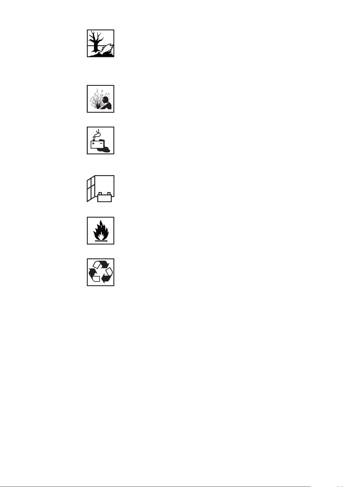
The substances contained in the battery used in this device can be harmful
to the environment and to human and animal health. If the device becomes
damaged, please observe the following points:
- Make sure that leaking uids cannot get into the soil or groundwater
- If pollution has already occurred, it must be removed in accordance with
relevant national regulations
The battery can catch re if overheated. Do not expose the device to heat
(e.g. a permanent heat source or re).
If the battery is damaged or subjected to improper use, dangerous vapours
may be given o which can irritate the airways.
Measures:
- Ensure an adequate supply of fresh air
- Seek medical attention in case of discomfort
With a faulty battery, liquid may leak out of the device.
- Avoid contact with the liquid
- Hand the device over to a Fronius Service Partner for repair
- Clean and check any parts that have come into contact with the liquid
Do not operate or store the device in a potentially explosive atmosphere.
Special regulations apply in rooms at risk of re or explosion:
- Observe relevant national and international regulations
To comply with European Directive 2006/66/EC on batteries and accumulators and its implementation in national law, batteries and rechargeable
batteries that have reached the end of their life must be collected separately
and returned to an approved recycling facility.
- Be sure to return any device that you no longer require to your dealer, or
nd out about the approved collection and recycling facilities in your area.
Ignoring this European Directive may be harmful to the environment and
your own health!
Devices with mechanically undamaged rechargeable batteries may be
returned to the relevant Fronius Service Partner for repair or battery replacement.
As soon as it becomes evident that the rechargeable battery has been mechanically damaged (e.g. electrolyte is escaping), dispose of the device at
your nearest recycling centre in accordance with national laws and guidelines.
If anything is unclear or you have any questions about disposal, contact your
Fronius Service Partner.
8
Page 9

Use of
charger and
rechargeable
battery pack
- The charger and the rechargeable battery pack are designed for each other. Therefore
you should only ever use the supplied charger to charge the battery pack.
- Recharge the rechargeable battery pack after every discharge. Do not wait until the
rechargeable battery pack is completely discharged before recharging it.
- Objects must not be passed through the ventilation openings of the charger.
- Charging/discharging of the battery must be carried out according to the relevant
requirements for the environmental conditions (technical data).
- Should unusual temperatures, odours, discolorations or deformations occur during the
charging process, halt the process immediately.
- Disconnect the charger from the mains and rechargeable battery pack when not in
use.
- When handling the battery, check the packaging and/or the battery itself for obvious
signs of damage.
- Do not open, crush, dismantle or drop the rechargeable battery pack from a large
height.
- Do not short-circuit the rechargeable battery pack or expose it to high temperatures.
- Keep the rechargeable battery pack away from direct sunlight and other heat sources.
- Do not place the rechargeable battery pack or the charger on moist or wet surfaces.
- Do not operate the rechargeable battery pack and charger in environments where they
are exposed to dust, ammable gases, steam or solvents. Do not use in environments
with strong vibrations and magnetic elds.
Environmental
conditions
Operating, storing or transporting the system outside the specied area or environmental ranges is regarded as not complying with the intended purpose. The manufacturer
shall not be liable for any damage or loss resulting from this.
Ambient air temperature range:
- during operation: 0 °C to +40 °C (32 °F to 104 °F)
- during transport and storage: -10 °C to+45 °C (14 °F to 113 °F)
- Recommended temperature range during charging: +5 °C to +40 °C (41 °F to
104 °F)
Relative humidity:
- up to 65% +/- 20%
Environmental conditions:
- Surrounding air is free from dust and ammable vapours, solvents or gases.
- No strong vibrations and magnetic elds around the rechargeable battery pack.
- No direct sunlight on the rechargeable battery pack.
- No storing the rechargeable battery pack on moist or wet surfaces.
9
Page 10
Warning notices
Type:
Ser.No.:
Art.No.:
U weight
max. load
25,4 VDC 7,1 kg
15 kg
11 kg
www.fronius.com
Froniusstraße 1
Pettenbach 4643
ArcRover 15
8,045,645
XXXXXXXX
on the carriage
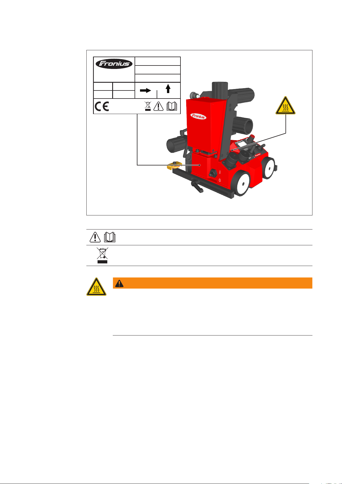
A number of safety symbols can be seen on the rating plate axed to the carriage. The
rating plate and safety symbols must not be removed or painted over.
ArcRover 15 rating plate
Do not use the functions until you have fully read the Operating Instructions.
Do not dispose of used devices with domestic waste. Dispose of them according to safety rules.
WARNING!
Risk of burns from hot surfaces.
The protective plate for the wheels heats up during long periods of welding
operation. Touching the plate may cause burns.
- Do not touch the protective plate.
- Wear protective gloves and suitable safety goggles or a protective hel-
met.
10
Page 11
Scope of supply
(2)(1) (3)
(4)
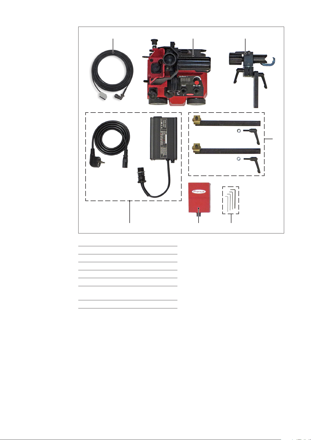
ArcRover 15 scope of supply
(1) Connecting cable to power source
(2) ArcRover 15 carriage
(3) Universal welding torch holder
(4) Guide rails
(5) Allen keys: 2 / 2.5 / 3 / 4
(6) Rechargeable battery pack
25.4 V / 3.35 Ah
(7) Charger
(6)(7) (5)
11
Page 12

Carriage components
ArcRover 15
carriage
Rechargeable
battery pack
25.4 V / 3.35 Ah
Horizontal
welding torch
adjustment unit
Vertical welding
torch adjustment
unit
Handle
Universal
welding torch
holder
Lashing point
for securing the
carriage
On-board
control unit
Chassis with
4-wheel drive
ArcRover 15 carriage
Guide rails
with rollers
12
Page 13

Accessories and options
Accessories
Article: Item number: Designation:
48,0005,2589 Stainless steel drive wheel
(for workpieces with particularly rough surfaces).
IMPORTANT! Use of the carriage with the "stainless steel drive wheel" accessory is
only permitted in the PA welding position. Please seek advice with Fronius service personnel if using pre-heated workpieces.
48,0005,2588 Brushes (2 pcs)
48,0005,2600 Rechargeable battery pack
25.4 V / 6.8 Ah
48,0005,2601 Charger
100-240 V 50/60 Hz /
29.4 V DC
48,0005,0165 External power supply
230V AC / 24V DC
38,0100,0433 Remote control cable 10 m
38,0100,0476 Extension cable 10 m
4,100,711 I-set external start signal
VR5000
(necessary for use with TransSteel;
installed in the wirefeeder)
13
Page 14

Accessories
(continued)
Article: Item number: Designation:
4,100,779,IK OPT/i WF external start
signal
(necessary in combination
with TPSi; installed in the WF
wirefeeder)
48,0005,2585 Tiltable lateral guide
48,0005,2584 Lateral guide for edge
(2)
(3)(1)
48,0005,2586 Magnetic lateral guide
(1) 48,0005,2587 Guide arm for rail 1850 mm
(2 pcs)
(2) 48,0005,1894 Flexible guide rail 1850 mm
(3) 48,0005,1895 Magnetic guide rail base
14
Page 15
Control and display elements, connections
Carriage
WARNING!
Operating the equipment incorrectly can cause serious injury and damage.
Do not use the functions described here until you have fully read and understood the
following documents:
- These Operating Instructions
- All operating instructions for the system components
(7)
(6)
(5)
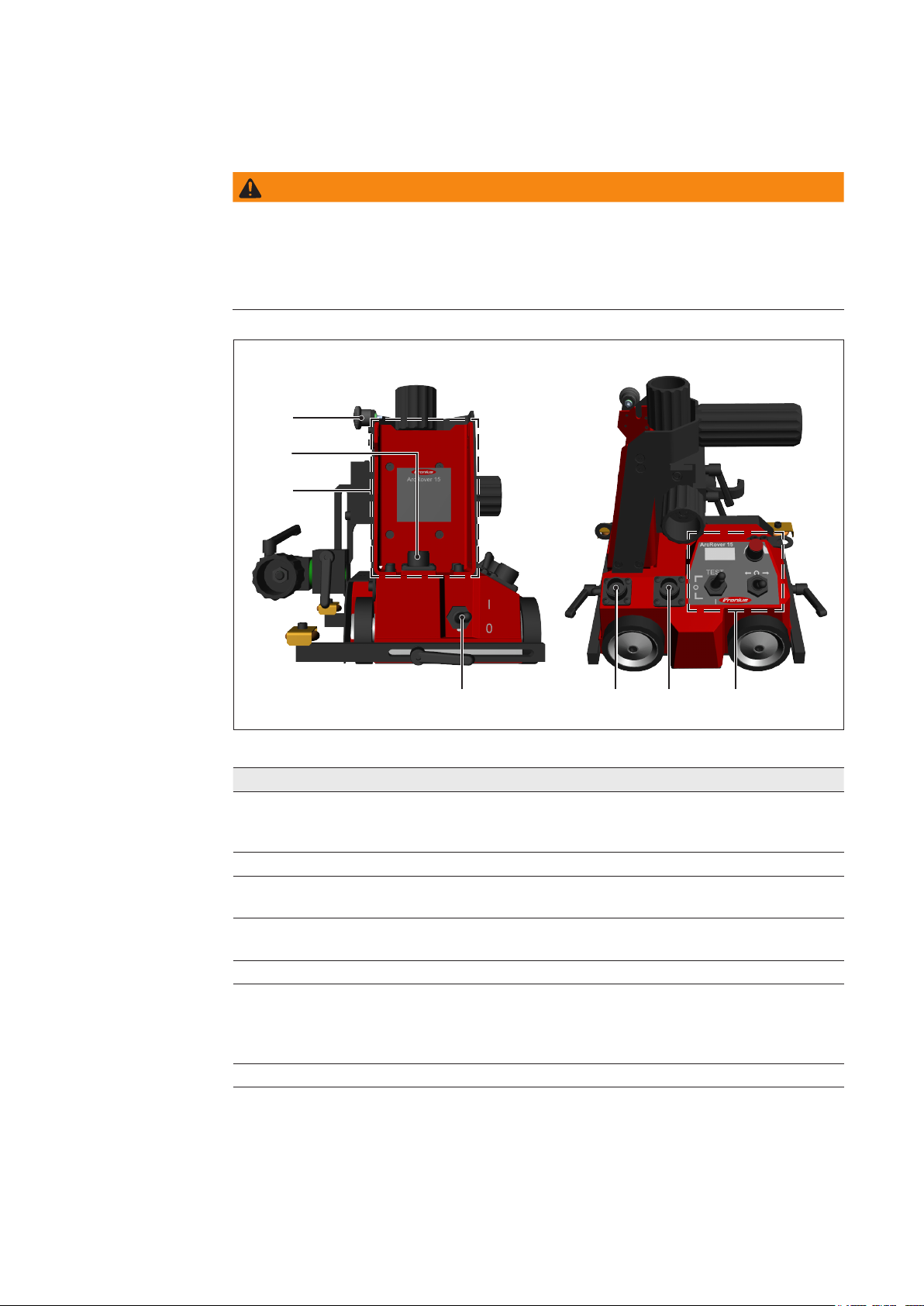
ArcRover 15 carriage
No. Function
(1) Control panel
- For the complete operation of the carriage.
- For conguring carriage parameters and creating programs.
(2) Connecting plug for diagnostic and service purposes
(3) Connecting plug for power source control
For connecting the cable to the power source.
(4) Control unit ON/OFF toggle switch
For switching the carriage control unit on and o.
(5) Compartment for rechargeable battery pack
(6) Connecting plug for rechargeable battery pack
- for plugging in the rechargeable battery pack (Li-Ion 25.4V / 3.35Ah)
- for connecting the connection cable of the control box during mains operation
(external power supply)
(7) Lock knob for locking the battery
(2) (1)(3)(4)
15
Page 16

Control panel
(1)
(2)
TEST
O
O
I
(4)
ArcRover 15 control panel
No. Function
(1) Display
For conguring parameters and creating programs using the menu adjusting dial
(2). The digital display is illuminated.
(2) Adjusting dial menu
- Used to adjust the Travel Speed of the carriage. The currently set speed is
shown on the display.
Setting range: 5 - 250 cm/min
- For menu navigation and parameter entry.
(3) Toggle switch Start LEFT/0/RIGHT
For starting and stopping the automatic program sequence in the relevant welding direction.
(4) Toggle switch/button Welding I/0/TEST
For choosing whether to carry out the automatic program sequence with or without welding.
I ... Welding on preselection
0 ... Welding o preselection
TEST ... Arc immediately active (arc test)
(3)
16
Page 17

Display types
Display Description
Display test (after switching on).
Carriage programs: 0 - 9
Status of the currently set Travel Speed in cm/min.
Speed (Travel Speed): 5 -250 cm/min
Path (Total Path): 0 -999 cm
Length (Segment Width): 0.0 - 99.9 cm
Interval (Segment Gap): 0.0 - 99.9 cm
Units: - Metric (centimetre)
- Imperial (inch)
Welding status display "ON"
17
Page 18

Parameter
description
Parameter Function
Program
The created parameters (path, length, interval) can be saved
under the desired program number. These can be reloaded at
any time and corrected as required.
Setting range: 0 to 9
Speed (Travel Speed)
The speed of the carriage dened in cm/min.
Unit: cm/min
Range: 5 to 250 cm/min
Path (Total Path)
The total path for welding. Once this distance has been reached,
the program will stop automatically.
Weld Gap GapWeld
Total path
Weld
Unit: cm
Range: 0 to 999 cm
Length (Segment Width)
Denes the length of the segments to be welded.
Weld Weld
Total path
Weld
Unit: cm
Range: 0.0 to 99.9 cm
Interval (Segment Gap)
Denes the length of the segments not to be welded.
Gap Gap
Total path
Unit: cm
Range: 0.0 to 99.9 cm
Unit selection
For selecting the desired unit.
Setting range: metric (centimetre), imperial (inch)
18
Page 19

Charger and
rechargeable
battery pack
(1)
(2)
(3)
(5)
(4)
(7)(7)
(6)
Overview of charging set
No. Function
(1) Fuse holder with glass-tube fuse
(2) LED1
Steady red light ... Mains on.
(3) LED2
- Steady red light ... Charging process active
- Steady green light ... Battery nished charging
(4) Charging cable with plug
(5) Mains connection with integrated glass-tube fuse
(6) Mains cable
(7) Housing screws (Allen screws)
For guiding the rechargeable battery pack into the compartment.
(8) Connecting plug for charging lead
(8)
19
Page 20

Menu navigation and parameter entry
General General rules for entering parameters:
- Do not enter numbers; values must be entered using the menu adjusting dial
- Changed parameters become active after the adjusting dial has been pressed, however they will not yet have been saved
Turning/pressing
the adjusting dial
Turn the menu adjusting dial:
- Turning right increases the value to be set.
- Turning left decreases the value to be set.
Press the adjusting dial:
1 x - Select welding speed (during standstill or in mid-process)
- In the menu: the entered value is applied, and the next parameter can
be selected
2 x - Activate the process for selecting the welding speed in steps of 10
5 seconds - Access the menu
20
Page 21

Welding position and weld seam tracking
Possible welding
positions
The 4-wheel drive and built-in permanent magnet ensure that the carriage adheres to the
workpiece and guarantee the best possible traction. The following welding positions are
possible:
SlopingHorizontal
NOTE!
From an angle of 45° upwards, the carriage must be secured by a load securing device
with a locking function to prevent it from falling.
Vertical
IMPORTANT! In vertical operation, the carriage must be secured by a load securing
device with a locking function to prevent it from falling. The load securing device must be
designed for the total weight of the carriage. The manufacturer accepts no liability for any
damage to persons or property resulting from vertical use of the carriage without a load
securing device.
NOTE!
When used on the “outside of a container”, the container must be turned in the opposite direction and at the same speed.
21
Outside of container with minimum diameter of
500 mm
Page 22

Possible
welding positions
(continued)
NOTE!
When used on the “inside of a container”, the container must be turned in
the opposite direction and at the same
speed.
Inside of container with minimum diameter of
500 mm
Guidance of the
carriage
IMPORTANT! Use of the carriage in the "PE" overhead position is prohibited.
The adjustable guide wheels on the side of the carriage ensure proper tracking of the
weld seam. They can be positioned on either side of the carriage. For detailed information about the correct setting of the guide wheels, see the section "Preparing the carriage". The guide wheels can be set to the following positions:
Guidance on outside vertical surfaceGuidance on inside vertical surface
22
Page 23

Guidance of the
carriage
(continued)
Guidance on outside vertical surfaceGuidance on angle piece (vertical) or rail
Outside of container with minimum diameter of
5000 mm
Guidance on angle piece (horizontal) or rail
Inside of container with minimum diameter of
5000 mm
NOTE!
When guided on a horizontal angle
piece, the welding torch must only be
placed on the upper side.
23
Page 24

Optional
lateral guides
Tiltable lateral guide
Lateral guide for edge
Standard lateral guide / with magnet
Lateral guide with guide rail
- Guide arm for exible rail (2 pcs.) (1850 mm)
- Magnetic bases for guide rail
- Flexible guide rail (1850 mm)
IMPORTANT! 10 magnetic bases are required for each rail.
24
Page 25

Preparing the carriage
Mounting and
setting up
the guide rails
1. Use the M6 clamping screw to attach the guide rails to the carriage.
2. Tighten clamping screws by hand rst. Make sure that the guide rails are sat in the
appropriate recesses on the carriage frame.
5 - 10 mm
(b)
(a)
(b)
Direction of travel
(a)
3. Undo the clamping screws (a).
4. Extend the guide wheels (b) to the desired length. To ensure that the carriage keeps
to the chosen direction, the extended guide wheels must be extended by 5 - 10 mm
(see diagram).
5. Tighten the clamping screws (a).
25
Page 26
Fitting the
carriage brushes
(option)
(a)
(a)
NOTE!
The brush may be tted to either the front or rear of the carriage.
1. Undo the M6 clamping screw (a).
2. Attach the brush brackets as shown.
3. Screw in the M6 clamping screw (a) and tighten by hand.
26
Page 27
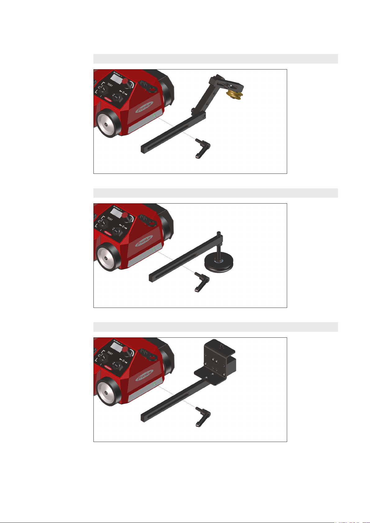
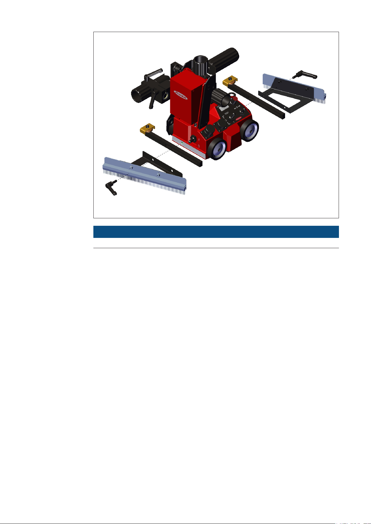
Fitting the lateral
guides (option)
All optional lateral guides for the ArcRover 15 carriage come with the M6 clamping screw
attached. The lateral guides are attached to the end faces of the carriage.
Tiltable lateral guide
Lateral guide for edge
Standard lateral guide with magnet
27
Page 28

Fitting lateral
guides with guide
rails
Lateral guide with guide rail
The exible lateral rail is secured using magnetic bases. Each rail (1850 mm) requires 10
magnetic bases to guarantee a secure hold.
The rail sections can be attached to the magnetic bases in the following ways:
- Placed end-on
- Overlapping
Attach the rails to the magnet block with the provided M5x16 xing screws.
M5x16
End-on join Overlapping join
When placed on a 5 mm thick magnetic surface, the magnetic bases have the following holding force:
- Up to a temperature of 100 °C (212 °F): 90 N
- From a temperature of 180 °C (356 °F): 54 N
28
Page 29

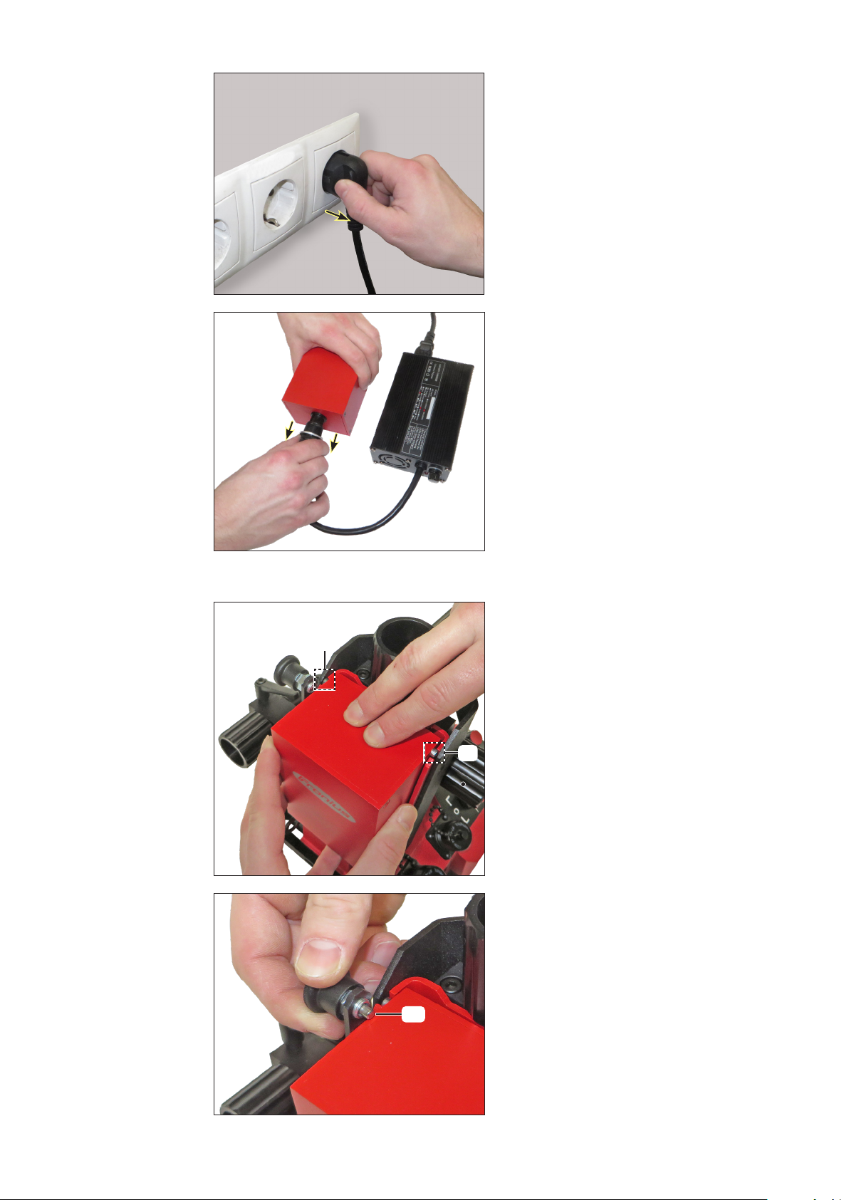
Charging the
rechargeable
battery pack
IMPORTANT! Recharge the rechargeable
battery pack after every discharge. Do not
wait until the battery pack is completely
discharged before recharging it.
1. Connect the mains cable to the charger.
2. Insert a Schuko plug into a 230 V
socket.
LED1 lights up red (mains on).
LED1 LED2
3. Connect the charging plug from the
charger to the rechargeable battery
pack. The rechargeable battery pack
is charging.
LED2 lights up red (charging process
active).
LED1 LED2
IMPORTANT! The rechargeable battery pack is fully charged after a charging time of 2
hours.
LED2 lights up green (rechargeable battery pack fully charged).
LED1 LED2
29
Page 30
Charging the
rechargeable
battery pack
(continued)
4. Disconnect the Schuko plug.
5. Remove charging plug from the re-
chargeable battery pack.
Insert rechargeable battery
pack into the
carriage
(a)
(b)
(a)
IMPORTANT! Before inserting the re-
chargeable battery pack, check that
the connection contacts are not dirty or
shorted.
1. Insert the rechargeable battery pack
from above into the compartment.
The housing screws have to sit in the
appropriate recesses on the carriage
frame (a).
2. Keep turning the lock knob until the
fuse set (b) locks.
30
Page 31
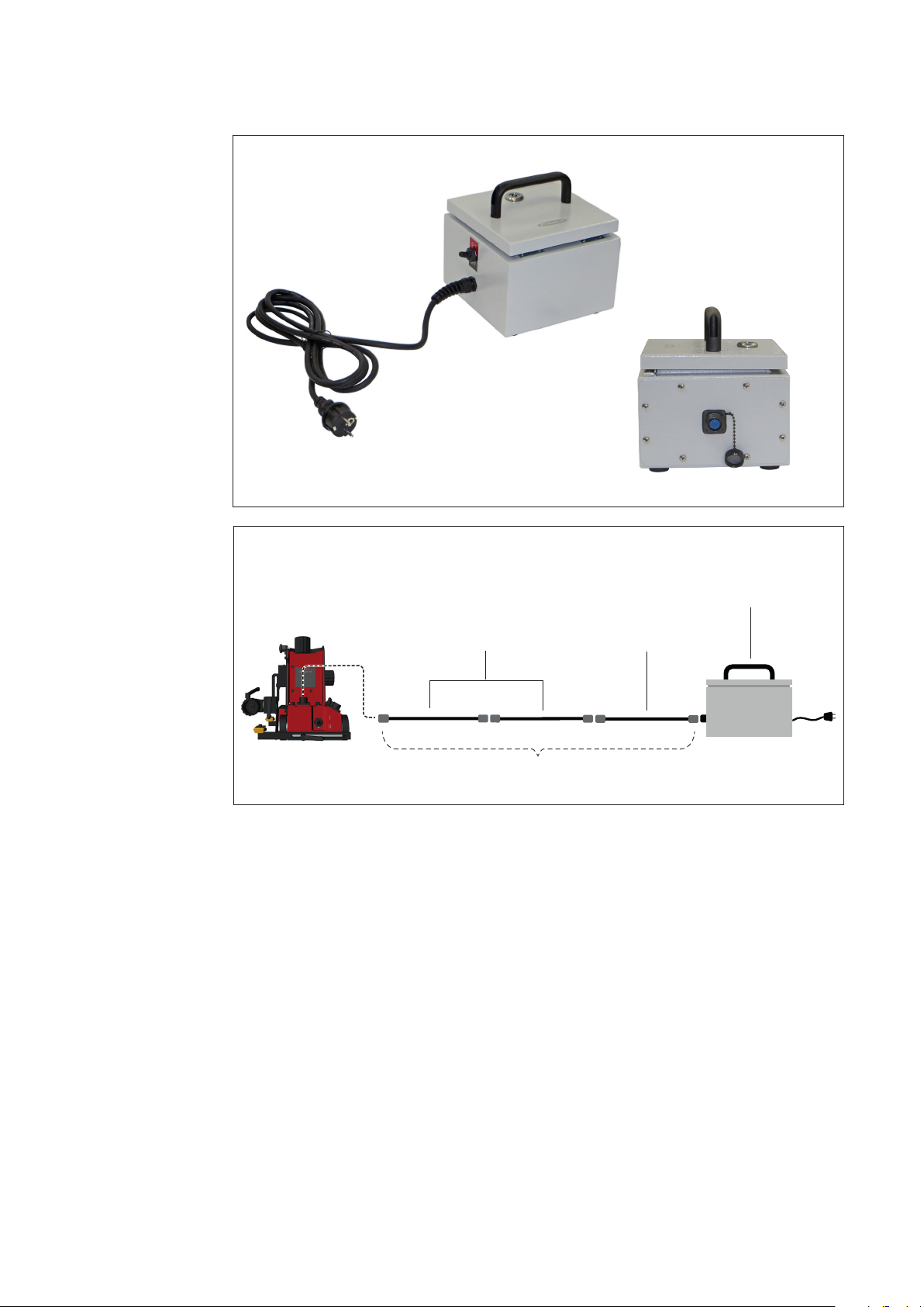
Connecting the
external power
supply (option)
With the „ArcRover 15 mains operation“ option, the carriage can be operated with an
external power supply instead of the battery pack.
External power supply
230V
Extension cable
max. 30 m
Remote control cable
10 m10 m10 m
IMPORTANT! When extending the remote control cable, observe the following points:
- use a maximum of 2 extension cables
- do not exceed total length of 30 m
- ensure that all union nuts are tightened at all connection points
31
Page 32

Setting up the carriage
Checking the
surface of the
workpiece and
the carriage to
ensure they are
clean
Placing
the carriage
Before positioning the carriage, check the following:
- The surface of the workpiece must be clean (no sand, shavings, etc.)
- The base plate of the carriage must be free of objects which can be attracted by the
magnet
- The rubber elements of the drive wheels must be undamaged and free of swarf
- The guide wheels must be clean, undamaged and free of welding spatter
WARNING!
Risk of injury due to permanent magnet.
There is a danger of injury to the ngers when positioning the carriage.
- Only hold the carriage by the handle and not by the base plate.
1. Place the carriage on the workpiece.
The side guide wheels must be in
contact with the workpiece.
2. If necessary, correct the position of the
guide wheels.
NOTE!
Detailed informations on „Setting up
the guide rails“ can be found in chapter
„Preparing the carriage“.
32
Page 33

Attaching fall
protection
(vertical operation)
IMPORTANT! In vertical operation, the carriage must be secured by a load securing
device with a locking function to prevent it from falling. The load securing device must be
designed for the total weight of the carriage. The manufacturer accepts no liability for any
damage to persons or property resulting from vertical use of the carriage without a load
securing device.
1. Attach the snap hook of the load
securing device to the lashing point for
securing the carriage.
NOTE!
Do not stand beneath a suspended
carriage.
2. Make sure the cable is kept permanently taut.
33
Page 34

Mounting and
adjusting the
welding torch
(b)
(a)
(d)
(c)
1. Turn the adjusting dial (a) to the left
and release the torch holder.
2. Insert the welding torch (b).
3. Turn the adjusting dial (a) to the right
and x the welding torch in position.
4. Set the welding torch inclination:
- Loosen the clamping lever (c)
- Twist the torch holder (d)
and set required inclination
- Tighten the clamping lever (c)
5. Release all other necessary clamping
levers and position the welding torch.
(e)
(e)
(f)
6. Turn the adjusting dial on the relevant
mechanical adjustment unit (e, f) until
the correct welding torch position is
reached.
34
Page 35

Relieving strain
on the carriage
To attain correct wirefeed, observe the following when laying the hose pack:
- Do not allow the hosepack to become
kinked
- Always lay the hosepack as straight as
possible
Handling the hosepack
1. Suspend the hosepack (it must not come into contact with the oor), use balancers
and hosepack holders (e.g. universal hosepack holder).
2. Make sure the hosepack does not become kinked. This can lead to wirefeed problems.
IMPORTANT! Observe the maximum tensile load on the torch holder (see the "Technical
data" section). This value must not be exceeded.
35
Page 36

Starting up the carriage
Checking the
connections
Switching on the
system components
The following activities and work steps apply to the fully installed system. Before startup, check all the connections between, and connection sockets of, the following system
components:
- Carriage
- Rechargeable battery pack
- Power source
- Cooling unit
- Gas cylinder
- Wirefeeder
- Welding torch with hosepack
Precise information on the assembly and connection of the system components can be
found in the relevant operating instructions for the system component.
WARNING!
Danger of injury from premature arc ignition.
The arc may be ignited accidentally. This can cause serious eye injuries.
- Before switching on the system components, make sure that the
“Start LEFT/0/RIGHT” toggle switch on the carriage control panel is set to the “0”
position.
1. Switch on the main switch on the following system components:
- Carriage control unit
- Power source
Retrieving parameter record (JOB)
on the power
source
The following appears:
2. Turn the adjusting dial and set the desired program
(e.g. program 3).
Turn
3. Press the adjusting dial once; the program is loaded.
Speed is displayed.
Press
► Load the relevant job on the control panel for the power source. More detailed
information on "Job mode" can be found in the Operating Instructions for the power
source.
When an analogue power source is being used, the requisite welding parameters
must be set manually on the power source.
36
Page 37

Setting the carriage parameters
Setting the unit 1. Press and hold the adjusting dial (a).
(a)
2. Press and hold welding toggle switch
I/0/TEST in position "TEST".
(b)
O
TEST
I
O
O
I
3. Turn the "Control unit ON/OFF" toggle switch to "ON".
Display check is carried out.
Currently set unit (e.g. inch) is displayed.
Turn
Press
4. Turn the adjusting dial and set the desired unit
(e.g. Cn).
5. Press the adjusting dial once. Setting takes eect;
program selection "SLo" is displayed.
37
Page 38

Creating
the carriage
program
Press
for 5
seconds
Turn
Press
Turn
Press
1. Press the adjusting dial for 5 seconds.
Menu is opened, "Path" parameter (Total Path) is
displayed.
2. Turn the adjusting dial and set the desired distance
(e.g. 500 cm).
3. Press the adjusting dial once. Value takes eect;
"Length" parameter (Segment Width) is displayed.
4. Turn the adjusting dial and set the desired distance
(e.g. 20.0 cm).
5. Press the adjusting dial once. Value takes eect;
"Interval" parameter (Segment Gap) is displayed.
Turn
Press
Turn
Press
6. Turn the adjusting dial and set the desired distance
(e.g. 20.0 cm).
7. Press the adjusting dial once. Value takes eect;
program selection "SLo" is displayed.
8. Turn the adjusting dial and set the desired program
number (e.g. Prg 3).
9. Press the adjusting dial once. Set parameters are
saved under the desired program number.
Current speed (Travel Speed) is displayed.
38
Page 39

Welding mode
O
TEST
I
ArcRover 22
Memory 0
CAR
OSC
ACC
000000
Memory 0
CAR
OSC
ACC
000000
O
TEST
I
ArcRover 22
Memory 0
CAR
OSC
ACC
000000
Memory 0
CAR
OSC
ACC
000000
Performing
a test run
Starting the welding process
Carry out a test run to check that all system components work together correctly. This
is performed without an arc and allows the movements during the processes to be
checked.
1. Turn welding toggle switch I/0/TEST to "0".
O
O
2. Set the "Start LEFT/0/RIGHT" toggle switch to the desired direction the test run starts. To stop the process early, turn the switch to the "0"
position.
IMPORTANT! Never leave the carriage unattended, especially when it
is moving automatically.
3. Carry out a visual inspection during the test run.
4. Make any necessary corrections (welding torch position, carriage
direction of travel, speed, oscillation motion, etc.)
1. Turn welding toggle switch I/0/TEST to "I".
O
End of welding
O
the welding process starts. To stop the process early, turn the switch
to the "0" position.
IMPORTANT! Never leave the device unattended, particularly when it
is moving automatically.
Welding stops after the following events:
- When the "Start LEFT/0/RIGHT toggle switch is activated on the control panel
- After the Total Path has run
2. Set the "Start LEFT/0/RIGHT" toggle switch to the desired direction -
39
Page 40

Troubleshooting
General
Displayed error
messages
In the event of faults, note that the functioning of the entire system depends on many
additional components (power source, wirefeeder, etc.) that are also potential sources of
problems.
If an error message that is not described here appears on the display, then the fault can
only be xed by After-Sales Service. Make a note of the error message shown and of the
serial number of the carriage, and contact the After-Sales Service team with a detailed
description of the error.
Error Cause Remedy
err1 - Save/load error. Possible
damage of the mobile controller
memory.
err2 - CAN communication systems
initialization error
err3 - Communication error
between the controller and
carriage motor controller.
err4 - Carriage motor controller
internal error.
► Contact
Fronius service technicians.
► Contact
Fronius service technicians.
► Eliminate short circuit between
cables or communication ports.
► Contact
Fronius service technicians.
Carriage
Error Cause Remedy
Drive wheels slip
during travel
Play at the
welding torch
- Wheels contaminated. ► Clean wheels.
- Carriage overloaded
- Hosepack pulls the
carriage up.
- Insucient magnetic
force.
- Magnetic force too low.
Carriage raised from the
ground by an obstacle or
unevenness
- Insucient magnetic
force.
- Magnet is overheated and
not eective - working
temperature over 150 °C.
- Play at the adjustment
units.
- Play at the
guide rails.
► Relieve load on the car-
riage. Hang hosepack.
► Sheet too thin - must be at
least 4 mm thick - change
welding conditions.
► Reduce clearance
(s < 4 mm).
► Remove the base plate
and check magnetic at-
tachment.
► Change magnet.
► Change welding condi-
tions (reduce working
temperature).
► Eliminate play: tighten
pressure screws with Allen
key.
► Tighten the clamping
screws.
40
Page 41

Carriage
(continued)
Display does not
light up
Display lit but
carriage does not
work
Power source does
not start
- Rechargeable battery
pack discharged.
► Charge up the recharge-
able battery pack with the
charger.
- Electronic module - no
power.
► Check the connections
between the compartment
and the electronic module.
- Electronic module damaged.
- Traverse Speed is set to
► Change the electronic
module.
► Adjust Traverse Speed.
"0".
- Drive system faulty. ► Remove the cover and
check the operation of the
drive system.
- "Welding I/0/TEST" toggle
switch is in the "0" posi-
► Turn toggle switch to the
"I" position.
tion.
- Connecting cable
between carriage and
► Check connecting cable.
Replace if necessary.
power source is damaged.
41
Page 42

Maintenance
Personnel
Maintenance
record
Cleaning
WARNING!
Risk of injury and damage from incorrectly performed maintenance work.
It is essential to adhere to the maintenance intervals and maintenance procedures.
The manufacturer accepts no liability for any damage caused by inadequate or poorly
performed maintenance.
- All maintenance work on the carriage must only be carried out by trained
technicians.
The operator of the carriage is responsible for correctly keeping a service book with the
following information as a minimum:
- Date
- Operator
- Maintenance work carried out
- Use a clean, dry cloth to clean the components. Only use a dierent cleaning agent if
this is indicated in the maintenance procedure for a specic component.
- Remove the rechargeable battery pack before carrying out any maintenance operations.
Maintenance
intervals
Recommended
lubricants
D Daily
W Weekly
M Monthly
1/4 Y Quarterly
1/2 Y Half-yearly
Y Annually
IMPORTANT! Lubricants with solid lubricant additives (e.g. MoS2, graphite and PTFE)
are not suitable for the guide systems.
Lubricant DIN DIN number Comment
Grease KP 2-K 51502/51825 Lithium soap grease
Lubricating oil CLP32-100 51517 Part 3 ISO VG 32-100
42
Page 43
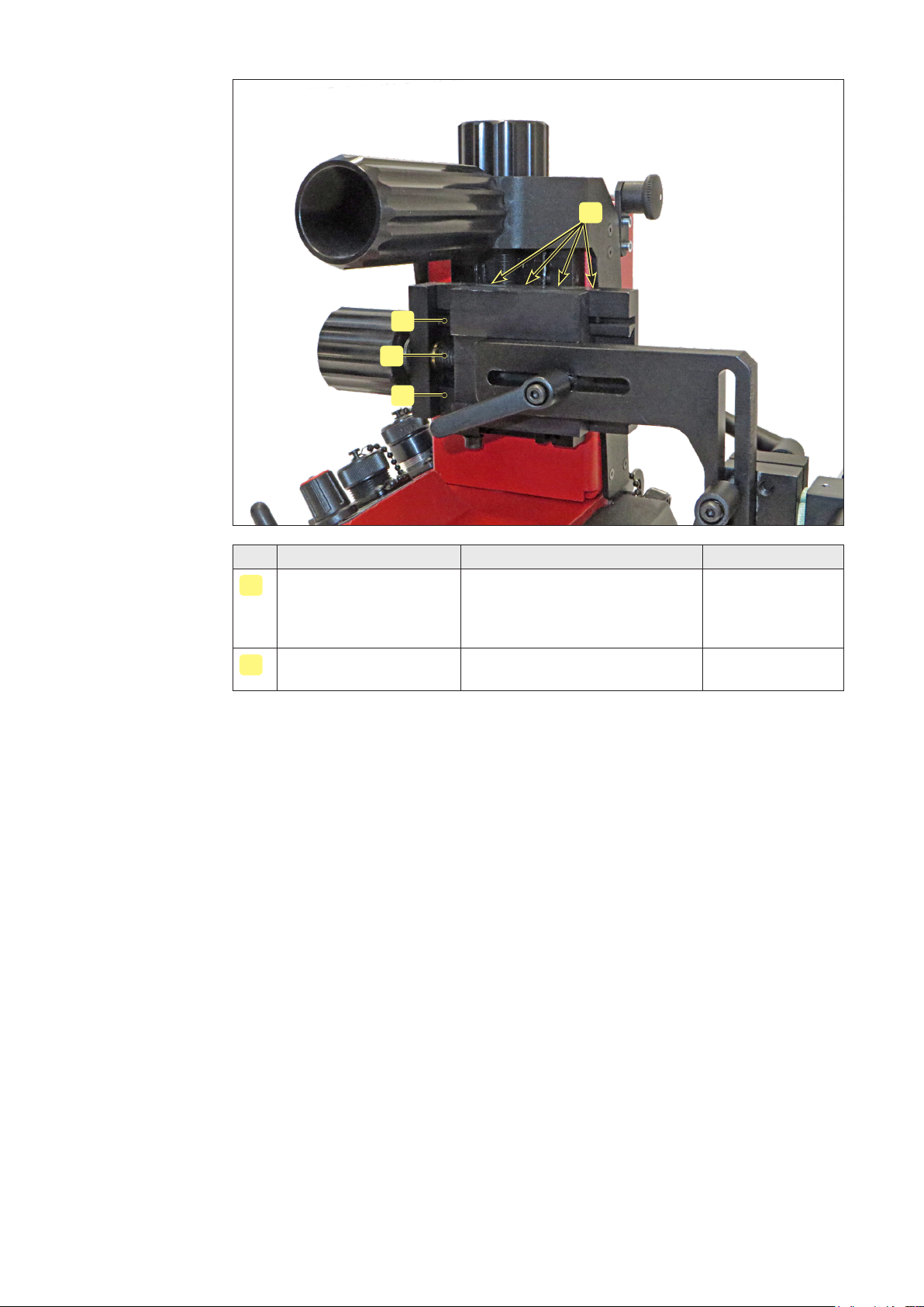
Horizontal
welding torch
adjustment unit
A
A
B
A
Item Component Measure Interval
Linear guides ► Clean
A
1/2 Y
► Check oil lm
► Eliminate play: tighten pres-
sure screws with Allen key
Threaded spindle ► Check
B
► Clean, regrease
M
1/4 Y
43
Page 44

Vertical
welding torch
adjustment unit
A
B
A A
Item Component Measure Interval
Linear guides ► Clean
A
1/2 Y
► Check oil lm
► Eliminate play: tighten pres-
sure screws with Allen key
Threaded spindle ► Check
B
► Clean, regrease
M
1/4 Y
44
Page 45

Carriage front
Carriage back
K
K
E
K K
Item Component Measure Interval
Rollers and rails ► Clean
E
1/4 Y
► Position check
Wheels, underbody,
K
► Clean T
guide rails
K
E
K
K
Item Component Measure Interval
Rollers and rails ► Clean
E
1/4 Y
► Position check
Wheels, underbody,
K
► Clean T
guide rails
45
K
Page 46
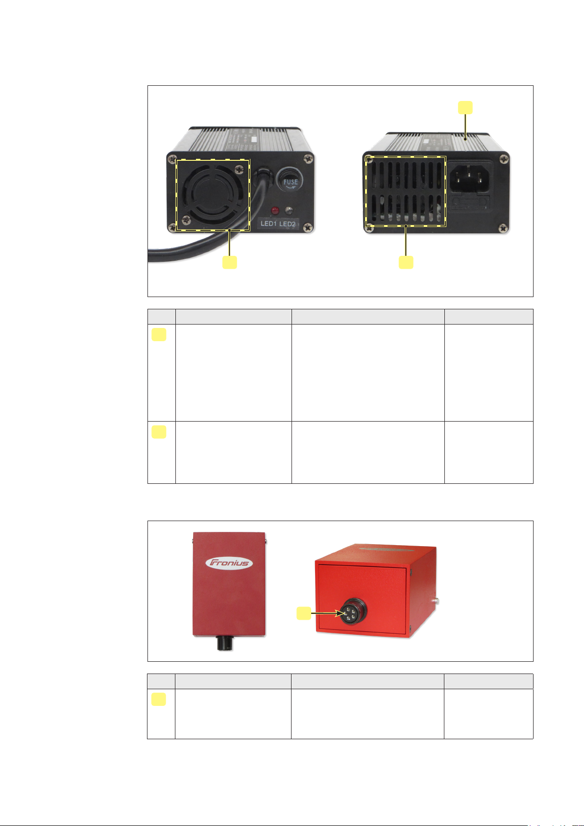
Charger
These devices are largely maintenance-free. To ensure problem-free operation, observe
the following instructions:
L
II
Item Component Measure Interval
Ventilation openings
I
(air inlet, air outlet)
► Keep clean to ensure that
cooling air is able to circu-
M
late. Danger of short circuiting! Make sure that no metal
objects, such as metal chips,
penetrate the interior of the
device through the ventilation
openings.
Aluminium housing ► Place in a well-ventilated and
L
-
dry area.
► The aluminium hosing func-
tions as a heat sink - do not
cover.
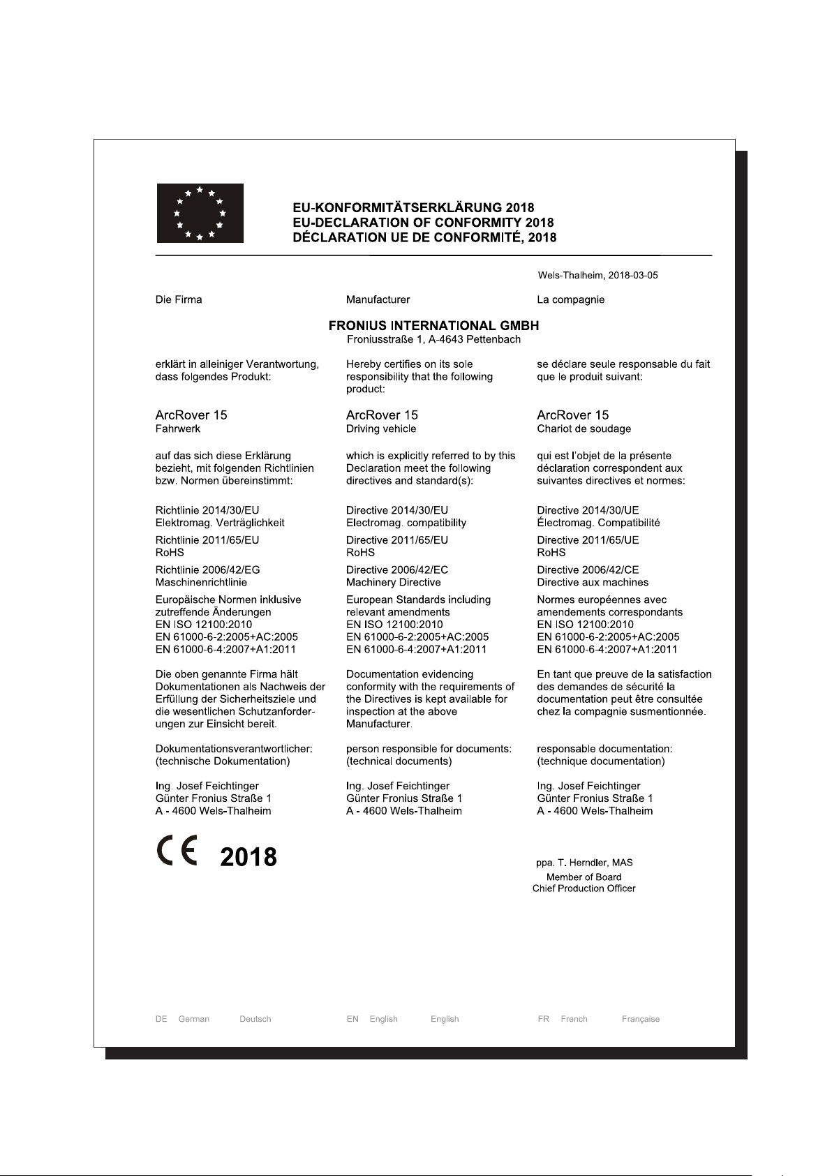
Rechargeable
battery pack
J
Item Component Measure Interval
Connection contacts ► Visual inspection before
J
W
plugging in
► Protect against contamina-
tion
46
Page 47

Disposal of
components
WARNING!
Danger of environmental damage!
Incorrect disassembly and disposal of the individual carriage components can result in
serious environmental damage.
- The product must only be disposed of by trained and qualied personnel.
Ensure that:
- All machine components and electrical parts are separated according to type and
disposed of properly
- Exhausted or defective battery packs are disposed of by the dealer, Fronius Customer
Service or at disposal sites approved by the relevant public authority. The rechargeable battery packs are then recycled.
NOTE!
If you have any further questions about disposal/recycling, please contact the manufacturer.
47
Page 48

Technical Data
ArcRover 15
carriage
Maximum load capacity (horizontal) 15 kg (33.07 lb)
Maximum load capacity (vertical) 15 kg (33.07 lb)
Max. tensile load on the torch holder: A 50 mm (1.97 in.)
B 80 mm (3.15 in.)
Horizontal:
C 15 kg (33.07 lb)
D 12 kg (26.46 lb)
Vertical:
E 10 kg (22.05 lb)
F 8 kg (17.64 lb)
A
C
A B
D
B
E
F
Charger supply voltage (50 - 60 Hz) 230 V AC
Carriage supply voltage (rechargeable battery
pack)
Energy consumption 39 W
Battery capacity 3.35 Ah
Battery charging time 2 h
Min. battery capacity approx. 8 hrs
Net weight including rechargeable battery pack 7.1 kg (15.65 lb)
Degree of protection (carriage) IP 23
Degree of protection (rechargeable battery pack) IP 20
Welding positions (horizontal/vertical) PA, PB, PC, PF, PG
Horizontal speed (load = 85 N) 5 - 250 cm/min (+/- 2%)
Vertical speed (load = 85 N) 5 - 250 cm/min (+/- 4%)
Adjustable range of torch (horizontal/vertical) 30 mm / 30 mm (1.18 in / 1.18 in.)
25.4V DC
48
Page 49

ArcRover 15
carriage
(continued)
ArcRover 15
dimensions
Welding torch neck diameter max. 28 mm (max. 1.10 in)
Minimal material thickness 4 mm (0.16 in.)
Clearance 4 mm (0.16 in.)
Max. preheating temperature of the workpiece 150 °C (302 °F)
A
B C
Environmental
conditions
D
ArcRover 15 carriage
A 255 mm 10.0 in
B 275 mm 10.8 in
C Min. 198 mm
Max. 313 mm
D Min. 253 mm
Max. 335 mm
Min 7.8 in
Max 12.3 in
Min 10.0 in
Max 13.2 in
Operating, storing or transporting the system outside the specied area or environmental ranges is regarded as not complying with the intended purpose. The manufacturer
shall not be liable for any damage or loss resulting from this.
Ambient air temperature range:
- during operation: 0 °C to +40 °C (32 °F to 104 °F)
- during transport and storage: -10 °C to+45 °C (14 °F to 113 °F)
- Recommended temperature range during charging: +5 °C to +40 °C (41 °F to
104 °F)
Relative humidity:
- up to 65% +/- 20%
Environmental conditions:
- Surrounding air is free from dust and ammable vapours, solvents or gases.
- No strong vibrations and magnetic elds around the rechargeable battery pack.
- No direct sunlight on the rechargeable battery pack.
- No storing the rechargeable battery pack on moist or wet surfaces.
49
Page 50

Spare parts
Spare parts,
wearing parts
and auxiliary
materials
Details required
when placing
orders
Using spare parts and wearing parts from third-party manufacturers may pose risks. Use
the prescribed Fronius original spare parts only.
The manufacturer cannot accept any liability for damage resulting from the use of spare
or wearing parts or auxiliary materials that are not approved by the manufacturer.
NOTE!
Parts must be replaced by trained personnel only.
When ordering spare parts, you should provide the following data:
- Exact designation of the spare part
- Corresponding item number as per Spare Parts List
- Model name of the device
- Serial number of the device (shown on the rating plate)
50
Page 51

ArcRover 15 carriage 8,045,645
51
Page 52

ArcRover 15 carriage 8,045,645
Item Designation Item number Pcs
(1) Rechargeable battery pack 48,0005,2600 1
(2) Torch body assembly 48,0005,2637 1
(3) Universal welding torch holder 48,0005,2638 1
(4) Welding torch adjustment unit (horizontal, vertical) 48,0005,2639 1
(5) Lashing point for securing the carriage 48,0005,2640 2
(6) Protective plate for wheels 48,0005,2641 1
(7) Guide rail assembly (left, right) 48,0005,2642 2
(8) Carriage frame assembly 48,0005,2643 1
(9) Connection set (rechargeable battery pack) 48,0005,2644 1
(10) Toggle switch set (control unit ON/OFF) 48,0005,2645 1
(11) Connection set (power source control) 48,0005,2646 1
(12) Connection set (CAN communication) 48,0005,2647 1
(13) Toggle switch set (welding I/0/TEST) 48,0005,2648 1
(14) Toggle switch set (Start LEFT/0/RIGHT) 48,0005,2649 1
(15) Drive module 48,0005,2650 1
(16) Central processing unit 48,0005,2651 1
(17) Drive unit assembly 48,0005,2652 1
(18) Drive wheel assembly 48,0005,2653 1
(19) Base assembly 48,0005,2654 1
(20) Charger 48,0005,2601 1
(21) Torch holder uptake assembly 48,0005,0134 1
52
Page 53

„External power supply“ option
(1)
(2)
(3) (4)
10 m10 m10 m
max. 30 m
Item Designation Item number Pcs
(1) Control box with external power supply 48,0005,0165 1
(2) Power supply 230V AC - 24V DC/ 5A 48,0005,1818 1
(3) Extension cable 10 m 38,0100,0476 1
(4) Remote control cable 10 m 38,0100,0433 1
53
Page 54

Circuit Diagrams
BATTERY PACK
+25,2V
GND
E
D
C
B
AA
B
MAIN SWITCH
E
C
D
E
+25,2V
D
GND
CANL
CANH
B
A C
54
CONTROL
PANEL
DRIVE
MODULE
CARRIAGE
Page 55

MAIN SWITCH
ARC Ignition
EDCBA
blue
red
GND
2
blue
1
blue
1 2 3 4
ARC
IGNITION
RELAY
619.01.01.04.0
WeldTest
WeldON
red
blue
GND
blue
red
2
1
25,2V
CONTROL MODULE
S5
GND
S3S1 S2 S4
GND
DirPos
DirNeg
619.01.01.07.0
GND
+25,2V
CANH
CANL
619.01.01.09.0
3
brown
2
white
1
blue
619.01.01.05.0
3
blue
2
green
1
grey
619.01.01.06.0
4
blue
3
red
2
white
1
green
2
2
3
ARC ENABLE
3
1 1
SWITCH
TRAVEL SWITCH
25.2V
/3.2
GND
/3.2
CAN_L
/3.2
CAN_H
/3.2
A B C D E
625.01.01.04.0
55
CONTROL
PANEL
Page 56

MODULE
619.01.02.10.0
brown
MOTOR
ENCODER
DC
MOTOR
S7
GND
Din0
+24V
blue
S8
1
GND
2
DOUT0
BRAKE
1
2
3
S6
1
GND
2
Din1
3
+24V
DC
MOTOR
1
2
3
4
5
6
7
8
9
10
A
B
619.01.02.13.0
red
black
S4
1
+5V
2
Enc B
3
Enc A
4
GND
S3
1
+5V
2
Hall H3
3
Hall H2
4
Hall H1
5
GND
S5
1
MD
2
MC
3
MB
4
MA
DRIVER
DRIVE
/2.3
CAN_H
/2.3
CAN_L
/2.3
GND
/2.3
25.2V
625.01.01.04.0
56
white
green
blue
red
S2
1
CANH
2
CANL
+24V
GND
PE
1
Up
S1
3
2
4
Page 57

PACK
A
B
619.08.06.00.0
C
D
E
black
red
BATTERY
619.08.07.00.0
black
red
BATTERY
57
Page 58
EU Declaration of Conformity
58
Page 59
59
Page 60

60
Page 61

FRONIUS INTERNATIONAL GMBH
TechSupport Automation
E-Mail: support.automation@fronius.com
www.fronius.com
www.fronius.com/addresses
61
Page 62

 Loading...