


Application Guide PV Point Fronius
GEN24 Plus Series
Application Guide
© Fronius International GmbH
Version 2 06/2022
Fronius reserves all rights, in particular rights of reproduction, distribution and translation.
No part of this work may be reproduced in any way without the written consent of Fronius. It must not be saved, edited,
reproduced or distributed using any electrical or electronic system.
You are hereby reminded that the information published in this document, despite exercising the greatest of care in its
preparation, is subject to change and that neither the author nor Fronius can accept any legal liability
Gender-specific wording refers equally to female and male form.
1/10

1 INTRODUCTION
The PV point represents the basic emergency power function of the GEN24 Plus series and is integrated as
standard ex factory .It is a s socket that is only supplied in case of grid outage based on the currently available
PV generator power (or available battery). The switch happens automatically by the inverter and doesn’t require
any additional grid separation components. Every important single phase consumer in the household up to 3 kW
can be supplied by the PV point. A PV point installation does not (necessarily) require battery storage – an
installation of a storage unit is optional. The function of the PV point is depicted in Picture 1.
Picture 1: Scheme of the basic emergency power function (PV Point) of the Fronius GEN24 Plus Series
2 INSTALLATION
2.1 Preparation of the hardware
The installation of the PV Point requires a modification of the base unit. For this there are four predefined exit
points marked on the bottom of the inverter, which can be used for the PV point installation. The bottom of the
GEN24 Plus series including the exit points is shown in Picture 2.
Picture 2: Bottom of the GEN24 Plus inverter series including the four predefined markings for the exits.
2/10
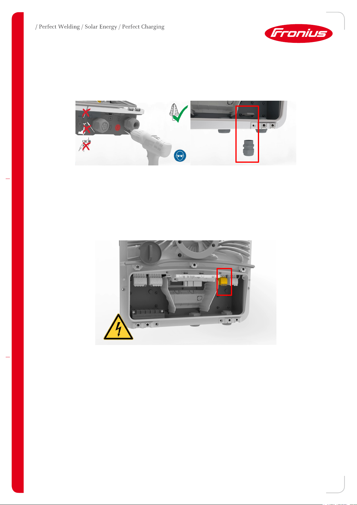
The first step consists of drilling through one of the four exit points on the base unit. It would be recommended
to use a step drill (M16 / 16 mm diameter). As soon as the drilling is finished, a PG screw connection should be
inserted on the modified area, in order to ensure the highest safety class IP66. The drilling process as well as
the base unit with the inserted PG screw connection can be seen in Picture 3.
Picture 3: Drilling the base unit and inserting PG-screw connection at the modified area.
2.2 Cabling
After successfully inserting the cable gland, the cable can be pulled through and connected to the inverter. The
GEN24 Plus series has its own intended exit / own push in spring clamp for the PV point on the AC side, that is
depicted in Picture 4.
Picture 4: Fronius GEN24 Plus connection area with the PV point push in spring clamp
The push in spring clamp is distinguished by its easy usability, which enables a fast installation. When installing
the PV point there are no special tools nor adding wire end ferrules to the cable required. Regarding cables
2
Fronius recommends the usage of a copper cable with a cable cross section of min. 1,5 mm
to max. 10 mm
for direct connection to the inverter. Picture 5 shows the requirements for the cables as well as the handling
and the functionally of the push in spring clamp:
3/10
2
 Loading...