

Page 1

Fronius prints on elemental chlorine free paper (ECF) sourced from certified sustainable forests (FSC).
/ Perfect Charging / Perfect Welding / Solar Energy
AI IO/i V2
AI IO/i V2
Bedienungsanleitung
DE
Roboter-Option
Operating instructions
Robot option
EN-US
42,0410,2502 003-15072020
Page 2

Page 3

Inhaltsverzeichnis
Allgemeines 4
Allgemeines 4
Systemübersicht 4
Lieferumfang 4
Technische Daten 4
Signalbeschreibungen 5
Sicherheit 6
Sicherheit 6
Umgebungsbedingungen 6
Anschlüsse und Anzeigen 7
Anschlussbelegung 7
Anzeigen am Interface 8
Installation 9
Interface auf Hutschiene montieren 9
Interface anschließen 9
SmartManager - Die Webseite der Stromquelle 10
Die Webseite der Stromquelle 10
SmartManager der Stromquelle aufrufen und anmelden 10
DE
3
Page 4

Allgemeines
(1) (2) (3)
(1)
(2) (3)
Allgemeines Die digitalen Eingänge und Ausgänge sind wie folgt galvanisch getrennt:
- gegenseitig
- gegenüber dem Anschluss SpeedNet und dem Schweißpotential
- für einen maximalen Spannungsunterschied von 100 V
Systemübersicht
Lieferumfang
(1) Automatensteuerung
(2) Interface
(3) Stromquelle mit optionalem Anschluss SpeedNet an der Geräterückseite
(1) Interface
(2) Bedienungsanleitung
(3) Tragschienenhalter mit Schrau-
ben
Technische Daten
4
Versorgungsspannung + 24 V
Schutzart IP 44
Page 5

Signalbeschreibungen
Den nachfolgenden Link in den Internet-Browser eingeben, um zu den Signalbeschreibungen zu gelangen:
manuals.fronius.com/html/4204260227
DE
5
Page 6

Sicherheit
Sicherheit
Umgebungsbedingungen
WARNUNG!
Gefahr durch Fehlbedienung und fehlerhaft durchgeführte Arbeiten.
Schwerwiegende Personen- und Sachschäden können die Folge sein.
Alle in diesem Dokument beschriebenen Arbeiten und Funktionen dürfen nur von
▶
geschultem Fachpersonal ausgeführt werden.
Dieses Dokument lesen und verstehen.
▶
Sämtliche Bedienungsanleitungen der Systemkomponenten, insbesondere Sicher-
▶
heitsvorschriften lesen und verstehen.
WARNUNG!
Gefahr durch unplanmäßige Signalübertragung.
Schwerwiegende Personen- und Sachschäden können die Folge sein.
Über das Interface keine sicherheitsrelevanten Signale übertragen.
▶
VORSICHT!
Gefahr durch unzulässige Umgebungsbedingungen.
Schwere Geräteschäden können die Folge sein.
Das Gerät nur bei den nachfolgend angegebenen Umgebungsbedingungen lagern
▶
und betreiben.
Temperaturbereich der Umgebungsluft:
- beim Betrieb: 0 °C bis + 40 °C (32 °F bis 104 °F)
- bei Transport und Lagerung: -25 °C bis +55 °C (-13 °F bis 131 °F)
Relative Luftfeuchtigkeit:
- bis 50 % bei 40 °C (104 °F)
- bis 90 % bei 20 °C (68 °F)
Umgebungsluft: frei von Staub, Säuren, korrosiven Gasen oder Substanzen, usw.
Höhenlage über dem Meeresspiegel: bis 2000 m (6500 ft).
Das Gerät vor mechanischer Beschädigung geschützt aufbewahren/betreiben.
6
Page 7

Anschlüsse und Anzeigen
Anschlussbelegung
Pin Ausgang Signal Beschaltung
DE
Ausgangssignale:
(1) OUT 1 Process active Versorgung für Signal
(2) OUT 1 Process active Signal
(11) OUT 2 Power source ready Versorgung für Signal
(12) OUT 2 Power source ready Signal
Eingangssignale:
Pin Eingang Signal Potential
(3) IN 1 Welding start GND Wird Pin (3) belegt, muss
(4) IN 1 Welding start + 24 V bis
+ 36 V
(5) IN 2 nicht belegt GND Wird Pin (5) belegt, muss
(6) IN 2 nicht belegt + 24 V bis
+ 36 V
(7) IN 3 nicht belegt GND Wird Pin (7) belegt, muss
(8) IN 3 nicht belegt + 24 V bis
+ 36 V
(9) IN 4 nicht belegt GND Wird Pin (9) belegt, muss
(10) IN 4 nicht belegt + 24 V bis
+ 36 V
auch Pin (4) belegt werden!
auch Pin (6) belegt werden!
auch Pin (8) belegt werden!
auch Pin (10) belegt werden!
7
Page 8

Anzeigen am
Interface
(1) LED OUT 1
leuchtet grün;
zeigt an, dass der Ausgang mit
Spannung versorgt wird
(2) LED OUT 2
leuchtet grün;
zeigt an, dass der Ausgang aktiv
ist - das Signal „Prozess aktiv“ ist
gesetz
(3) LED IN 1
leuchtet grün;
zeigt an, dass der Eingang aktiv ist
(4) LED IN 2
leuchtet grün;
zeigt an, dass der Eingang aktiv ist
(5) LED IN 3
leuchtet grün;
zeigt an, dass der Eingang aktiv ist
(6) LED IN 4
leuchtet grün;
zeigt an, dass der Eingang aktiv ist
(7) LED IN STATUS
leuchtet grün;
zur Statusanzeige mittels BlinkCode
(8) LED IN ERROR
leuchtet grün;
zur Fehleranzeige mittels BlinkCode
(9) LED IN +24V
leuchtet grün;
leuchtet, sobald das Interface versorgt wird
8
Page 9

Installation
0,5Nm
DE
Interface auf Hutschiene montieren
Das Interface muss nicht auf einer Hutschiene montiert werden.
In jedem Fall die Angaben bezüglich der Umgebungsbedingungen befolgen - siehe
hierfür Abschnitt Umgebungsbedingungen auf Seite 6.
1 2
Interface
anschließen
Um das Interface an der Stromquelle anschließen zu können, muss die Stromquelle über
einen optionalen Anschluss SpeedNet an der Geräterückseite verfügen.
Die Anschlussklemme (1) vom Inter-
1
face an die Automatensteuerung
anschließen - gemäß der Beschreibung der Anschlussbelegung und der
Beschriftung der Kabel des Interfaces
Den Stecker SpeedNet (2) vom Inter-
2
face an den Anschluss SpeedNet (3)
der Stromquelle anschließen
9
Page 10

SmartManager - Die Webseite der Stromquelle
3
2
1
4
xx.x.xxx.x
1.9.0-16501.9508
Die Webseite der
Stromquelle
SmartManager
der Stromquelle
aufrufen und
anmelden
Die Stromquelle verfügt über eine eigene Webseite, den SmartManager.
Sobald die Stromquelle in einem Netzwerk integriert ist, kann der SmartManager über
die IP-Adresse der Stromquelle aufgerufen werden.
Abhängig von Anlagenkonfiguration und Software-Erweiterungen enthält der SmartManager folgende Einträge:
- Übersicht
- Update
- Screenshot
- Sichern & Wiederherstellen
- Funktionspakete
- Job-Daten
- Kennlinienübersicht
- AI IO/i V2
Voreinstellungen / System / Information ==> IP-Adresse der Stromquelle notieren
1
IP-Adresse im Suchfeld des Browsers eingeben
2
Benutzername und Kennwort eingeben
3
Werkseinstellung:
Benutzername = admin
Kennwort = admin
Angezeigten Hinweis bestätigen
4
Der SmartManager der Stromquelle wird angezeigt.
10
Page 11

Table of contents
General 12
General 12
System Overview 12
Scope of Supply 12
Technical Data 12
Signal descriptions 13
Safety 14
Safety 14
Environmental Conditions 14
Connections and Indicators 15
Pin Assignment 15
Indicators on the Interface 16
Installation 17
Mounting the Interface on a DIN Rail 17
Connecting the Interface 17
SmartManager – The Website of the Power Source 18
The Website of the Power Source 18
Opening and Logging into the SmartManager for the Power Source 18
EN-US
11
Page 12

General
(1) (2) (3)
(1)
(2) (3)
General The digital inputs and outputs are galvanically isolated as follows:
- Mutually
- From the SpeedNet connection and the welding potential
- For a maximum difference in voltage of 100 V
System Overview
Scope of Supply
(1) Machine controls
(2) Interface
(3) Power source with optional SpeedNet connection on the rear of the device
(1) Interface
(2) Operating Instructions
(3) Bearing rail holder with screws
Technical Data
12
Supply voltage + 24 V
Protection class IP 44
Page 13

Signal descriptions
Enter the following link into your Internet browser to view the signal descriptions:
manuals.fronius.com/html/4204260227
EN-US
13
Page 14
Safety
Safety
Environmental
Conditions
WARNING!
Danger from incorrect operation and work that is not carried out properly.
Serious injury and damage to property may result.
All the work and functions described in this document must only be carried out by
▶
trained and qualified personnel.
Read and understand this document.
▶
Read and understand all the Operating Instructions for the system components,
▶
especially the safety rules.
WARNING!
Danger from unplanned signal transmission.
Serious injury and damage to property may result.
Do not transfer safety signals via the interface.
▶
CAUTION!
Danger from prohibited environmental conditions.
This can result in severe damage to equipment.
Only store and operate the device under the following environmental conditions.
▶
Temperature range of ambient air:
- during operation: 0 °C to +40 °C (32 °F to 104 °F)
- During transport and storage: -25 °C to +55 °C (-13 °F to 131 °F)
Relative humidity:
- Up to 50% at 40 °C (104 °F)
- Up to 90% at 20 °C (68 °F)
Ambient air: free of dust, acids, corrosive gases or substances, etc.
Altitude above sea level: up to 2000 m (6500 ft).
Protect the device from mechanical damage during storage and operation.
14
Page 15

Connections and Indicators
Pin Assignment
Pin Output Signal Configuration
EN-US
Output signals:
(1) OUT 1 Process active Supply for signal
(2) OUT 1 Process active Signal
(11) OUT 2 Power source ready Supply for signal
(12) OUT 2 Power source ready Signal
Input signals:
Pin Input Signal Potential
(3) IN 1 Welding start GND If pin (3) is assigned, pin (4)
(4) IN 1 Welding start + 24 V to
+ 36 V
(5) IN 2 Not assigned GND If pin (5) is assigned, pin (6)
(6) IN 2 Not assigned + 24 V to
+ 36 V
(7) IN 3 Not assigned GND If pin (7) is assigned, pin (8)
(8) IN 3 Not assigned + 24 V to
+ 36 V
(9) IN 4 Not assigned GND If pin (9) is assigned, pin
(10) IN 4 Not assigned + 24 V to
+ 36 V
must be also be assigned!
must be also be assigned!
must be also be assigned!
(10) must be also be assigned!
15
Page 16

Indicators on the
Interface
(1) OUT 1 LED
Lights up green;
indicates that the output is being
supplied with voltage
(2) OUT 2 LED
Lights up green;
Indicates that the output is active –
the "Process active" signal is set
(3) IN 1 LED
Lights up green;
indicates that the input is active
(4) IN 2 LED
Lights up green;
indicates that the input is active
(5) IN 3 LED
Lights up green;
indicates that the input is active
(6) IN 4 LED
Lights up green;
indicates that the input is active
(7) IN STATUS LED
Lights up green;
indicates the status using a flash
code
(8) IN ERROR LED
Lights up green;
displays errors using a flash code
(9) IN +24V LED
Lights up green;
lights up as soon as the interface
is supplied with voltage
16
Page 17

Installation
0,5Nm
Mounting the
Interface on a DIN
Rail
The interface must not be mounted on a DIN rail.
The information regarding the environmental conditions must be observed at all times see section Environmental Conditions on page 14.
1 2
EN-US
Connecting the
Interface
In order to be able to connect the interface to the power source, the power source must
have an optional SpeedNet connection on the rear of the device.
Connect the terminal (1) from the
1
interface to the machine controls in
accordance with the description of the
pin assignment and the labeling on the
interface cable
Connect the SpeedNet connector (2)
2
from the interface to the SpeedNet
connection (3) on the power source
17
Page 18
SmartManager – The Website of the Power Source
3
2
1
4
xx.x.xxx.x
1.9.0-16501.9508
The Website of
the Power Source
Opening and
Logging into the
SmartManager
for the Power
Source
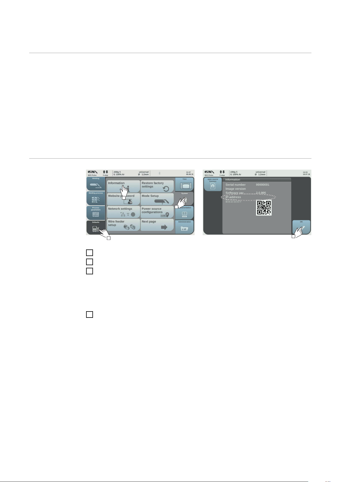
The power source has its own website, the SmartManager.
As soon as the power source has been integrated into a network, the SmartManager can
be opened via the IP address of the power source.
Depending on the system configuration and software upgrades, the SmartManager may
contain the following entries:
- Overview
- Update
- Screenshot
- Save and restore
- Function packages
- Job data
- Overview of characteristics
- AI IO/i V2
Presettings/System/Information ==> note down IP address of power source
1
Enter the IP address into the search field of the browser
2
Enter username and password
3
Factory setting:
Username = admin
Password = admin
Confirm displayed message
4
The SmartManager of the power source is displayed.
18
Page 19

EN-US
19
Page 20

FRONIUS INTERNATIONAL GMBH
Froniusstraße 1
A-4643 Pettenbach
AUSTRIA
contact@fronius.com
www.fronius.com
Under www.fronius.com/contact you will find the addresses
of all Fronius Sales & Service Partners and locations.
 Loading...