

Page 1

/ Perfect Charging / Perfect Welding / Solar Energy
Fronius Agilo
75.0-3 / 100.0-3
Operating Instructions
EN
Grid-connected inverter
42,0426,0127,EN 008-26032015
Page 2

0
Page 3

Dear reader,
Introduction Thank you for the trust you have placed in our company and congratulations on buying this
high-quality Fronius product. These instructions will help you familiarise yourself with the
product. Reading the instructions carefully will enable you to learn about the many different
features it has to offer. This will allow you to make full use of its advantages.
Please also note the safety rules to ensure greater safety when using the product. Careful
handling of the product will repay you with years of safe and reliable operation. These are
essential prerequisites for excellent results.
EN
1
Page 4

2
Page 5

Contents
Safety rules ................................................................................................................................................ 7
General information 11
Protection of people and equipment .......................................................................................................... 13
Safety.................................................................................................................................................... 13
Protection of people and equipment ..................................................................................................... 13
Galvanic (electrical) isolation ................................................................................................................ 13
Monitoring the grid ................................................................................................................................ 13
Warning notices on the device.............................................................................................................. 14
Proper use ................................................................................................................................................. 16
Proper use ............................................................................................................................................ 16
Application area ................................................................................................................................... 16
Regulations governing the photovoltaic system.................................................................................... 16
Functional principle .................................................................................................................................... 17
Functional principle ............................................................................................................................... 17
Cooling of the inverter through forced-air ventilation ............................................................................ 17
Power derating...................................................................................................................................... 17
Solar module grounding........................................................................................................................ 17
The inverter in a photovoltaic system ........................................................................................................ 18
General ................................................................................................................................................. 18
Tasks .................................................................................................................................................... 18
Converting DC to AC current ................................................................................................................ 18
Display function and data communication ............................................................................................ 18
System add-on...................................................................................................................................... 18
Description of the device............................................................................................................................ 19
Outside of inverter................................................................................................................................. 19
Inside the inverter ................................................................................................................................. 20
Connection compartment...................................................................................................................... 21
Data communication area ..................................................................................................................... 22
Possible relay contact functions............................................................................................................ 24
Data communication and Solar Net ........................................................................................................... 26
Solar Net and data interface ................................................................................................................. 26
Overcurrent and undervoltage cut-out .................................................................................................. 26
Description of the 'Fronius Solar Net' LED............................................................................................ 26
Example ................................................................................................................................................ 27
EN
Installation and commissioning 29
Choice of location ...................................................................................................................................... 31
General comments regarding choice of location...................................................................................31
Cabling into the inverter ........................................................................................................................ 31
Criteria influencing choice of location ................................................................................................... 31
Unsuitable locations.............................................................................................................................. 32
Transport.................................................................................................................................................... 33
Transport............................................................................................................................................... 33
Transporting by its lifting eyes using a crane........................................................................................ 33
Transporting by crane using pallet fork................................................................................................. 33
Transporting by forklift truck or lift truck ................................................................................................ 34
Manual transport ................................................................................................................................... 34
Positioning the inverter .............................................................................................................................. 35
Prerequisites ......................................................................................................................................... 35
Positioning the inverter ......................................................................................................................... 35
Notes regarding the air supply and the connection of an exhaust duct ................................................ 36
Connecting the inverter to the public grid (AC) .......................................................................................... 37
Monitoring the grid ................................................................................................................................ 37
Mains connections ................................................................................................................................ 37
Connecting aluminium cables ............................................................................................................... 37
Max. cross-section of AC cables........................................................................................................... 37
Safety.................................................................................................................................................... 38
3
Page 6

Connecting the inverter to the public grid ............................................................................................. 38
Connecting AC cables with a cable lug................................................................................................. 40
Maximum fuse rating on alternating current side .................................................................................. 41
Connecting an external AC supply for the inverter ...............................................................................41
Fitting and connecting optional overvoltage protection.............................................................................. 42
General ................................................................................................................................................. 42
Safety.................................................................................................................................................... 42
Fitting and connecting overvoltage protection on the DC side.............................................................. 42
Fitting and connecting overvoltage protection on the AC side.............................................................. 43
Fitting and connecting overvoltage protection for the AC- supply......................................................... 43
Connecting the DC cable to the inverter .................................................................................................... 45
General comments regarding solar modules ........................................................................................45
DC connections..................................................................................................................................... 45
Connecting aluminium cables ............................................................................................................... 45
Max. cross-section of DC cables .......................................................................................................... 45
Safety.................................................................................................................................................... 46
Connecting DC cables .......................................................................................................................... 46
Connecting DC cables with a cable lug ................................................................................................ 47
Fuse protection against polarity reversal of DC cables......................................................................... 47
Grounding the solar modules in the inverter .............................................................................................. 48
General ................................................................................................................................................. 48
Grounding the solar module to the negative pole via a fuse................................................................. 48
Safety.................................................................................................................................................... 49
Configuring the inverter for grounded solar modules............................................................................ 49
Grounding the solar module on the negative pole: inserting a fuse...................................................... 49
Closing the inverter .................................................................................................................................... 51
Closing the inverter ............................................................................................................................... 51
Using for the first time ................................................................................................................................ 53
Factory configuration ............................................................................................................................ 53
Using for the first time ........................................................................................................................... 53
Configuring the inverter for existing solar module grounding................................................................ 54
Operation 57
Controls and indicators .............................................................................................................................. 59
Controls and indicators ......................................................................................................................... 59
Display .................................................................................................................................................. 59
Symbols showing function key allocation.............................................................................................. 60
Monitoring and status LEDs.................................................................................................................. 61
Startup phase and feeding energy into the grid ......................................................................................... 62
Startup phase........................................................................................................................................ 62
Feeding energy into the grid ................................................................................................................. 62
Navigation at the menu level...................................................................................................................... 63
Activate display backlighting ................................................................................................................. 63
Automatic deactivation of display backlighting / change to display mode 'NOW' ................................. 63
Open menu level................................................................................................................................... 63
The display modes..................................................................................................................................... 64
The display modes................................................................................................................................ 64
Choosing a display mode...................................................................................................................... 64
Overview of display values ................................................................................................................... 64
Values in display mode 'NOW'................................................................................................................... 66
Choosing a display mode...................................................................................................................... 66
Values in display mode 'NOW'.............................................................................................................. 66
Values in display modes 'TODAY / YEAR / TOTAL' ..................................................................................68
Choose display mode 'TODAY / YEAR / TOTAL' ................................................................................. 68
Values in display modes 'TODAY / YEAR / TOTAL' ............................................................................. 68
The Setup menu ........................................................................................................................................ 71
Initial setting .......................................................................................................................................... 71
Accessing the setup menu.................................................................................................................... 71
Move up and down the menu items ...................................................................................................... 71
Menu items in the Set-up menu ................................................................................................................. 72
Standby................................................................................................................................................. 72
Contrast ................................................................................................................................................ 72
Backlighting........................................................................................................................................... 72
4
Page 7

Language ............................................................................................................................................. 73
Currency .............................................................................................................................................. 73
CO2 factor............................................................................................................................................. 73
Yield ...................................................................................................................................................... 73
DATCOM .............................................................................................................................................. 74
Device Info ............................................................................................................................................ 74
Device Status........................................................................................................................................ 76
Time ..................................................................................................................................................... 76
Status LT............................................................................................................................................... 76
Grid Status ............................................................................................................................................ 76
Fan test ................................................................................................................................................. 76
Version.................................................................................................................................................. 76
Setting and displaying the menu items ...................................................................................................... 78
Setting the menu items, general ........................................................................................................... 78
Exiting a menu item .............................................................................................................................. 78
Practical examples for setting and displaying menu items ................................................................... 79
Setting the display backlighting............................................................................................................. 79
Setting the currency and feed-in tariff ................................................................................................... 79
Setting the time and date ...................................................................................................................... 81
Switching the key lock on and off............................................................................................................... 83
General ................................................................................................................................................. 83
Switching the key lock on and off.......................................................................................................... 83
Troubleshooting and maintenance 85
Status diagnostics and troubleshooting ..................................................................................................... 87
Displaying status codes ........................................................................................................................ 87
Total failure of the display ..................................................................................................................... 87
Class 1 status codes............................................................................................................................. 87
Class 3 status codes............................................................................................................................. 89
Class 4 status codes............................................................................................................................. 90
Class 5 status codes............................................................................................................................. 96
Class 7 status codes............................................................................................................................. 98
Class 10 - 12 status codes.................................................................................................................... 101
Customer service .................................................................................................................................. 101
Maintenance .............................................................................................................................................. 102
Safety.................................................................................................................................................... 102
Maintenance guidelines ........................................................................................................................ 102
Replacement of components ................................................................................................................ 102
Opening the inverter for maintenance work .......................................................................................... 102
Operation in environments subject to heavy accumulations of dust ..................................................... 103
Replacing fuses ......................................................................................................................................... 104
Safety.................................................................................................................................................... 104
Replacing the reverse polarity protection fuse...................................................................................... 104
EN
Appendix 107
Technical data............................................................................................................................................ 109
Fronius Agilo 75.0-3.............................................................................................................................. 109
Fronius Agilo 100.0-3............................................................................................................................ 110
Explanation of footnotes ....................................................................................................................... 111
Applicable standards and guidelines ......................................................................................................... 112
CE mark ................................................................................................................................................ 112
Parallel operation of in-plant generation systems ................................................................................. 112
Power failure ......................................................................................................................................... 112
Warranty terms and conditions, and disposal ............................................................................................ 113
Fronius manufacturer's warranty .......................................................................................................... 113
Disposal
................................................................................................................................................ 113
5
Page 8

6
Page 9

Safety rules
EN
Explanation of
safety symbols
General
DANGER! Indicates immediate and real danger. If it is not avoided, death or se-
rious injury will result.
WARNING! Indicates a potentially dangerous situation. Death or serious injury
may result if appropriate precautions are not taken.
CAUTION! Indicates a situation where damage or injury could occur. If it is not
avoided, minor injury and/or damage to property may result.
NOTE! Indicates a risk of flawed results and possible damage to the equipment.
IMPORTANT! Indicates tips for correct operation and other particularly useful information.
It does not indicate a potentially damaging or dangerous situation.
If you see any of the symbols depicted in the "Safety rules" chapter, special care is required.
The device is manufactured using state-of-the-art technology and according
to recognised safety standards. If used incorrectly or misused, however, it can
cause
- injury or death to the operator or a third party,
- damage to the device and other material assets belonging to the operating company,
- inefficient operation of the device.
All persons involved in commissioning, maintaining and servicing the device
must
- be suitably qualified,
- have knowledge of and experience in dealing with electrical installations
and
- read and follow these operating instructions carefully.
The operating instructions must always be at hand wherever the device is being used. In addition to the operating instructions, attention must also be paid
to any generally applicable and local regulations regarding accident prevention and environmental protection.
All safety and danger notices on the device
- must be kept in a legible state
- must not be damaged/marked
- must not be removed
- must not be covered, pasted or painted over.
For the location of the safety and danger notices on the device, refer to the
section headed "General remarks" in the operating instructions for the device.
Before switching on the device, rectify any malfunctions that could compromise safety.
Your personal safety is at stake!
7
Page 10

Proper use
The device is to be used exclusively for its intended purpose.
Any use above and beyond this purpose is deemed improper. The manufacturer shall not be liable for any damage resulting from such improper use.
Proper use also includes:
- carefully reading and obeying all the instructions and all the safety and
danger notices in the operating instructions
- performing all stipulated inspection and servicing work
- installation as specified in the operating instructions
The following guidelines should also be applied where relevant:
- Regulations of the company providing the mains power supply
- Instructions from the PV module manufacturer
Environmental
conditions
Qualified service
engineers
Operation or storage of the device outside the stipulated area will be deemed
as "not in accordance with the intended purpose". The manufacturer shall not
be held liable for any damage arising from such usage.
For exact information on permitted environmental conditions, please refer to
the "Technical data" in the operating instructions.
The servicing information contained in these operating instructions is intended
only for the use of qualified service engineers. An electric shock can be fatal.
Do not perform any actions other than those described in the documentation.
This applies even if you are qualified to do so.
All cables and leads must be secure, undamaged, insulated and adequately
dimensioned. Loose connections, scorched, damaged or inadequately dimensioned cables and leads must be immediately repaired by authorised personnel.
Maintenance and repair work must only be carried out by authorised personnel.
It is impossible to guarantee that bought-in parts are designed and manufactured to meet the demands made of them, or that they satisfy safety requirements. Use only original spare parts (also applies to standard parts).
Do not carry out any modifications, alterations, etc. to the device without the
manufacturer's consent.
Components that are not in perfect condition must be changed immediately.
Safety measures
at the installation
location
8
When installing devices with openings for cooling air, ensure that the cooling air can enter
and exit unhindered through the air ducts. Only operate the charger in accordance with the
degree of protection shown on the rating plate.
Page 11
Noise emission
values
The inverter generates a maximum sound power level of < 80 dB(A) (ref. 1
pW) when operating under full load in accordance with IEC 62109-1:2010.
The device is cooled as quietly as possible with the aid of an electronic temperature control system, and depends on the amount of converted power, the
ambient temperature, the level of soiling of the device, etc.
It is not possible to provide a workplace-related emission value for this device
because the actual sound pressure level is heavily influenced by the installation situation, the power quality, the surrounding walls and the properties of
the room in general.
EN
EMC Device Classifications
EMC measures
Mains connection
Devices in emission class A:
- Are only designed for use in industrial settings
- Can cause line-bound and radiated interference in other areas
Devices in emission class B:
- Satisfy the emissions criteria for residential and industrial areas.
This is also true for residential areas in which the energy is supplied from the public low-voltage mains.
EMC device classification as per the rating plate or technical data.
In certain cases, even though a device complies with the standard limit values
for emissions, it may affect the application area for which it was designed (e.g.
when there is sensitive equipment at the same location, or if the site where the
device is installed is close to either radio or television receivers). If this is the
case, then the operator is obliged to take appropriate action to rectify the situation.
High-performance devices (> 16 A) can affect the voltage quality on the mains
network because they can feed powerful current into the main supply.
This may affect a number of types of device in terms of:
- connection restrictions
- criteria with regard to the maximum permissible mains impedance *)
- criteria with regard to the minimum short-circuit power requirement *)
Electrical installations
*) at the interface with the public mains supply
see Technical Data
In this case, the plant operator or the person using the device should check
whether or not the device is allowed to be connected, where appropriate
through discussion with the power supply company.
Electrical installations must only be set up set up to the relevant national and
local standards and regulations.
9
Page 12
Protective measures against ESD
Danger of damage to electrical components from electrical discharge. Suitable
measures should be taken to protect against ESD when replacing and installing components.
Safety measures
in normal operation
Safety symbol
Disposal
Only operate the device if all safety devices are fully functional. If the safety
devices are not fully functional, there is a risk of
- injury or death to the operator or a third party,
- damage to the device and other material assets belonging to the operator,
- inefficient operation of the device.
Any safety devices that are not functioning properly must be repaired by a suitably qualified engineer before the device is switched on.
Never bypass or disable safety devices.
Devices with the CE mark satisfy the essential requirements of the low-voltage
and electromagnetic compatibility directives. Further details can be found in
the appendix or the section headed "Technical data" in your documentation.
To comply with the European Directive 2002/96/EC on Waste Electrical and
Electronic Equipment and its implementation as national law, electrical equipment that has reached the end of its life must be collected separately and returned to an approved recycling facility. Any device that you no longer require
must either be returned to your dealer or given to one of the approved collection and recycling facilities in your area. Ignoring this European Directive may
have potentially adverse affects on the environment and your health!
Data protection
Copyright
10
The user is responsible for the safekeeping of any changes made to the factory settings. The manufacturer accepts no liability for any deleted personal
settings.
Copyright of these operating instructions remains with the manufacturer.
The text and illustrations are all technically correct at the time of printing. We
reserve the right to make changes. The contents of the operating instructions
shall not provide the basis for any claims whatsoever on the part of the purchaser. If you have any suggestions for improvement, or can point out any
mistakes that you have found in the instructions, we will be most grateful for
your comments.
Page 13

General information
Page 14

Page 15

Protection of people and equipment
EN
Safety
Protection of people and equipment
Galvanic (electrical) isolation
Monitoring the
grid
WARNING! If the equipment is used or tasks are carried out incorrectly, serious
injury or damage may result. Commissioning of the inverter may only be carried
out by trained personnel in accordance with the technical regulations. It is essential that you read the "Safety Regulations" chapter before commissioning the
equipment or carrying out maintenance work.
The inverter is constructed and operated in the safest possible way, both in terms of installation and operation.
The inverter fulfils the role of protecting people and equipment:
a) through galvanic (electrical) isolation
b) by monitoring the grid
The inverter has a 50/60 Hz three-phase transformer that provides electrical isolation between the DC side and the grid, thus guaranteeing the highest possible levels of safety.
In the event of abnormal grid conditions, the inverter shuts down immediately according to
national standards and guidelines and stops feeding energy into the grid (e.g. in the event
of grid disconnection, interrupts, etc.)
Grid monitoring is carried out by:
- monitoring the voltage
- monitoring the frequency
- using over/undervoltage relays (option, depends on country setup)
- monitoring the stand alone situation
13
Page 16

Warning notices
on the device
There are warning notices and safety symbols on and in the inverter. These warning notices and safety symbols must not be removed or painted over. They warn against operating
the device incorrectly, as this may result in serious injury and damage.
(10
(10
(10
(10
Safety symbols:
Risk of serious injury and damage due to incorrect operation
Do not use the functions described here until you have fully read and understood
the following documents:
- these operating instructions
- all the operating instructions for the system components of the photovoltaic
system, especially the safety rules
Dangerous electrical voltage
(10
Fronius Agilo 100.0-3
14
Discharging of the energy storage device is time-controlled
Text of the warning notices:
WARNING!
Page 17

An electric shock can be fatal. Make sure that both the input side and output side of the
device are de-energised before opening the device. Wait for the capacitors to discharge
(10 minutes).
EN
15
Page 18

Proper use
Proper use The solar inverter is intended exclusively to convert direct current from solar modules into
alternating current and to feed this into the public grid.
Utilisation not in accordance with the intended purpose comprises:
- utilisation for any other purpose or in any other manner
- making any modifications to the inverter that have not been expressly approved by
Fronius
- the installation of parts that are not distributed or expressly approved by Fronius.
Fronius shall not be liable for any damage resulting from such action.
No warranty claims will be entertained.
Proper use also includes:
- complying with all the instructions in the operating instructions
- performing all stipulated inspection and maintenance work
Application area The inverter has been developed exclusively for use in grid-connected photovoltaic sys-
tems; generating energy independently of the public grid is not possible.
Regulations governing the photovoltaic system
The inverter is designed to be connected and used exclusively in conjunction with solar
modules.
Use of the inverter with other DC generators (e.g. wind generators) is not permitted
When designing the photovoltaic system, ensure that all its components are operated within their permitted operating ranges at all times.
Observe all the measures recommended by the solar module manufacturer to ensure the
lasting maintenance of the properties of the solar module.
16
Page 19

Functional principle
EN
Functional principle
Cooling of the inverter through
forced-air ventilation
The inverter operates fully automatically. The control module starts monitoring the grid voltage and frequency as soon as the solar modules produce enough energy after sunrise.
When insolation has reached a sufficient level, the solar inverter will start to feed energy
into the grid.
The inverter works in a way that ensures the maximum power possible is obtained from the
solar modules.
This is known as "Maximum Power Point Tracking" (MPPT).
As soon after dusk as the power available to feed into the mains falls below a sufficient
level, the inverter disconnects from the mains supply. It retains all its settings and stored
data.
Cooling of the inverter is performed by a forced-air ventilation system via a temperaturecontrolled radial fan. Air is sucked in from the front and fed, via a sealed duct, through the
electronics compartment, before passing directly over the inductors and dissipating upwards.
The sealed air duct prevents the electronics compartment from coming into contact with
the ambient air. This approach largely prevents any contamination of the electronics compartment.
The speed of the fan and temperature of the intake air are monitored.
The variable-speed, ball-bearing mounted fans in the inverter permit the following:
- optimum cooling of the inverter
- a higher level of efficiency
- cooler parts, therefore a longer service life
- lowest-possible energy consumption and noise levels
Power derating To protect the inverter if adequate heat dissipation is not possible, even with the fans run-
ning at full speed (e.g. when installed in containers without proper heat dissipation measures), the operation known as power derating takes place above an ambient temperature
of approximately 40 °C.
Power derating briefly reduces the power of the inverter to prevent the temperature exceeding its permitted limit.
The inverter remains operational for as long as possible without stopping.
Solar module
grounding
The inverter is designed for use with non-grounded solar modules and those grounded on
the negative pole.
Grounding of the solar module on the negative pole is carried out inside the inverter via a
fuse holder equipped with a corresponding fuse as required.
17
Page 20

The inverter in a photovoltaic system
General The solar inverter acts as a highly sophisticated link between the solar modules and the
public grid.
Tasks The main tasks of the inverter are as follows:
- converting DC to AC current
- fully automatic operational management
- display function and data communication
Converting DC to
AC current
Display function
and data communication
System add-on The inverter is able to accommodate a wide variety of system add-ons, such as:
The inverter converts the direct current created in the solar modules into alternating current. This alternating current is fed synchronously with the grid voltage into the in-house
network or the public grid.
IMPORTANT! The inverter has been developed exclusively for use in grid-connected photovoltaic systems; generating energy independently of the public grid is not possible.
The display on the inverter acts as the interface between the inverter and the user. The
display design is oriented towards simple operation and to making the system data available at all times.
The inverter has a range of basic functions for logging minimum and maximum values on
a daily and total basis. The values are output on the display.
An extensive selection of data communication elements opens up numerous recording and
visualisation options.
- a datalogger, to enable a PC to record and manage data from a photovoltaic system
- various large-format displays
- interfaces to transfer system data in a freely accessible format
- devices to combine and monitor solar module strings
18
The inverter is not designed to be used with optional plug-in cards. System add-ons must
be installed in a separate housing.
Page 21

Description of the device
EN
Outside of inverter
(14)
(13)
(12)
(11)
(10)
(1)
(2)
(3)
(4)
(5)
(9)
Item Description
(1) Outlet air opening, diameter 315 mm
(2) Lifting eye for crane transport
(3) Lifting eye for crane transport
(4) Air inlet grille
(5) Door handle (lockable)
(6) Right side panel (opposite: left side panel)
(7) Front cover (opposite: rear cover)
(8) Forklift truck receptacle
(9) Base
(10) DC main switch, lockable when switched off
IMPORTANT! The door cannot be opened when the DC main switch is switched
on.
(11) Door
(12) Control elements (display, buttons, monitoring and status LEDs)
(6)
(7)
(8)
19
Page 22

Inside the inverter
Item Description
(13) Lifting eye for crane transport
(14) Lifting eye for crane transport
(10)
(1)
(2)
(3)
(4)
(5)
(6)
DC AC
(7)
(8)
(9)
Item Description
(1) Fan
(2) Holes for air inlet grille fastening screws (5x)
(3) Data communication area
(4) Fuse holder for operation with solar modules grounded on the negative pole:
DC- to PE
(5) 2-pin automatic circuit breaker
to protect the AC power supply
(6) 4-pin automatic circuit breaker
to protect the measuring lines on the grid side
(7) Revision cover
(8) Connection compartment
(9) Door catch
(10) DC main switch
20
The DC main switch shaft is not fitted when the inverter is delivered.
Page 23

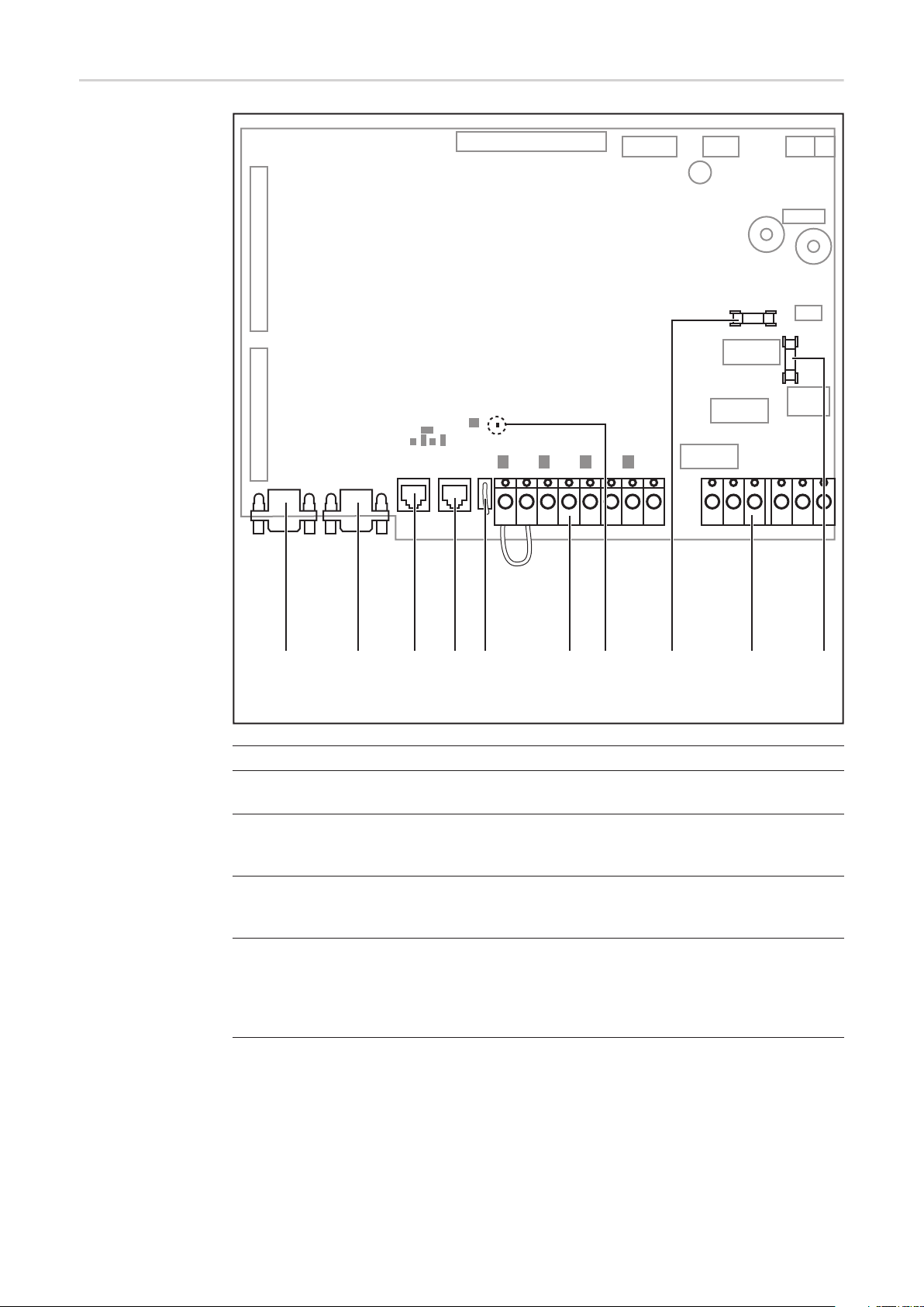
Connection compartment
EN
(1) (2) (3)(4) (5) (6) (7) (8) (9)
Item Description
(1) DC+ connections
(2) Openings for attaching the strain-relief clamps* for the DC+ cable
(3) Cable input opening with sliding cover and seal
(4) DC- connections
(5) Openings for attaching the strain-relief clamps* for the DC- cable
(6) Openings for attaching the strain-relief clamps* for the AC cable
(7) Grounding terminal for AC cable
(8) Mains connections L1, L2, L3 and N with connection cover
(9) AC power supply
* The strain-relief clamps and other installation and connection accessories are
part of the scope of supply of the inverter.
21
Page 24
Data communication area
(1) (2) (3) (4) (5) (6) (7) (10)(8) (9)
Item Description
(1)
(2)
for future use
(3) Solar Net IN connection socket
'Fronius Solar Net' input, for connecting to other DATCOM components (e.g. inverter, sensor box, etc.)
(4) Solar Net OUT connection socket
'Fronius Solar Net' output, for connecting to other DATCOM components (e.g. inverter, sensor box, etc.)
(5) VSR connection socket
for connecting an external measuring and monitoring relay
The contact must be potential-free.
Contact rating 24 V / 10 mA
22
Page 25

Item Description
(6) NO/alarm terminals
| S3 EXT 2 | 3 IN1 4 | 5 IN2 6 | 7 IN3 8 |
S3 - 2 EXT
for connecting an external NO contact, e.g. to isolate the device from the
grid voltage using an AC contactor;
connected using bracket when delivered.
EN
3 - 4 IN1
for connecting and evaluating a floating alarm contact
5 -6 IN2
for connecting and evaluating a floating alarm contact
7 - 8 IN3
for connecting and evaluating a floating alarm contact
The contacts must be potential-free.
Contact rating 24 V / 10 mA
Cable cross-section: 0.5 - 6 mm²
Tightening torque of terminals: 0.8 - 1.6 Nm
(7) 'Solar Net' LED
shows the current status of the Fronius Solar Net
(8) Fuse F1 for switched-mode power supply, 4 A slow-blow
23
Page 26
Item Description
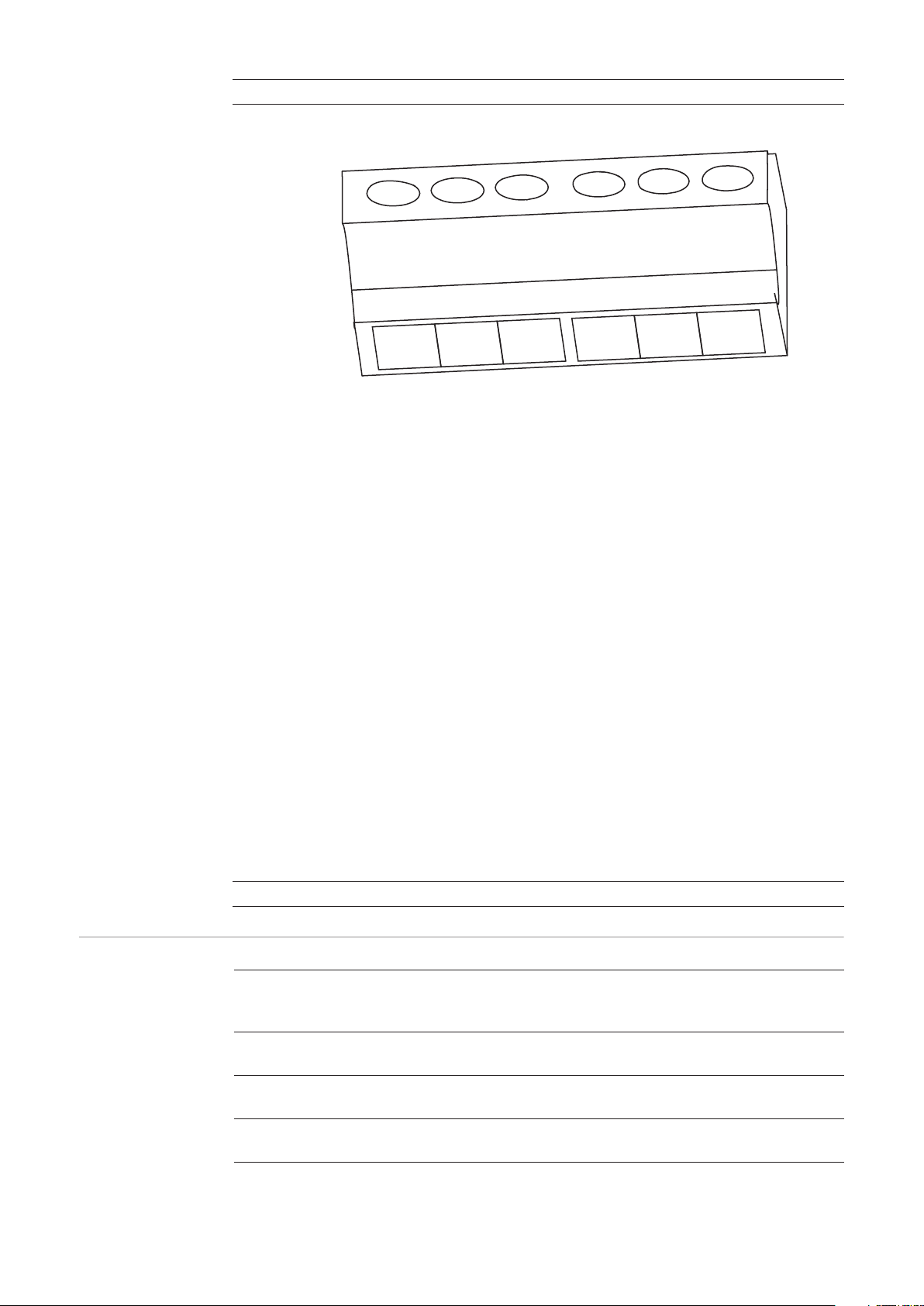
(9) Relay output terminals
| NC1 SC1 NO1 | NC2 SC2 NO2 |
NC1 NC for relay contact 1
SC1 Relay contact 1
NO1 NO for relay contact 1
NC2 NC for relay contact 2
SC2 Relay contact 2
NO2 NO for relay contact 2
Possible relay
contact functions
Cable cross-section: 0.5 - 6 mm²
Tightening torque of terminals: 0.8 - 1.6 Nm
Max. continuous current: 16 A
Switching load: 500 mW (10 V / 5 mA)
Switching capacity: 16 A / 250 V (AC1) and 16 A / 30 V (DC1)
The relay outputs are not protected.
Relay contacts can be assigned different functions in the Basic service menu. The
access code 22742 must be entered to access the Basic service menu:
- Press the 'Menu' key
- Select 'Setup' mode
- Press the unassigned 'Esc' button five times
- Enter the access code 22742
- Select the 'Switch contact 1' or 'Switch contact 2' parameter
- Set the desired relay contact function
(10) F2 fuse, 4 A slow-blow
Function Switch contact ac-
tivation criterion
1)
Switch contact deactivation criteri-
2)
on
Description
Off - Permanently OFF Function switched
off
On Permanently ON - Test function for NO/
alarm contact
AC Open AC contactor is open AC contactor is
closed
No contactor error
signal or AC grid
24
Page 27

Function Switch contact ac-
tivation criterion
1)
Fan On Cabinet fan in opera-
tion
> 40 °C max. internal tem-
perature >/= 40 °C
> 50 °C max. internal tem-
perature >/= 50 °C
Sig. Rel. NO/alarm contact
trips
Running Inverter feeding en-
ergy into the grid
Warning Defined warning sta-
tus codes
Error Defined error status
codes
Switch contact deactivation criteri-
2)
on
Cabinet fan not
working
max. internal temperature </= 30 °C
max. internal temperature </= 40 °C
Error confirmation at
the touch of a button
/ by Solar Net command
Inverter not feeding
energy into the grid
Error confirmation at
the touch of a button
/ by Solar Net command
Error confirmation at
the touch of a button
/ by Solar Net command
Description
EN
External ventilation /
air conditioning can
be activated
Status indicator / relay contact switches
Control of powered
non-return valve
NO/alarm contact
activation, when certain warning status
codes occur at a
specific frequency
according to the 'Error-Counter' Service
menu
NO/alarm contact
activation, when certain error status
codes occur at a
specific frequency
according to the 'Error-Counter' Service
menu
1)
Activation = the NC for the relay contact opens, the NO closes
2)
Deactivation = the NC for the relay contact closes, the NO opens
25
Page 28

Data communication and Solar Net
Solar Net and
data interface
Overcurrent and
undervoltage cutout
Fronius Solar Net was developed to make system add-ons flexible and capable of being
used in a wide variety of different applications. Fronius Solar Net is a data network that
enables more than one inverter to be linked up using system add-ons.
It is a bus system. A single cable is all that is required for one or more inverters to communicate with all the system add-ons.
Fronius Solar Net automatically recognises a wide variety of system add-ons.
In order to distinguish between several identical system add-ons, each one must be assigned a unique number.
Similarly, every inverter on the Fronius Solar Net must be assigned a unique number.
Refer to the section entitled 'The Setup-Menu‘ for instructions on how to assign a unique
number.
More detailed information on the individual system add-ons can be found in the relevant
operating instructions or on the internet at http://www.fronius.com.
More detailed information on cabling DATCOM components can be found at
http://www.fronius.com - Solar Electronics / Info & Support / Document downloads / Operating instructions / System monitoring / Fronius DATCOM cabling guide.
The data communications electronics have a cut-out function that interrupts the power supply in the Fronius Solar Net:
- in response to overcurrent, e.g. in the event of a short circuit
- in response to undervoltage
Description of the
'Fronius Solar
Net' LED
The overcurrent and undervoltage cut-out does not depend on the current flow direction. If
the Fronius Solar Net measures a current flow > 3 A or a voltage < 6.5 V, the power supply
in the Fronius Solar Net is interrupted.
The power supply is restored automatically.
The 'Fronius Solar Net' LED is on:
the power supply for data communication within the Fronius Solar Net is OK
The 'Fronius Solar Net' LED is off:
data communication error in the Fronius Solar Net
- Overcurrent (current flow > 3 A, e.g. resulting from a short circuit in the Fronius Solar
Net)
- Undervoltage (not a short circuit, voltage in Fronius Solar Net < 6.5 V, e.g. if there are
too many DATCOM components on the Fronius Solar Net and not enough electrical
power is available)
In this case, power for the DATCOM components must be supplied by connecting an
external power unit to one of the DATCOM components.
To detect the presence of an undervoltage, check some of the other DATCOM components as required.
The 'Fronius Solar Net' LED flashes briefly every 5 seconds:
following a shutdown as the result of an overcurrent or undervoltage, the inverter attempts
to restore the power supply to the Fronius Solar Net every 5 seconds while the fault persists.
26
Page 29

Once the fault is rectified, power to the Fronius Solar Net will be restored within 5 seconds.
Example Recording and archiving of inverter data using Fronius Datalogger Web, data output on ex-
ternal display:
EN
Fronius Agilo
Fronius IG Plus
Display
Fronius Datalogger Web
12VDC 1A
Class 2
12VDC
Output
Class 2
Input only
max. 42V AC/6A
US: Class 2 only
RS232
IN
OUT
LAN
IN
OUT
Fronius
Public Display
Box
IN
OUT
= terminating plug
PC / Laptop
= Fronius Com Card
Captions:
Fronius Solar Net data network with
- 1 Fronius Agilo
- 1 Fronius IG Plus with a 'Fronius Com Card'
- 1 Fronius Datalogger Web with LAN interface for connecting to a PC/laptop
- 1 Fronius Public Display Box
- 1 external display
Communication between the individual components themselves is handled by Fronius Solar Net.
27
Page 30

28
Page 31

Installation and commissioning
Page 32

Page 33

Choice of location
EN
General comments regarding
choice of location
Cabling into the
inverter
The IP 30 degree of protection of the inverter dictates that it be installed exclusively in enclosed spaces or containers.
The inverter must be completely covered by a building or structure in order to protect it from
rain, snow, wind-borne dust, fungal attack, radiation on cold nights, etc.
The building or structure must satisfy the requirements in terms of temperature, humidity
and air filtering. Condensation is not anticipated.
The following points must also be taken into account in the choice of location:
- the cabling into the inverter,
- the specified bending radii of the cables,
- adequate bearing capacity per m² of floor for the inverter weight of 834 kg.
IMPORTANT! The adequate bearing capacity of the floor must be ensured before introducing and setting up the inverter!
The AC cable, DC cable and the data communications cable, if required, can be fed into
the inverter-as follows:
a) b) c) Plan view
Criteria influencing choice of location
a) from below (e.g. via a cable duct or a false floor)
b) from the side through the base
c) from the rear through the base
Feeding the cabling through the base is only possible for cables with a cross-section of
max. 120 mm².
IMPORTANT! If AC cables, DC cables and data communication cables are fed together
into the inverter, ensure adequate insulation is provided between the AC/DC cables and
the data communication cables.
Place on a solid, even. level and fire-resistant surface only.
Max. ambient temperatures: -20 °C; +50 °C
Can be used at altitudes of up to 2000 m
31
Page 34

Maintain the following lateral clearances between the inverter and a wall:
450 mm
400 mm*
0 mm
250 mm**
* Wall - left side of inverter:
min. 400 mm (to permit the door to be opened fully and its catch to be latched)
min. 50 mm (to open the door 90°, door catch not latched)
** Wall - right side of inverter:
min. 250 mm (to permit the air inlet grille to be opened fully)
Two or more inverters can be placed side-by-side or back-to-back.
The clearance between the top of the inverter and the ceiling must be at least 450 mm in
order to prevent air from accumulating.
If the clearance is less than this, install an extractor.
The airflow within the inverter is from the front to the top (cold air taken in at the front, hot
air emitted out of the top).
If the inverter is installed in an enclosed space, then forced-air ventilation must be provided to ensure adequate heat dissipation.
Unsuitable locations
32
Do not install the inverter:
- in living areas
- in rooms where the device will be directly exposed to water
- in rooms subject to heavy accumulations of dust
- in rooms in which a heavy build-up of dust containing conductive particles (e.g. iron
chips) is likely
- in rooms containing caustic vapours, acids or salts
- in places where there is an increased risk of damage from farm animals (horses, cattle, sheep, pigs, etc.)
- in stables or adjoining areas
- in storage areas for hay, straw, chaff, animal feed, fertilisers, etc.
- in storage or processing areas for fruit, vegetables or winegrowing products
- in rooms used in the preparation of grain, green fodder or animal feeds
- in greenhouses
Page 35

Transport
Transport The inverter weighs approx. 850 kg and can be transported as follows:
- by its lifting eyes, e.g. using a crane or other suitable lifting gear and tackle
- by its forklift truck receptacle, e.g. using a forklift truck, lift truck or crane in conjunction
with pallet forks
- manually using the heavy-duty castors attached to the inverter
EN
Transporting by
its lifting eyes using a crane
WARNING! Falling equipment can cause serious or even fatal injury. When
transporting the inverter using a crane
- always use all four of the lifting eyes provided for this purpose,
- the length of the lifting tackle (chain, rope, strap, etc.) must be chosen so that
the angle between the lifting tackle and the horizontal is at least 60°.
min. 60°
Transporting by
crane using pallet
fork
WARNING! Falling equipment can cause serious or even fatal injury. When
transporting the inverter using a crane and pallet fork
- the pallet fork must have a headroom of at least 1900 mm
- always insert the pallet fork into the forklift truck receptacle
- always insert the pallet fork completely into the forklift truck receptacle
- secure the inverter to prevent it slipping off the pallet fork
Remove the front and rear cover from the base of the inverter before transporting it using
a pallet fork, forklift truck or lift truck.
33
Page 36

2
1
3
4
2x
Transporting by
forklift truck or lift
truck
WARNING! Equipment that falls or topples over can cause serious or even fatal
injury.
- always insert the fork into the forklift truck receptacle
- always insert the fork completely into the forklift truck receptacle
- secure the inverter to prevent it slipping off the fork or falling over
- avoid sudden changes in direction, braking or acceleration
Remove the front and rear cover from the base of the inverter before transporting it using
a pallet fork, forklift truck or lift truck.
2
1
3
4
2x
Manual transport There are four heavy-duty castors on the underside of the inverter.
If it is not possible to transport the inverter by crane or a forklift or lift truck, these heavyduty castors will enable someone to push it over a flat surface.
The heavy-duty castors are particularly suitable for positioning the inverter exactly and
compensating for any slight unevenness.
34
Page 37

Positioning the inverter
EN
Prerequisites
Positioning the
inverter
WARNING! Equipment that falls or topples over can cause serious or even fatal
injury.
- Place the inverter on a solid, level surface in such a way that it remains stable.
- Do not under any circumstances tip the inverter while it is being positioned.
Before positioning the inverter, clarify how the cables are going to be fed in.
If it is not going to be possible to feed any cables into the inverter once it has been positioned, all the AC, DC and data communication cables must, before the inverter is put in
place,
- be dimensioned accordingly,
- protrude at least 650 mm out of the floor.
CAUTION! Risk of cable damage as a result of shearing or bending.
if any cables are protruding out of the floor, use a crane or forklift truck to lift the
inverter over the cables and position the inverter in its desired location. Under no
circumstances attempt to position the inverter using the heavy-duty castors.
Once the inverter has been positioned and the cables have been fed into it, any fine positional adjustments can then be made using the heavy-duty castors.
IMPORTANT! Ensure that any covers which were removed previously are refitted before
the inverter is moved to its final position (e.g. fit the rear cover before positioning the inverter up against a wall).
Transport the inverter to its location
1
Fit any covers that will no longer be accessible once the inverter is in its final position
2
Move the inverter manually into its final position using the heavy-duty castors
3
CAUTION! An inadequate ground conductor connection can cause serious injury
or damage.
The screws on the air inlet grille and on the covers provide a suitable ground conductor connection for the housing; these screws must not under any circumstances be replaced by other screws that do not provide a reliable ground conductor
connection.
1
4
1
2
2
2
2
3
2
35
Page 38

2
5
4
1
3
2
3
6
7
6
5
Fixing the heavy-duty castors
+
-
(1) Castor
(2) Rubber stopper
-
x4
+
* Ways of accessing the heavy-duty
castors on the underside of the inverter
*
*
*
*
*
*
1
2
Counter-clockwise:
unscrew rubber stopper
Clockwise:
screw in rubber stopper
Notes regarding
the air supply and
the connection of
an exhaust duct
IMPORTANT! Secure all 4 of the inverter's heavy-duty castors. Unscrew the rubber stop-
per beyond the castor.
To prevent any subsequent distortion of the doors of the inverter, ensure that the inverter
is always absolutely level.
Any slight unevenness can be compensated for using the rubber stoppers.
The air supply to the inverter must be at least 1200 m³/h (approx. 20 m³/min).
When connecting an exhaust duct, the back pressure it causes must not exceed 150 Pa.
This results in a volumetric flow of about 15 m³/min.
36
Page 39

Connecting the inverter to the public grid (AC)
EN
Monitoring the
grid
Mains connections
IMPORTANT! To provide the best possible grid monitoring, the resistance in the leads to
the mains connections should be as low as possible.
Legend:
L1 Phase conductor
M10
PE
NOTE! Ensure that the grid neutral conductor is grounded.
L2 Phase conductor
L3 Phase conductor
N Neutral conductor
PE Ground conductor / grounding
Connecting aluminium cables
IMPORTANT! Only the following cables may be connected to V-type terminals:
- RE (round single-wire)
- RM (round multi-strand)
- SE (sector-shaped single-wire)
- SM (sector-shaped multi-strand)
- fine-core cables, in conjunction with ferrules only
Fine-core cables without ferrules may only be connected to the M10 threaded bolts of the
mains connections using a suitable M10 cable lug;
tightening torque = 18 Nm
Aluminium cables can be connected to the mains connections.
NOTE! When connecting aluminium cables:
- observe national and international guidelines regarding the connection of aluminium cables
- follow the instructions of the cable manufacturer
- check every year that the cables are securely attached in accordance with
the specified torque.
Max. cross-section of AC cables
The max. cross-section of the AC cables is 95 mm². The optimum bending radii inside the
inverter are derived from this cable cross-section.
37
Page 40

Safety
WARNING! An electric shock can be fatal. Danger due to grid voltage and DC
voltage from solar modules.
- Make sure that both the AC side and the DC side of the inverter are de-energised before making any connections.
- Only an authorised electrical engineer is permitted to connect this equipment
to the public grid.
CAUTION! Risk of damage to the inverter as the result of incorrectly tightened cable connections. Incorrectly tightened cable connections can cause heat damage
to the inverter that may result in a fire. When connecting AC and DC cables, ensure that all the cables are tightened to the inverter terminals with the specified
torque.
Connecting the
inverter to the
public grid
NOTE! Ensure that the phases are connected in the right order: L1, L2, L3, N and
PE.
After connecting the phases, check the rotary field of the grid using a rotary field
measuring device. The inverter is designed for a clockwise rotary field.
IMPORTANT!
Minimum cable cross section for the ground conductor PE:
10 mm² für Copper wire
16 mm² für Aluminium wire
1
1
AC
1
OFF
38
2
2
- Open the connection covers for the
mains connections
Page 41

3
3
- Feed the AC cable into the inverter, observing the bending radii specified by
the cable manufacturer
EN
- Strip sheath from AC cable
- Strip at least 20 mm of wire from phase
conductor L1 - L3, neutral conductor N
and ground conductor PE
- Align phase conductors L1 - L3 and
neutral conductor N with the mains
connections according to the phase
- Align the ground conductor PE with the
grounding terminal
- Push the AC terminal over the phase
conductor, the neutral conductor and
the ground conductor
4
4
- Push the AC terminal up and over the
mains connection and the bare end of
the cable
- Tighten the AC terminal:
5 mm Allen key
3
Tightening torque = 12 Nm
3
2
1
4x
1
L1
L2
L3
N
5
5
- Place the insulation caps onto the
mains connections
- Repeat the process for phase conductors L2 and L3 and the neutral conductor N
- Close the connection covers for the
mains connections
39
Page 42

6
6
- Push the PE terminal up and over the
grounding terminal and the bare end of
the cable
- Tighten the PE terminal:
5 mm Allen key
Tightening torque = 12 Nm
7
7
- Place the AC cable in the clamp of the
strain-relief device
- Attach the clamps of the strain-relief
device to the rail
- Secure the AC cable with the clamps of
the strain-relief device
NOTE! Different openings are available on the rail for attaching the clamps of the
strain-relief device, depending on the cable routing.
e.g.:
A
C
B
A cable routed at an angle from the
bottom right - attach the clamp for
the strain-relief device to positions
3 and 4
Connecting AC
cables with a cable lug
40
B cable routed at an angle from the
1
2
4
3
6
5
bottom left - attach the clamp for the
strain-relief device to positions 1
and 2
C vertical cable routing - attach the
clamp for the strain-relief device to
positions 5 and 6
Alternatively, an AC cable with a cable lug can be connected to the M10 threaded bolts on
the mains connections in order to connect the AC cables to the V-type terminals.
Page 43

NOTE! Ensure that the phases are connected in the right order: L1, L2, L3, N and
PE.
After connecting the phases, check the rotary field of the grid using a rotary field
measuring device. The inverter is designed for a clockwise rotary field.
EN
Maximum fuse
rating on alternating current side
4x
L1
L2
L3
N
+
PE
M10
1
2
3
18 Nm
4
9
8
7
6
5
M10
Inverter Phases Nominal output Fuse protection
Fronius Agilo 75.0-3 3 100 kVA 3 x 200 A
Fronius Agilo 100.0-3 3 100 kVA 3 x 200 A
Connecting an
external AC supply for the inverter
Procedure for connecting an external AC supply for the inverter (e.g. to provide an external
supply to controllers or fans):
1 2
1
N
7
5
3
1
2
N
6
2
5
4
*
4
6
2
8
3
1
LN
* If present, connect ground conductor to grounding terminal 9
41
Page 44

Fitting and connecting optional overvoltage protection
General Standard type II overvoltage protection can be fitted in the inverter as an option:
- for the DC side,
- for the AC side,
- for the external AC supply of the inverter.
DIN rails and passage openings to the AC and DC terminals for the cables are provided in
the inverter for fitting overvoltage protection.
The existing remote contacts on the overvoltage protection can be connected to the NO/
alarm contact terminals in the data communication area. In the event of a fault, the incoming signals can then be evaluated and shown on the display.
Overvoltage protection is not included in the scope of supply of the inverter. The engineer
is responsible for the correct selection of the relevant overvoltage protection so as to comply with national and international regulations.
Safety
Fitting and connecting overvoltage protection on
the DC side
WARNING! Work that is carried out incorrectly can cause serious injury and dam-
age. Overvoltage protection must only ever be installed and connected by a qualified electrical installation engineer!
Follow the safety rules!
Make sure that both the AC side and the DC side of the inverter are de-energised
before carrying out any installation or connection work.
NOTE! Installing a Type I overvoltage protection device in the inverter is prohibited.
IMPORTANT!
- Provide a separate grounding terminal for each overvoltage protection device
- Make sure that the cables have adequate insulation resistance.
Fit overvoltage protection to the DIN rail on the DC side according to the manufactur-
1
er's instructions
Fit a grounding terminal to the DIN rail on the DC side
2
Remove the 2 blank screw joints on the DC side
3
Insert 2 M20 screw joints from the inverter's accessories kit into the openings and se-
4
cure them with the hexagonal nuts of the blank screw joint
Prepare the cable:
5
- Strip the cable on the overvoltage protection side
- Fit the M10 cable lug on the DC connection side
42
Max. cable cross-section must comply with the instructions of the overvoltage
protection manufacturer.
Open the M20 screw joints
6
Feed the cable through
7
Connect the cable to the overvoltage protection device according to the manufactur-
8
er's instructions
Page 45

Use the M10 hexagonal nut and the washer to connect the cable with the correct po-
9
larity at the central M10 threaded bolt of the relevant DC connection
Close the M20 screw joints
10
Connect the overvoltage protection to the grounding terminal
11
If available, connect the remote contacts of the overvoltage protection device with two
12
cables to the NO/alarm contact terminals in the data communication area
EN
Fitting and connecting overvoltage protection on
the AC side
IMPORTANT!
- Provide a separate grounding terminal for each overvoltage protection device
- Make sure that the cables have adequate insulation resistance.
Fit overvoltage protection to the DIN rail on the AC side according to the manufactur-
1
er's instructions
Fit a grounding terminal to the DIN rail on the AC side
2
Remove 3-4 blank screw joints on the AC side, depending on the overvoltage protec-
3
tion
Insert 3-4 M20 screw joints from the inverter's accessories kit into the openings and
4
secure them with the hexagonal nuts of the blank screw joint
Prepare the cable:
5
- Strip the cable on the overvoltage protection side
- Fit the M10 cable lug on the AC connection side
Max. cable cross-section must comply with the instructions of the overvoltage
protection manufacturer.
Open the M20 screw joints
6
Feed the cable through
7
Connect the cable to the overvoltage protection device according to the manufactur-
8
er's instructions
Connect the cable to the upper part of the relevant AC connection in the correct phase
9
sequence
Tightening torque = 18 Nm
Close the M20 screw joints
10
Connect the overvoltage protection to the grounding terminal
11
If available, connect the remote contacts of the overvoltage protection device with two
12
cables to the NO/alarm contact terminals in the data communication area
Fitting and connecting overvoltage protection for
the AC- supply
IMPORTANT!
- Provide a separate grounding terminal for each overvoltage protection device
- Make sure that the cables have adequate insulation resistance.
Fit overvoltage protection to the DIN rail on the AC side according to the manufactur-
1
er's instructions
Fit a grounding terminal to the DIN rail
2
Strip the cable on both sides
3
Max. cable cross-section must comply with the instructions of the overvoltage protection manufacturer.
Connect cables L1 and N on the overvoltage protection device according to the man-
4
ufacturer's instructions
43
Page 46

Run the cable to the 2-pin automatic circuit breaker to safeguard the AC power supply
5
Connect cables L1 and N on the automatic circuit breaker in the correct phase se-
6
quence
Connect the overvoltage protection to the grounding terminal
7
If available, connect the remote contacts of the overvoltage protection device with two
8
cables to the NO/alarm contact terminals in the data communication area
Bind the cable with cable ties if necessary
9
44
Page 47

Connecting the DC cable to the inverter
EN
General comments regarding
solar modules
DC connections
To enable suitable solar modules to be chosen and to use the inverter as efficiently as possible, it is important to bear the following points in mind:
- If insolation is constant and the temperature is falling, the open circuit voltage of the
solar modules will increase. The open circuit voltage must not exceed 950 V.
If the open circuit voltage exceeds 950 V, the inverter will be destroyed and no warranty claims will be entertained.
- More exact values for dimensioning the solar modules can be provided by suitable calculation programs, like the Fronius Solar.configurator (which can be downloaded from
www.fronius.com).
NOTE! Before connecting the solar modules, check:
- that the voltage specified by the manufacturer corresponds to the actual
measured voltage.
- whether the solar modules need to be grounded.
M10 M10 M10 M10
+
30 mm
DC+ DC-
Connecting aluminium cables
IMPORTANT! Only the following cables may be connected to V-type terminals:
- RE (round single-wire)
- RM (round multi-strand)
- SE (sector-shaped single-wire)
- SM (sector-shaped multi-strand)
- fine-core cables, in conjunction with ferrules only
Fine-core cables without ferrules may only be connected to the M10 threaded bolts of the
DC connections using a suitable M10 cable lug;
tightening torque = 30 Nm
Aluminium cables can also be connected to the DC connections.
NOTE! When connecting aluminium cables:
- observe national and international guidelines regarding the connection of aluminium cables
- follow the instructions of the cable manufacturer
- Once a year, make sure that the cables are securely connected according to
the specified torque.
Max. cross-section of DC cables
The DC connections on the inverter are designed for cables with a cross-section of max.
240 mm².
With this maximum cross-section, 2 cables can be connected to each pole.
45
Page 48

Safety
WARNING! An electric shock can be fatal. Danger due to grid voltage and DC
voltage from solar modules that are exposed to light.
- Make sure that both the AC side and the DC side of the inverter are de-energised before carrying out any connection work.
- Only an authorised electrical engineer is permitted to connect this equipment
to the public grid.
CAUTION! Risk of damage to the inverter as the result of incorrectly tightened
terminals. Incorrectly tightened terminals can cause heat damage to the inverter
that may result in a fire. When connecting AC and DC cables, ensure that all the
terminals are tightened to the specified torque.
Connecting DC
cables
Remove contact protectors
1
Feed the DC cable into the inverter, observing the bending radii specified by the cable
2
manufacturer
Strip at least 25 mm of insulation from the DC cable
3
Align the DC cable with the DC connections
4
3
5
DC+ DC-
1
- Push the DC terminal over the
DC cable
- Push the DC terminal up and over the
DC connection and the bare end of the
cable
1
3
2
4
4
6
- Tighten the DC terminal:
6 mm Allen key
Tightening torque = 25 Nm
- Repeat this process for every DC cable
- Place the DC cable in the clamp of the
strain-relief device
- Attach the clamp of the strain-relief device to the rail
- Secure the DC cable with the clamp of
the strain-relief device
- Repeat this process for every DC cable
46
Fit the contact protectors
7
NOTE! Different openings are available on the rail for attaching the clamps of the
strain-relief device, depending on the cable routing.
Page 49

e.g.:
Connecting DC
cables with a cable lug
AB
C
A cable routed at an angle from the
bottom right - attach the clamp for
the strain-relief device to positions
1 and 2
B cable routed at an angle from the
1
4
6
5
3
2
bottom left - attach the clamp for the
strain-relief device to positions 3
and 4
C vertical cable routing - attach the
clamp for the strain-relief device to
positions 5 and 6
Alternatively, a DC cable with a cable lug can be connected to the M10 threaded bolts on
the DC connections in order to connect the DC cables to the V-type terminals.
NOTE! Ensure the polarity is correct when connecting the DC cables.
EN
Fuse protection
against polarity
reversal of DC cables
2x
DC+
2x
DC-
M10
2
3
4
5
1
18 Nm
The inverter is fitted with a fuse to protect against any polarity reversal of the DC cables.
The fuse will blow if the inverter is activated with the polarity of the DC cables reversed.
Status code 307 "DC low" is shown on the display, even in the event of sufficient levels of
insolation.
Should this occur, the reverse polarity protection fuse must be replaced as described under
"Replacing fuses" in the "Troubleshooting and maintenance" section.
47
Page 50

Grounding the solar modules in the inverter
General Some manufacturers of solar modules stipulate that the module must be grounded.
Inside the inverter is a means for grounding
solar modules to the negative pole via a fuse.
Locking ring for solar module grounding on the negative pole
Grounding the
solar module to
the negative pole
via a fuse
Grounding the solar module to the negative pole via a fuse
(1) Solar module
(2) Inverter
(1)
DC+
DC-
(3)
(2)
=~=
L1
L2
L3
N
(3) Fuse
~
PE
Fronius recommends the following fuse when grounding the solar module to the negative
pole:
nominal current rating 3 A / 1000 V, fuse dimensions 10 x 38 mm
IMPORTANT! Fuses for grounding the solar module are not part of the scope of supply of
the inverter. If the manufacturer of the solar module stipulates that grounding is required,
an appropriate fuse must be ordered separately
48
WARNING! An electric shock can be fatal. Danger of electric shock if the solar
module is not grounded or is not grounded properly.
To comply with IEC 62109-2, any grounding required by the manufacturer of the
solar module within the inverter must only be carried out via the specified fuse.
Page 51

Safety
WARNING! An electric shock can be fatal. Danger due to DC voltage from solar
modules that are exposed to light. The inverter's insulation monitoring is deactivated when the solar modules are grounded.
- Ensure that grounded solar modules are designed so that they are isolated
according to Protection Class II
- Place the relevant safety sticker in a clearly visible place on the photovoltaic
system
- Configure the inverter so that a warning message is displayed if the fuse
trips.
Warning sticker for solar module grounding
IMPORTANT! The warning sticker and
the fuse for grounding the solar module
Warnung!
Ein elektrischer Schlag kann tödlich sein.
Gefahr durch DC-Spannung von den
Solarmodulen.
Die Isolationsüberwachung des Wechselrichters ist deaktiviert. Die Solarmodule
sind geerdet.
VorArbeiten an der Photovoltaik-Anlage
AC- und DC-Seite spannungsfrei schalten.
Warnung!
Ein elektrischer Schlag kann tödlich
sein. Gefahr durch DC-Spannung von
den Solarmodulen.
Die Isolationsüberwachung des
Wechselrichters ist deaktiviert. Die
Solarmodule sind geerdet.
VorArbeiten an der Photovoltaik-kAnlageAC- und DC-Seite spannungsfrei schalten.
Warnung!
Ein elektrischer Schlag kann tödlich
sein. Gefahr durch DC-Spannung von
den Solarmodulen.
Die Isolationsüberwachung des
Wechselrichters ist deaktiviert. Die
Solarmodule sind geerdet.
VorArbeiten an der Photovoltaik-kAnlageAC- und DC-Seite spannungsfrei schalten.
Warnung!
Ein elektrischer Schlag kann tödlich sein.
Gefahr durch DC-Spannung von den
Solarmodulen.
Die Isolationsüberwachung des Wechselrichters ist deaktiviert. Die Solarmodule
sind geerdet.
VorArbeiten an der Photovoltaik-Anlage
AC- und DC-Seite spannungsfrei schalten.
Warnung!
Ein elektrischer Schlag kann tödlich
sein. Gefahr durch DC-Spannung von
den Solarmodulen.
Die Isolationsüberwachung des
Wechselrichters ist deaktiviert. Die
Solarmodule sind geerdet.
VorArbeiten an der Photovoltaik-kAnlageAC- und DC-Seite spannungsfrei schalten.
are not part of the scope of supply of the
inverter and must be ordered separately.
EN
Configuring the
inverter for
grounded solar
modules
Grounding the
solar module on
the negative pole:
inserting a fuse
The inverter's insulation monitoring must be deactivated when the solar modules are
grounded. At the second level of the Setup menu, the inverter must be configured so that
when the grounding fuse trips, an error message is displayed or the inverter is switched off
(according to the country setup).
Access code 22742 must be entered in order to access the 2nd level of the Setup menu.
WARNING! An electric shock can be fatal. Danger due to DC voltage from solar
modules that are exposed to light.
The DC main switch is only to be used to de-energise the power stage set.
Grounding of the solar module on the negative pole remains in effect, even when
the DC main switch is switched off. Do not under any circumstances touch DC+
or DC-.
49
Page 52

1 2
1
2
1
1
2
Inserting the fuse grounds the solar modules on the negative pole.
50
Page 53

Closing the inverter
EN
Closing the inverter
CAUTION! An inadequate ground conductor connection can cause serious injury
or damage.
The screws on the air inlet grille and on the covers provide a suitable ground conductor connection for the housing; these screws must not under any circumstances be replaced by other screws that do not provide a reliable ground conductor
connection.
Check that all covers and contact protection devices are fitted;
1
fit any covers and contact protection devices that are missing
3
2
1
2
3
4
5
6
7
Tightening torque = 3 Nm
NOTE! To avoid damaging the DC main switch, only close the door of the inverter
once the switch itself is switched to the "OFF" position.
1
3
2
1
1
1
1
1
Tightening torque = 3 Nm
3
51
Page 54

2
4
Tightening torque = 3 Nm
1
3
2
4
x2
5
52
Page 55

Using for the first time
EN
Factory configuration
Using for the first
time
The inverter is preconfigured in the factory. The language and the time must be set when
the inverter is used for the first time.
Refer to the section in this manual entitled 'The Setup Menu' for the individual configuration
options.
After connecting the DC cable to the inverter and the inverter to the grid (AC):
Insert covers and contact protection
1
Close and secure air inlet grilles
2
Close door
3
Turn the DC main switch to the - 1 - position
4
If the solar modules are producing enough voltage, the inverter will enter the startup phase.
The inverter is about to start up automatically.
Once the inverter has completed its automatic startup, the operating state LED will show
steady green.
Provided that energy continues to be fed into the grid, the operating state LED will remain
steady green to confirm that the inverter is functioning correctly.
A window then appears for setting the language:
The time and the date must then be set:
Use the 'Up' and 'Down' keys to select
5
the desired language
Press the 'Enter' key to set the lan-
6
guage
The time is displayed
(HH:MM:SS, 24-hour format),
the hours field starts flashing.
Use the 'Up' and 'Down' keys to select
7
a value for the hour
Press the 'Enter' key
8
The minutes field starts flashing.
Repeats steps 7 and 8 for the minutes
9
and seconds until...
53
Page 56

the set time starts flashing.
Press the 'Enter' key
10
The time is applied and the date now appears (DD.MM.YYYY), the day field starts
flashing.
Use the 'Up' and 'Down' keys to select
11
a value for the day
Press the 'Enter' key
12
The month field starts flashing.
Repeat steps 11 and 12 for the month
13
and the last 2 digits of the year until ...
Configuring the
inverter for existing solar module
grounding
the set date starts flashing.
Press the 'Enter' key
14
If setting of the language and the time are skipped by pressing the Back key and no settings are made during the setup, these two prompts appear again the next time the inverter
is started.
NOTE! If the solar module is already grounded on the negative pole, the appropriate grounding method must be set in the 'Basic Service Menu' when the inverter is switched on.
The access code 22742 must be entered in order to access the 'Basic Service
Menu'.
Confirm any status codes that are displayed by pressing 'Enter'
1
Press the 'Menu' key
2
Press the unassigned 'Menu / Esc' key
3
5 times
54
Enter the access code 22742
4
The inverter is now in the 'Basic Service Menu' and the first parameter 'DC operating mode'
is displayed.
Page 57

Grounding Mode
Use the 'Up' and 'Down' keys to select
5
the 'Grounding Mode' parameter
Press the 'Enter' key
6
'Grounding method' is displayed.
Press the 'Enter' key
7
The currently selected grounding method
is displayed.
Off = un-grounded system (no solar module grounding)
Factory setting
Use the 'up' or 'down' buttons to se-
8
lect the 'Negative' grounding method
EN
Grounding Mode
Negative = solar module grounded on the
negative pole:
Press the 'Enter' key
9
The 'Negative' grounding method is applied, 'Grounding method' and 'Grounding
monitoring' are displayed.
To quit the 'Basic Service Menu',
10
press the 'Esc' key twice
55
Page 58

56
Page 59

Operation
Page 60

Page 61

Controls and indicators
Controls and indicators
Item Description
(1) Display
for displaying values, settings and menus
EN
(1)
(2)
(3)
(4)
(5) (6) (7) (8)
Monitoring and status LEDs
(2) General status LED (red)
lights when there is a status code on the display
(3) Startup LED (orange)
for displaying whether the inverter is in its startup phase or is on standby
(4) Operating state LED (green)
for displaying the operating state
Function keys - allocated different functions depending on the selection:
(5) 'Left/up' key
for navigating to the left and up
(6) 'Down/right' key
for navigating down and to the right
(7) 'Menu/Esc' key
for switching to the menu level
for quitting the Setup menu
(8) 'Enter' key
for confirming a selection
Display Power for the display comes from the mains voltage. The display is therefore available per-
manently.
IMPORTANT! The display on the inverter is not a calibrated measuring device. A slight inaccuracy of a few percent from the energy meter used by the energy supply company is
intrinsic to the system. A calibrated meter will be needed to calculate the bills for the energy
supply company.
59
Page 62

Display areas in display mode
Display modes
Parameter explanation
Display of values and units as well as
status codes
Function key assignment
Inverter no. | Storage sym. (**)
Symbols showing
function key allocation
(*)
1
Display modes
Preceding menu items
Currently selected menu item
Next menu items
Function key assignment
Display areas in setup mode
(*) Scroll bar
(**) INV no. = Inverter DATCOM number,
Save symbol - appears briefly while the selected values are being saved
The following symbols are displayed to indicate the function key assignments:
Navigate: left
Navigate: up
Increase value
Navigate: right
Navigate: down
Reduce value
Menu / Back
Enter
60
Page 63

Monitoring and
status LEDs
(1) General status LED (red)
(2) Startup LED (orange)
(3) Operating state LED (green)
(1)
(2)
(3)
LED Colour Activity Explanation
(1) red lights up General status: the relevant status code is
shown on the display
Interruption while feeding energy into the grid
While error handling (the inverter waits for an acknowledgement or for an error to be rectified)
(2) orange lights up The inverter will enter its automatic startup or
self-test phase as soon after sunrise as the solar
modules are delivering sufficient power
The inverter has been switched to standby mode
in the setup menu = grid power feed operation
switched off manually
The inverter software is being updated
(3) green lights up The LED lights up after the automatic startup
phase of the inverter, provided energy is being
fed into the grid.
The photovoltaic system is working properly.
EN
A list of the relevant status codes, and causes and remedies can be found in the 'Status
diagnosis and repair' section under 'Maintenance and service'.
61
Page 64

Startup phase and feeding energy into the grid
Startup phase Once it has been switched on automatically, the inverter carries out the following tests and
checks:
a) Self-test of all important inverter components - the inverter runs through a virtual
checklist
b) Synchronisation with the grid
c) Startup test
Before the inverter starts feeding energy into the grid, the grid conditions according to
national regulations are tested.
Depending on the country-specific regulations, the startup test can last just a few seconds or take several minutes.
During the startup phase:
- the operating state LED shows orange,
- the string 'warte...' (wait...) and the currently tested component are displayed, e.g.:
Feeding energy
into the grid
- Once the tests have been completed the inverter starts feeding energy into the grid
- The display shows the current energy level that is being fed into the grid, e.g.:
- The operating state LED shows green, the inverter is working.
62
Page 65

Navigation at the menu level
EN
Activate display
backlighting
Automatic deactivation of display
backlighting /
change to display
mode 'NOW'
Open menu level
Press any key
1
The display backlighting is activated.
The option remains in the setup menu to set the display backlighting so that it is on all
the time or off all the time.
If no key is pressed for 2 minutes,
- the display backlighting switches off automatically and the inverter switches to display
mode 'NOW' (assuming the display backlighting is set to automatic).
- The switchover to the 'NOW' display mode can happen from anywhere within the display modes or the Setup menu, with the exception of the 'Standby' menu item.
- The amount of energy currently fed in is displayed.
Press the 'Menu' key
1
'Menu' will appear on the display
The inverter is now at the menu level.
From the menu level
- the required display mode can be selected
- the Setup menu can be accessed
63
Page 66

The display modes
The display
modes
Choosing a display mode
The following display modes are available on the inverter:
Display mode 'NOW' ...... Displays real-time values
Display mode 'TODAY' ...... Displays values for energy fed into the grid today
Display mode 'YEAR' ...... Displays values for energy fed into the grid during
the current calendar year
Display mode 'TOTAL' ...... Displays values for energy fed into the grid since
the inverter was originally commissioned.
Open menu level
1
Use the 'left' and 'right' keys to select
2
the required display mode
Overview of display values
Press the 'Enter' key
3
The first value of the selected display
mode is displayed.
Display mode Unit Display value
'NOW' W Energy supplied
Day characteristic
V Three-phase AC grid voltage
A Three-phase AC output current
Hz AC grid frequency
V PV array voltage
A PV array current
°C Ambient temperature
rpm Fan speed
64
Page 67

Display mode Unit Display value
'TODAY'
'YEAR'
HH:MM
DD.MM
SS
YY
kWh / MWh Energy Supplied
Time
Date
Day characteristic ('TODAY')
'TOTAL' Currency Yield
g / kg CO2 saving
W Max. output power
V Max. three-phase AC grid voltage
V Max. PV array voltage
HH:MM Operating hours
EN
65
Page 68

Values in display mode 'NOW'
Choosing a display mode
Values in display
mode 'NOW'
First value in display mode 'NOW'
NOW
Choose display mode 'NOW'
1
The first value in display mode 'NOW' appears
Scroll to the next display value using
2
the 'Down' key
Scroll back up using the 'Up' key
AC Output Power
Power (in watts) currently being fed into the grid
Press the 'Enter' key to display the day characteristic.
Day characteristic
Displays a plot showing the power output during
the day. The time axis is scaled automatically.
TODAY
Press the 'Back' key to remove the display
AC Grid Voltage
Phase voltage
(Volt)
Press the 'Enter' key to display the string voltage.
String Voltage
displays the string voltage of each phase.
Press the 'Back' key to remove the display
AC Output Current
Phase current currently being fed into grid
(Ampere)
66
Page 69

AC Grid Frequency
(Hertz)
PV Array Voltage
Voltage currently present on the solar modules
(Volt)
PV Array Current
Current that is being supplied at present by the solar modules (Ampere)
Ambient Temperature
Temperature of the air sucked in to cool the inverter
(°C)
EN
Fan Speed
(rpm)
Time
If the time is changed on an inverter or a system
add-on, it will also be changed in any other devices that are connected via Fronius Solar Net.
Date
If the date is changed on an inverter or a system
add-on, it will also be changed in any other devices that are connected via Fronius Solar Net.
67
Page 70

Values in display modes 'TODAY / YEAR / TOTAL'
Choose display
mode 'TODAY /
YEAR / TOTAL'
First value in display mode 'TODAY'
First value in display mode 'YEAR'
Choose display mode 'TODAY' or
1
display mode 'YEAR' or
display mode 'TOTAL'
The first value in the selected display
mode appears.
Scroll to the next display value using
2
the 'Down' key
Scroll back up using the 'Up' key
Values in display
modes 'TODAY /
YEAR / TOTAL'
First value in display mode 'TOTAL'
Energy Supplied
Energy fed into the grid during the period in question (kWh / MWh)
Press the 'Enter' key to display the day characteristic (only in display mode 'TODAY')
Day characteristic
Displays a plot showing the power output during
NOW
TODAY
There may be discrepancies with values displayed on other measuring instruments because of differences in measuring methods. As far as adding up the energy fed in is concerned, the only binding display values are those produced by the calibrated measuring
device provided by the electricity supply company.
the day. The time axis is scaled automatically.
Press the 'Back' key to remove the display
68
Page 71

Yield
Amount of money earned during the period in
question (currency can be selected in the Setup
menu)
Like the energy supplied figure, the yield figure may also exhibit discrepancies with other
measured values.
The 'Setup Menu' section explains how to select a currency and charge rate. The factory
setting depends on the respective country setup.
CO2 Savings
Amount by which CO2 emissions were reduced
during the period in question (g / kg)
The value for CO2 savings depends on the power station facilities and corresponds to the
CO2 emissions that would be released when generating the same amount of energy.
The factory setting is 0.59 kg / kWh (source: DGS – Deutsche Gesellschaft für Sonnenenergie e.V. (German Society for Solar Energy)
Max. Output Power
Largest amount of power (W) fed into the gird during the period in question
EN
Max. AC Grid Voltage
Highest AC grid voltage (V) measured during the
period in question
Max. PV Array Voltage
Highest PV array voltage (V) measured during the
period in question
69
Page 72

Operating Hours
Length of time the inverter has been working
(HH:MM).
Although the inverter does not operate during the night, the data required for the Sensor
Box option is logged and stored 24 hours a day.
IMPORTANT! A prerequisite for the correct display of day and year values is that the time
is set correctly.
70
Page 73

The Setup menu
Initial setting After completing comissioning the inverter is pre-configured depending on the country set-
up.
The SETUP menu item allows the initial settings of the inverter to be changed easily to
bring it in line, as closely as possible, with the preferences and requirements of the user.
EN
Accessing the
setup menu
Move up and
down the menu
items
'SETUP' menu level selected
'Standby' menu item
Switch to the menu level
1
(press the 'Menu' key)
Select 'Setup' mode using the 'Left' or
2
'Right' keys
Press the 'Enter' key
3
The first menu item in the Setup menu,
'Standby', is shown.
Example: 'Standby' menu item Example: 'Contrast' menu item
Accessing the setup menu
1
Use 'Up' and 'Down' keys to move between the available menu items
2
71
Page 74

Menu items in the Set-up menu
Standby Manual activation / deactivation of Standby mode
- The power electronics are switched off in standby mode. No energy is fed into the grid.
- The Startup LED will show steady orange.
- In Standby mode, no other menu item in the Setup menu can be accessed or adjusted.
- The automatic switchover into the 'NOW' display mode after 2 minutes of keyboard inactivity does not occur.
- Standby mode can only be terminated manually by pressing the 'Enter' key.
- Feeding energy into the grid can be resumed at any time (deactivate 'Standby').
Switching off Standby mode (manually switching off feeding energy into the grid):
Select the 'Standby' menu item
1
Press the 'Enter' key
2
'STANDBY' and 'ENTER' appear alternately on the display.
Standby mode is now active.
The Startup LED shows steady orange.
Resuming feeding energy into the grid:
'STANDBY' and 'ENTER' appear alternately on the display when in Standby mode.
Press the 'Enter' key to resume feeding energy into the grid
1
The 'Standby' menu item is displayed.
At the same time, the inverter enters the startup phase.
The operating state LED shows steady green when feeding energy into the grid has been
resumed.
Contrast Adjusts contrast on the display.
Unit -
Setting range 0 - 10
Factory setting 5
Since the contrast is temperature-dependent, when the ambient conditions change it may
be necessary to adjust the 'Contrast' menu item.
Backlighting Initial setting for display backlighting
72
Unit -
Setting range AUTO / ON / OFF
Factory setting AUTO
AUTO: Display backlighting is activated by pressing any key. If no key
is pressed for 2 minutes, the display backlighting will go off
again.
Page 75

ON: The display backlighting remains permanently on when the in-
verter is switched on.
OFF: The display backlighting is permanently switched off.
IMPORTANT! The 'Backlight' menu item only relates to the backlighting of the display and
the keys.
Language Setting the display language
Unit -
Display area German, English, French, Dutch, Italian, Spanish, Czech, Slo-
vak
Factory setting (depends on country setup)
Currency Sets the currency and charge rate for the energy fed into the grid
Unit -
Display area Currency/ feed-in tariff
Factory setting (depends on country setup)
EN
CO2 factor Setting the CO2 reduction factor
Unit kg/kWh
Setting range 00.01 - 99.99
Factory setting 0.59 kg/kWh
Yield Setting
- of an OFFSET value for the total energy display
- of a measuring offset factor for the day, year and total energy display
Setting range Meter deviation / meter unit of measurement / meter calibration
Meter deviation
Input of a value for the fed-in energy that will be added to the energy currently fed in (e.g.
carry-over value when replacing an inverter)
Unit Wh
Setting range Five digits
Factory setting 0
Meter unit of measurement
Input of a unit (k..., M...)
Unit -
73
Page 76

Setting range k / M
Factory setting -
Meter calibration
Input of a correction value to ensure that the value shown on the inverter display corresponds with the calibrated display on the electricity meter
Unit %
Setting range -5.0 - +5.0
Factory setting 0
DATCOM Checking data communications, entering the inverter number, protocol settings
Setting range Status / inverter number / protocol type
Status
Indicates data communication is taking place via a Fronius Solar Net or that a data communications error has occurred
Inverter number
Sets the number (= address) of the inverter in a system with several solar inverters
Unit -
Setting range 00 - 99 (00 = 100th inverter)
Factory setting 01
IMPORTANT! If a number of inverters are linked together in a data communications system, assign a unique address to each one.
Protocol type
Specifies the communications protocol to be used to transfer the data:
Unit -
Setting range Solar Net / Interface
Factory setting Solar Net
Device Info For displaying the settings that will be of relevance to an energy supply company. The val-
ues shown will depend on the country setup or the device-specific settings of the inverter.
Display area General / MPP Tracker / Grid Monitoring / Voltage Limits / Fre-
quency Limits / P AC Reduction
74
General:
Setup Country setup
Version Version of country setup
Group Group for updating the inverter software
MPP Tracker:
Page 77

DC Mode DC mode
FIX Voltage value in V for fixed voltage operation
User Voltage value in V for MPP User operation
Grid Monitoring:
GMTi Start-up time of inverter in s
GMTr Reconnection time in s following a grid fault
ULL Mean grid voltage over 10 minutes in V.
LL Trip Trip time for long-term voltage monitoring
Voltage Limits:
UIL max Upper inner grid voltage in V
UIL min Lower inner grid voltage in V
UOL max Upper outer grid voltage limit value in V
UOL min Lower outer grid voltage limit value in V
Frequency Limits:
EN
FIL max Upper inner grid frequency in Hz
FIL min Lower inner grid frequency in Hz
FOL max Upper outer grid frequency limit value in Hz
FOL min Lower outer grid frequency limit value in Hz
LVFRT:
Status Status of the LVFRT function (Low Voltage Fault Ride Through,
according to BDEW TR3 5.7)
DB min Dead Band Value min.
Lower voltage limit as % for the reactive power feed
DB max Dead Band Value max.
Upper voltage limit as % for the reactive power feed
k-Fac Gradient showing how much reactive current is fed in as a func-
tion of voltage
P AC Reduction:
Max. P AC Manual power reduction
GPIS Softstart function
GFDPRv Grid frequency-dependent power reduction in %/Hz
GFDPRr Return to nominal output in %/s (following a grid frequency-in-
duced power reduction)
75
Page 78

Device Status For displaying the measured insulation resistance
Display area Messwertanzeige
PV Iso. (Value in MOhm)
Time Setting time and date
Unit HH:MM, DDMMYYYY
Setting range Time/date
Factory setting -
IMPORTANT! The correct time and date is a prerequisite for the correct display of day and
year values and the day characteristic.
Status LT The status display of the most recent inverter fault can be displayed.
IMPORTANT! Due to the low level of insolation early in the morning and in the evening,
the status codes 306 (Power low) and 307 (DC low) are displayed routinely at these times
of day. These status messages do not indicate any kind of fault.
- Press the 'Enter' key to see the status of the power stage set and the most recent fault
- Use the 'Up' and 'Down' keys to scroll through the list
- Press the 'Back' key to close the status and fault list
Grid Status The five most recent grid faults can be displayed:
- Press the 'Enter' key to see the five most recent grid faults
- Use the 'Up' and 'Down' keys to scroll through the list
- Press the 'Back' key to close the grid fault display
Fan test To check that the fan is working correctly
Unit -
Setting range Start (Progress)
Factory setting -
The fan test is started by pressing the 'Enter' key.
While the test is ongoing, its ' Progress' is shown on the display.
OK Fan test successful
Fail Fan is defective; the associated status code is displayed in 'NOW' view mode.
Version Displays the version and serial numbers of the PC boards in the inverter (e.g. for service
purposes)
76
Page 79

Unit -
Display area Display / Display Software / Interface / SmartMedia Card / Con-
trol / Control Software / Monitoring / Monitoring Software / Interface
Factory setting -
EN
77
Page 80

Setting and displaying the menu items
Setting the menu
items, general
Accessing the set-up menu
1
Use the 'Up' or 'Down' buttons to select the desired menu item
2
Press 'Enter'
3
The first digit of a value to be set flashes:
Use the 'Up' or 'Down' buttons to se-
4
lect a value for the first digit
Press 'Enter'
5
The second digit of the value flashes.
Repeat steps 4 and 5 until ...
6
the whole value to be set flashes.
Press 'Enter'
7
Repeat steps 4 - 6 as required for
8
units or other values that are to be set
until the appropriate unit or the value
flashes.
Press the 'Enter' key to save and ap-
9
ply the changes.
The available settings are displayed:
Use the 'Up' or 'Down' buttons to se-
4
lect the desired setting
Press the 'Enter' key to save and ap-
5
ply the setting.
To discard the setting, press the 'Esc'
key.
Exiting a menu
item
To discard the changes, press the
'Esc' key.
The currently selected menu item is displayed.
To exit a menu item, press the 'Back' key
1
The menu level appears:
The currently selected menu item is displayed.
78
Page 81

If no key is pressed for 2 minutes,
- the inverter switches from wherever it is within the Setup menu back to the 'NOW' display mode (exception: 'Standby' menu item),
- the display backlighting goes out,
- The amount of energy currently fed in is displayed.
EN
Practical examples for setting
and displaying
menu items
Setting the display backlighting
The setting and displaying of menu items is illustrated using the following examples:
- Setting the display backlighting
- Setting the currency and feed-in tariff
- Setting the time and date
Select the 'Backlight' menu item
1
Press the 'Enter' key
2
The current setting for the display backlighting is shown.
Use the 'Up' and 'Down' keys to select
3
the desired setting for the display
backlighting
Press the 'Enter' key to apply the set-
4
ting
Setting the currency and feed-in
tariff
The settings for the display backlighting
are applied. The 'Backlight' menu item is
displayed.
Select the 'Currency' menu item
1
Press the 'Enter' key to apply the cur-
2
rency
79
Page 82

The currently selected currency is displayed, factory setting = 'EUR';
the first of the three characters starts
flashing.
Use the 'Up' and 'Down' keys to select
3
a value for the first character
Press the 'Enter' key
4
The second character starts flashing.
Repeat steps 3 and 4 for the second
5
and third characters until...
the selected currency starts flashing.
Press the 'Enter' key
6
The currency is applied and the present
feed-in tariff in currency/kWh displayed,
factory setting = 0.43 EUR / kWh;
the first digit starts flashing.
Use the 'Up' and 'Down' keys to select
7
a value for the first digit (e.g. 0)
Press the 'Enter' key
8
The second digit starts flashing.
Repeat steps 7 and 8 for the second
9
digit and for each of the three digits
after the decimal point until ...
the selected feed-in tariff starts flashing.
Press the 'Enter' key
10
80
Page 83

The feed-in tariff is applied and the 'Currency' menu item is displayed.
EN
Setting the time
and date
YIELD
DATCOM
Select the 'Time' menu item
1
Press the 'Enter' key
2
The time is displayed
(HH:MM:SS, 24-hour format),
the hours field starts flashing.
Use the 'Up' and 'Down' keys to select
3
a value for the hour
Press the 'Enter' key
4
The minutes field starts flashing.
Repeat steps 3 and 4 for the minutes
5
and seconds until...
the set time starts flashing.
Press the 'Enter' key
6
The time is applied and the date now appears (DD.MM.YYYY), the day field starts
flashing.
Use the 'Up' and 'Down' keys to select
7
a value for the day
Press the 'Enter' key
8
81
Page 84

YIELD
DATCOM
The month field starts flashing.
Repeat steps 7 and 8 for the month
9
and the last 2 digits of the year until ...
the set date starts flashing.
Press the 'Enter' key
10
The date is applied and the 'Time' menu
item is displayed.
82
Page 85

Switching the key lock on and off
General The inverter has a key lock function.
When the key lock is active, the Setup menu is not accessible, i.e. the setup data cannot
be changed accidentally (or maliciously).
The code 12321 has to be entered in order to activate / deactivate the key lock.
EN
Switching the key
lock on and off
Acess Code
Press the 'Menu' key
1
'MENU' is displayed.
Press the unassigned 'Menu / Esc'
2
key
5 times
'Access Code' is displayed in the 'CODE'
menu; the first digit starts flashing.
Enter the code 12321: use the 'Up'
3
and 'Down' keys to select a value for
the first digit of the code.
Press the 'Enter' key
4
The second digit starts flashing.
Repeat steps 3 and 4 for the second,
5
third, fourth and fifth digit of the access code until ...
the selected code starts flashing.
Press the 'Enter' key
6
'Key Lock' is displayed in the 'LOCK'
menu.
Use the 'Up' and 'Down' keys to turn
7
the key lock on or off:
ON = key lock is on (the Setup menu
is not accessible)
OFF = key lock is off (the Setup menu
is accessible)
Press the 'Enter' key
8
83
Page 86

84
Page 87

Troubleshooting and maintenance
Page 88

Page 89

Status diagnostics and troubleshooting
EN
Displaying status
codes
Total failure of the
display
Class 1 status
codes
The inverter performs a system self diagnosis that automatically detects many faults that
may occur and shows them on the display. This means you are promptly made aware of
malfunctions in the inverter and the photovoltaic system, or of any installation or operating
faults.
If the system self diagnosis has detected a specific fault, the associated status code will be
shown on the display.
IMPORTANT! Status codes may sometimes appear briefly as a result of the inverter's control response. If the inverter then continues working with no sign of any problem, this
means that there was no fault.
If the display fails to come on some time after sunrise:
- Check the AC voltage ON the inverter connections:
the AC voltage must be 230 V (+ 10 % / - 5 %)*.
* The mains voltage tolerance depends on the country setup
Class 1 status codes generally only arise momentarily and are caused by the public grid.
The initial response of the inverter in this case is to disconnect itself from the grid. The grid
is subsequently checked for the stipulated monitoring period. If no further problem has
been detected by the end of this period, then the inverter will resume feeding energy into
the grid.
Depending on the country setup, the SoftStart-function GPIS is activated:
after cutting out due to an AC fault, the output power of the inverter is continuously increased by 10% every minute in line with the VDE-AR-N 4105 guideline.
102
AC voltage too high
Behaviour Following careful testing and when the grid conditions are within
the permissible range again, the inverter will resume feeding
energy into the grid.
Remedy Check grid connections
If this status code keeps recurring, contact your system engineer
103
AC voltage too low
Behaviour Following careful testing and when the grid conditions are within
the permissible range again, the inverter will resume feeding
energy into the grid.
Remedy Check grid connections
If this status code keeps recurring, contact your system engineer
87
Page 90

105
AC frequency too high
Behaviour Following careful testing and when the grid conditions are within
the permissible range again, the inverter will resume feeding
energy into the grid.
Remedy Check grid connections
If this status code keeps recurring, contact your system engineer
106
AC frequency too low
Behaviour Following careful testing and when the grid conditions are within
the permissible range again, the inverter will resume feeding
energy into the grid.
Remedy Check grid connections
If this status code keeps recurring, contact your system engineer
107
No AC grid
Behaviour Following careful testing and when the grid conditions are within
the permissible range again, the inverter will resume feeding
energy into the grid.
Remedy Check grid connections
If this status code keeps recurring, contact your system engineer
108
Stand alone operation detected
Behaviour Following careful testing and when the grid conditions are within
the permissible range again, the inverter will resume feeding
energy into the grid.
Remedy If this status code keeps recurring, contact your system engi-
neer
88
Page 91

Class 3 status
codes
Class 3 includes status codes that may occur while feeding energy into the grid, but generally do not cause the process to be interrupted for any length of time.
The inverter disconnects automatically from the grid, the grid is then monitored as specified
and the inverter attempts to resume feeding energy into the grid.
301
Overcurrent (AC)
Behaviour Short-term interruption while feeding energy into the grid due to
overcurrent in the alternating current circuit
The inverter resumes with its startup routine.
Remedy Fault is rectified automatically
If this status code keeps recurring, contact your system engineer
303
Power module overtemperature
Behaviour Short-term interruption while feeding energy into the grid due to
overtemperature
The inverter resumes with its startup routine.
EN
Remedy Purge cooling air openings and heat sink if necessary;
fault is rectified automatically
If this status code keeps recurring, contact your system engineer
304
Internal temperature too high
Behaviour Short-term interruption while feeding energy into the grid due to
overtemperature
The inverter resumes with its startup routine
Remedy Purge cooling air openings and heat sink if necessary;
fault is rectified automatically
If this status code keeps recurring, contact your system engineer
305
If the grid relay is closed, no energy is transferred to the grid
Behaviour Permanent interruption while feeding energy into the grid
Remedy If this status code keeps recurring, contact your system engi-
neer
307 (DC low)
DC input voltage too low for feeding energy into the grid
Behaviour Short-term interruption while feeding energy into the grid
The inverter resumes with its startup routine.
89
Page 92

Remedy Fault is rectified automatically
If this status code keeps recurring, contact your system engineer
IMPORTANT! Due to the low level of insolation early in the morning and in the evening,
the status code 307 (DC low) is routinely displayed at these times of day. This status code
does not indicate any kind of fault.
309
DC input voltage too high
Behaviour Short-term interruption while feeding energy into the grid
The inverter resumes with its startup routine.
Remedy Fault is rectified automatically
If this status code keeps recurring, contact your system engineer
321
Overcurrent (AC)
Behaviour Short-term interruption while feeding energy into the grid due to
a grid fault or a power module fault
The inverter resumes with its startup routine.
Class 4 status
codes
Remedy Fault is rectified automatically
If this status code keeps recurring, contact your system engineer
322
Overtemperature on the air intake sensor
Behaviour Permanent interruption while feeding energy into the grid
Remedy Reduce the ambient temperature and ensure that a suitable hot
air extractor is installed if necessary
If this status code keeps recurring, contact your system engineer
Some of the class 4 status codes necessitate intervention by a Fronius-trained service engineer.
401
No communication with power stage set possible
Behaviour The inverter will automatically attempt to connect again and, if
possible, will resume feeding energy into the grid
90
Remedy If the status code is displayed all the time: notify a Fronius-
trained service engineer
406
Power module temperature sensor defective
Behaviour The inverter is disconnected from the grid for safety reasons.
Page 93

Remedy If the status code is displayed all the time: notify a Fronius-
trained service engineer
407
Internal temperature sensor defective
Behaviour The inverter is disconnected from the grid for safety reasons.
Remedy If the status code is displayed all the time: notify a Fronius-
trained service engineer
412
Fixed voltage mode has been selected instead of MPP voltage mode, and the fixing voltage has been set at too low or too high a value.
Behaviour The fixed voltage is lower than the current MPP voltage.
Remedy Check module voltage and change the connection of the solar
modules if the input voltage is too high;
If the status code appears all the time: notify a Fronius-trained
service engineer
415
External Emergency Stop line is blocked
EN
Behaviour The inverter is disconnected from the grid for safety reasons.
Remedy Fault is rectified automatically;
If this status code keeps recurring: notify a Fronius-trained service engineer
416
No communication possible between power stage set and control system
Behaviour The inverter is disconnected from the grid for safety reasons.
Remedy If the status code is displayed all the time: notify a Fronius-
trained service engineer
425
No communication possible with the power module
Behaviour The inverter is disconnected from the grid for safety reasons
and then attempts a restart.
Remedy If the status code is displayed all the time: notify a Fronius-
trained service engineer
426
Intermediate circuit charging takes too long
Behaviour Short-term interruption while feeding energy into the grid
The inverter resumes with its startup routine.
Remedy Fault is rectified automatically
If this status code keeps recurring, contact your system engineer
91
Page 94

427
Power stage set not ready for too long (timeout)
Behaviour Short-term interruption while feeding energy into the grid
The inverter resumes with its startup routine.
Remedy Fault is rectified automatically
If this status code keeps recurring, contact your system engineer
431
Bootloading process interrupted
Behaviour The inverter is in bootloading mode and is not feeding any en-
ergy into the grid
Remedy Repeat the update process
If the status code is displayed all the time: notify a Froniustrained service engineer
436
Receiving incorrect fault information from the power stage set
Behaviour Short-term interruption while feeding energy into the grid
The inverter resumes with its startup routine.
Remedy Fault is rectified automatically
If this status code keeps recurring, contact your system engineer
437
General error handling started in the power stage set
Behaviour Short-term interruption while feeding energy into the grid
The inverter resumes with its startup routine.
Remedy Fault is rectified automatically
If this status code keeps recurring, contact your system engineer
438
Receiving incorrect fault information from the power stage set
Behaviour Short-term interruption while feeding energy into the grid
The inverter resumes with its startup routine.
Remedy Fault is rectified automatically
If this status code keeps recurring, contact your system engineer
445
- Compatibility error (e.g. due to replacement of a PC board)
- Invalid power stage set configuration
92
Behaviour The inverter is not feeding any energy into the grid.
Page 95

Remedy Update the inverter firmware;
If the status code is displayed all the time: notify a Froniustrained service engineer
457
Mains relay sticking
Behaviour The inverter is not feeding any energy into the grid.
Remedy notify a Fronius-trained service engineer
459
Error when recording the measurement signal for the insulation test
Behaviour The inverter is not feeding any energy into the grid.
Remedy notify a Fronius-trained service engineer
460
Reference voltage source for the digital signal processor (DSP) is working out of tolerance
Behaviour The inverter is not feeding any energy into the grid.
EN
Remedy If the status code is displayed all the time: notify a Fronius-
trained service engineer
461
Fault in the DSP data memory
Behaviour The inverter is not feeding any energy into the grid.
Remedy If the status code is displayed all the time: notify a Fronius-
trained service engineer
463
AC polarity reversed
Behaviour The inverter is not feeding any energy into the grid.
Remedy Update the inverter firmware
If the status code is displayed all the time: notify a Froniustrained service engineer
472
Fuse for solar module grounding is faulty
Behaviour The inverter is not feeding any energy into the grid.
Remedy Replace fuse for solar module grounding - notify a Fronius-
trained service engineer;
if this status code keeps recurring, contact your system engineer
475
Solar module grounding, insulation fault (connection between solar module and ground)
Behaviour The inverter is disconnected from the grid for safety reasons.
93
Page 96

Remedy If the status code is displayed all the time: notify a Fronius-
trained service engineer
486
- External NO contact is open
- Optional measuring and monitoring relay has tripped
Behaviour The inverter is not feeding any energy into the grid.
Remedy Close external NO contact;
check measuring and monitoring relay
If this status code keeps recurring, contact your system engineer
487
Air inlet temperature sensor is faulty
Behaviour The inverter is not feeding any energy into the grid.
Remedy Replace air inlet temperature sensor - notify a Fronius-trained
service engineer
488
AC measurement device is faulty
Behaviour The inverter is not feeding any energy into the grid.
Remedy notify a Fronius-trained service engineer
490, 491
Internal communication error
Behaviour The inverter is not feeding any energy into the grid.
Remedy notify a Fronius-trained service engineer
492
DC main switch is switched off
Behaviour The inverter is not feeding any energy into the grid.
Remedy Switch on DC main switch
493
DC relay is faulty
Behaviour The inverter is not feeding any energy into the grid.
94
Remedy notify a Fronius-trained service engineer
494
Grounding fault on the control board
Behaviour The inverter is not feeding any energy into the grid.
Remedy notify a Fronius-trained service engineer
Page 97

495
The 3 V supply voltage on the control board is faulty
Behaviour The inverter is not feeding any energy into the grid.
Remedy notify a Fronius-trained service engineer
496
The 5 V supply voltage on the control board is faulty
Behaviour The inverter is not feeding any energy into the grid.
Remedy notify a Fronius-trained service engineer
497
The 14 V or 22 V supply voltage for the PWM driver is faulty
Behaviour The inverter is not feeding any energy into the grid.
Remedy notify a Fronius-trained service engineer
498
The 24 V supply voltage for the power electronics is faulty
EN
Behaviour The inverter is not feeding any energy into the grid.
Remedy notify a Fronius-trained service engineer
499
The 24 V supply voltage on the control board is faulty
Behaviour The inverter is not feeding any energy into the grid.
Remedy notify a Fronius-trained service engineer
95
Page 98

Class 5 status
codes
Class 5 status codes do not generally interfere with feeding energy into the grid, but can
cause restrictions. A status code is displayed until it is acknowledged by pressing a key
(the inverter, however, continues to operate normally in the background).
502
Insulation error on the solar modules
Description Warning message is shown on the display
Remedy If the status code is displayed all the time: notify a Fronius-
trained service engineer
509
No energy fed into the grid in the past 24 hours
Description Warning message is shown on the display
Remedy Check that all the conditions for feeding energy into the grid
without any problems have been satisfied.
If the status code is displayed all the time: notify a Froniustrained service engineer
516
No communication possible with the storage unit
Description Storage unit warning message
Remedy If the status indicator appears all the time: notify a Fronius-
trained service engineer
517
Power derating caused by too high a temperature
Description Warning message when power derating occurs
Remedy If the status indicator appears all the time: notify a Fronius-
trained service engineer
518
Internal DSP malfunction
Description Warning message is shown on the display
Remedy If the status indicator appears all the time: notify a Fronius-
trained service engineer
535
Error during fan self-test
96
Description Warning message is shown on the display
Remedy If the status indicator appears all the time: notify a Fronius-
trained service engineer
536
Main fan error
Page 99

Description Warning message is shown on the display
Remedy If the status indicator appears all the time: notify a Fronius-
trained service engineer
551
Fuse for solar module grounding is faulty
Description Warning message is shown on the display
Remedy Replace fuse for solar module grounding - notify a Fronius-
trained service engineer; if this status code keeps recurring,
contact your system engineer
555
Circulating fan error
Description Warning message is shown on the display
Remedy If the status indicator appears all the time: notify a Fronius-
trained service engineer
558
Functional incompatibility (one or more PC boards in the inverter are not compatible with
each other, e.g. after a PC board has been replaced)
EN
Description Possible device errors or malfunctions on the inverter
Remedy Update the inverter firmware using the Fronius Solar.update
software;
the latest inverter firmware is available from
http://www.fronius.com.
If the status indicator appears all the time: notify a Froniustrained service engineer
560
Power derating caused by overfrequency
Description The status code is displayed from a grid frequency of 50.2 Hz
and above.
The inverter reduces the power along a 40%/Hz slope. The inverter switches off at a grid frequency of 51.5 Hz.
The status indicator is displayed until the inverter returns to normal operation.
Remedy From a frequency of 50.2 Hz and above, the inverter tries to re-
connect to the grid.
The fault is rectified automatically as soon as the inverter returns to normal operation.
If the status indicator appears all the time: notify a Froniustrained service engineer
597
External overvoltage protection has tripped (connected to the "IN1" NO/alarm contact terminals)
Description Warning message is shown on the display
97
Page 100

Remedy Replace overvoltage protection - notify a Fronius-trained ser-
vice engineer
598
External overvoltage protection has tripped (connected to the "IN2" NO/alarm contact terminals)
Description Warning message is shown on the display
Remedy Replace overvoltage protection - notify a Fronius-trained ser-
vice engineer
599
External overvoltage protection has tripped (connected to the "IN3" NO/alarm contact terminals)
Description Warning message is shown on the display
Remedy Replace overvoltage protection - notify a Fronius-trained ser-
vice engineer
Class 7 status
codes
Class 7 status codes relate to the control system, the configuration and inverter data recording, and may directly or indirectly affect the process of feeding energy into the grid.
701 - 716
Provides information about the internal processor program status
Description Is of no concern when the inverter is working properly and only
appears in the "Status PS" setup parameter. In the event of an
actual error, this status code supports Fronius TechSupport
during the error analysis.
721
EEPROM has been re-initialised
Description Warning message is shown on the display
Remedy If the status code is displayed all the time: notify a Fronius-
trained service engineer
722 - 730
Provides information about the internal processor program status
Description Is of no concern when the inverter is working properly and only
appears in the "Status PS" setup parameter. In the event of an
actual error, this status code supports Fronius TechSupport
during the error analysis.
751
Time lost
98
Description Warning message is shown on the display
Remedy Reset the time and date
If the status code is displayed all the time: notify a Froniustrained service engineer
 Loading...