


Operating
Instructions
Acerios
EN-US
Operating instructions
42,0426,0326,EA 004-12042023


Table of contents
Safety Instructions 6
Explanation of Safety Instructions 6
General 6
Intended Use 7
Environmental Conditions 7
Obligations of the Operating Company 7
Obligations of Personnel 7
Grid Connection 8
Personal Protection and Protection of Others 8
Data regarding Noise Emission Values 8
Danger from Toxic Gases and Vapors 9
Danger from Fire 9
Hazards from Grid Current and Process Current 10
Stray currents 11
EMC Device Classifications 11
EMC Measures 11
EMF Measures 12
Particular Hazard Areas 12
Impaired Plasma Surface Treatment 13
Danger from Gas Cylinders 13
Danger due to Escaping Gas 13
Safety Measures at the Setup Location and During Transport 14
Safety Measures in Normal Operation 14
Maintenance and repair 15
Safety Inspection 15
Disposal 15
Safety symbols 16
Data backup 16
Copyright 16
EN-US
General information 17
General 19
Device Concept 19
Operating Principle 19
Application Areas 20
System Configurations 20
Operating controls and connections 21
Control Panel 23
General 23
Safety 23
Control Panel 24
Shortcut Keys - Special Functions 27
General 27
Key Lock 27
Show Software Version, Runtime, and Coolant Flow 28
Connections, Switches, and Mechanical Components 29
Acerios Connections 29
Installation and Startup 31
Before installation and initial operation 33
Safety 33
Minimum Equipment 33
Intended Use 33
Setup Regulations 33
Grid Connection 34
Installation 35
Safety 35
3

General 35
Installation 35
Commissioning 37
Connecting the Gas Cylinder 37
Connecting the Plasma Torch 37
Plasma Surface Treatment 39
Overloaded Electrode 41
Overloaded Electrode 41
Description of operating modes 42
2-Step Mode 42
4-Step Mode 42
Plasma Surface Treatment 43
Safety 43
Process Parameters 43
Plasma Surface Treatment 44
Special Functions and Options 45
Arc Break Monitoring Function 45
Ignition Time-Out Function 45
Plasma Pulsing 45
Hold-Function 46
Job Mode 47
General 47
Abbreviations 47
Saving a Job 48
Job Retrieval 49
Copying/Overwriting a Job 50
Deleting a Job 52
Setup Settings 53
The Setup Menu 55
General 55
Accessing the Setup Menu 55
Accessing the 2nd Level Setup Menu 55
Adjusting Parameters 55
Parameters in the Setup Menu 56
Parameters in the 2nd Level Setup Menu 57
Exiting the 2nd Level Setup Menu 60
Exiting the Setup Menu 60
Displaying Plasma System Resistance r 61
General 61
Measuring Plasma System Resistance r 61
Displaying Plasma System Inductance L 62
General Information on Plasma System Inductance L 62
Displaying Plasma System Inductance L 62
The Gas Menu 63
General 63
Accessing the Gas Menu 63
Adjusting Parameters 63
Parameters in the Gas Menu 63
Exiting the Setup Menu 64
The Job Correction Menu 65
General 65
Accessing the Job Correction Menu 65
Adjusting Parameters 65
Correctable Parameters in the Job Correction Menu 65
Exiting the Job Correction Menu 67
Troubleshooting and Maintenance 69
Troubleshooting 71
General 71
4

Safety 71
Displayed Service Codes 71
Power Source Troubleshooting 75
Service, maintenance and disposal 77
General 77
Safety 77
At every start-up 77
Every 2 Months 77
Every 6 Months 78
Disposal 78
Appendix 79
Technical data 81
Special Voltage 81
Acerios 81
Explanation of Footnotes 81
EN-US
5

Safety Instructions
Explanation of
Safety Instructions
DANGER!
Indicates an immediate danger.
Death or serious injury may result if appropriate precautions are not taken.
▶
WARNING!
Indicates a possibly dangerous situation.
Death or serious injury may result if appropriate precautions are not taken.
▶
CAUTION!
Indicates a situation where damage or injury could occur.
Minor injury or damage to property may result if appropriate precautions are
▶
not taken.
NOTE!
Indicates the possibility of flawed results and damage to the equipment.
General The device has been manufactured using state-of-the-art technology and ac-
cording to recognized safety standards. If used incorrectly or misused, however,
it can cause
serious or fatal injury to the operator or a third party,
-
damage to the device and other material assets belonging to the operating
-
company,
inefficient operation of the device.
-
All persons involved in the commissioning, operation, maintenance, and servicing
of the device must
be suitably qualified,
-
have knowledge of plasma surface treatment and
-
have completely read and followed these Operating Instructions.
-
The Operating Instructions must always be kept to hand wherever the device is
being used. In addition to the Operating Instructions, all applicable local rules
and regulations regarding accident prevention and environmental protection
must also be followed.
All safety and danger notices on the device must
be kept in a legible state
-
not be damaged/marked
-
not be removed
-
not be covered, pasted, or painted over.
-
For the location of the safety and danger notices on the device, refer to the section headed "General" in the Operating Instructions for the device.
Before switching on the device, remove any faults that could compromise safety.
Your personal safety is at stake!
6

Intended Use The device is to be used exclusively for its intended purpose.
The device is intended exclusively for the process specified on the rating plate.
Utilization for any other purpose, or in any other manner, shall be deemed to be
"not in accordance with the intended purpose". The manufacturer accepts no liability for any damage resulting from improper use.
Intended use also means
reading and adhering to all instructions in the Operating Instructions
-
reading and adhering to all safety instructions and danger notices
-
carrying out all the specified inspection and servicing work.
-
Never use the device for the following applications:
Thawing pipes
-
Charging batteries
-
Starting motors
-
The device is designed for operation in industry and business. The manufacture
shall not be liable for any damage resulting from use in a living area.
The manufacturer shall also not be liable for faulty or incorrect work results.
EN-US
Environmental
Conditions
Obligations of
the Operating
Company
Operation or storage of the device outside the stipulated area will be deemed as
not in accordance with the intended purpose. The manufacturer accepts no liability for any damage resulting from improper use.
Temperature range of the ambient air:
During operation: -10°C to +40°C (14°F to 104°F)
-
During transport and storage: -20°C to +55°C (-4°F to 131°F)
-
Relative humidity:
Up to 50% at 40°C (104°F)
-
Up to 90% at 20°C (68°F)
-
Ambient air: free of dust, acids, corrosive gases or substances, etc.
Altitude above sea level: up to 2000 m (6561 ft. 8.16 in.)
The operating company must only allow persons to work with the device if they
Are familiar with the basic occupational safety and accident prevention regu-
-
lations and are trained in handling the device
Have read and understood these Operating Instructions, especially the sec-
-
tion "Safety Rules," and have confirmed this with their signature
Are trained according to the requirements for the work results
-
The safety-conscious work of the personnel must be checked regularly.
Obligations of
Personnel
All persons who are assigned to work with the device must do the following before beginning the work:
Follow the basic regulations for occupational safety and accident prevention
-
Read these Operating Instructions, especially the section "Safety Rules," and
-
confirm that they have understood and will follow them by signing
Before leaving the workplace, ensure that no personal injury or property damage
can occur in one's absence.
7

Grid Connection Devices with a high output can influence the energy quality of the grid due to
their current consumption.
This may affect a number of device types in terms of:
connection restrictions
-
-
criteria regarding maximum permissible grid impedance
-
criteria regarding the minimum required short-circuit power
*)
both at the interface with the public grid
*)
*)
See technical data
In this case, the operator or the person using the device should check whether or
not the device is allowed to be connected, where appropriate through discussion
with the power supply company.
IMPORTANT! Ensure secure grounding of the grid connection!
Personal Protection and Protection of Others
You are exposed to numerous hazards while handling the device, for example:
Flying sparks and pieces of hot metal
-
Arc radiation that poses a risk of injury to the eyes and skin
-
Hazardous electromagnetic fields that pose a risk of death for individuals
-
with pacemakers
Electrical risks from grid current and welding current
-
Increased noise exposure
-
Harmful fumes and gases
-
Wear suitable protective clothing when dealing with the device. The protective
clothing must have the following properties:
Flame resistant
-
Insulating and dry
-
Covering the entire body and in good condition with no damage
-
Safety helmet
-
Cuffless pants
-
Protective clothing involves the following:
Protecting the face and eyes from UV radiation, heat, and flying sparks with a
-
face guard featuring a regulation-compliant filter.
Wearing regulation-compliant protective goggles with side protection behind
-
the face guard.
Wearing rigid, wet-insulating footwear.
-
Protecting hands with appropriate gloves (featuring electrical insulation and
-
thermal protection).
Wearing ear protection to reduce noise exposure and protect against injury.
-
Data regarding
Noise Emission
Values
8
Keep persons, especially children, away during the operation of the devices and
during the plasma surface treatment process. However, if persons are in the vicinity:
Instruct them about all hazards (blinding hazard due to arcs, risk of injury
-
from flying sparks, fumes hazardous to health, noise exposure, possible hazard due to grid current or process current, etc.),
Provide suitable protective equipment, or
-
Construct suitable protective walls and curtains.
-
The device produces a maximum noise level of <80 dB(A) (ref. 1pW) when idling
and in the cooling phase following operation in relation to the maximum permitted operating point at standard loading in accordance with EN 60974-1.

A work station-specific emission value cannot be specified because this value depends on the process and the environmental conditions. It depends on differing
parameters, such as the power range, the component geometry, the material, the
resonance properties of the workpiece, the work station environment, and many
other factors.
EN-US
Danger from
Toxic Gases and
Vapors
The fumes produced during plasma surface treatment contain toxic gases and
vapors.
The fumes produced contain substances that may cause birth defects and cancer in some circumstances.
Use at-source extraction source and a room extraction system.
If possible, use integrated extraction devices.
The operator of the plasma system is obliged to maintain the values for the maximum allowable concentrations (MAC).
Ensure that there is sufficient fresh air!
-
Arrange the extraction capacity so that at least 3 times the gas used can be
-
extracted per plasma torch.
Keep your head out of the fumes and gases.
Take the following precautionary measures for fumes and harmful gases:
Do not breathe them in
-
Extract them from the work area using appropriate equipment.
-
Use breathing apparatus with air supply if there is insufficient ventilation.
When no work is taking place, close the valve of the gas cylinder or the main gas
supply.
If there is uncertainty as to whether the extraction capacity is sufficient, compare the measured toxic emission values against the permissible limit values.
The following components are factors that determine how toxic the fumes are:
The materials used for the workpiece
-
Electrodes
-
Coatings
-
Cleaning agents, degreasers, and the like
-
The type and amount of component contamination
-
Consult the corresponding material safety data sheets and manufacturer's instructions for the components listed above.
Keep flammable vapors (such as solvent vapors) out of the arc radiation range.
Danger from Fire Flying sparks can cause fires and explosions.
Never perform the plasma surface treatment near flammable materials.
Flammable materials must be kept at least 11 meters (36 ft. 1.07 in.) from the
arc or protected with a certified cover.
Keep suitable, tested fire extinguishers on hand.
Sparks and pieces of hot metal may also get into surrounding areas through
small cracks and openings. Take appropriate measures to ensure that there is no
risk of injury or fire.
9

Only ever perform the plasma surface treatment in areas at risk of fire and explosion, on sealed tanks, drums, or pipes if these have been prepared in accordance with corresponding national and international standards.
Do not perform the plasma surface treatment on containers in which gases,
fuels, mineral oils, and the like are/were stored. Residues pose a risk of explosion.
Do not perform plasma surface treatments on materials or contamination which
could cause a fire when the plasma arc is operated.
Hazards from
Grid Current and
Process Current
An electric shock is life-threatening and may be deadly.
Do not touch voltage-carrying parts inside or outside the device.
Ensure suitable personal protection with dry temporary backing or cover with
sufficient insulation against the ground potential. The temporary backing or cover must completely cover the entire area between the body and the ground potential.
All cables and leads must be secured, undamaged, insulated, and adequately dimensioned. Replace loose connections and scorched, damaged, or inadequately
dimensioned cables and leads immediately.
Before every use, check power connections for secure fit by hand.
In the case of power cables with bayonet connectors, turn the power cable by at
least 180° around the longitudinal axis and pretension.
Do not wrap cables or leads around your body or parts of the body.
The electrode
never immerse it in liquids to cool it
-
never touch it when the power source is switched on.
-
The open circuit voltage of a device may double, for example, between two
voltage-carrying electrodes. Touching the potentials of both electrodes at the
same time may be life-threatening in some cases.
Have the grid and device supply lead regularly inspected by an electrician to ensure that the ground conductor is functioning properly.
Only operate the device on a grid with a ground conductor and a socket with a
ground conductor contact.
Operating the device on a grid without a ground conductor and on a socket
without a ground conductor contact is considered gross negligence. The manufacturer accepts no liability for any damage resulting from improper use.
Use suitable equipment to ensure that the workpiece is sufficiently grounded if
necessary.
Switch off unused devices.
Before working on the device, switch off the device and remove the mains plug.
Secure the device to prevent the mains plug from being connected and switched
on again by applying a clearly legible and understandable warning sign.
After opening the device:
Discharge all electrically charged components
-
Ensure that all components are disconnected from the power supply.
-
If work is needed on voltage-carrying parts, bring in a second person who will
switch off the main switch at the correct time.
10

Stray currents If the following instructions are not observed, stray currents may occur, which
pose a risk of the following:
Fire
-
Overheating of components connected to the workpiece
-
Irreparable damage to ground conductors
-
Damage to the device and other electrical equipment
-
Ensure a tight connection between the hosepack and the power source.
Ensure a tight connection between the plasma nozzle and the plasma welding
torch.
If the floor is electrically conductive, ensure that there is sufficient insulation
between the device and the floor.
EN-US
EMC Device
Classifications
EMC Measures In certain cases, even though a device complies with the standard limit values for
Devices in emission class A:
Are only designed for use in industrial settings
-
Can cause line-bound and radiated interference in other areas
-
Devices in emission class B:
Satisfy the emissions criteria for residential and industrial areas. This is also
-
true for residential areas in which the energy is supplied from the public lowvoltage grid.
EMC device classification as per the rating plate or technical data.
emissions, it may affect the application area for which it was designed (e.g., when
there is sensitive equipment at the same location, or if the site where the device
is installed is close to either radio or television receivers).
If this is the case, then the operating company is obliged to take appropriate action to rectify the situation.
Test and assess the immunity of equipment in the vicinity of the device in accordance with national and international provisions. Examples of interferenceprone equipment that could be affected by the device:
Safety devices
-
Grid power lines, signal lines, and data transfer lines
-
IT and telecommunications equipment
-
Devices for measuring and calibrating
-
Supporting measures to avoid EMC problems:
Grid power supply
1.
If electromagnetic interference occurs despite a grid connection that
-
complies with regulations, take additional measures (e.g., use a suitable
grid filter).
Route the hosepack far away from other lines
2.
Equipotential bonding
3.
Workpiece grounding
4.
If necessary, establish grounding using suitable capacitors.
-
Shield, if necessary
5.
Shield other devices in the vicinity
-
Shield the complete system
-
11

EMF Measures Electromagnetic fields may cause health problems that are not yet known:
Effects on the health of persons close by, e.g., those with pacemakers and
-
hearing aids
Persons with pacemakers must seek advice from their doctor before staying
-
in the immediate vicinity of the device and the plasma process
Keep distances between hosepacks and the head/torso of the operator as
-
great as possible for safety reasons
Do not carry hosepacks over your shoulder or wrap them around your body
-
or body parts
Particular Hazard Areas
Keep hands, hair, loose clothing, and tools away from moving parts, such as:
fans
-
Covers and side parts must only be opened/removed during maintenance and repair work.
During operation:
Ensure that all covers are closed, and all side parts have been mounted prop-
-
erly.
Keep all covers and side parts closed.
-
Always keep the plasma torch away from your body and wear suitable protective
goggles.
Do not touch the workpiece during or after the plasma surface treatment - burning hazard.
Material or other residues may fly off cooling workpieces. Therefore, also wear
regulation-compliant protective equipment when reworking workpieces and ensure that other persons are sufficiently protected.
Leave the plasma torch and other parts with a high operating temperature to
cool before working on them.
Special regulations apply in areas at risk of fire or explosion
- follow the appropriate national and international regulations.
Power sources for work in areas where electrical hazards pose a greater risk (e.g.
the boiler room) must be marked with a (Safety) sign. However, the power source
may not be located in such areas.
Risk of scalding due to leaking coolant. Switch off the cooling unit before disconnecting connections for the coolant supply or return.
When handling coolant, observe the information on the coolant safety data
sheet. The coolant safety data sheet can be obtained from your service center or
via the manufacturer's homepage.
Only use suitable load-carrying equipment from the manufacturer when transporting devices by crane.
Attach chains or ropes to all designated suspension points on suitable load-
-
carrying equipment.
Chains or ropes must be as close to perpendicular as possible.
-
Remove the gas cylinder.
-
If the device is equipped with a carrier belt or handle, then this is used exclusively for transport by hand. The handle and carrier belt are not suitable for transport by crane, counterbalanced lift truck or other mechanical lifting tools.
All lifting equipment (belts, buckles, chains, etc.), which is used in association
with the device or its components, must be checked regularly (e.g. for mechanic-
12

al damage, corrosion, or changes due to other environmental influences).
The test interval and scope must at least comply with the respective valid national standards and guidelines.
There is a risk of colorless, odorless gas escaping unnoticed if an adapter is used
for the gas connection. Use suitable Teflon tape to seal the thread of the gas
connection adapter on the device side before installation.
EN-US
Impaired Plasma
Surface Treatment
Danger from Gas
Cylinders
The following specifications concerning gas quality must be met in order to ensure the safe and proper function of the plasma system:
Solid particle size < 40 µm
-
Pressure condensation point < -20 °C
-
Max. oil content < 25 mg/m³
-
Use filters if necessary.
IMPORTANT! Ring lines in particular pose a risk of contamination.
Gas cylinders contain compressed gas and may explode if damaged. Gas cylinders are an integral part of the plasma system, so they must be handled very
carefully.
Protect gas cylinders with compressed gas from excessive heat, mechanical impact, slag, open flames, sparks, and arcs.
Mount the gas cylinders vertically and secure them in accordance with instructions so they cannot fall over.
Keep gas cylinders away from electrical circuits.
Ensure that when handling a plasma torch, you never:
Hang it on a gas cylinder
-
Point it at or place it on a gas cylinder
-
Danger due to
Escaping Gas
Never touch a gas cylinder with an electrode.
Risk of explosion - never perform a plasma surface treatment on a compressed
gas cylinder.
Always use suitable gas cylinders for the application in question and the correct
matching accessories (controller, hoses, and fittings, etc.). Only use gas cylinders
and accessories that are in good condition.
If a valve on a gas cylinder is open, turn your face away from the outlet.
If no plasma surface treatment is being performed, close the valve of the gas cylinder.
Leave the cap on the valve of the gas cylinder when the gas cylinder is not connected.
Follow the manufacturer's instructions and applicable national and international
provisions for gas cylinders and accessories.
Risk of suffocation due to uncontrolled gas leakage
In the event of leaks, the escaping colorless and odorless gas may displace the
oxygen in the ambient air.
13

Ensure there is a sufficient supply of fresh air with a ventilation flow rate of
-
at least 20 m³ per hour
Observe the safety and maintenance information on the gas cylinder or the
-
main gas supply
When no plasma surface treatment is being performed, close the valve of
-
the gas cylinder or the main gas supply.
Check the gas cylinder or main gas supply for uncontrolled gas leakage be-
-
fore each start-up.
Safety Measures
at the Setup
Location and
During Transport
A toppling device can be deadly! Set up the device securely on an even, solid surface
A tilt angle of no more than 10° is permitted.
-
Special regulations apply in areas at risk of fire or explosion
Follow the appropriate national and international regulations.
-
Use instructions and checks within the company to ensure that the area around
the work station is always clean and organized.
Only set up and operate the device in accordance with the protection class
shown on the rating plate.
When setting up the device, ensure that there is an all-round clearance of 0.5 m
(1 ft. 7.69 in.) to allow cooling air to circulate unhindered.
Take care to ensure that the applicable national and regional guidelines and accident prevention regulations are observed when transporting the device, especially guidelines concerning hazards during transport and shipment.
Do not lift or transport any active devices. Switch off devices before transport or
lifting.
Before transporting the device, completely drain the coolant and remove the gas
cylinder.
It is essential to conduct a visual inspection of the device to check for damage
after it has been transported but before start-up. Have any damage repaired by
trained service technicians before starting up the device.
Safety Measures
in Normal Operation
14
Only operate the device when all safety devices are fully functional. If the safety
devices are not fully functional, there is a risk of
serious or fatal injury to the operator or a third party,
-
damage to the device and other material assets belonging to the operating
-
company,
inefficient operation of the device.
-
Safety devices that are not fully functional must be repaired before the device is
switched on.
Never bypass or disable safety devices.
Before switching on the device, ensure that no one can be put in danger.
The device must be examined at least once a week for externally detectable damage and functionality of the safety devices.
Always secure the gas cylinder well and remove it before transporting by crane.

Only the original coolant from the manufacturer is suitable for use in our devices
due to its properties (electrical conductivity, anti-freeze, material compatibility,
flammability, etc.).
Only use appropriate original coolant from the manufacturer.
Do not mix original coolant from the manufacturer with other coolants.
Only connect system components from the manufacturer to the cooling unit circuit.
If there is damage due to use of other system components or other coolants, the
manufacturer accepts no liability for this and all warranty claims are forfeited.
Cooling Liquid FCL 10/20 is not flammable. The ethanol-based coolant is flam-
mable in certain conditions. Only transport the coolant in closed original containers and keep away from sources of ignition.
Properly dispose of used coolant according to national and international regulations. The coolant safety data sheet can be obtained from your service center or
via the manufacturer's homepage.
When the system is cool, always check the coolant level before starting a plasma
surface treatment.
EN-US
Maintenance and
repair
Safety Inspection
It is impossible to guarantee that bought-in parts are designed and manufactured to meet the demands made of them, or that they satisfy safety requirements.
Use only original spare and wearing parts (also applies to standard parts).
-
Do not carry out any modifications, alterations, etc. to the device without the
-
manufacturer's consent.
Components that are not in perfect condition must be replaced immediately.
-
When ordering, please give the exact designation and part number as shown
-
in the spare parts list, as well as the serial number of your device.
The housing screws provide the ground conductor connection for earthing the
housing parts.
Only use original housing screws in the correct number and tightened to the specified torque.
The manufacturer recommends that a safety inspection of the device be performed at least every 12 months.
A safety inspection by a certified electrician is recommended
after changes
-
after alterations
-
after repair, care, and maintenance
-
at least every 12 months.
-
For the safety inspection, follow the appropriate national and international
standards and guidelines.
You can obtain more information about the safety inspection from your service
center. The service center will provide the necessary documents upon request.
Disposal Do not dispose of this device with normal domestic waste! To comply with the
European Directive on Waste Electrical and Electronic Equipment and its implementation as national law, electrical equipment that has reached the end of its
15

life must be collected separately and returned to an approved recycling facility.
Any device that you no longer require must be returned to your dealer, or you
must locate the approved collection and recycling facilities in your area. Ignoring
this European Directive may have potentially adverse affects on the environment
and your health!
Safety symbols Devices with the CE label satisfy the essential requirements of the low-voltage
and electromagnetic compatibility directive (e.g., relevant product standards of
the EN 60974 series).
Fronius International GmbH declares that the device complies with Directive
2014/53/EU. The full text of the EU Declaration of Conformity is available on the
following website: http://www.fronius.com
Devices marked with the CSA test mark satisfy the requirements of the relevant
standards for Canada and the USA.
Data backup The user is responsible for backing up any changes made to the factory settings.
The manufacturer accepts no liability for any deleted personal settings.
Copyright Copyright of these Operating Instructions remains with the manufacturer.
Text and illustrations were accurate at the time of printing. Fronius reserves the
right to make changes. The contents of the Operating Instructions shall not
provide the basis for any claims whatsoever on the part of the purchaser. If you
have any suggestions for improvement, or can point out any mistakes that you
have found in the Operating Instructions, we will be most grateful for your comments.
16

General information
17

18

General
Device Concept The fully digitized and microprocessor-
controlled Acerios plasma power
source is used for Hot Active Plasma
(HAP) surface treatments on metallic
materials.
The modular design makes it easy to
upgrade the system and allows great
flexibility. The devices can be adapted
to practically any conditions.
The plasma power source has a LocalNet interface to make it easy to connect digital system add-ons. The extensive robot and system interfaces
simplify networking and control.
All key functions can be quickly viewed and adjusted.
Job Mode allows differing process parameters to be saved and retrieved and can
be used for pre-setting.
EN-US
Operating Principle
The plasma pulsed arc function with a wide frequency range provides additional
process-stabilizing options.
The Acerios plasma power source has an optimized high-frequency ignition process for short cycle times and high repeatability.
NOTE!
The plasma surface treatment process will simply be referred to as the plasma
process in the rest of these instructions.
The central control and regulation unit of the plasma power source is coupled
with a digital signal processor. Together, the central control and regulation unit
and signal processor control the entire plasma process.
During the plasma process, the actual data is measured continuously and the
device responds immediately to any changes. Control algorithms ensure that the
desired status is maintained.
This results in:
a precise plasma process,
-
an exact degree of reproducibility for all process parameters,
-
excellent surface treatment properties.
-
The energy yield can be individually tailored by distance and speed.
It is possible to achieve high plasma process speeds, thanks to stable and precise
arc control and the regulated supply of process gas (argon).
Another gas can be introduced via an additional gas connection, e.g. as a shielding gas or as a reactive gas.
19

Application
Areas
The devices are used commercially in automated applications with various
metals, non-ferrous metals, and various heat-resistant materials.
The devices achieve excellent results, for example in cleaning applications involving:
Dry lubricant on aluminum
-
Oil on steel
-
System Configurations
Plasma power source and cooling unit installed on an upright console
(1) Acerios plasma power source
+
Robot interface
(2) FK 9000 R cooling unit
(3) TU Podium upright console
(4) Gas control 5 - 30 l
digital, external gas regulator
(5) PCT 2000 plasma torch
(6) Robot
(7) Robot control system
Plasma power source and gas cylinder on trolley, separate cooling unit
(1) Acerios plasma power source
+
Robot interface
(2) CU 1800 or CU 4700 cooling unit
+
OPT/i CU 1800 / 4700 Interface FC
(3) TU Car 4 Pro trolley
(4) Gas control 5 - 30 l
digital, external gas regulator
(5) PCT 2000 plasma torch
(6) Robot
(7) Robot control system
20

Operating controls and connec-
tions
21

22

Control Panel
General The key feature of the control panel is the logical arrangement of the controls.
All parameters essential for day-to-day work can be easily
selected with buttons
-
changed using the selection dial
-
shown on the digital display during the plasma process.
-
NOTE!
Because of software updates, certain functions may be available for your device
but not described in these Operating Instructions or vice versa.
In addition, individual figures may also differ slightly from the operating elements of your device. However, the function of these operating elements is
identical.
EN-US
Safety
WARNING!
Danger from incorrect operation and work that is not carried out properly.
This can result in serious personal injury and damage to property.
All the work and functions described in this document must only be carried
▶
out by technically trained and qualified personnel.
Read and understand this document in full.
▶
Read and understand all safety rules and user documentation for this equip-
▶
ment and all system components.
23

Control Panel
(1)
(2)
(3)
(4)
(5) (6) (7)
(15)
(14)
(13)
(12)
(11)
(10)
(8)
(9)
No. Function
(1) Left parameter selection button
(2) Right parameter selection button
Buttons (1) and (2) are used to select the following process parameters:
Starting current for the plasma process
UpSlope
Period of time it takes to rise from the starting current I
cified main current I
during the plasma process.
main
to the spe-
start
Main current for the plasma process
DownSlope
Period of time it takes to fall from the specified main current I
final current I
Final current for the plasma process
during the plasma process.
end
main
to the
Job number
In job mode, for retrieving saved parameter sets by job numbers.
Diameter of electrode
For entering the diameter of the tungsten electrode for the plasma process
24

When a parameter is selected, the LED at the corresponding parameter
symbol illuminates.
(3) Special indicators
Pulsing indicator
Illuminates when the F-P setup parameter has been set to a pulse frequency
Electrode overloaded indicator
Illuminates when the tungsten electrode is overloaded
Further information on the electrode overloaded indicator can be found in
the section headed "Overloaded Electrode" on page 41 of the "Plasma
Surface Treatment" chapter.
Key lock indicator
Illuminates when the key lock is activated
Inch indicator
Illuminates when the SEt setup parameter is set to US
(4) Overtemperature indicator
Illuminates when the power source heats up excessively
Refer to the "Troubleshooting" section for further information.
(5) Left digital display
(6) Process current display
For displaying the current value for the parameters starting current I
main current I
, and final current I
main
The left digital display shows the set value before the start of the plasma
process. For I
start
and I
end
amount of the main current I
The parameter I
is automatically selected after the start of the
main
plasma process. The left digital display shows the current actual value of
the main current.
The corresponding position in the plasma process is shown for the process parameters by illuminated LEDs.
.
end
, the right digital display also shows the %
.
main
EN-US
start,
(7) Voltage indicator
Illuminates when the selected parameter is I
During the plasma process, the current actual voltage value is indicated
on the right digital display.
(8) Right digital display
(9) Unit indicators
Job no. indicator
Illuminates in Job Mode
kHz indicator
Illuminates if the F-P setup parameter is selected when the value entered
for the pulse frequency is >/= 1000 Hz
Hz indicator
Illuminates if the F-P setup parameter is selected when the value entered
for pulse frequency is < 1000 Hz
main
25

mm indicator
Illuminates when the electrode diameter setup parameter has been selected
s indicator
Illuminates when parameters tup and t
the following setup parameters:
GPr / G-L / G-H / t-S / t-E / C-t / HFt / Ito / Arc
% indicator
Illuminates when parameters I
setup parameters dcY and I-G
A indicator
(10) LocalNet connection
Standardized connection socket for system add-ons
(11) Torch control connection
Input for the collision protection signal if connecting a robot interface or
fieldbus coupler
(12) Operating mode button
For selecting the operating mode
2-step mode
4-step mode
Job Mode
start
down
and I
have been selected, along with
have been selected, along with
end
When a mode is selected, the LED illuminates at the corresponding symbol.
(13) Gas-test button
For setting the required gas volume on the pressure regulator
After pressing the gas-test button, process gas is released for 30 s.
Press the button again to stop the gas flow prematurely.
(14) Selection dial
for changing parameters. When the indicator on the selection dial illuminates, the selected parameter can be changed.
(15) Store button
For saving jobs and accessing the Setup menu
26

Shortcut Keys - Special Functions
General Pressing buttons on the control panel simultaneously or repeatedly can access
the functions described below.
EN-US
Key Lock
Activate key lock:
Keeping the store button pressed, press the right parameter selection button.
The lock message "CLo|SEd" appears briefly on the digital displays.
The key lock special indicator illuminates on the control panel
Now if a button is pressed, the lock message "CLo|SEd" will appear on the control panel. The selection dial can only be used to change the parameter selected
when the keys were locked.
NOTE!
The key lock also remains activated after the power source has been switched
off and back on again.
Deactivate key lock:
Keeping the store button pressed, press the right parameter selection button
The unlock message "‑OP|En‑"
appears briefly on the digital displays. The key lock special indicator turns off
27

Show Software
Version,
Runtime, and
Coolant Flow
Show software version:
Keeping the store button pressed, press the left parameter selection button.
The software version appears on the digital displays.
Show runtime:
Press the left parameter selection button again
The runtime records the actual plasma time since starting for the
first time.
Example: "654 | 32.1" = 65,432.1 hours= 65,432 hours 6 mins
NOTE!
The runtime indicator is not suitable as a basis for calculating hiring fees, warranty services, etc.
Show coolant flow:
(Only in conjunction with a cooling unit with the optional flow sensor fitted):
Press the left parameter selection button again
The current coolant flow of the cooling unit is shown in l/min (CFL =
Coolant Flow)
If the coolant flow is < 0.7 l/min, the power source switches off after the period
of time set in parameter C-t, the error message "no | H2O" is output.
Exit:
by pressing the store button.
28

Connections, Switches, and Mechanical Compon-
(1)
(4)
(5)
(8)
(7)
(6)
(6)
(6)
(6)
(2)
(3)
ents
Acerios Connections
EN-US
No. Function
(1) (+) Current socket with bayonet latch
Connect the plasma torch here
(2) LocalNet connection
Standardized connection socket for system add-ons
(3) Torch control connection
Input for the collision protection signal if connecting a robot interface or
fieldbus coupler
(4) (-) Current socket with bayonet latch and gas outlet
Connect the plasma torch here
(5) Power switch
For switching the power source on and off
(6) Dummy cover
(7) Mains cable with strain relief
(8) Gas connection
For using an additional shielding gas
Depending on the configuration, a robot interface is fitted to the plasma power
source.
29

30

Installation and Startup
31

32

Before installation and initial operation
EN-US
Safety
Danger from incorrect operation and work that is not carried out properly.
This can result in serious personal injury and damage to property.
▶
▶
▶
Minimum Equipment
Intended Use The plasma power source is intended exclusively for automated plasma surface
-
-
-
-
-
-
treatment in conjunction with Fronius components.
Any other use does not constitute proper use.
The manufacturer accepts no responsibility for any damage resulting from improper use.
WARNING!
All the work and functions described in this document must only be carried
out by technically trained and qualified personnel.
Read and understand this document in full.
Read and understand all safety rules and user documentation for this equipment and all system components.
Acerios plasma power source
Robot interface or fieldbus coupler
Plasma torch
Cooling unit
Process gas connection (process gas supply of 5 - 6 bar)
Digital, external gas regulator
Setup Regulations
Intended use also means:
Following all instructions in these Operating Instructions
-
Reading the Operating Instructions of all the other system components, es-
-
pecially the safety rules in the aforementioned documents
Carrying out all the specified inspection and servicing work
-
The device has been tested according to degree of protection IP 23. This means:
Protection against penetration by solid foreign bodies with diameters > 12.5
-
mm (0.49 in.)
Protection against spraywater at any angle up to 60° from the vertical
-
The device can be set up and operated outdoors in accordance with degree of
protection IP 23.
Direct moisture (e.g., from rain) must be avoided.
WARNING!
Danger from machines toppling over or falling.
This can result in serious personal injury and damage to property.
Set up the device securely on an even, solid surface.
▶
Check all screw connections are tightly fastened after installation.
▶
The ventilation channel is a very important safety device. When selecting the
setup location, ensure that the cooling air can enter or exit unhindered through
33

the vents on the front and back. Any electrically conductive dust (e.g. from
grinding work) must not be allowed to be sucked directly into the device.
Grid Connection The devices are designed for the grid voltage stated on the rating plate. If the
mains cable or mains plug has not been attached to your version of the appliance, these must be installed according to national standards. Fuse protection
for the grid lead can be found in the technical data.
CAUTION!
Danger due inadequately dimensioned electrical installations.
This can lead to serious damage
The grid lead and its fuse protection should be designed to suit the existing
▶
power supply.
The technical data on the rating plate should be followed.
34

Installation
EN-US
Safety
Danger from electrical current.
This can result in serious personal injury and damage to property.
▶
▶
▶
Danger of electrical current due to electrically conductive dust in the device.
This can result in severe personal injury and damage to property.
▶
General A standard configuration is used to describe the installation and start-up of the
plasma system.
WARNING!
Before starting work, switch off all devices and components involved, and
disconnect them from the grid.
Secure all devices and components involved so they cannot be switched back
on.
After opening the device, use a suitable measuring instrument to check that
electrically charged components (such as capacitors) have been discharged.
WARNING!
Only operate the device if an air filter is fitted. The air filter is a very important safety device for achieving IP 23 protection.
Installation
The standard configuration consists of the following system components:
Acerios plasma power source (including robot interface)
-
FK 9000 R cooling unit
-
PCT 2000 plasma torch
-
Gas pressure regulator
-
Gas cylinder with process gas
-
Upright console
-
Gas control 5 - 30 l
-
The following steps should provide an overview of plasma system installation and
start-up.
For detailed information about the individual steps, please refer to the corresponding Operating Instructions for the system components.
WARNING!
Danger due to incorrect operation.
Serious personal injury and damage to property may result.
All the functions described may only be used by trained specialist personnel.
▶
Read and understand this document in full.
▶
Read and understand all the Operating Instructions for the system compon-
▶
ents, especially the safety rules, in full.
Requirement:
The components for an automated application (e.g. robot, robot control sys-
-
tem, longitudinal chassis, rotary tables, etc.) must be present and ready for
use.
35

Anchor the upright console to the surface
1
Fit the cooling unit on the upright console
2
IMPORTANT! To mount the cooling unit, follow the "FK 9000 R in Conjunc-
tion with a Power Source" chapter in the Operating Instructions for the cooling unit.
Connect and secure the plasma power source to the cooling unit
3
Set up the plasma torch (on the robot, for example)
4
Connect the plasma torch to the plasma power source and the cooling unit
5
Connect the plasma torch to the external gas regulator
6
Use a LocalNet cable to join the external gas regulator to the plasma power
7
source
Connect the process gas supply to the external gas regulator
8
IMPORTANT! A flow controller must not be fitted upstream of the external
gas regulator.
Connect the robot interface to the robot control system
9
Equip the plasma torch with the correct wearing parts
10
NOTE!
Do not use pure tungsten electrodes for the Acerios plasma power source (color
code: green).
36

Commissioning
EN-US
Connecting the
Gas Cylinder
WARNING!
Danger of severe injury and damage to property if gas cylinders fall over.
Place gas cylinders on a solid, level surface in such a way that they remain
▶
stable.
Secure the gas cylinders to prevent them from falling over: the retaining
▶
strap must be attached at the height of the upper part of the gas cylinder.
Never secure a retaining strap to the neck of the cylinder!
▶
Observe the safety rules of the gas cylinder manufacturer!
▶
Secure the gas cylinder
1
Remove the safety cap from the gas cylinder
2
Briefly open the gas cylinder valve to remove surrounding dirt
3
Inspect the seal on the gas pressure regulator
4
Screw the gas pressure regulator to the gas cylinder and tighten the connec-
5
tion
Use a gas hose to join the gas pressure regulator and the GAS IN connection
6
at the external gas regulator
Tighten the gas hose union nut
7
Connecting the
Plasma Torch
Set the power switch to - O -
1
Insert the power cable from the plasma torch hose pack into the current
2
sockets of the plasma power source and twist clockwise to lock in place
IMPORTANT! (-) = current socket / power cable with gas through-hole!
Connect the plasma torch gas hose to the GAS OUT connection on the ex-
3
ternal gas regulator
Fit parts to the plasma torch according to the plasma torch's Operating In-
4
structions
Connect the plasma torch coolant connections to the cooling unit according
5
to the color markings for coolant supply and coolant return (red)
37

38

Plasma Surface Treatment
39

40

Overloaded Electrode
EN-US
Overloaded
Electrode
If the electrode is overloaded, there is a risk that an oversized cap could form on
the tungsten electrode. An oversized cap has a negative effect on the ignition
properties.
If the electrode is overloaded, the "electrode overloaded" indicator illuminates
on the control panel.
Possible causes of an overloaded electrode:
Diameter of the tungsten electrode is too small
-
Main current I
-
Remedy:
Use a tungsten electrode with a larger diameter
-
Reduce the main current
-
NOTE!
The "electrode overloaded" indicator is tailored for use with ceriated tungsten
electrodes.
For all other electrodes, the "electrode overloaded" indicator can be used as a
guide.
value is set too high
main
41

Description of operating modes
0 ... 1
1 ... 0
I
t
I
main
GPr
I
start
t
up
t
down
I
end
t-S t-E
0 ... 1
1 ... 0
0 ... 1
1 ... 0
I
t
I
main
GPr
I
start
t
up
t
down
I
end
0 ... 1 1 ... 01 ... 0 0 ... 1
2-Step Mode
Trigger signal (from the robot control system)
Reset trigger signal
GPr = gas pre-flow time, I
main current, t
= DownSlope, I
down
= starting current, t-S = starting current time, tup = UpSlope, I
start
= final current, t-E = final current time
end
main
=
4-Step Mode
Trigger signal (from the robot control system)
Reset trigger signal
Start with starting current I
-
UpSlope and working with main current I
-
Lowering to final current I
-
End (trigger signal not active)
-
In 4-step mode, the starting current time and the final current time are defined
by the length of time for which the trigger signal is active.
(trigger signal active)
start
main
(trigger signal active)
end
(trigger signal not active)
42
GPr = gas pre-flow time, I
DownSlope, I
= final current,
end
= starting current, tup = UpSlope, I
start
= main current, t
main
down
=

Plasma Surface Treatment
EN-US
Safety
WARNING!
Danger from incorrect operation and work that is not carried out properly.
This can result in serious personal injury and damage to property.
All the work and functions described in this document must only be carried
▶
out by technically trained and qualified personnel.
Read and understand this document in full.
▶
Read and understand all safety rules and user documentation for this equip-
▶
ment and all system components.
WARNING!
Danger from electrical current.
This can result in serious personal injury and damage to property.
Before starting work, switch off all the devices and components involved and
▶
disconnect them from the grid.
Secure all devices and components involved so they cannot be switched back
▶
on.
After opening the device, use a suitable measuring instrument to check that
▶
electrically charged components (such as capacitors) have been discharged.
Process Parameters
I
start
t
up
I
main
t
down
I
end
Starting current
0 - 200% (of main current I
Factory setting: 50%
UpSlope
0.0 - 9.9 s
Factory setting: 0.5 s
Main current
35 - 200 A
Factory setting: -
DownSlope
0.0 - 9.9 s
Factory setting: 1.0 s
Final current
0 - 100% (of main current I
Factory setting: 30%
Electrode diameter
OFF - max. mm / in.
Factory setting: 4.8 mm/0.189 in.
main
main
)
)
43

Plasma Surface
Treatment
Insert mains plug
1
CAUTION!
Danger of injury and damage from electric shock.
When the power switch is set to position - I -, the tungsten electrode of the
plasma torch is live.
Ensure that the tungsten electrode is not touching any people or electrically
▶
conductive or grounded parts (housing, etc.).
Set the power switch to position - I -
2
All indicators on the control panel briefly illuminate.
Press the operating mode button to select the desired operating mode:
3
2-step mode
4-step mode
Use the left or right parameter selection button to select the corresponding
4
process parameters
Set the selected parameters to the desired value with the selection dial
5
All parameter set values that are set using the selection dial are saved until
their next alteration. This is still true if the power source has been turned off
and back on again in the meantime.
Check whether the "COr" parameter in the 2nd level Setup menu is set to
6
"Aut"
Set the process gas cylinder pressure regulator to 5 - 6 bar or open the valve
7
of the main gas supply
If hosepacks are long and condensate has built up after longer periods of
8
downtime in the cold:
Pre-purge the gas - set a time for setup parameter GPU
The plasma power source is now ready.
Plasma surface treatment is triggered by a corresponding signal from the robot control system.
44

Special Functions and Options
EN-US
Arc Break Monitoring Function
Ignition TimeOut Function
Plasma Pulsing The current set at the start of a plasma surface treatment may not always be op-
If the arc breaks and no current flow takes place during the time set in the Setup
menu, the plasma power source automatically switches off. The control panel
displays the service code "no | Arc".
Press any button on the control panel to resume the plasma process.
The "2nd Level Setup Menu" section describing how to set the arc break monitoring (Arc) setup parameters begins on page 58.
The plasma power source has an ignition time-out function.
If the plasma process is started, gas pre-flow begins immediately. Then the ignition procedure is initiated. If no plasma arc emerges during the period of time set
in the Setup menu, the plasma power source automatically switches off. The control panel displays the service code "no | IGn".
The "2nd Level Setup Menu" section describes how to set the ignition time-out
function (ito) parameter.
timum for the entire plasma process.
If the amperage is too low, this can reduce the effect of the plasma arc.
If the amperage is too high, this can cause distortion in thin-walled components.
Low treatment distances and treatment speeds can cause thermal damage to
components.
With plasma pulsing (plasma process with a pulse current), a low base current IG rises steeply to the significantly higher pulse current I
the base current I-G after the set dcY (duty cycle) time.
Higher pulse frequencies are generally used in automated applications and
mainly serve to stabilize the plasma arc.
Plasma pulsing allows the heat input to be tailored to each component and restricted, if necessary, to achieve the best-possible results.
and drops back to
main
45
Current flow during plasma pulsing
1/F-P
I
I-G
I
t
t
up
t
down
I
start
I
end
dcY
main
I
= starting current, I
start
quency, dcY = duty cycle, IG = base current, I
= final current, tup = UpSlope, t
end
main
*) (1/F-P = Time between two impulses)
= main current
down
= DownSlope, F-P = pulse fre-
Hold-Function The current actual process current and process voltage values are saved each
time a process ends.
The hold-function relates to the last main current I
to be reached.
main
If other parameters are selected, the set values will be displayed again.
If the I
parameter is selected again, the hold values will still be available.
main
The hold values are cleared when:
a process starts again
-
the process current I
-
the operating mode is changed
-
main
is set
NOTE!
No hold values are output if the main current phase has never been reached.
46

Job Mode
General Job Mode raises quality and simplifies operation in automated plasma applica-
tions.
Up to 100 proven jobs (operating points) can be reproduced in Job Mode, with no
need to manually document the parameters.
Different jobs are preprogrammed, depending on the configuration.
Another advantage is that because jobs are preprogrammed, the plasma power
source is ready for use immediately. The jobs can be grouped or lined up in accordance with the production process.
The result is minimal downtime at fully reproducible quality, as well as easy operation and adjustment.
Abbreviations The following messages can be displayed when working with jobs:
- -
- .....
nPG ....No job assigned to the program location (saving a job)
No job assigned to the program location (job retrieval)
EN-US
PrG .... Job assigned to the program location
Pro ..... Briefly displayed while saving
dEL .... Briefly displayed while deleting
47

Saving a Job
NOTE!
Jobs cannot be created in Job Mode.
Creating a new job:
Set the desired process parameters to be saved as a job
1
NOTE!
Apart from specific settings in the 2nd level Setup menu, all the currently
made settings are saved.
Briefly press the store button to switch to the Job menu.
2
The first free program location for the job is displayed.
Use the selection dial to select the desired program location, or leave the
3
suggested program location.
Press and hold the store button
4
NOTE!
If the selected program location already has a job assigned to it, the existing
job will be overwritten by the new job.
This action cannot be undone.
"Pro" shows on the left digital display - the job is saved to the preset program
location.
If "PrG" appears on the left digital display, saving has finished.
48
Release the store button
5
Briefly press the store button to exit the Job menu.
6
The power source switches to the setting requested before the job was saved.

Job Retrieval
NOTE!
Before retrieving a job, make sure that the plasma power source is set up and
installed in accordance with the job.
Press the operating mode button to select Job Mode
1
The last used job is displayed.
Use the selection dial to select the desired job
2
Use the left and right parameter selection buttons to view the settings programmed in the job. It is not possible to change these settings.
EN-US
It is not possible to select unassigned program locations (indicated by "- - -")
either, when retrieving a job on the plasma power source.
Start the plasma process
3
The plasma surface treatment is performed with the parameters saved in the
job. During the plasma process, it is possible to switch to a different job
without interruption.
Switching to a different operating mode ends Job Mode.
49

Copying/Overwriting a Job
In Job Mode, it is possible to copy a job already saved to a program location to
any other program location:
Press the operating mode button to select Job Mode
1
The last used job is displayed.
Use the selection dial to select the desired job
2
Briefly press the store button to switch to the Job menu.
3
The first free program location is suggested for the job being copied
Use the selection dial to select the desired program location, or leave the
4
suggested program location.
Press and hold the store button
5
NOTE!
If the selected program location already has a job assigned to it, the existing
job will be overwritten by the new job.
This action cannot be undone.
"Pro" shows on the left digital display - the job is copied to the preset program location.
When "PrG" appears on the left digital display, copying has finished.
50
Release the store button
6

Briefly press the store button to exit the Job menu
7
The power source switches to the setting requested before the job was
copied.
EN-US
51

Deleting a Job
In Job Mode, briefly press the store button to switch to the Job menu.
1
The first free program location is displayed.
Use the selection dial to select the job to delete
2
The "DEL" symbol illuminates on the gas-test button.
Press and hold the gas-test button
3
"dEL" shows on the left digital display - the job is deleted.
When "nPG" appears on the left digital display, deleting has finished.
Release the gas-test button
4
Briefly press the store button to exit the Job menu.
5
The power source switches to the setting requested before the job was deleted
52

Setup Settings
53

54

The Setup Menu
General The Setup menu offers easy access to expert knowledge related to the plasma
power source, as well as additional functions. The Setup menu makes it possible
to easily adjust the parameters for various tasks.
All setup parameters that directly affect the plasma process are located in
-
the Setup menu.
All setup parameters for presetting the plasma system are located in the 2nd
-
level Setup menu.
The parameters are arranged in logical groups. The individual groups can be accessed through their own shortcut keys.
EN-US
Accessing the
Setup Menu
Accessing the
2nd Level Setup
Menu
Press the operating mode button to select 2-step mode
1
Press and hold the store button
2
Press the operating mode button
3
The power source is now located in the Setup menu. The last selected parameter is displayed.
Accessing the Setup Menu
1
2
Select the "2nd" parameter
3
Press and hold the store button
Adjusting Parameters
4
Press the operating mode button
The power source is now located in the 2nd level Setup menu. The last selected parameter is displayed
Use the left or right parameter selection button to select the parameter to
1
adjust
Use the selection dial to change the parameter value
2
55

Parameters in
I
t
I
main
GPr
I
start
tupt
down
I
end
t-S t-E
0 ... 1
1 ... 0
the Setup Menu
F-P Pulse frequency
OFF / 0, 20 Hz - 2.00 kHz)
Factory setting: OFF
IMPORTANT! If F-P is set to "OFF", Setup parameters dcY and I-G cannot be selected.
The pulsing special display illuminates on the control panel if a value for
the pulse frequency has been entered.
Selecting pulse frequency F-P:
0.2 Hz to 5 Hz ... Thermal pulsing
1 kHz to 2 kHz ... Arc-stabilizing pulsing (stabilizing the arc at a low process current)
dCY Duty cycle
Relationship between pulse duration and base current duration at the set
pulse frequency
10 - 90%
Factory setting: 50%
I-G Base current
0 - 100% (of main current I
Factory setting: 50%
main
)
t-S Starting current time (for 2-step mode)
OFF / 0.01 - 9.9 s
Factory setting: OFF
The starting current time t-S indicates the duration of the starting-current phase I
start
.
t-E Final current time (for 2-step mode)
OFF / 0.01 - 9.9 s
Factory setting: OFF
The final current time t-E indicates the duration of the final current phase
I
.
end
2-step mode: Starting current and final current time
GPr = gas pre-flow time, I
time, tup = UpSlope, I
main
= starting current, t-S = starting current
start
= main current, t
current, t-E = final current time
0 ... 1 = trigger signal (from the robot control system)
1 ... 0 = trigger signal reset
FAC Factory
Resetting the plasma power source to the factory setting
= DownSlope, I
down
:
= final
end
Keep the store button pressed for 2 s, to restore the factory setting. If
"PrG" shows on the digital display, the plasma power source is reset.
56

IMPORTANT! If the plasma power source is reset, all the personal settings in the Setup menu are lost.
The jobs and parameter settings in the 2nd level Setup menu are not deleted when the plasma power source is reset.
2nd 2nd level Setup menu
EN-US
Parameters in
the 2nd Level
Setup Menu
C-C Cooling unit controls
Aut / ON / OFF
Factory setting: Aut
Aut ... The cooling unit cuts out 2 minutes after the end of the plasma
process
ON ... The cooling unit remains permanently ON
OFF ... The cooling unit remains permanently OFF
IMPORTANT! If the cooling unit has the "Thermostat" option fitted, the
return-flow temperature of the coolant is constantly checked. If the re-
turn-flow temperature is less than 50 °C, the cooling unit cuts out auto-
matically.
C-t Cooling time
Time from when the flow sensor is triggered until the "no | H2O" service
code is output
For example, if there are air bubbles in the cooling system, the cooling
unit will not cut out until the end of this preset time.
5 - 25 s
Factory setting: 10 s
IMPORTANT! Every time the plasma power source is switched on, the
cooling unit carries out a test run for 180 seconds.
HFt High frequency time
High frequency ignition: Time between HF impulses
0.01 - 0.4 s / EHF (starting with external ignition tool)
Factory setting: 0.01 s
IMPORTANT! If there are problems with sensitive equipment in the immediate vicinity, increase the HFt parameter up to as much as 0.4 s.
PrI Delayed ignition for immediate high frequency start
OFF / 0.1 - 1 s
Factory setting; OFF
If a time is entered for the PrI parameter, arc ignition is delayed by this
amount of time: trigger signal - high frequency applied for the period of
time - arc ignition
r Plasma system resistance
mOhm
57

See the "Displaying Plasma System Resistance r" section starting on page
61.
L Plasma system inductance
Microhenry
See the "Displaying Plasma System Inductance L" section starting on
page 62.
Ito Ignition time-out
Period of time until the safety cut-out following failed ignition
0.1 - 9.9 s
Factory setting: 5 s
IMPORTANT! The ignition time-out function is a safety function and cannot be deactivated. The ignition time-out function is described on page
45.
Arc Arc break monitoring
Period of time until the safety cut-out following an arc break
0.1 - 9.9 s
Factory setting: 2 s
IMPORTANT! Arc break monitoring is a safety function and cannot be deactivated. The arc break monitoring function is described on page 45.
SEt Country-specific setting
Std/US (Standard/USA)
Factory setting: Std (metric units)
E-P External parameter
A freely selectable parameter for the robot interface
A freely selectable parameter is available for the robot interface. If "E-P"
is selected, use the selection dial to choose between the following for this
freely definable parameter:
OFF ... The freely definable parameter is not assigned (factory setting)
ELd ... Diameter of electrode
I-S ... Starting current
UPS ... UpSlope
dsl ... DownSlope
I-E ... Final current
F-P ... Pulse frequency
dcY ... Duty cycle
I-G ... Base current
The number of freely selectable parameters depends on the configuration
and the set operating mode.
58
ACS Automatic changeover to main current
ON/OFF
Factory setting: ON
ON
After the plasma process has started, the parameter I
(main current)
main

is automatically selected.
The main current I
OFF
The last selected parameter remains selected during the plasma process.
The last selected parameter can be adjusted immediately. The main current I
is not automatically selected.
main
COr Gas correction
For entering a gas correction factor for the process gas
(only in conjunction with the "digital gas control" or "external gas regulator" options)
Aut / 1.0 - 10.0
Factory setting: Aut
IMPORTANT! More detailed explanations of the "COr" parameter can be
found in the "Digital Gas Control" Operating Instructions.
can be adjusted immediately.
main
EN-US
59

Exiting the 2nd
Level Setup
Menu
1
Press the store button
The power source is now located in the Setup menu
2
Press the store button again to exit the Setup menu
Exiting the
Setup Menu
1
Press the store button
60

Displaying Plasma System Resistance r
General Measuring the plasma system resistance provides information on the total resist-
ance of the plasma torch hosepack and the plasma torch.
For example, if the plasma system resistance increases after the plasma torch is
replaced, the following components may be faulty:
Plasma torch hosepack
-
Plasma torch
-
Plasma torch wearing parts
-
Current sockets
-
The plasma system resistance is displayed on the right digital display after measuring.
r ... Plasma system resistance (in mOhm)
EN-US
Measuring
Plasma System
Resistance r
In Gas Setup, set the GAS parameter to "OFF"
1
Establish contact between the electrode and the plasma nozzle
2
Access the 2nd level Setup menu
3
Use the left or right parameter selection button to select the "r" parameter
4
NOTE!
Ensure that there is contact between the electrode and the plasma nozzle
with new wearing parts.
The cooling unit is deactivated during the measurement.
Briefly press the gas-test button
5
The plasma system resistance is calculated, the right digital display shows
"run" during the measurement
The measurement is finished when the right digital display shows the plasma
system resistance (e.g. 11.4 milliohm)
In the gas setup menu, set the GAS parameter to the desired value
6
61

Displaying Plasma System Inductance L
General Information on Plasma
System Inductance L
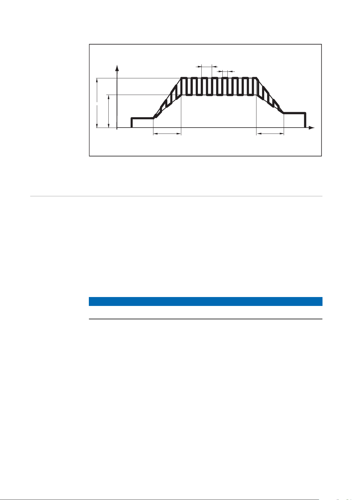
The way that the hosepack is arranged has a significant effect on the properties
of the plasma arc. Depending on the length and arrangement of the hosepack, a
high plasma system inductance can be produced, especially during pulsing. The
increase in current is limited.
Plasma stability can be optimized by
modifying the hosepack arrangement.
The hosepack must always be arranged
as shown in the diagram.
Correct hosepack arrangement
Displaying
Plasma System
Inductance L
Measure plasma system resistance r
1
Use the left or right parameter selection button to select setup parameter "L"
2
The right digital display shows the plasma system inductance (e.g. 5 microhenry).
62

The Gas Menu
I
minImax
I
t
G-H
G-L
(1)
(2)
General The gas menu gives easy access to the gas settings.
EN-US
Accessing the
Gas Menu
Adjusting Parameters
Parameters in
the Gas Menu
1
Press and hold the store button
2
Press the gas-test button
The power source in now located in the gas menu; the last selected parameter is displayed.
Use the left or right parameter selection button to select the parameter to
1
adjust
Use the selection dial to change the parameter value
2
GPr Gas pre-flow time
0.0 - 9.9 s
Factory setting: 0.4 s
G-L Gas post-flow time increase at minimum process current
0 - 25 s
Factory setting: 5 s
G-H Gas post-flow time increase at maximum process current
0 - 40 s / Aut
Factory setting: Aut
The setting for G-H only applies if the maximum process current is actually set. The actual value results from the process current at that moment. With a medium process current, the actual value is half the setting
for G-H, for example.
IMPORTANT! The settings for setup parameters G-L and G-H are added
together. For example, if both parameters are at their maximum (25 s / 40
s), the gas post-flow time lasts for
25 s at minimum process current
65 s at maximum process current
45 s if the process current is exactly halfway between the minimum and
maximum current values.
In the Aut setting, the gas post-flow time G-H is calculated automatically.
Gas post-flow time subject to the process current:
(1) = present gas post-flow time, (2) = present process current,
G-H = post-flow at I
, G-L = post-flow at I
max
min
63

GAS Set value for the flow of process gas
("Digital Gas Control" option)
OFF / 5.0 - max l/min (OFF / 10.71 - max. cfh)
Factory setting: 15 l/min (32.14 cfh)
IMPORTANT! More detailed explanations of the "GAS" parameter can be
found in the "Digital Gas Control" Operating Instructions.
GPU Gas pre-purging
OFF / 0.1 - 10.0 min
Factory setting: OFF
Gas pre-purging starts as soon as a value is set for GPU.
For safety reasons, it is necessary to re-enter a value for GPU in order to
re-start gas pre-purging.
IMPORTANT! Gas pre-purging is mainly required if condensate has built
up after longer periods of downtime in the cold. Long hosepacks in particular may be affected by this.
Exiting the
Setup Menu
1
Press the store button
64

The Job Correction Menu
General Setup parameters can be adapted to meet the specific requirements of individual
jobs in the job correction menu.
EN-US
Accessing the
Job Correction
Menu
Adjusting Parameters
Correctable
Parameters in
the Job Correction Menu
1
Press the operating mode button to select "Job Mode"
2
Press and hold the store button
3
Press the operating mode button
The power source is now located in the job correction menu. The first "Job"
parameter is displayed. The "Job" parameter is used to select the job for
which the parameters are to be adapted.
Use the selection dial to select the job with parameters to be adjusted
1
Use the left or right parameter selection button to select the parameter to be
2
corrected
Use the selection dial to change the parameter value
3
IMPORTANT! The adjusted parameters are immediately saved and applied to
the plasma process.
NOTE!
Some parameters are specific to the job correction menu and relate, for example, to changing settings that were affected the first time the job was saved
on the control panel.
The list below contains the corresponding explanation and details of the adjustment ranges for these parameters.
The following parameters can be adjusted for each saved job:
Eld Electrode diameter
OFF - max. mm (OFF - max. in.)
Factory setting: 4.8 mm (0.189 in.)
I-S Starting current I
0 - 200% (of main current I
start
main
)
Factory setting: 35%
UPS UpSlope t
Transition time from starting current I
up
to main current I
start
OFF / 0.01 - 9.9 s
Factory setting: 0.5 s
I-1 Main current I
main
35 - 200 A
Factory setting: -
main
65

dSL DownSlope t
Transition time from main current I
OFF / 0.01 - 9.9 s
Factory setting: 1.0 s
down
to final current I
main
end
I-E Final current I
0 - 100% (of main current I
end
main
)
Factory setting: 30%
GAS Set value for the flow of process gas
("Digital Gas Control" option)
OFF / 5.0 - max l/min (OFF / 10.71 - max. cfh)
Factory setting: 15 l/min (32.14 cfh)
Cor Gas correction
For entering a gas correction factor for the process gas
(only in conjunction with the "digital gas control" or "external gas regulator" options)
Aut / 1.0 - 10.0
Factory setting: Aut
JSL Job slope
Time for a smooth transition of the process current from the job in question to the job next in line
OFF / 0.1 - 9.9 s
Factory setting: OFF
IMPORTANT! "JSL" job slope can be adjusted separately for each saved
job.
It is only possible to progress from one job to the next without interrupting the plasma process with a robot interface or a fieldbus.
GPr Gas pre-flow time
0.0 - 9.9 s
Factory setting: 0.4 s
G-L Gas post-flow time increase at minimum process current
0 - 25 s
Factory setting: 5 s
G-H Gas post-flow time increase at maximum process current
0 - 40 s / Aut
Factory setting: Aut
More information about the G-H parameter can be found on page 63.
F-P Pulse frequency
OFF / 0, 20 Hz - 2.00 kHz
Factory setting: OFF
66
More information about the F-P parameter can be found on page 45.

dCY Duty cycle
Relationship between pulse duration and base current duration at the set
pulse frequency
10 - 90%
Factory setting: 50%
I-G Base current
0 - 100% (of main current I
Factory setting: 50%
tri Operating mode selection
2t / 4t
2t = operating mode is 2-step mode
4t = operating mode is 4-step mode
t-S Starting current time
OFF / 0.01 - 9.9 s
Factory setting: OFF
More information about the t-S parameter can be found on page 56.
t-E Final current time
OFF / 0.01 - 9.9 s
Factory setting: OFF
main
EN-US
)
Exiting the Job
Correction Menu
More information on the t-E parameter can be found on page 56.
I-c I
correction range for job retrieval
main
OFF / 1 - 100%
Factory setting: OFF
All the settings in the jobs are fixed and saved. Parameter I-c, however, allows the main current I
Example
Setup parameter I-c was set to 30%.
Main current I
IMPORTANT! Each subsequent correction to the main current I
set when the plasma power source is switched off.
1
Press the store button
to be subsequently corrected.
main
can be reduced or increased by up to 30%.
main
main
is re-
67

68

Troubleshooting and Maintenance
69

70

Troubleshooting
General Digital power sources are equipped with an intelligent safety system, which com-
pletely negates the need for fuses (except for the coolant pump fuse). After correcting a possible error, the power source can be properly operated again without
having to change any fuses.
EN-US
Safety
WARNING!
Danger from incorrect operation and work that is not carried out properly.
This can result in serious personal injury and damage to property.
All the work and functions described in this document must only be carried
▶
out by technically trained and qualified personnel.
Read and understand this document in full.
▶
Read and understand all safety rules and user documentation for this equip-
▶
ment and all system components.
WARNING!
Danger from electrical current.
This can result in serious personal injury and damage to property.
Before starting work, switch off all devices and components involved, and
▶
disconnect them from the grid.
Secure all devices and components involved so they cannot be switched back
▶
on.
After opening the device, use a suitable measuring instrument to check that
▶
electrically charged components (such as capacitors) have been discharged.
WARNING!
Displayed Service Codes
Danger due to insufficient ground conductor connection.
This can result in serious personal injury and damage to property.
The housing screws provide a suitable ground conductor connection for
▶
grounding the housing.
The housing screws must not under any circumstances be replaced by other
▶
screws without a reliable ground conductor connection.
If an error message that is not listed here appears on the displays, the error can
only be corrected by service personnel. Please note the displayed error message,
as well as the serial number and configuration of the power source, and contact
the After-Sales Service team with a detailed description of the error.
no | Prg
Cause:
Remedy:
No preconfigured program has been selected
Select a configured program
71

tP1 | xxx
Note: xxx stands for a temperature value
Cause:
Remedy:
tP2 | xxx
Note: xxx stands for a temperature value
Cause:
Remedy:
tP3 | xxx
Note: xxx stands for a temperature value
Cause:
Remedy:
tP4 | xxx
Note: xxx stands for a temperature value
Cause:
Remedy:
tP5 | xxx
Note: xxx stands for a temperature value
Overtemperature in the primary circuit of the power source
Leave power source to cool
Overtemperature in the primary circuit of the power source
Leave power source to cool
Overtemperature in the primary circuit of the power source
Leave power source to cool
Overtemperature in the primary circuit of the power source
Leave power source to cool
Cause:
Remedy:
tP6 | xxx
Note: xxx stands for a temperature value
Cause:
Remedy:
tS1 | xxx
Note: xxx stands for a temperature value
Cause:
Remedy:
tS2 | xxx
Note: xxx stands for a temperature value
Cause:
Remedy:
tS3 | xxx
Note: xxx stands for a temperature value
Overtemperature in the primary circuit of the power source
Leave power source to cool
Overtemperature in the primary circuit of the power source
Leave power source to cool
Overtemperature in the secondary circuit of the power source
Leave power source to cool
Overtemperature in the secondary circuit of the power source
Leave power source to cool
72
Cause:
Remedy:
Overtemperature in the secondary circuit of the power source
Leave power source to cool

tSt | xxx
Note: xxx stands for a temperature value
Cause:
Remedy:
Err | 049
Cause:
Remedy:
Err | 050
Cause:
Remedy:
Err | 051
Cause:
Remedy:
Err | 052
Cause:
Remedy:
no | IGn
Cause:
Remedy:
Overtemperature in the control circuit of the power source
EN-US
Leave power source to cool
Phase error in the power supply
Check the mains fuse, the grid lead and the mains plug
Indirect symmetry error
Contact After-Sales Service
Mains undervoltage: Mains voltage has fallen below the tolerance
range (see "Technical Data" section)
Check the mains voltage
Mains overvoltage: Mains voltage has exceeded the tolerance range
(see "Technical Data" section)
Check the mains voltage
The ignition time-out function is active; current did not start flowing
within the time specified in the Setup menu. The power source safety
cut-out has tripped
Check the plasma torch wearing parts; if necessary, increase the
period of time in the "2nd Level Setup Menu" to the safety cut-out
Err | PE
Cause:
Remedy:
Err | IP
Cause:
Remedy:
Err | bPS
Cause:
Remedy:
dSP | Axx
Cause:
Remedy:
dSP | Cxx
Cause:
Remedy:
The earth current watchdog has triggered the safety cut-out of the
power source.
Switch off the power source, wait for 10 seconds and then switch it
back on again; if the error occurs again despite numerous attempts to
eliminate it - contact After-Sales Service
Primary overcurrent
Contact After-Sales Service
Power module error
Contact After-Sales Service
Error in the central control and regulation unit
Contact After-Sales Service
Error in the central control and regulation unit
Contact After-Sales Service
dSP | Exx
Cause:
Remedy:
Error in the central control and regulation unit
Contact After-Sales Service
73

dSP | Sy
Cause:
Remedy:
dSP | nSy
Cause:
Remedy:
r | E30
Cause:
Remedy:
r | E31
Cause:
Remedy:
r | E33
Cause:
Remedy:
Error in the central control and regulation unit
Contact After-Sales Service
Error in the central control and regulation unit
Contact After-Sales Service
r adjustment: There is no contact between the electrode and the
plasma nozzle
Establish a proper connection between the electrode and the plasma
nozzle
r adjustment: Process was interrupted by repeatedly pressing the
gas-test button
Establish a proper connection between the electrode and the plasma
nozzle
Press the gas-test button once
r adjustment: Poor contact between the electrode and the plasma
nozzle
Check the plasma torch wearing parts
r | E34
Cause:
Remedy:
no | Arc
Cause:
Remedy:
no | H2O
Cause:
Remedy:
hot | H2O
Cause:
Remedy:
-St | oP-
When operating the power source with a robot interface or field coupler
r adjustment: Poor contact between the electrode and the plasma
nozzle
Check the plasma torch wearing parts
Plasma arc break
Check plasma torch wearing parts, check process parameters and
gas flow rate
Cooling unit flow sensor trips
Check the cooling unit; if necessary, top-up with coolant or vent the
coolant supply, as per the "Starting up the Cooling Unit" section
Cooling unit thermostat trips
Wait until the end of the cooling phase, when "Hot | H2O" is no longer
displayed.
ROB 5000 or fieldbus coupler for robot control: Before resuming the
plasma process, set the "Source error reset" signal.
74
Cause:
Remedy:
Robot not ready
Set the "Robot ready" signal, set the "Source error reset" signal
("Source error reset" only for ROB 5000 and fieldbus coupler for robot control)

Power Source
Troubleshooting
Power source not working
Power source switched on; displays and indicators do not illuminate
EN-US
Cause:
Remedy:
Cause:
Remedy:
Cause:
Remedy:
No plasma arc
Power switch ON, overtemperature indicator illuminates
Cause:
Remedy:
Cause:
Remedy:
Cause:
Remedy:
Grid lead damaged or broken, mains plug not inserted
Check grid lead, insert mains plug if necessary
Grid socket or mains plug faulty
Replace faulty parts
Mains fuse protection
Replace mains fuse
Overloading
Take duty cycle into account
Automatic thermal circuit breaker has tripped
Wait until the power source automatically comes back on after the
end of the cooling phase
Fan in the power source is faulty
Contact After-Sales Service
No gas
All other functions are OK
Cause:
Remedy:
Cause:
Remedy:
Cause:
Remedy:
Cause:
Remedy:
Cause:
Remedy:
Poor plasma qualities
Cause:
Remedy:
Gas cylinder empty
Replace gas cylinder
Faulty gas pressure regulator
Replace the gas pressure regulator
Gas hose is not fitted or is damaged
Fit or replace gas hose
Faulty plasma torch
Replace the plasma torch
Faulty gas solenoid valve
Contact After-Sales Service
Incorrect process parameters
Check settings
75

Plasma torch gets very hot
Cause:
Remedy:
Plasma torch is under-dimensioned
Observe duty cycle and load limits
Cause:
Remedy:
Cause:
Remedy:
Coolant flow too low
Check coolant level, coolant flow rate, water contamination, etc. If
coolant pump blocked: use a screwdriver to turn on the shaft of the
coolant pump at the gland
Parameter C-C is set to "OFF".
In the Setup menu, set parameter C-C to "Aut" or "ON".
76

Service, maintenance and disposal
General The plasma power source only requires minimal care and maintenance under nor-
mal operating conditions. However, several points must be observed in order for
the plasma power source to remain operational for years to come.
EN-US
Safety
WARNING!
Danger from incorrect operation and work that is not carried out properly.
This can result in serious personal injury and damage to property.
All the work and functions described in this document must only be carried
▶
out by technically trained and qualified personnel.
Read and understand this document in full.
▶
Read and understand all safety rules and user documentation for this equip-
▶
ment and all system components.
WARNING!
Danger from electrical current.
This can result in serious personal injury and damage to property.
Before starting work, switch off all devices and components involved, and
▶
disconnect them from the grid.
Secure all devices and components involved so they cannot be switched back
▶
on.
After opening the device, use a suitable measuring instrument to check that
▶
electrically charged components (such as capacitors) have been discharged.
WARNING!
At every startup
Every 2 Months
Danger due to insufficient ground conductor connection.
This can result in serious personal injury and damage to property.
The housing screws provide a suitable ground conductor connection for
▶
grounding the housing.
The housing screws must not under any circumstances be replaced by other
▶
screws without a reliable ground conductor connection.
Check for damage to the mains plug and mains cable, as well as the plasma
-
torch and hosepack
Check if the all-round clearance of the device is 0.5 m (1 ft. 8 in.) so that
-
cooling air can circulate unimpeded
NOTE!
Air intake and exhaust openings must also not be blocked or even partially
covered.
If present: clean air filter
-
77

Every 6 Months
Danger due to the effect of compressed air.
This can result in damage to property.
▶
Danger of electric shock due to grounding cable and device grounding points
not being connected properly.
An electric shock can be fatal.
▶
Disposal Materials should be disposed of according to valid local and national regulations.
CAUTION!
Do not bring the air nozzle too close to electronic parts.
Dismantle device side panels and blow the inside of the device clean with dry,
1
reduced compressed air
Also clean the cooling air ducts if there is a large accumulation of dust
2
WARNING!
When refitting the side panels, ensure that the grounding cable and device
grounding points are properly connected.
78

Appendix
79

80

Technical data
EN-US
Special Voltage
Acerios
CAUTION!
An inadequately dimensioned electrical installation can lead to serious damage.
The grid lead and its fuse protection should be designed accordingly.
▶
The technical data on the rating plate should be followed.
▶
Mains voltage 3 x 400 V
Mains voltage tolerance ±15%
Grid frequency 50 / 60 Hz
Slow-blow mains fuse protection 35 A
Max. permitted grid impedance Z
Primary continuous power (100% D.C.3))
Cos phi 0.99
Process current range 35 - 200 A
Process current at 10 min/40°C (104°F) 100%
3)
D.C.
max
on PCC
1)
Possible connection
restrictions
10.8 kVA
200 A
2)
Explanation of
Footnotes
Open circuit voltage 97 V
Working voltage 11.4 - 33.0 V
Striking voltage (Up) 9.5 kV
Protection class IP 23
Type of cooling AF
Insulation class F
EMC device class (according to EN/IEC
60974-10)
Dimensions l/w/h (with handle) 625/290/475 mm
24.6/11.4/18.7 in.
Weight 40.3 kg
Marks of conformity S, CE
1)
2)
3)
4)
PCC = interface to a 230/400 V, 50 Hz public grid
Consult the grid operator before connecting the device to the public grid!
D.C. = duty cycle
A device in emissions class A is not intended for use in residential areas in
which the power is supplied via a public low-voltage grid.
The electromagnetic compatibility may be influenced by conducted or radiated radio frequencies.
A
88.85 lb.
4)
81

82

EN-US
83

 Loading...