

Operating
Instructions
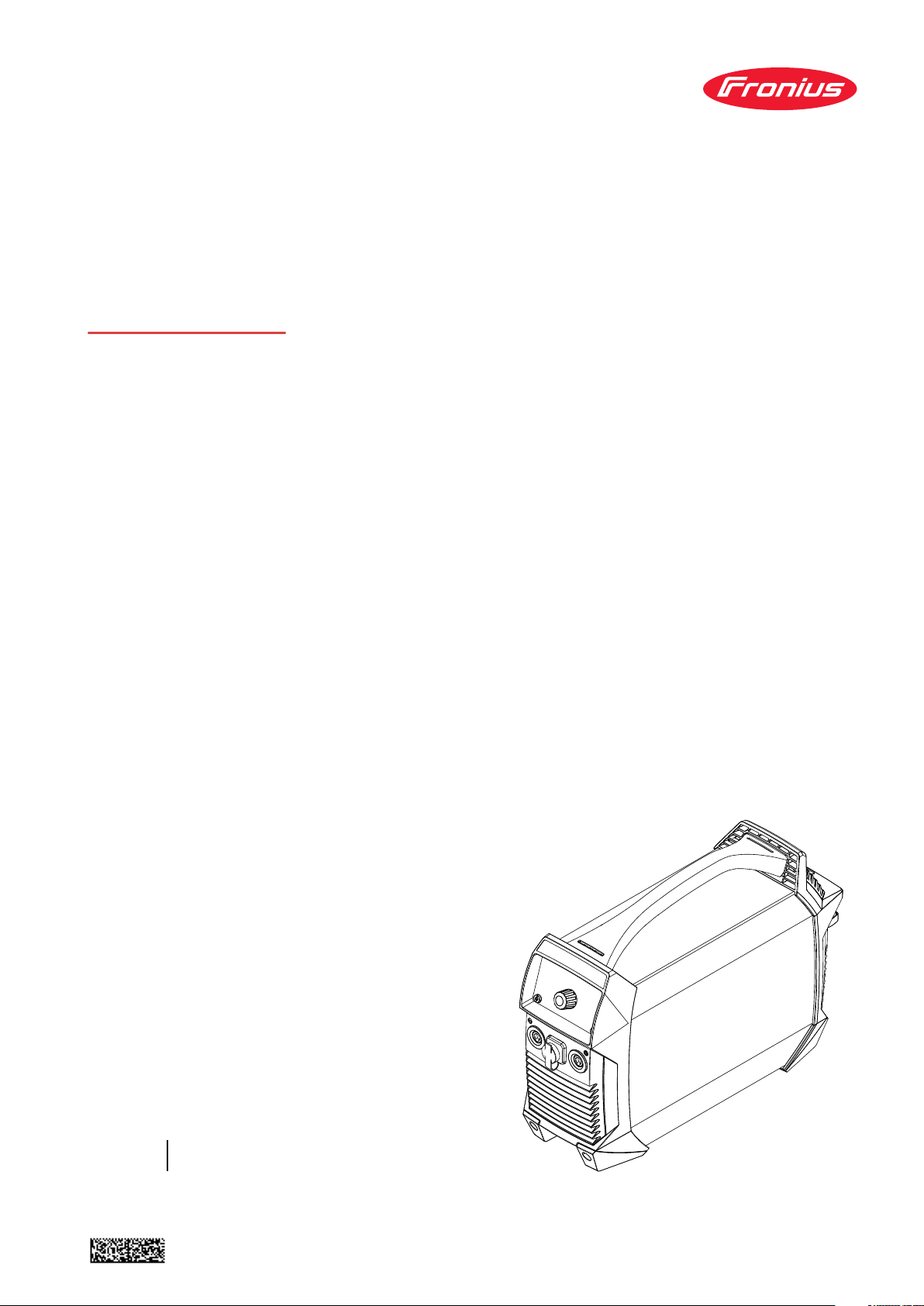
AccuPocket 150/400 TIG
ActiveCharger 1000
Operating instructions
EN
42,0426,0200,EN 034-16082022


Contents
Safety rules 7
General 9
Explanation of safety notices 9
Environmental conditions 9
Obligations of the operator 9
Obligations of personnel 10
EMC Device Classifications 10
Disposal 10
Data protection 10
Copyright 10
Power source 11
General 11
Proper use 11
Protecting yourself and others 12
Noise emission values 12
Danger from toxic gases and vapours 12
Danger from flying sparks 13
Dangers from welding current 13
Dangers from the battery 14
Meandering welding currents 15
EMC measures 15
EMF measures 16
Requirement for the shielding gas 16
Danger from shielding gas cylinders 16
Danger from escaping shielding gas 17
Safety precautions in the place of use and for storage and transport 17
Safety measures in normal operation 18
Safety inspection 18
Commissioning, maintenance and repair 18
Safety symbols 19
Charger 20
General 20
Environmental conditions 20
Intended use 20
Mains connection 20
Dangers from mains current and charging current 21
Protecting yourself and others 21
Safety measures in normal operation 21
EMC measures 22
Maintenance 22
Maintenance and repair 22
Warranty and liability 22
Safety inspection 22
Markings on the device 23
General and electrical risks 23
EN
Power source 25
General 27
Device concept 27
Warning notices on the device 27
Application areas 28
Using rechargeable devices 29
Safety 29
Storage and transport 29
Service life of the battery 29
Battery protection functions 31
3

General 31
Deep discharge protector 31
Automatic switch-off 31
Temperature monitoring 32
Overcharging protection 32
Before commissioning 33
Safety 33
Proper use 33
Setup regulations 33
Power connection 33
Before starting for the first time 34
Control elements and connections 35
Safety 35
Connections and mechanical components 35
Control panel 37
MMA welding 39
Preparatory work 39
MMA welding 39
SoftStart / HotStart function 39
Arc-force dynamic 41
TIG modes 42
Symbols and their explanations 42
2-step mode 42
4-step mode 43
TIG welding 44
General 44
Connecting the gas cylinder 44
Preparation 44
Setting the gas pressure 45
TIG welding 45
TIG Comfort Stop 46
TIG pulsing 48
Tacking function 49
The Setup menu 50
Accessing the Setup menu 50
Changing welding parameters 50
Exiting the Setup menu 50
Parameters for MMA welding 50
Parameters for TIG welding 52
VRD safety device (optional) 54
General 54
Function 54
Care and maintenance 55
Safety 55
General 55
At every start-up 55
Every 2 months 56
Disposal 57
General 57
Safety 57
Removing the rechargeable battery pack 58
Troubleshooting 61
Safety 61
Indicated errors 61
Service messages 62
No function 63
Faulty operation 64
Technical data 66
Environmental conditions 66
Explanation of the term "duty cycle" 66
Technical data 67
4

Charger 69
General 71
Warning notices on the device 71
Warning notices inside the device 72
Intended use 72
Before commissioning 73
Mains connection 73
Generator-powered operation 73
Setup regulations 73
Space requirements 74
Control elements and connections 75
Safety 75
Connections and components 75
Control panel 75
Start-up 76
Safety 76
Commissioning 76
Operating modes 77
Options 78
Fitting the wall bracket 78
Troubleshooting 79
Safety 79
Indicated errors 79
No function 79
Technical data 80
Environmental conditions 80
Technical data 230V 81
Standards 230V 81
Technical data 120V 82
Standards 120V 82
Technical data 100V 83
Standards 100V 83
EN
5

6

Safety rules
7

8
General
EN
Explanation of
safety notices
DANGER!
Indicates immediate danger.
If not avoided, death or serious injury will result.
▶
WARNING!
Indicates a potentially hazardous situation.
If not avoided, death or serious injury may result.
▶
CAUTION!
Indicates a situation where damage or injury could occur.
If not avoided, minor injury and/or damage to property may result.
▶
NOTE!
Indicates a risk of flawed results and possible damage to the equipment.
Environmental
conditions
Transport, storage or operation of the device outside the stipulated range will be
deemed improper. The manufacturer shall not be held liable for any damage
arising from such usage.
Ambient air temperature range:
During operation: -10 °C to + 40 °C (14 °F to 104 °F)
-
During transport: -20 °C to +55 °C (-4 °F to 131 °F)
-
Recommended temperature range during charging:
-
+ 4 °C to + 40 °C (+ 39.2 °F to + 104 °F)
Recommended temperature range during storage:
-
0 °C to + 20 °C (+ 32 °F to + 68 °F)
When placing in storage, the state of charge should ideally be at 50 - 80%
(corresponds to approx. 2 to 3 bars on the charging status indication).
Relative humidity:
Up to 50% at 40 °C (104 °F)
-
Up to 90 % at 20 °C (68 °F)
-
The surrounding air must be free from dust, acids, corrosive gases or substances,
etc.
Can be used at altitudes up to 2000 m (6561 ft.)
Obligations of
the operator
The operator must only allow persons to work with the device who:
are familiar with the fundamental instructions regarding safety at work and
-
accident prevention and have been instructed in how to use the device
have read and understood these operating instructions, especially the sec-
-
tion "safety rules", and have confirmed as much with their signatures
are trained to produce the required results.
-
9

Checks must be carried out at regular intervals to ensure that operators are
working in a safety-conscious manner.
Obligations of
personnel
EMC Device
Classifications
Disposal Waste electrical and electronic equipment must be collected separately and re-
Before using the device, all persons instructed to do so undertake:
to observe the basic instructions regarding safety at work and accident pre-
-
vention
to read these operating instructions, especially the "Safety rules" section and
-
sign to confirm that they have understood them and will follow them.
Before leaving the workplace, ensure that people or property cannot come to any
harm in your absence.
Devices in emission class A:
Are only designed for use in industrial settings
-
Can cause line-bound and radiated interference in other areas
-
Devices in emission class B:
Satisfy the emissions criteria for residential and industrial areas. This is also
-
true for residential areas in which the energy is supplied from the public lowvoltage mains.
EMC device classification as per the rating plate or technical data.
cycled in an environmentally-friendly way, in accordance with the European Directive and national legislation. Used equipment must be returned to the distributor or disposed of via an approved local collection and disposal facility. Correct
disposal of used equipment promotes the sustainable recycling of material resources. Failing to dispose of used equipment correctly can lead to adverse
health and/or environmental impacts.
Packaging materials
Separate collection according to material. Check your local authority regulations.
Crush containers to reduce size.
Data protection The user is responsible for the safekeeping of any changes made to the factory
settings. The manufacturer accepts no liability for any deleted personal settings.
Copyright Copyright of these operating instructions remains with the manufacturer.
The text and illustrations are all technically correct at the time of printing. We
reserve the right to make changes. The contents of the operating instructions
shall not provide the basis for any claims whatsoever on the part of the purchaser. If you have any suggestions for improvement, or can point out any mistakes that you have found in the instructions, we will be most grateful for your
comments.
10

Power source
General The device is manufactured using state-of-the-art technology and according to
recognised safety standards. If used incorrectly or misused, however, it can
cause:
injury or death to the operator or a third party,
-
damage to the device and other material assets belonging to the operating
-
company,
inefficient operation of the device.
-
All persons involved in commissioning, operating, maintaining and servicing the
device must:
be suitably qualified,
-
have sufficient knowledge of welding and
-
read and follow these operating instructions carefully.
-
The operating instructions must always be at hand wherever the device is being
used. In addition to the operating instructions, attention must also be paid to any
generally applicable and local regulations regarding accident prevention and environmental protection.
All safety and danger notices on the device
must be in a legible state,
-
must not be damaged,
-
must not be removed,
-
must not be covered, pasted or painted over.
-
EN
For the location of the safety and danger notices on the device, refer to the section headed "General" in the operating instructions for the device.
Before switching on the device, rectify any faults that could compromise safety.
This is for your personal safety!
Proper use The device is to be used exclusively for its intended purpose.
The device is intended solely for the welding processes specified on the rating
plate.
Any use above and beyond this purpose is deemed improper. The manufacturer
shall not be held liable for any damage arising from such usage.
Proper use includes:
carefully reading and following all the instructions given in the operating in-
-
structions
studying and obeying all safety and danger notices carefully
-
performing all stipulated inspection and maintenance work.
-
Never use the device for the following purposes:
Thawing out pipes
-
Charging batteries
-
Starting engines
-
The device is designed for use in industry and the workshop. The manufacturer
accepts no responsibility for any damage caused through use in a domestic setting.
The manufacturer likewise accepts no liability for inadequate or incorrect results.
11

Protecting yourself and others
Anyone working with the device exposes themselves to numerous risks, e.g.
flying sparks and hot pieces of metal
-
Arc radiation, which can damage eyes and skin
-
Hazardous electromagnetic fields, which can endanger the lives of those us-
-
ing cardiac pacemakers
Risk of electrocution from mains current and welding current
-
Greater noise pollution
-
Harmful welding fumes and gases
-
Suitable protective clothing must be worn when working with the device. The
protective clothing must have the following properties:
Flame-resistant
-
Insulating and dry
-
Covers the whole body, is undamaged and in good condition
-
Safety helmet
-
Trousers with no turn-ups
-
Protective clothing refers to a variety of different items. Operators should:
Protect eyes and face from UV rays, heat and sparks using a protective visor
-
and regulation filter
Wear regulation protective goggles with side protection behind the protect-
-
ive visor
Wear stout footwear that provides insulation even in wet conditions
-
Protect the hands with suitable gloves (electrically insulated and providing
-
protection against heat)
Wear ear protection to reduce the harmful effects of noise and to prevent in-
-
jury
Noise emission
values
Keep all persons, especially children, out of the working area while any devices
are in operation or welding is in progress. If, however, there are people in the vicinity:
Make them aware of all the dangers (risk of dazzling by the arc, injury from
-
flying sparks, harmful welding fumes, noise, possible risks from mains current and welding current, etc.)
Provide suitable protective equipment
-
Alternatively, erect suitable safety screens/curtains.
-
The device generates a maximum sound power level of <80 dB(A) (ref. 1pW)
when idling and in the cooling phase following operation at the maximum permissible operating point under maximum rated load conditions according to EN
60974-1.
It is not possible to provide a workplace-related emission value during welding
(or cutting) as this is influenced by both the process and the environment. All
manner of different welding parameters come into play, including the welding
process (MIG/MAG, TIG welding), the type of power selected (DC or AC), the
power range, the type of weld metal, the resonance characteristics of the workpiece, the workplace environment, etc.
Danger from toxic gases and vapours
12
The fumes produced during welding contain harmful gases and vapours.
Welding fumes contain substances that cause cancer, as stated in Monograph
118 of the International Agency for Research on Cancer.
Use at-source extraction and a room extraction system.
If necessary, use a welding torch with an integrated extraction device.

Keep your face away from welding fumes and gases.
Fumes and hazardous gases
must not be breathed in
-
must be extracted from the working area using appropriate methods.
-
Ensure an adequate supply of fresh air. Ensure that there is a ventilation rate of
at least 20 m³ per hour at all times.
Otherwise, a welding helmet with an air supply must be worn.
If there is any doubt about whether the extraction capacity is sufficient, the
measured toxic emission values should be compared with the permissible limit
values.
The following components are responsible, amongst other things, for the degree
of toxicity of welding fumes:
Metals used for the workpiece
-
Electrodes
-
Coatings
-
Cleaners, degreasers, etc.
-
Welding process used
-
The relevant material safety data sheets and manufacturer's specifications for
the listed components should therefore be studied carefully.
Recommendations for trade fair scenarios, risk management measures and for
identifying working conditions can be found on the European Welding Association website under Health & Safety (https://european-welding.org).
EN
Danger from fly-
ing sparks
Flammable vapours (e.g. solvent fumes) should be kept away from the arc's radiation area.
Close the shielding gas cylinder valve or main gas supply if no welding is taking
place.
Flying sparks may cause fires or explosions.
Never weld close to flammable materials.
Flammable materials must be at least 11 metres (36 ft. 1.07 in.) away from the
arc, or alternatively covered with an approved cover.
A suitable, tested fire extinguisher must be available and ready for use.
Sparks and pieces of hot metal may also get into adjacent areas through small
gaps or openings. Take appropriate precautions to prevent any danger of injury or
fire.
Welding must not be performed in areas that are subject to fire or explosion or
near sealed tanks, vessels or pipes unless these have been prepared in accordance with the relevant national and international standards.
Do not carry out welding on containers that are being or have been used to store
gases, propellants, mineral oils or similar products. Residues pose an explosive
hazard.
Dangers from
welding current
An electric shock is potentially life threatening and can be fatal.
Do not touch live parts either inside or outside the device.
13

Make sure that you and others are protected with an adequately insulated, dry
temporary backing or cover for the earth or ground potential. This temporary
backing or cover must extend over the entire area between the body and the
earth or ground potential.
All cables and leads must be secured, undamaged, insulated and adequately dimensioned. Loose connections, scorched, damaged or inadequately dimensioned
cables and leads must be replaced immediately.
Do not sling cables or leads around the body or parts of the body.
The electrode (rod electrode, tungsten electrode, welding wire, etc.) must
never be immersed in liquid for cooling
-
never be touched when the power source is switched on.
-
Double the open circuit voltage of a power source can occur between the welding
electrodes of two power sources. Touching the potentials of both electrodes at
the same time may be fatal under certain circumstances.
If necessary, provide an adequate earthing connection for the workpiece.
Switch off unused devices.
Dangers from
the battery
The substances contained in the battery used in this device can be harmful to
the environment and to human and animal health.
If the device becomes damaged, please observe the following points:
Make sure that leaking fluids cannot get into the soil or groundwater
-
If pollution has already occurred, it must be removed in accordance with rel-
-
evant national regulations
Liquid may leak from the battery if used or stored under improper conditions.
The liquid may cause irritation or burns.
-
Avoid contact with this liquid.
-
In case of accidental contact, clean the affected area immediately with wa-
-
ter.
In case of eye contact, also consult a doctor.
-
The battery can catch fire if overheated. Do not expose the device to heat
(e.g. a permanent heat source or fire)
If the battery is damaged or subjected to improper use, dangerous vapours may
be given off which can irritate the airways.
If this happens:
Ensure an adequate supply of fresh air
-
Seek medical attention in case of discomfort
-
With a faulty battery, liquid may leak out of the device.
Avoid contact with the liquid
-
Hand the device over to a Fronius Service Partner for repair
-
Clean and check any parts that have come into contact with the liquid
-
14
Do not operate or store the device in a potentially explosive atmosphere.
Special regulations apply in rooms at risk of fire or explosion.
Observe relevant national and international regulations.
To comply with European Directive 2006/66/EC on batteries and accumulators
and its implementation in national law, batteries and rechargeable batteries that
have reached the end of their life must be collected separately and returned to
an approved recycling facility. Be sure to return any device that you no longer require to your distributor, or find out about the approved collection and recycling

facilities in your area. Ignoring this European Directive may have potentially adverse effects on the environment and your health!
Devices with mechanically undamaged rechargeable batteries may be returned to
the relevant Fronius Service Partner for repair or battery replacement.
As soon as it becomes evident that the rechargeable battery has been mechanically damaged (e.g. electrolyte is escaping), dispose of the device at your nearest
recycling centre in accordance with national laws and guidelines.
If anything is unclear or you have any questions about disposal, contact your
Fronius Service Partner.
Use only the "ActiveCharger 1000" battery charger to charge the power source.
Use of a different charger poses a fire risk.
Only operate the power source using the battery provided. Use of a different battery could result in the risk of injury and/or fire.
If the battery is disconnected, keep it away from metal objects such as paperclips, coins, keys, nails, screws or other small metal objects that could establish a
connection between the battery terminals. Short circuiting of the battery poles
could result in a burn injury or a fire.
Do not use damaged or modified batteries and power sources. Damaged or modified components and devices may exhibit unpredictable behaviour that could result in an explosion or injury.
EN
Meandering
welding currents
Do not expose the power source and the battery to fire or temperatures exceeding 130 °C (266 °F). This could result in an explosion.
Follow the charging instructions contained in these Operating Instructions. Do
not charge the battery outside of the permitted temperature range - see sectionEnvironmental conditions on page 20. Improper charging or exposure to
unauthorised temperatures could damage the battery and increase the risk of
fire.
If the following instructions are ignored, meandering welding currents can develop with the following consequences:
Fire hazard
-
Overheating of parts connected to the workpiece
-
Irreparable damage to ground conductors
-
Damage to device and other electrical equipment
-
Ensure that the workpiece is held securely by the workpiece clamp.
Attach the workpiece clamp as close as possible to the area that is to be welded.
If the floor is electrically conductive, the device must be set up with sufficient
insulating material to insulate it from the floor.
If distribution boards, twin-head mounts, etc., are being used, note the following:
The electrode of the welding torch / electrode holder that is not used is also live.
Make sure that the welding torch / electrode holder that is not used is kept sufficiently insulated.
EMC measures In certain cases, even though a device complies with the standard limit values for
emissions, it may affect the application area for which it was designed (e.g. when
15

there is sensitive equipment at the same location, or if the site where the device
is installed is close to either radio or television receivers).
If this is the case, then the operator is obliged to take appropriate action to rectify the situation.
Check and evaluate the immunity to interference of nearby devices according to
national and international regulations. Examples of equipment that may be susceptible to interference from the device include:
Safety devices
-
Network, signal and data transfer lines
-
IT and telecommunications devices
-
Measuring and calibrating devices
-
Supporting measures for avoidance of EMC problems:
Mains supply
1.
If electromagnetic interference arises despite the correct mains connec-
-
tion, additional measures are necessary (e.g. use of a suitable line filter)
Welding power-leads
2.
must be kept as short as possible
-
must be laid close together (to avoid EMF problems)
-
must be kept well apart from other leads
-
Equipotential bonding
3.
Earthing of the workpiece
4.
If necessary, establish an earth connection using suitable capacitors.
-
Shield, if necessary
5.
Shield other devices nearby
-
Shield the entire welding installation
-
EMF measures Electromagnetic fields may pose as yet unknown risks to health:
Effects on the health of persons in the vicinity, e.g. those with pacemakers
-
and hearing aids
Individuals with pacemakers must seek advice from their doctor before ap-
-
proaching the device or any welding that is in progress
For safety reasons, maintain as large a distance as possible between the
-
welding power-leads and the head/torso of the welder
Do not carry welding power-leads and hosepacks over the shoulders or wind
-
them around any part of the body
Requirement for
the shielding gas
Danger from
shielding gas cylinders
Especially with ring lines, contaminated shielding gas can cause damage to
equipment and reduce welding quality.
Meet the following requirements regarding shielding gas quality:
Solid particle size < 40 µm
-
Pressure condensation point < -20 °C
-
Max. oil content < 25 mg/m³
-
Use filters if necessary.
Shielding gas cylinders contain gas under pressure and can explode if damaged.
As the shielding gas cylinders are part of the welding equipment, they must be
handled with the greatest of care.
16
Protect shielding gas cylinders containing compressed gas from excessive heat,
mechanical impact, slag, naked flames, sparks and arcs.
Mount the shielding gas cylinders vertically and secure according to instructions
to prevent them falling over.

Keep the shielding gas cylinders well away from any welding or other electrical
circuits.
Never hang a welding torch on a shielding gas cylinder.
Never touch a shielding gas cylinder with an electrode.
Risk of explosion - never attempt to weld a pressurised shielding gas cylinder.
Only use shielding gas cylinders suitable for the application in hand, along with
the correct and appropriate accessories (regulator, hoses and fittings). Only use
shielding gas cylinders and accessories that are in good condition.
Turn your face to one side when opening the valve of a shielding gas cylinder.
Close the shielding gas cylinder valve if no welding is taking place.
If the shielding gas cylinder is not connected, leave the valve cap in place on the
cylinder.
The manufacturer's instructions must be observed as well as applicable national
and international regulations for shielding gas cylinders and accessories.
EN
Danger from escaping shielding
gas
Safety precautions in the place
of use and for
storage and
transport
Risk of suffocation from the uncontrolled escape of shielding gas
Shielding gas is colourless and odourless and, in the event of a leak, can displace
the oxygen in the ambient air.
Ensure an adequate supply of fresh air with a ventilation rate of at least
-
20 m³/hour.
Observe safety and maintenance instructions on the shielding gas cylinder or
-
the main gas supply.
Close the shielding gas cylinder valve or main gas supply if no welding is tak-
-
ing place.
Check the shielding gas cylinder or main gas supply for uncontrolled gas
-
leakage before every start-up.
A toppling device can cause life-threatening injuries. Place the device on a solid,
level surface so that it remains stable
The maximum permissible tilt angle is 10°.
-
Do not operate or store the device in a potentially explosive atmosphere.
Special regulations apply in rooms at risk of fire or explosion.
Observe relevant national and international regulations.
Use internal directives and checks to ensure that the workplace environment is
always clean and clearly laid out.
Only set up and operate the device in accordance with the degree of protection
shown on the rating plate.
When setting up the device, ensure there is an all-round clearance of 0.5 m (1 ft.
7.69 in.) to ensure that cooling air can flow in and out freely.
When transporting the device, observe the relevant national and local guidelines
and accident prevention regulations. This applies especially to guidelines regarding the risks arising during transport.
After transporting the device, it must be visually inspected for damage before
commissioning. Any damage must be repaired by trained service technicians before commissioning the device.
17

Odourless and colourless shielding gas may escape unnoticed if an adapter is
used for the shielding gas connection. Prior to assembly, seal the device-side
thread of the adapter for the shielding gas connection using suitable Teflon tape.
Safety measures
in normal operation
Safety inspection
Only operate the device if all safety devices are fully functional. If the safety
devices are not fully functional, there is a risk of
injury or death to the operator or a third party,
-
damage to the device and other material assets belonging to the operator,
-
inefficient operation of the device.
-
Any safety devices that are not functioning properly must be repaired before
switching on the device.
Never bypass or disable safety devices.
Before switching on the device, ensure that no one is likely to be endangered.
Check the device at least once a week for obvious damage and proper functioning of safety devices.
The manufacturer recommends that a safety inspection of the device is performed at least once every 12 months.
The manufacturer recommends that the power source be calibrated during the
same 12-month period.
A safety inspection should be carried out by a qualified electrician
after any changes are made
-
after any additional parts are installed, or after any conversions
-
after repair, care and maintenance has been carried out
-
at least every twelve months.
-
Commissioning,
maintenance and
repair
For safety inspections, follow the appropriate national and international standards and directives.
Further details on safety inspection and calibration can be obtained from your
service centre. They will provide you on request with any documents you may require.
It is impossible to guarantee that bought-in parts are designed and manufactured to meet the demands made of them, or that they satisfy safety requirements.
Use only original spare and wearing parts (also applies to standard parts).
-
Do not carry out any modifications, alterations, etc. to the device without the
-
manufacturer's consent.
Components that are not in perfect condition must be replaced immediately.
-
When ordering, please give the exact designation and part number as shown
-
in the spare parts list, as well as the serial number of your device.
The housing screws provide the ground conductor connection for earthing the
housing parts.
Only use original housing screws in the correct number and tightened to the specified torque.
18

Safety symbols Devices with the CE mark satisfy the essential requirements of the low-voltage
and electromagnetic compatibility directives (e.g. relevant product standards of
the EN 60 974 series).
Fronius International GmbH hereby declares that the device is compliant with
Directive 2014/53/EU. The full text on the EU Declaration of Conformity can be
found at the following address: http://www.fronius.com
Devices marked with the CSA test mark satisfy the requirements of the relevant
standards for Canada and the USA.
EN
19

Charger
General The device has been manufactured in line with the state of the art and according
to recognized safety standards. If used incorrectly or misused, however, it can
cause:
Serious or fatal injury to the operator or third parties
-
Damage to the device and other material assets belonging to the operating
-
company
Inefficient operation of the device
-
All persons involved in commissioning, operating, maintaining and servicing the
device must:
Be suitably qualified
-
Read and follow these Operating Instructions carefully
-
The Operating Instructions must always be at hand wherever the device is being
used. In addition to the Operating Instructions, attention must also be paid to
any generally applicable and local regulations regarding accident prevention and
environmental protection.
All safety and danger notices on the device:
Must be kept in a legible state
-
Must not be damaged/marked
-
Must not be removed
-
Must not be covered, pasted, or painted over
-
For the location of the safety and danger notices on the device, refer to the section headed "General information" in the Operating Instructions for your device.
Before switching on the device, rectify any faults that could compromise safety.
This is for your personal safety!
Environmental
conditions
Intended use The device is to be used exclusively for its intended purpose. Any use above and
Operation or storage of the device outside the stipulated area will be deemed as
not in accordance with the intended purpose. The manufacturer shall not be held
liable for any damage arising from such usage.
For exact information on permitted environmental conditions, please refer to the
"Technical data" section.
beyond this purpose is deemed improper. The manufacturer is not liable for any
damage, or unexpected or incorrect results arising out of such misuse.
Proper use also includes:
Carefully reading and following all Operating Instructions, safety and danger
-
notices
Performing all stipulated inspection and servicing work
-
Following all instructions from the battery and vehicle manufacturers
-
Mains connection
20
Proper handling of the device is essential for it to function correctly. Never pull
on the cable when handling the device.
Devices with a higher rating may affect the energy quality of the mains due to
their current consumption.

This may affect a number device types in terms of:
Connection restrictions
-
-
Criteria with regard to the maximum permissible mains impedance
-
Criteria with regard to the minimum short-circuit power requirement
*)
at the interface with the public grid
*)
*)
see "Technical data"
In this case, the plant operator or the person using the device should check
whether the device may be connected, where appropriate by discussing the matter with the power supply company.
IMPORTANT! Ensure that the mains connection is earthed properly
EN
Dangers from
mains current
and charging
current
Protecting yourself and others
Anyone working with chargers exposes themselves to numerous dangers e.g.:
risk of electrocution from mains current and charging current
-
hazardous electromagnetic fields, which can risk the lives of those using car-
-
diac pacemakers
An electric shock can be fatal. Every electric shock is potentially life threatening.
To avoid electric shocks while using the charger:
do not touch any live parts inside or on the outside of the charger.
-
do not short-circuit the charger lead
-
All cables and leads must be secured, undamaged, insulated and adequately dimensioned. Loose connections, scorched, damaged or inadequately dimensioned
cables and leads must be immediately repaired by authorised personnel.
While the charger is in operation, keep all persons, especially children, out of the
working area. If, however, there are people in the vicinity,
warn them of all the dangers,
-
provide suitable protective equipment.
-
Before leaving the work area, ensure that people or property cannot come to any
harm in your absence.
Safety measures
in normal operation
Chargers with a ground conductor must only be operated on a mains supply with
a ground conductor and a socket with a ground conductor contact. If the charger
is operated on a mains supply without a ground conductor or in a socket without
a ground conductor contact, this will be deemed gross negligence. The manufacturer shall not be held liable for any damage arising from such usage.
Only operate the charger in accordance with the degree of protection shown on
the rating plate.
Under no circumstances operate the charger if there is any evidence of damage.
Arrange for the mains cable to be checked regularly by a qualified electrician to
ensure the ground conductor is functioning properly.
Any safety devices and parts that are not functioning properly or are in imperfect
condition must be repaired by a qualified technician before switching on the
charger.
Never bypass or disable protection devices.
21

After installation, an accessible mains plug is required.
EMC measures In certain cases, even though a device complies with the standard limit values for
emissions, it may affect the application area for which it was designed (e.g. when
there is sensitive equipment at the same location, or if the site where the device
is installed is close to either radio or television receivers).
If this is the case, then the operating company is obliged to take appropriate action to rectify the situation.
Maintenance Before switching on, always check the mains plug and cable as well as charger
leads and charging terminals for any signs of damage.
If the surface of the device housing is dirty, clean with a soft cloth and solventfree cleaning agent only.
Maintenance and
repair
Warranty and liability
Safety inspection
Maintenance and repair work must only be carried out by authorised personnel.
Use only original spare and wearing parts (also applies to standard parts). It is
impossible to guarantee that bought-in parts are designed and manufactured to
meet the demands made on them, or that they satisfy safety requirements.
Modifications, installations or conversions are only permitted with the approval
of the manufacturer.
The warranty period for the charger is 2 years from the date of invoice.
However, the manufacturer will not accept any liability if the damage was caused
by one or more of the following:
Use of the charger "not in accordance with the intended purpose"
-
Improper installation and operation.
-
Operating the charger with faulty protection devices.
-
Non-compliance with the operating instructions.
-
Unauthorised modifications to the charger.
-
Catastrophes caused by the activities of third parties and force majeure.
-
The manufacturer recommends that a safety inspection of the device is performed at least once every 12 months.
22
The safety inspection may only be performed by an appropriately qualified electrician
After any changes have been made
-
After any additional parts are installed, or after any conversions
-
After repair, care and maintenance are carried out
-
At least every twelve months
-
For safety inspections, follow the appropriate national and international standards and directives.
Further details on safety inspections can be obtained from your service centre.
They will provide you on request with any documents you may require.
Markings on the
device
Devices with the CE marking satisfy the essential requirements of the applicable
guidelines.
Devices displaying the EAC mark of conformity satisfy the requirements of the
relevant standards in Russia, Belarus, Kazakhstan, Armenia and Kyrgyzstan.
EN
General and
electrical risks
KEEP THESE INSTRUCTIONS SAFE- This guide contains important safety
1
and Operating Instructions for these charger types (for model, see first page
of this document)
Do not expose the charger to rain or snow
2
The use of accessories not sold or recommended by the charger manufac-
3
turer can lead to fire, electric shock or personal injury
Minimum AWG size of an extension cable
25 ft (7.6 m) 50 ft (15.2 m) 100 ft (30.5 m) 150 ft (45.6 m)
AWG 16 AWG 12 AWG 10 AWG 8
To reduce the risk of damage to plugs and cables, always unplug the charger
4
by pulling the plug rather than the cable
Only use an extension cable if it is absolutely necessary. The use of an incor-
5
rect extension cable can lead to fire and electric shock. If an extension cable
must be used, make sure that
The pins of the extension cable plug are of the same number, size and
-
shape as those of the battery charger
The extension cable is correctly wired and in good electrical condition
-
The cable size is large enough for the AC amperage of the battery char-
-
ger, see section Technical data on page 80
Do not use the battery charger with a damaged cable or plug - replace the
6
cable or plug immediately
Do not use the battery charger if it has been subjected to heavy impact,
7
dropped or otherwise damaged; hand it over to a qualified service technician
Do not dismantle the battery charger; hand it over to a qualified service tech-
8
nician if maintenance or repair is required. Incorrect reassembly can result in
fire and electric shock
To reduce the risk of an electric shock, unplug the battery charger from the
9
socket before carrying out any maintenance or cleaning. This risk cannot be
reduced by setting controls to the "Off" position
23

24

Power source
25

26
General
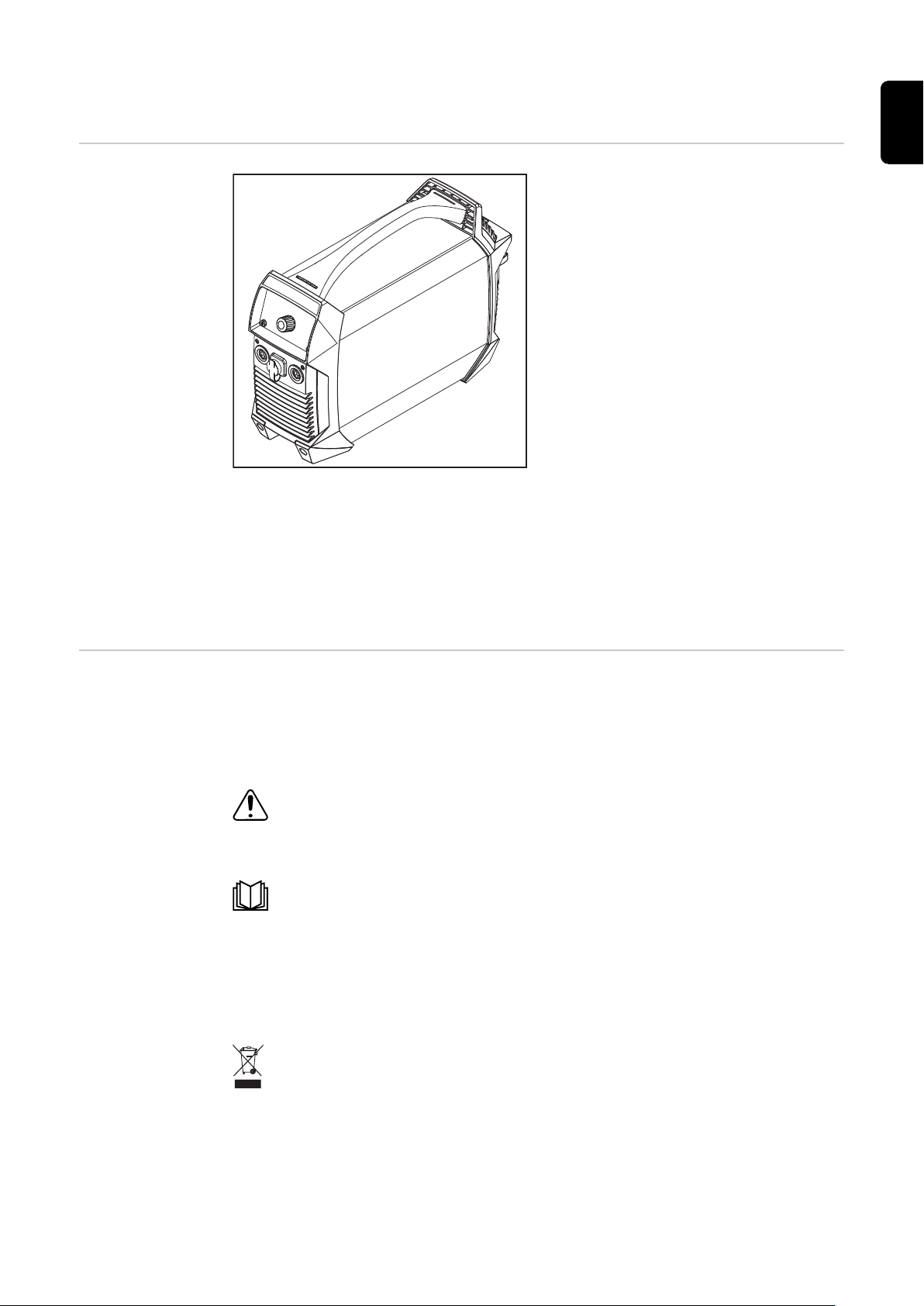
Device concept The power source has the following
properties:
Operation without mains electri-
-
city
Compact dimensions
-
Robust plastic housing
-
Extremely reliable even under
-
harsh operating conditions
Carrying strap for easy transport
-
on construction sites, etc.
Protected controls
-
Connection sockets with bayonet
-
latch
During welding, an electronic regulator adapts the power source characteristic to
suit the welding electrode. The result is a lightweight and compact device with
excellent ignition and weld properties.
When cellulose electrodes (CEL) are used, a special operating mode can be selected to ensure perfect welding results.
EN
Warning notices
on the device
TIG welding with touchdown ignition greatly extends the range of applications.
The warning notices and safety symbols on the power source must not be removed or painted over. They warn against incorrect operation which can lead to
serious injury and damage.
Meaning of safety symbols on the device:
Risk of serious injury and damage due to incorrect operation.
Do not use the functions described here until you have fully read and understood
the following documents:
these operating instructions
-
all the operating instructions for the system components of the power
-
source, especially the safety rules
Do not dispose of used devices with domestic waste. Dispose of them according
to the safety rules.
27

Application
areas
MMA welding TIG welding
28

Using rechargeable devices
EN
Safety
WARNING!
Danger due to improper handling of the lithium-ion battery.
This can result in severe injury or damage to property.
Never expose the power source to naked flames. Excessive heat can cause
▶
the battery to explode or burst.
Do not open the power source or remove the battery. If the battery becomes
▶
damaged due to improper handling, poisonous substances can escape which
may be harmful to health.
Do not drop the power source into water. This can cause a short circuit, even
▶
if the power source is switched off. This in turn can cause the battery to become hot, ignite or burst.
WARNING!
Danger due to incorrect operation and incorrectly performed work.
This can result in severe injury or damage to property.
Do not open the power source.
▶
The power source may only be opened by a Fronius service technician.
▶
If you need a replacement battery, hand the power source over to a Fronius
▶
Service Partner.
Storage and
transport
Service life of
the battery
When storing or transporting the power source, observe the environmental conditions in the Technical data section from page 66.
Particularly if the power source is stored for long periods of time, observe the
following points:
Only store the power source when it is charged. The state of charge should
-
ideally be between 50 and 80%
Optimum storage temperature: 0 °C to +20 °C (+32 °F to +68 °F)
-
Recharge the power source at least every six months
-
When transporting the power source, observe the relevant national guidelines.
Note the following safety data for transport:
Dangerous goods class: 9
-
Classification code: M4
-
Packaging group: II
-
NOTE!
The service life of the battery is dependent entirely upon how it is handled.
The way in which the battery is operated and stored and the conditions under
which this occurs are therefore extremely important.
The intelligent functions of the power source (see section Battery protection
functions from page 31) play a significant role in increasing the service life of
the battery.
29

However, the user must observe the following key points in order to guarantee
maximum battery life:
Recharge the battery after every discharge
-
Do not wait until the battery is completely discharged before recharging it.
Protect the power source from extreme influences
-
Optimal environmental conditions for operation:
-
Temperature: +15 °C to +25 °C (+59 °F to +77 °F)
-
Humidity: 50 %
-
Surrounding air is free from dust and corrosive vapours or gases
-
Charge power source regularly when not in use
-
Check power source at least every 6 months and recharge if necessary
-
30

Battery protection functions
General The battery protection functions serve to:
Increase the service life of the battery
-
Protect the battery from long-term damage
-
Ensure the reliability of the power source
-
EN
Deep discharge
protector
Automatic
switch-off
The power source has a deep discharge protector to warn the user if the state of
charge of the battery is too low. If this is the case, the power source switches off.
Function of the deep discharge protector:
When the battery capacity is exhausted
-
-
-
-
The power source switches off automatically after three seconds
-
Danger due to prolonged storage of the battery in a discharged state.
This can damage the battery.
If the deep discharge protector is triggered, charge the power source imme-
▶
diately!
Automatic switch-off avoids unnecessary power consumption, thereby extending
the effective period of operation with one battery charge.
If the power source is not operated for a specific length of time, it switches off
automatically.
all segments of the battery capacity indicator flash
"Lo" is shown on the display
welding is no longer possible
CAUTION!
To reactivate the power source, press the On/Off button for at least two seconds.
NOTE!
The factory setting for the automatic switch-off time is 15 minutes (if no welding is performed for 15 minutes, the power source switches off automatically).
This value can be changed in the Setup menu using the tSd parameter.
31

Temperature
monitoring
Temperature monitoring prevents the battery from being charged or discharged
if the temperature of the battery is outside the permitted temperature range.
The battery charger has an internal temperature management function
From 30 °C: Protection against overheating of the charger by automatic re-
-
duction of the power (derating)
From 45 °C: Only standard charging possible to increase battery life
-
From 70 °C: Power source switched off
-
Charging is not possible below 0 °C. Welding is conditionally possible de-
-
pending on the current level.
Two additional sensors directly on the power module
-
Undertemperature
If the battery falls below the permitted temperature range, neither welding nor
charging is possible.
Overcharging
protection
Overtemperature
Charging is only possible again at a battery temperature of less than +45 °C.
If the battery exceeds the permitted temperature range:
the temperature indicator lights up and „hot“ is shown on the display
-
neither welding nor charging is possible until the temperature indicator goes
-
out (when the battery has cooled down)
Once the battery has been fully charged, the charger turns off automatically and
switches to conservation charging mode.
More information on how the battery charger and the individual operating modes
work can be found in the charger description on page 69.
32

Before commissioning
EN
Safety
Danger from incorrect operation and work that is not carried out properly.
This can result in serious personal injury and damage to property.
▶
▶
▶
Proper use The power source is intended exclusively for MMA welding and TIG welding.
The integrated battery must only be charged with the Fronius ActiveCharger 1000.
Any other use is deemed improper.
The manufacturer is not liable for damage resulting from such use.
Proper use also includes:
-
-
-
WARNING!
All the work and functions described in this document must only be carried
out by technically trained and qualified personnel.
Read and understand this document in full.
Read and understand all safety rules and user documentation for this device
and all system components.
carefully reading these operating instructions
following all the instructions and safety rules in these operating instructions
performing all stipulated inspection and maintenance work
Setup regulations
WARNING!
Danger from machines toppling over or falling.
This can result in serious personal injury and damage to property.
Set up the device securely on an even, solid surface.
▶
Check all screw connections are tightly fastened after installation.
▶
The device is tested to IP 23 protection, meaning:
Protection against penetration by solid foreign bodies with diameters > 12.5
-
mm (0.49 in.)
Protected against spraywater at any angle up to 60° to the vertical
-
Cooling air
The device must be set up in such a way that cooling air can flow freely through
the slots in the front and rear panels.
Dust
Ensure that metallic dust is not sucked into the system by the fan, when carrying
out grinding for example.
Outdoor operation
The device can be set up and operated outdoors in accordance with IP23 degree
of protection. Avoid direct wetting (e.g. from rain).
Power connection
The device is designed to be connected to the mains using the Fronius ActiveCharger 1000 only (= hybrid mode, see Operating modes on page 77).
33

Before starting
for the first time
NOTE!
No warranty claims will be entertained if the device is operated with other chargers.
-
If the battery is fully charged:
-
-
-
Once connected, the battery capacity indicator on the power source
flashes to indicate the current state of charge; the battery is being charged
The COMPLETED indicator lights up on the charger
On the power source, all segments of the battery capacity indicator are
lit
The power source can be put into operation
34

Control elements and connections
(1)
(2)
(3)
(4)
(5)
(6)
(7)
(8)
EN
Safety
Connections and
mechanical components
WARNING!
Danger from incorrect operation and work that is not carried out properly.
This can result in serious personal injury and damage to property.
All the work and functions described in this document must only be carried
▶
out by technically trained and qualified personnel.
Read and understand this document in full.
▶
Read and understand all safety rules and user documentation for this device
▶
and all system components.
As a result of software updates, you may find that there are functions available
on your device that are not described in these Operating Instructions, or vice
versa.
Certain illustrations may also differ slightly from the actual controls on your
device, but these controls function in exactly the same way.
(1) (-) current socket
with bayonet latch
(2) TMC connection (TIG Multi Connector)
(3) (+) current socket
with bayonet latch
(4) Carrying strap
(5) Cable strap
for holding the mains cable and the welding power-leads
Do not use to move the device!
(6) Charger connection
(7) Air filter
(8) Shielding gas connection
35

The use of the current connections depends on the welding process:
MMA welding (depending on electrode type)
-
(+) current socket for electrode holder or grounding cable
(-) current socket for electrode holder or grounding cable
TIG welding
-
(+) current socket for grounding cable
(-) current socket for welding torch
TMC connection for control connection on the Fronius welding torch
36

Control panel
(10)
(8)
(7)
(3)
(4)
(5)
(6)
(11)
(9)
(1)
(2)
(1) Setting value indicator
shows which setting value is selected:
-
-
-
-
Arc-force dynamic
Welding current
SoftStart / HotStart function
TIG pulsing / pulse welding
EN
(2) Unit indicator
shows the unit of the value that is currently being changed using the
adjusting dial (8):
-
-
-
-
Percent
Voltage (volts)
Frequency (Hertz)
Time (seconds)
(3) Battery capacity indicator
shows the state of charge of the battery:
-
-
-
-
-
Battery fully charged
Battery capacity 75 %
Battery capacity 50 %
Battery capacity 25 %
Battery discharged Charge the battery now!
shows the operating mode:
lights up in the following situations:
-
in pure welding mode
-
in conservation charging mode
-
a bar also flashes in the following operating modes:
-
charging
-
quick charging
-
hybrid mode
-
(4) Display
(5) Welding process indicator
shows which welding process is selected:
-
-
-
-
MMA welding
MMA welding with Cel electrode
TIG welding
reserved for special programs
37

(6) Welding process button
for selecting the welding process
(7) On/Off button
for switching the power source on and off.
The button must be pressed for at least two seconds before it responds
(to protect against accidental operation)
(8) Adjusting dial
(9) TAC indicator
lights up when the tacking function is activated
(only possible on TIG devices during the TIG welding process)
(10) Setting value button
for selecting the desired setting value (1)
(11) Status indicators
display various operating modes of the power source:
-
-
-
-
VRD - lights up if the (optional) VRD safety device is present
and the reduced safety voltage is present at the welding sockets
Setup - lights up in Setup mode
Temperature - power source outside the permitted temperat-
ure range
Error - see also Troubleshooting from page 61
38

MMA welding
EN
Preparatory
work
1
2
3
4
5
6
Press the On/Off button for at least two seconds to turn off the power
source
the indicators go out
-
Plug the grounding cable into the (+) or (-) current socket depending on
which type of electrode is to be used and turn it clockwise to latch it in place
Use the other end of the grounding cable to establish a connection to the
workpiece
Plug the electrode holder into the (+) or (-) current socket depending on
which type of electrode is to be used and turn it clockwise to latch it in place
Insert the rod electrode into the electrode holder
WARNING!
Danger from electrical current.
This can result in serious personal injury and damage to property.
As soon as the power source is switched on, the electrode in the elec-
▶
trode holder is live. Make sure the electrode does not touch any persons
or electrically conductive or earthed parts (e.g. the housing, etc.).
Press the On/Off button for at least two seconds to turn on the power
source
-
-
the welding current indicator lights up
the display shows the specified welding current
MMA welding
SoftStart / HotStart function
1
2
3
This function is used to set the starting current.
Setting range: 0 - 200%
Operating principle:
At the start of the welding process, the welding current is reduced (SoftStart) or
increased (HotStart) for 0.5 seconds, depending on the setting.
The change is shown as a percentage from the set welding current.
Use the welding process button to select one of the following processes:
MMA welding - the MMA welding indicator lights up after selection
MMA welding with Cel electrode - the MMA welding with Cel elec-
trode indicator lights up after selection
Press the setting value button until
the welding current indicator lights up
Select the amperage using the adjusting dial
Power source is ready for welding
-
The duration of the starting current can be changed in the Setup menu using the
Hti parameter, see Parameters for MMA welding on page 50.
39

Setting the starting current:
I (A)
t
90A
0,5 s 1 s 1,5 s
120A
1
Press the setting value button until
the SoftStart / HotStart indicator lights up
2
Turn the adjusting dial until the desired value is reached
Power source is ready for welding
-
NOTE!
The maximum HotStart current is limited to 180 A.
Examples:
(set welding current = 100 A)
-
100% Starting current = 100 A Function deactivated
-
80% Starting current = 80 A SoftStart
-
135% Starting current = 135 A HotStart
-
200% Starting current = 180 A HotStart (maximum current limit
reached!)
Features of SoftStart function:
Reduced pore formation with cer-
-
tain electrode types
Example of HotStart function
Features of HotStart function:
Improved ignition properties, even
-
when using electrodes with poor
ignition properties
Better fusion of the base material
-
during the start-up phase, meaning
fewer cold-shut defects
Largely prevents slag inclusions
-
40

Arc-force dynamic
To obtain optimum welding results, it will sometimes be necessary to adjust the
arc-force dynamic.
Setting range: 0 - 100 (corresponds to 0 - 200 A current increase)
Operating principle:
At the moment of droplet transfer or in the event of a short circuit, the amperage is briefly increased in order to obtain a stable arc.
If the rod electrode threatens to sink into the weld pool, this measure prevents
the weld pool solidifying, as well as preventing a prolonged short-circuit of the
arc. This largely prevents the rod electrode from sticking.
Setting the arc-force dynamic:
EN
1
Press the setting value button until
the arc-force dynamic indicator lights up
2
Turn the adjusting dial until the desired correction value is reached
Power source is ready for welding
-
NOTE!
The maximum arc-force dynamic current is limited to 180 A.
Examples:
Arc-force dynamic = 0
-
arc-force dynamic deactivated
-
soft, low-spatter arc
-
Arc-force dynamic = 20
-
arc-force dynamic with 40 A current increase
-
harder, more stable arc
-
Set welding current = 100 A / arc-force dynamic = 60
-
arc-force dynamic theoretically with 120 A current increase
-
actual increase is just 80 A as the maximum current limit has been
-
reached!
41

TIG modes
I
t
I-1
GPo
GPr
1 2 3
tdowntup
Symbols and
their explanations
Pull back and hold the torch trigger
Release the torch trigger forwards
Push forward and hold the torch trigger
Release the torch trigger backwards
Adjustable parameters:
GPo: Gas post-flow time
-
I-S: Starting-current phase - the temperature is raised gently at low welding
-
current, so that the filler metal can be positioned correctly
I-E: Final current phase - to prevent crater cracks or cavitations
-
I-1: Main current phase (welding-current phase) - uniform thermal input into
-
the base material, whose temperature is raised by the continuous heat
I-2: Reduced current phase - intermediate lowering of the welding current in
-
order to prevent any local overheating of the base material
Fixed parameters:
GPr: Gas pre-flow time
-
tup: UpSlope phase - the welding current is continually increased
-
Duration = 0.5 seconds
t
-
: DownSlope phase - the welding current is continually decreased
down
Duration = 0.5 seconds
tS: Starting current duration
-
tE: Final current duration
-
2-step mode See the section on page for details on how to activate 2-step mode.
Place the tungsten electrode onto the workpiece and then pull the torch trig-
1
ger back and hold => shielding gas flows
Raise the tungsten electrode => arc ignites
2
42

Release torch trigger => end of welding
I
t
I-1
GPr
I-S
I-E
I-2
GPo
I-1
tdown tets
1 2 3 4 5 6 7
tup
3
4-step mode See the section on page for details on how to activate 4-step mode.
4-step mode with intermediate lowering I-2
Intermediate lowering means that the welder uses the torch trigger during the
main current phase to lower the welding current to the specified reduced current
I-2.
EN
Place the tungsten electrode onto the workpiece and then pull the torch trig-
1
ger back and hold => shielding gas flows
Raise the tungsten electrode => start of welding with starting current I-S
2
Release torch trigger => welding with main current I-1
3
Push forward and hold the torch trigger => activation of intermediate lower-
4
ing with reduced current I-2
Release torch trigger => welding with main current I-1
5
Pull back and hold the torch trigger => lowering to final current I-E
6
Release torch trigger => end of welding
7
43

TIG welding
max. 5 bar
(72 psi)
General
Connecting the
gas cylinder
NOTE!
Do not use pure tungsten electrodes (colour-coded green) if the TIG welding
process has been selected.
WARNING!
Danger from falling gas cylinders.
This can result in severe personal injury and damage to property.
Place gas cylinders on a solid, level surface so that they remain stable. Se-
▶
cure gas cylinders to prevent them from falling over.
Observe the safety rules of the gas cylinder manufacturer.
▶
1
2
Preparation
44
1
2
3
4
5
Press the On/Off button for at least two seconds to turn off the power
source
the indicators go out
-
Plug the TIG welding torch into the (-) current socket and turn it clockwise to
latch it in place
Plug the TIG Multi Connector plug of the TIG welding torch into the TMC
connection of the power source
Set up the welding torch in accordance with the welding torch Operating Instructions
Plug the grounding cable into the (+) current socket and turn it clockwise to
latch it in place

Use the other end of the grounding cable to establish a connection to the
6
workpiece
WARNING!
Danger from electric shocks.
This can result in serious injury and damage to property.
As soon as the power source is switched on, the electrode in the welding
▶
torch is live. Make sure the electrode does not touch any persons or electrically conductive or earthed parts (e.g. the housing, etc.).
EN
Setting the gas
pressure
7
Press the On/Off button for at least two seconds to turn on the power
source
-
-
Welding torch with torch trigger
(and TIG Multi Connector plug)
the welding current indicator lights up
the display shows the specified welding current
Welding torch with torch trigger (and
TIG Multi Connector plug):
Press the torch trigger
1
shielding gas flows
-
Set the desired gas flow rate on
2
the pressure regulator
Release the torch trigger
3
TIG welding
1
Select TIG welding with the welding process button
the TIG welding indicator lights up
2
Press the setting value button until
the welding current indicator lights up
3
Adjust the welding current using the adjusting dial
When using a welding torch with a torch trigger and TIG Multi Connector plug
(with 2-step mode factory setting):
Place the gas nozzle down on the ignition location, ensuring there is a gap of
4
approx. 2 to 3 mm (5/64 to 1/8 in.) between the tungsten electrode and the
workpiece Gap exists
Gradually tilt the welding torch up until the tungsten electrode touches the
5
workpiece
Pull back and hold the torch trigger
6
Shielding gas flows
-
Raise the welding torch and rotate it into its normal position
7
The arc ignites
-
45

Carry out welding
4 6 7
1 2 3 4 5
+
8
TIG Comfort
Stop
For more information on activating and setting the TIG Comfort Stop function
see Parameters for TIG welding from page 52.
Function and application of TIG Comfort Stop:
Welding
1
During welding, raise the welding torch
2
The arc length is increased significantly
-
Lower the welding torch
3
The arc length is decreased significantly
-
This triggers the TIG Comfort Stop function
-
Keep the welding torch at the same height
4
The welding current continually decreases (downslope) until the arc goes
-
out
Wait for the gas post-flow time to finish and lift the welding torch away from
5
the workpiece
46

t
tdown
I
Max. A
70 A
(1)
(2)
1 2
3 4 5+
Welding current and gas flow curve with TIG Comfort Stop function activated
(1) Gas pre-flow
(2) Gas post-flow
EN
Downslope:
The downslope time t
Gas post-flow:
The gas post-flow can be changed in the Setup menu via the "GPo" value, see
Parameters for TIG welding on page 52.
is 0.5 seconds and cannot be adjusted.
down
47

TIG pulsing TIG pulsing is TIG welding with a pulsing welding current. It is used for out-of-
1/F-P
I-P
I-G
I
t
t
up
t
down
I-S
I-E
dcY
position welding of steel pipes or when welding thin sheets.
In these applications, the welding current set at the start of welding is not always
ideal for the whole welding process:
if the amperage is too low, the base material will not melt sufficiently
-
if overheating occurs, the liquid weld pool may drip
-
Setting range: 0.5 - 990 Hz
Operating principle:
A low base current I-G rises steeply to the significantly higher pulse current I-P
and, depending on the set dcY (duty cycle) time, drops back to the base current
I-G.
This results in an average for the main current of I-1.
During TIG pulsing, small sections of the welding location melt quickly and then
solidify again quickly.
Activating TIG pulsing / setting the pulse frequency:
1
Press the setting value button until
the TIG pulsing indicator lights up
2
Turn the adjusting dial until the desired frequency value (Hz) is reached
power source is ready for welding
-
TIG pulsing - welding current curve
48
Legend: I-P Pulse current
I-S Starting current F-P Pulse frequency *)
I-E Final current dcY Duty cycle
t
up
t
Down
*) (1/F-P = time interval between two pulses)
UpSlope I-G Base current
DownSlope I-1 Main current

Tacking function Activating and setting the tacking function is described in the Tacking function
tAC
I-1
I
t
t
up
t
down
I-S
I-E
(tACking) section on page 53.
The tacking function is only available for the TIG DC welding process.
When a time period is specified for the tAC (tacking) setup parameter, the
-
tacking function is assigned to all operating modes
The basic operating sequence of each of these modes remains unchanged
-
During the specified period, there is a pulsed welding current that makes the
-
weld pool run together better when two components are being tacked.
EN
Tacking function - welding current curve
Key:
tAC Duration of pulsed welding current for the tacking process
I-S Starting current
I-E Final current
t
up
t
Down
UpSlope
Downslope
I-1 Main current
NOTE!
The following points apply to the pulsed welding current:
The power source automatically regulates the pulsing parameters depending
▶
on the specified main current I-1
There is no need to set any pulsing parameters
▶
The pulsed welding current begins
after the end of the starting-current phase I-S
-
with the UpSlope phase t
-
up
After the tAC time has elapsed, welding continues at a constant welding current,
and any pulsing parameters that may have been set are available.
49

The Setup menu
Accessing the
Setup menu
Changing welding parameters
1
Use the welding process button to select the process for which the Setup
parameters are to be changed:
MMA welding
MMA welding with Cel electrode
TIG welding
2
MMA welding
-
MMA welding with Cel electrode
-
TIG welding
-
+ Press the setting value and welding process buttons together
After releasing the buttons, the code for the first parameter in the Setup
-
menu is displayed
Turn the adjusting dial to select the required parameter
1
Exiting the
Setup menu
Parameters for
MMA welding
Press the adjusting dial to display the preset value of the parameter
2
Turn the adjusting dial to change the value
3
the new value becomes effective immediately
-
exception: when restoring the factory settings, press the adjust-
-
ing dial after changing the value to activate the new value.
Press the adjusting dial to return to the list of parameters
4
1
Press the setting value or
welding process button to exit the Setup menu
50

Starting current duration
0,1 - 1,5 seconds
for the SoftStart / HotStart function
Factory setting: 0.5 seconds
Anti-Stick
On / OFF
When the anti-stick function is active, the arc is extinguished after 1.5 seconds in
the event of a short circuit (sticking of the electrode)
Factory setting: ON (activated)
Break voltage (U cut off)
25 - 80 Volts
Used to specify at which arc length the welding process is to be completed.
The welding voltage increases as the length of the arc increases. The arc is extinguished when it reaches the voltage specified here.
Factory setting: 45 volts
EN
Software version
The full version number of the currently installed software is spread across a
number of displays and can be retrieved by turning the adjusting dial.
Automatic switch-off (time Shut down)
300 - 900 Seconds / OFF
If the power source is not operated for the specified length of time, it switches
off automatically.
Factory setting: 900 seconds
Factory setting (FACtory)
The power source can be reset to its factory settings here.
no / YES / ALL
Cancel reset
-
Reset the parameters for the selected welding process to their factory set-
-
tings
Reset the parameters for all welding processes to their factory settings
-
Resetting of the selected value to its factory setting must be confirmed by pressing the adjusting dial.
51

Parameters for
TIG welding
Operating mode (trigger mode)
OFF / 2t / 4t
Operation using welding torch without a torch trigger
-
2-step mode
-
4-step mode
-
Factory setting: 2t
Starting current (I-Start)
1 - 200 percent
This parameter is only available in 4-step mode (tri = 4t).
Factory setting: 50 %
Reduced current
1 - 200 percent
This parameter is only available in 4-step mode (tri = 4t).
Factory setting: 50 %
Final current (I-End)
1 - 100 percent
This parameter is only available in 4-step mode (tri = 4t).
Factory setting: 50 %
Gas post-flow time (Gas Post flow)
0.2 - 9.9 seconds
Specified period during which gas flows at the end of welding.
Factory setting: 9.9 seconds
Comfort Stop Sensitivity (Comfort Stop Sensitivity)
0.3 - 2.0 V / OFF
This parameter is only available when the tri parameter is set to OFF.
Factory setting: OFF
For details see the TIG Comfort Stop section from page 46.
52

Break voltage (U cut off)
12 - 35 V
Used to specify at which arc length the welding process is completed. The welding voltage increases as the length of the arc increases. The arc is extinguished
when it reaches the voltage specified here.
This parameter is only available when the tri and CSS parameters are set to OFF.
Factory setting: 15 volts
Tacking function (tACking)
0.1 - 9.9 seconds / OFF
Factory setting: ON
For details see the Tacking function section on page 49.
Software version
The full version number of the currently installed software is spread across a
number of displays and can be retrieved by turning the adjusting dial.
EN
Automatic shutdown (time Shut down)
300 - 900 seconds / OFF
If the power source is not operated for the specified length of time, it switches
off automatically.
Factory setting: 900 seconds
Factory setting (FACtory)
no / YES / ALL
The power source can be reset to its factory settings here.
cancel reset
-
reset the parameters for the selected welding process to their factory set-
-
tings
reset the parameters for all welding processes to their factory settings
-
Resetting of the selected value to its factory setting must be confirmed by pressing the adjusting dial.
53

VRD safety device (optional)
General VRD is an additional safety device that prevents, as far as possible, output
voltages that may pose a danger to persons.
VRD = Voltage Reduction Device.
Function
VRD is active
VRD is not active
NOTE!
The welding circuit resistance is greater than the minimum human body resistance (greater than or equal to 200
Ohm):
VRD is active
-
Open circuit voltage is limited to
-
14 V
-
-
The welding circuit resistance is less
than the minimum human body resistance (less than 200 Ohm):
-
-
-
-
The VRD indicator lights up
Example: no risk ensues if both
welding sockets are touched accidentally at the same time.
VRD is inactive
Output voltage not limited in order
to ensure sufficient welding power
The VRD indicator does not light
up
Example: Start of welding
Within 0.
3 seconds of the end of welding:
VRD is active again
▶
The output voltage is limited to 14 V again
▶
54

Care and maintenance
EN
Safety
WARNING!
Danger from incorrect operation and work that is not carried out properly.
This can result in serious personal injury and damage to property.
All the work and functions described in this document must only be carried
▶
out by technically trained and qualified personnel.
Read and understand this document in full.
▶
Read and understand all safety rules and user documentation for this device
▶
and all system components.
WARNING!
Danger from electrical current.
This can result in serious personal injury and damage to property.
Before starting work, switch off all devices and components involved and dis-
▶
connect them from the grid.
Secure all devices and components involved so they cannot be switched back
▶
on.
After opening the device, use a suitable measuring instrument to check that
▶
electrically charged components (such as capacitors) have been discharged.
WARNING!
Danger from incorrect operation and work that is not carried out properly.
This can result in serious personal injury and damage to property.
Do not open the power source. The power source may only be opened by a
▶
Fronius service engineer.
If you need a replacement battery, hand the power source over to a Fronius
▶
Service Partner.
General Under normal operating conditions, the device requires only a minimum of care
and maintenance. However, it is vital to observe some important points to ensure
the device remains in a usable condition for many years.
At every startup
Check the charging lead, welding torch/electrode holder, welding power-lead
-
and grounding (earthing) connection for damage. Replace any damaged components
Check that there is an all-round clearance of 0.5 m (1 ft. 8 in.) around the
-
power source to ensure that cooling air can flow in and out freely
NOTE!
Air inlets and outlets must never be covered, not even partially.
55

Every 2 months Clean the air filter (if fitted):
1
56

Disposal
General Dispose of in accordance with the applicable national and local regulations.
Always dispose of the device separately from the installed battery.
The following section explains how to remove the battery.
EN
Safety
WARNING!
Danger due to incorrect operation and incorrectly performed work.
This can result in serious injury and damage to property.
All the work and functions described in this document must only be carried
▶
out by trained and qualified personnel.
Read and understand this document.
▶
Read and understand all the Operating Instructions for the system compon-
▶
ents, especially the safety rules.
WARNING!
Danger from electric current.
An electric shock can be fatal.
Switch off the power source.
▶
Disconnect the power source from the battery charger.
▶
Ensure that the power source remains disconnected from the battery char-
▶
ger until all work has been completed.
After opening the device, use a suitable measuring instrument to check that
▶
electrically charged components (such as capacitors) have been discharged.
57

Removing the re-
1
2
1
1
1
2
2
2
2
1
1
2
1
1
chargeable battery pack
NOTE!
The following steps on removing the rechargeable battery pack must only be
used when disposing of the device!
If the rechargeable battery pack needs to be repaired or replaced, contact
▶
After-Sales Service.
NOTE!
Before removing the rechargeable battery pack, the power source must be disconnected from the battery charger!
Ensure that the power source is completely discharged.
▶
1
Remove the control panel
3
2
Disconnect the (+) power cable from the rechargeable battery pack, remove 2 TX25 screws
4
Remove 2 TX25 screws, remove device feet at
the front
58
Remove 2 TX25 screws, remove the cover

3
2
2
1
1
5
3
1
2
2
1
1
6
EN
Remove 2 TX25 screws, remove device feet, fold
rear to one side
7
Press front and rear outwards, remove device casing
Press front and rear outwards, remove carrying
handle
CAUTION!
Fire hazard due to short circuit of the battery!
If the battery is short-circuited, sparks may be generated and the battery may
catch fire.
After terminating the (-) power cable, insulate it well (e.g. wrap it with insulat-
▶
ing tape)!
59

1
8
2
2
2
2
2
2
3
1
9
Remove TX25 screw and terminate (-) power
cable of the rechargeable battery back;
IMPORTANT! Insulate the terminated cable lug
well!
Dispose of the device and rechargeable battery pack separately according to
10
Disconnect 16-pin connector X1 from the battery pack, remove 6 TX 20 screws, remove the
rechargeable battery pack
the local guidelines
60

Troubleshooting
EN
Safety
WARNING!
Danger from incorrect operation and work that is not carried out properly.
This can result in serious personal injury and damage to property.
All the work and functions described in this document must only be carried
▶
out by technically trained and qualified personnel.
Read and understand this document in full.
▶
Read and understand all safety rules and user documentation for this device
▶
and all system components.
WARNING!
Danger from electrical current.
This can result in serious personal injury and damage to property.
Before starting work, switch off all devices and components involved and dis-
▶
connect them from the grid.
Secure all devices and components involved so they cannot be switched back
▶
on.
After opening the device, use a suitable measuring instrument to check that
▶
electrically charged components (such as capacitors) have been discharged.
WARNING!
Indicated errors
Danger from incorrect operation and work that is not carried out properly.
This can result in serious personal injury and damage to property.
Do not open the power source. The power source may only be opened by a
▶
Fronius service engineer.
If you need a replacement battery, hand the power source over to a Fronius
▶
Service Partner.
Overtemperature
"hot" appears on the display, the temperature indicator lights up
+
Cause:
Remedy:
Undertemperature
"cold" appears as scrolling text on the display, the temperature indicator lights
up
Device is too hot
Check/reduce ambient temperature, allow power source to cool
down
+
Cause:
Remedy:
Device temperature too low
Check/increase ambient temperature, operate the power source in a
warmer environment
For more information see the Environmental conditions section on
page 66
61

Deep discharge protector
"Lo" appears in the display, the "Battery capacity" indicator flashes
+
Service messages
Cause:
Remedy:
Danger due to prolonged storage of the battery in a discharged state.
This can damage the battery.
If the deep discharge protector is triggered, charge the power source
▶
promptly!
When E and a 2 digit error number appear in the display (e.g. E02) and the "Error"
indicator lights up, this is an internal power source service code.
Example:
It is also possible that several error numbers are present. These appear when
turning the adjusting dial.
Battery discharged, deep discharge protection has been activated
Charge the battery now
Battery operation is possible again above 25% capacity
CAUTION!
Make a note of the error numbers shown in the display, and of the serial number
and configuration of the power source, and contact our after-sales service team
with a detailed description of the error.
E02 / E03 / E05 / E06
Cause:
Remedy:
E07 / E72
Cause:
Remedy:
E09 / E10
Cause:
Remedy:
E11
Cause:
Remedy:
E12 / E13 /E14
Cause:
Remedy:
Internal temperature sensor fault on ACCUPLT / ACCUPLT-TIG PC
board
Contact after-sales service
Internal supply voltage 15 V outside the valid range
Contact After-Sales Service
Load too high on power source current sockets
Use power source correctly (welding)
No communication with the control panel
Contact after-sales service
Internal error on ACCUPLT / ACCUPLT-TIG PC board
Contact after-sales service
62

E16
Cause:
Remedy:
E18
Cause:
Remedy:
E19 / E22 / E30 / E53 / E83
Cause:
Remedy:
E23
Cause:
Remedy:
Communication error between battery and ACCUPLT / ACCUPLTTIG PC board
Contact after-sales service
Wrong firmware (software) has been loaded
Contact after-sales service
Battery fault
Contact After-Sales Service
A voltage of > 113 V DC has been measured on the current sockets
Contact After-Sales Service
EN
No function
The power source cannot be switched on
Cause:
Remedy:
Cause:
Remedy:
Battery is not charged
Power source is connected to the charger, charger is connected to the mains, no
charging indicator on the power source
Cause:
Remedy:
Cause:
Remedy:
Cause:
Remedy:
The battery has entered a state of deep discharge as it has been
stored for too long without being charged
Charge the battery now
Battery operation is possible again above 25% capacity.
If charging is no longer possible, contact After-Sales Service.
Control panel defective
Contact After-Sales Service
Device is too hot
Check/reduce ambient temperature, allow battery to cool down
Device temperature too low
Check/increase ambient temperature, disconnect and reconnect bat-
tery charger
Charging cable defective
Renew charging cable
63

No welding current
Power source is switched on, indicator for the selected welding process is lit
Cause:
Remedy:
Cause:
Remedy:
Cause:
Remedy:
No welding current
Power source is switched on, indicator for the selected welding process is lit,
overtemperature indicator lit
Cause:
Remedy:
Cause:
Remedy:
Cause:
Remedy:
Welding power-lead connections have been disconnected
Establish proper welding power-lead connections
Poor or no earth
Establish a connection to the workpiece
There is a break in the power cable in the welding torch or electrode
holder
Replace welding torch or electrode holder
Duty cycle exceeded - power source overloaded - fan running
Keep within duty cycle
Thermostatic automatic circuit breaker has been tripped
Wait until the power source comes back on automatically at the end
of the cooling phase
The fan in the power source is faulty
Contact After-Sales Service
Faulty operation
Cause:
Remedy:
Cause:
Remedy:
No welding current
Power source is switched on, indicator for the selected welding process is lit,
overtemperature indicator lit
Cause:
Remedy:
Poor ignition properties during MMA welding
Cause:
Remedy:
Cause:
Remedy:
Insufficient cooling air intake
Ensure adequate air supply
Air filter is dirty
Clean air filter
Power module error
Turn off the power source, then turn it on again.
If the error occurs frequently, contact After-Sales Service
Incorrect welding process selected
Select "MMA welding" or "MMA welding with Cel electrode" process
Starting current too low; electrode sticking during ignition
Increase starting current using HotStart function
64
Cause:
Remedy:
Starting current too high; electrode consumed too quickly during ignition or is generating a lot of spatter
Reduce starting current using SoftStart function

In some cases, arc breaks during welding
Cause:
Remedy:
Electrode (e.g. grooved electrode) voltage too high
If possible, use alternative electrode or a power source with more
welding power
EN
Cause:
Remedy:
Cause:
Remedy:
Rod electrode tends to stick
Cause:
Remedy:
Poor weld properties
(severe spattering)
Cause:
Remedy:
Cause:
Remedy:
Cause:
Remedy:
Comfort Stop Sensitivity (CSS) setting is too sensitive
Increase or deactivate the CSS value in the Setup menu
Break voltage (Uco) set too low
Increase break voltage (Uco) in Setup menu
Value of arc-force dynamic parameter (MMA welding) set too low
Increase value of arc-force dynamic parameter
Incorrect electrode polarity
Reverse electrode polarity (refer to manufacturer's instructions)
Poor grounding (earthing) connection
Fasten earthing clamps directly to workpiece
Setup parameters not ideal for selected welding process
Select the optimal settings in the Setup menu for the selected weld-
ing process
Tungsten electrode melting
Tungsten inclusions in base metal during the ignition phase
Cause:
Remedy:
Cause:
Remedy:
VRD does not light up even though no welding process is taking place
Cause:
Remedy:
Incorrect tungsten electrode polarity
Connect the TIG welding torch to the (-) current socket
Incorrect (or no) shielding gas
Use inert shielding gas (argon)
VRD option not present
or internal device fault
Contact after-sales service
65

Technical data
Environmental
conditions
Transport, storage or operation of the device outside the stipulated range will be
deemed improper. The manufacturer shall not be held liable for any damage
arising from such usage.
Ambient air temperature range:
During operation: -10 °C to + 40 °C (14 °F to 104 °F)
-
During transport: -20 °C to +55 °C (-4 °F to 131 °F)
-
Recommended temperature range during charging:
-
+ 4 °C to + 40 °C (+ 39.2 °F to + 104 °F)
Recommended temperature range during storage:
-
0 °C to + 20 °C (+ 32 °F to + 68 °F)
When placing in storage, the state of charge should ideally be at 50 - 80%
(corresponds to approx. 2 to 3 bars on the charging status indication).
Relative humidity:
Up to 50% at 40 °C (104 °F)
-
Up to 90 % at 20 °C (68 °F)
-
The surrounding air must be free from dust, acids, corrosive gases or substances,
etc.
Can be used at altitudes up to 2000 m (6561 ft.)
Explanation of
the term "duty
cycle"
Duty cycle (ED) is the proportion of time in a 10-minute cycle at which the device
may be operated at its rated output without overheating.
NOTE!
The ED values specified on the rating plate are based on an ambient temperature of 40 °C.
If the ambient temperature is higher, either the ED or output must be reduced
accordingly.
Example: Welding at 150 A at 60% ED
Welding phase = 60% of 10 minutes = 6 minutes
-
Cooling phase = remaining time = 4 minutes
-
After the cooling phase, the cycle begins again.
-
66

10 Min.6 Min.
150 A
0 Min.
0 A
4 Min.6 Min.
60 %
If the device is to be continuously operated without stopping:
Look in the technical data for a ED value of 100% for the current ambient
1
temperature.
Reduce the output or amperage in line with this value so that the device can
2
remain in use without observing a cooling phase.
EN
Technical data
Rated battery voltage 50.4 V
Charging current 10 A
Rapid charging current 18 A
Battery capacity 15 Ah
Battery type Li-ion
Standard charging 90 min.
Rapid charging 50 min.
Weld time Ø 2.5 mm Electrode 21 - 27 pcs
Ø 3.25 mm
Electrode 9 - 12 pcs
Welding current range Electrode DC 10 - 150 A
TIG DC 3 - 150 A
Welding current in hybrid mode (manual metal arc welding)
40 °C (104 °F)
40 °C (104 °F)
40 °C (104 °F)
18 % D.C.
25 % D.C.
100 % D.C.
1)
1)
1)
150 A
100 A
40 A
Welding current in hybrid mode (TIG welding)
40 °C (104 °F)
40 °C (104 °F)
40 °C (104 °F)
25 % D.C.
50 % D.C.
100 % D.C.
1)
1)
1)
150 A
100 A
65 A
Open circuit voltage 91 V
Reduced open circuit voltage
(only with VRD option)
14 V
67

Protection class IP 23
Type of cooling AF
Dimensions L x W x H 435 x 160 x 310 mm
17.1 x 6.3 x 12.2 in.
Weight 11.4 kg (25.1 lb)
Max. shielding gas pressure 5 bar (72 psi)
1)
D.C. = Duty cycle
68

Charger
69

70

General
xxxxxxxx
xxxxxxxx
4,010,341,xxx
In:
ActiveCharger 1000/230V
~230V 50/60Hz; 1100W
DC 58V/18A
A-4600 Wels
www.fronius.com
Protective class I
Out
MAX
:
IP 43S
Chr. No.
Part No.
EMC Emission
Class A
EN
Warning notices
on the device
A number of safety symbols can be seen on the charger's rating plate. The safety
symbols must not be removed or painted over.
Do not use the functions described here until you have fully read and understood
the following documents:
these operating instructions
-
all the operating instructions for the system components of the power
-
source, especially the safety rules
Possible sources of ignition, such as fire, sparks and naked flames, must be kept
away from the battery.
Ensure an adequate supply of fresh air during charging. Maintain a distance of at
least 0.5 m (19.69 in.) between battery and charger during the charging procedure.
Do not dispose of used devices with domestic waste. Dispose of them according
to the safety rules.
71

Warning notices
Entladezeit > 5 sek.
Discharge time > 5 sec.
Temps de décharge > 5 s
inside the device
An electric shock can be fatal. Do not open the device!
The housing must never be opened by anyone other than a Fronius-trained service engineer. The device must be disconnected from the mains before starting
any work with the housing open. A suitable measuring instrument must be used
to ensure that electrically charged components (e.g. capacitors) are fully discharged. Ensure that the device remains disconnected from the mains until all
work has been completed.
This warning sign is located inside the
device. It must NOT be removed or
painted over.
The discharge time of the capacitors is
approx. one minute.
Intended use The charger is designed to charge the power sources listed below. Any use above
and beyond this purpose is deemed improper. The manufacturer shall not be liable for any damage resulting from such use. Proper use also includes:
Carefully reading these Operating Instructions
-
Following all the instructions and safety rules in these Operating Instruc-
-
tions
WARNING!
Charging any other devices can cause serious injury or damage, and is therefore
prohibited.
The following power sources may be charged:
Fronius AccuPocket 150/400
-
Fronius AccuPocket 150/400 TIG
-
Fronius Ignis 150 B /750
-
The charger is intended solely for commercial use.
72

Before commissioning
EN
Mains connection
Generatorpowered operation
The rating plate, which is located on the housing, contains information about the
permitted mains voltage. The device is designed for this mains voltage only. For
details on the required fuse protection for the mains lead, see theTechnical data
section on page 80. If there is no mains cable or mains plug on your version of
the appliance, fit one that conforms to national standards.
CAUTION!
Danger due to insufficiently dimensioned electrical installations.
This can result in serious damage to property.
The mains lead and its fuse must be dimensioned to suit the local power sup-
▶
ply.
Read the technical data on the rating plate.
▶
The charger is completely generator-compatible, provided the maximum apparent power delivered by the generator is at least 2 kVA.
This also applies if the generator in question is an inverter.
NOTE!
The voltage delivered by the generator must never exceed the upper or lower
limits of the mains voltage tolerance range.
Setup regulations
Details on the mains voltage tolerance can be found in the Technical data section
on page 80.
WARNING!
Danger from machines toppling over or falling.
This can result in serious personal injury and damage to property.
Set up the device securely on an even, solid surface.
▶
Check all screw connections are tightly fastened after installation.
▶
The device is tested to IP40 protection, meaning:
Protection against penetration by solid foreign bodies with diameters > 1.0
-
mm (0.04 in.)
Protection against spraywater at any angle up to 60° to the vertical when fan
-
is not running.
Dust
Ensure that metallic dust is not sucked into the system by the fan, when carrying
out grinding for example.
Outdoor operation
The device can be set up and operated outdoors in accordance with IP40 degree
of protection. Avoid direct wetting (e.g. from rain).
73

Space require-
100 mm
3.9 inch
168 mm
6.6 inch
275 mm
10.8 inch
ments
If the charger is installed in a switch cabinet (or a similar sealed area), then
forced-air ventilation must be provided to ensure adequate heat dissipation.
There should be an all-round clearance of 10 cm (3.9 in.) around the charger.
74

Control elements and connections
(1) (2) (3)
CHARGING
ActiveCharger 1000
QUICK CHA RGING
QUICK
CHARGE
QUICK
CHARGE
COMPLETED
(5)(4)
(1)
(2)
(3)
(6)
EN
Safety
Connections and
components
WARNING!
Danger from incorrect operation and work that is not carried out properly.
This can result in serious personal injury and damage to property.
All the work and functions described in this document must only be carried
▶
out by technically trained and qualified personnel.
Read and understand this document in full.
▶
Read and understand all safety rules and user documentation for this device
▶
and all system components.
As a result of software updates, you may find that there are functions available
on your device that are not described in these Operating Instructions, or vice
versa.
Certain illustrations may also differ slightly from the actual controls on your
device, but these controls function in exactly the same way.
(1) Mains cable
for connection to the mains
(2) Connection P1 - charging lead
socket
to plug in the charging cable for
connection to the power source
Control panel
(3) Control panel
(1) CHARGING indicator (green)
Charging in progress
(2) QUICK CHARGING indicator
(green)
Quick charging in progress
(3) COMPLETED indicator (green)
Power source fully charged
(4) Error indicator (red)
See section Troubleshooting on
page 79
(5) Mains indicator (green)
Mains supply voltage available
(6) QUICK CHARGE button
Starts and stops quick charging
75

Start-up
Safety
Commissioning
WARNING!
Danger from incorrect operation and work that is not carried out properly.
This can result in serious personal injury and damage to property.
All the work and functions described in this document must only be carried
▶
out by technically trained and qualified personnel.
Read and understand this document in full.
▶
Read and understand all safety rules and user documentation for this device
▶
and all system components.
-
2
If the battery is fully charged:
-
-
NOTE!
The system includes the following features for maximum user-friendliness:
▶
▶
Once connected, the battery capacity indicator on the power source
flashes to indicate the current state of charge; the battery is being charged
Select Quick Charge mode if required - details on the available operating
modes can be found in the following section
The COMPLETED indicator lights up on the charger
On the power source, all segments of the battery capacity indicator are
lit
It does not matter in what order the devices are connected to the mains
The power source can even be connected to the charger while it is in use
76

Operating modes Charging
Starts automatically when the battery charger is connected to the power source
and the mains
EN
-
-
-
-
The CHARGING indicator is lit
Mains indicator lit
The power source is charged at optimum charging power
The charging characteristic of this mode maximises the service life of the
power source
-
When the COMPLETED indicator lights up, the power source is fully
charged and the battery charger switches to conservation charging mode
Quick charging
Activation:
Press the QUICK CHARGING button
1
-
-
-
-
The QUICK CHARGING indicator is lit
Mains indicator lit
The power source is charged at the maximum possible charging power
When the COMPLETED indicator lights up, the power source is fully
charged and the battery charger switches to conservation charging mode
Deactivation:
Press the QUICK CHARGING button again
1
Charging mode resumes
-
Conservation charging
Starts automatically once the battery charger has fully charged the power
source
-
-
-
-
Mains indicator lit
The COMPLETED indicator is lit
The power source is charged at conservation charging power
In this mode, the power source can remain connected to the charger without
being damaged.
Hybrid mode
= the battery charger is charging the power source while the power source is in
operation
Acivation:
Start welding during charging
1
or connect the power source to the charger while it is in operation
1
-
The QUICK CHARGING indicator is lit (charging at the maximum possible charging power in hybrid mode)
-
-
Mains indicator lit
The power source is discharged according to its operating load and simultaneously re-charged by the charger
77

Options
~ 120 mm
~ 4.72 inch
130 mm
5.12 inch
Fitting the wall
bracket
NOTE!
Depending on the underlying surface, different wall plugs and screws are
needed to fit the wall bracket.
Wall plugs and screws are therefore not included in the scope of supply. The installer is responsible for selecting the correct wall plugs and screws.
1 2
78

Troubleshooting
QUICK
CHARGE
QUICK
CHARGE
EN
Safety
Indicated errors
WARNING!
Danger from electric current.
An electric shock can be fatal.
Do not open the device.
▶
Error flashing, mains lit
Cause:
Remedy:
Error flashing, mains flashing
Cause:
Remedy:
Error lit, mains lit
Cause:
Remedy:
Battery fault
Contact After-Sales Service
Mains fault (overvoltage or undervoltage)
Check mains supply voltage (see Technical data)
Charger fault
Contact After-Sales Service
An error is signalled by the following
indicators flashing or lighting up:
-
-
Error indicator
Mains indicator
No function
Mains fuse or automatic circuit breaker trips
Cause:
Remedy:
Cause:
Remedy:
Mains fuse underrated/incorrect circuit breaker
Fuse mains correctly (see Technical data)
Mains fuse trips in open circuit
Contact After-Sales Service
79

Technical data
Environmental
conditions
Transport, storage or operation of the device outside the stipulated range will be
deemed improper. The manufacturer shall not be held liable for any damage
arising from such usage.
Ambient air temperature range:
During operation: -10 °C to + 40 °C (14 °F to 104 °F)
-
During transport: -20 °C to +55 °C (-4 °F to 131 °F)
-
Recommended temperature range during charging:
-
+ 4 °C to + 40 °C (+ 39.2 °F to + 104 °F)
Recommended temperature range during storage:
-
0 °C to + 20 °C (+ 32 °F to + 68 °F)
When placing in storage, the state of charge should ideally be at 50 - 80%
(corresponds to approx. 2 to 3 bars on the charging status indication).
Relative humidity:
Up to 50% at 40 °C (104 °F)
-
Up to 90 % at 20 °C (68 °F)
-
The surrounding air must be free from dust, acids, corrosive gases or substances,
etc.
Can be used at altitudes up to 2000 m (6561 ft.)
80

Technical data
230V
Mains voltage ~ 230 V AC, ±15%
Grid frequency 50/60 Hz
Mains current max. 9.5 A eff.
Mains fuse protection max. 16 A
Efficiency max. 95 %
Effective power max. 1100 W
Apparent power max. 2370 VA
Power input (stand-by) max. 2.1 W
Safety class I (with ground conductor)
EN
Maximum permitted mains impedance at
the interface (PCC) to the public grid
EMC emission class A
Mark of conformity CE
Output voltage range 30 - 58 V DC
Output current max. 18 A DC
Output power max. 1040 W
Cooling Convection and fan
Dimensions L x W x H 270 x 168 x 100 mm
Weight (without cable) Approx. 2 kg
Protection class IP43S
Overvoltage category
Device may only be operated on neutralearthed networks.
None
II
Standards 230V
EN 62477-1
EN 60974-10 (Class A)
81

Technical data
120V
Mains voltage ~ 120 V AC, ±15%
Grid frequency 50/60 Hz
Mains current max. 15 A eff.
Mains fuse protection max. 20 A
Efficiency max. 94 %
Effective power max. 1100 W
Apparent power max. 1900 VA
Power input (stand-by) max. 1.6 W
Safety class I (with ground conductor)
Maximum permitted mains impedance at
the interface (PCC) to the public grid
EMC emission class A
Output voltage range 30 - 58 V DC
Output current max. 18 A DC
Output power max. 1000 W
Cooling Convection and fan
Dimensions L x W x H 270 x 168 x 100 mm
Weight Approx. 2 kg
Protection class IP43S
Overvoltage category
Device may only be operated on neutralearthed networks.
None
II
Standards 120V
82
UL 1012
C22.2 No.107.1-01
FCC CFR 47 Part 15 (Class A)

Technical data
100V
Mains voltage ~ 100 - 110 V AC, +10% /
-15%
Grid frequency 50/60 Hz
Mains current max. 15.7 A eff.
Mains fuse protection max. 16 A
Efficiency max. 92 %
Effective power max. 940 W
Apparent power max. 1600 VA
Power input (stand-by) max. 1.6 W
Safety class I (with ground conductor)
EN
Maximum permitted mains impedance at
the interface (PCC) to the public grid
EMC emission class A
Output voltage range 30 - 58 V DC
Output current max. 15 A DC
Output power max. 840 W
Cooling Convection and fan
Dimensions L x W x H 270 x 168 x 100 mm
Weight Approx. 2 kg
Protection class IP43S
Overvoltage category
Device may only be operated on neutralearthed networks.
None
II
Standards 100V
EN 62477-1
EN 60974-10 (Class A)
83

84

EN
85

86

EN
87

Fronius International GmbH
Froniusstraße 1
4643 Pettenbach
Austria
contact@fronius.com
www.fronius.com
Under www.fronius.com/contact you will find the adresses
of all Fronius Sales & Service Partners and locations.
spareparts.fronius.com
SPAREPARTS
ONLINE
 Loading...