

Fronius Acctiva Professional Flash UCN US, Acctiva Professional Flash UCN CN, Acctiva Professional 30A UCN Operating Instructions Manual
Page 1

/ Battery Charging Systems / Welding Technology / Solar Electronics
Acctiva Professional Flash UCN US
Acctiva Professional Flash UCN CN
Acctiva Professional 30A UCN
Operating Instructions
ENFRES
Battery charger
Instructions de service
Chargeur de batterie
Instrucciones de uso
Cargador batería
42,0410,1549 004-31072014
Page 2

Page 3

Safety rules
WARNING!
CAUTION!
NOTE!
Important!
General remarks
„WARNING!“ indicates a possibly dangerous situation. If it is not avoided,
death or serious injury may result.
„CAUTION!“ indicates a situation where damage or injury could occur. If it
is not avoided, minor injury and/or damage to property may result.
„NOTE!“ indicates a risk of flawed results and possible damage to the
equipment.
„Important!“ indicates tips for correct operation and other particularly useful
information. It does not indicate a potentially damaging or dangerous situation.
If you see any of the symbols depicted in the „Safety rules“, special care is
required.
The charger is manufactured in line with the latest state of the art and
according to recognised safety standards. If used incorrectly or misused,
however, it can cause
- injury or death to the user or a third party,
- damage to the charger and other material assets belonging to the
operator,
- inefficient operation of the charger.
EN
All persons involved in commissioning, operating, maintaining and servicing
the charger must
- be suitably qualified,
- have knowledge of and experience in dealing with chargers and batteries and
- read and follow these operating instructions carefully.
The operating instructions must always be at hand wherever the charger is
being used. In addition to the operating instructions, attention must also be
paid to any generally applicable and local regulations regarding accident
prevention and environmental protection.
All safety and danger notices on the charger
- must be kept in a legible state
- must not be damaged/marked
- must not be removed
- must not be covered, pasted or painted over.
For the location of the safety and danger notices on the charger, refer to
„General remarks“ in the charger operating instructions.
Before switching on the charger, remove any faults that could compromise
safety.
Your personal safety is at stake!
I
ud_fr_ls_sv_01055 012014
Page 4

Utilisation in
accordance with
„intended purpose“
The charger is to be used exclusively for its intended purpose. Utilisation for
any other purpose, or in any other manner, shall be deemed to be „not in
accordance with the intended purpose“. The manufacturer is not liable for
any damage, inadequate or incorrect results arising out of such misuse.
Utilisation in accordance with the “intended purpose” also comprises
- carefully reading and obeying all operating instructions and safety and
danger notices
- performing all stipulated inspection and servicing work.
- following all instructions from the battery and vehicle manufacturers
Proper handling of the device is essential for it to function correctly. The
device must never be pulled around by the cable.
Environmental
conditions
Mains connection
Operation and/or storage of the charger outside the stipulated area will be
deemed as „not in accordance with the intended purpose.“ The manufacturer shall not be liable for any damage resulting from such improper use.
For exact information on permitted environmental conditions, please refer to
the „Technical data“ in the operating instructions.
High-performance devices can affect the quality of the mains power due to
their current-input.
This may affect a number of types of device in terms of:
- connection restrictions
- criteria with regard to maximum permissible mains impedance
- criteria with regard to minimum short-circuit power requirement
*)
at the interface with the public mains network
*)
*)
see Technical Data
In this case, the plant operator or the person using the device should check
whether or not the device is allowed to be connected, where appropriate
through discussion with the power supply company.
Risks from mains
current and
charging current
ud_fr_ls_sv_01055 012014
Anyone working with chargers exposes themselves to numerous risks e.g.:
- risk of electrocution from mains current and charging current
- hazardous electromagnetic fields, which can risk the lives of those using
cardiac pacemakers
An electric shock can be fatal. Every electric shock is potentially life threatening. To avoid electric shocks while using the charger:
- do not touch any live parts inside or on the outside of the charger.
- under no circumstances touch the battery poles
- do not short-circuit the charger lead or charging terminals
All cables and leads must be complete, undamaged, insulated and adequately dimensioned. Loose connections, scorched, damaged or inadequately
dimensioned cables and leads must be immediately repaired by authorised
personnel.
II
Page 5

Risks from acid,
gases and vapours
Batteries contain acid which is harmful to the eyes and skin. During charging, gases and vapours are released that can harm health and are highly
explosive in certain circumstances.
- Only use the chargers in well ventilated areas to prevent the accumulation of explosive gases. Battery compartments are not deemed to be
hazardous areas provided that a concentration of hydrogen of less than
4% can be guaranteed by the use of natural or forced ventilation.
- Maintain a distance of at least 0.5 m between battery and charger during
the charging procedure. Possible sources of ignition, such as fire and
naked lights, must be kept away from the battery
- The battery connection (e.g. charging terminals) must not be disconnected for any reason during charging
- On no account inhale any of the gases and vapours released
- Make sure the area is well ventilated.
- To prevent short circuits, do not place any tools or conductive metals on
the battery
- Battery acid must not get into the eyes, onto the skin or clothes. Wear
protective goggles and suitable protective clothing. Rinse any acid
splashes thoroughly with clean water, seek medical advice if necessary.
EN
General information regarding
the handling of
batteries
Protecting
yourself and
others
- Protect batteries from dirt and mechanical damage.
- Store charged batteries in a cool place. Self-discharge is kept to a
minimum at approx. +2° C (35.6° F).
- Every week, perform a visual check to ensure that the acid (electrolyte)
level in the battery is at the Max. mark.
- If any of the following occurs, do not start the machine (or stop immediately if already in use) and have the battery checked by an authorised
workshop:
- uneven acid levels and/or high water consumption in individual cells
caused by a possible fault.
- overheating of the battery (over 55° C/131° F).
While the charger is in operation, keep all persons, especially children, out
of the working area. If, however, there are people in the vicinity,
- warn them about all the dangers (hazardous acids and gases, danger
from mains and charging current, etc),
- provide suitable protective equipment.
Before leaving the work area, ensure that no-one or nothing can come to
any harm in your absence.
Safety measures
in normal mode
- Chargers with PE conductors must only be operated on a mains supply
with a PE conductor and a socket with an earth contact. If the charger is
operated on a mains without a PE conductor or in a socket without an
earth contact, this will be deemed to be gross negligence. The manufacturer shall not be liable for any damage resulting from such improper
use.
- Only operate the charger in accordance with the degree of protection
shown on the rating plate.
- Under no circumstances operate the charger if there is any evidence of
III
ud_fr_ls_sv_01055 012014
Page 6

Safety measures
in normal mode
damage.
- Ensure that the cooling air can enter and exit unhindered through the air
ducts on the charger.
- Have the mains and charger supply checked regularly by a qualified
electrician to ensure the PE conductors are functioning properly.
- Any safety devices and components that are not functioning properly or
are in an imperfect condition must be repaired by an qualified technician
before switching on the charger.
- Never bypass or disable protection devices.
- After installation, a freely accessible mains plug will be required.
EMC device
classifications
Devices with emission class A:
- are only designed for use in an industrial setting
- can cause conducted and emitted interference in other areas.
Devices with emission class B:
- satisfy the emissions criteria for residential and industrial areas.
This also applies to residential areas in which power is supplied
from the public low-voltage grid.
EMC device classification as per the rating plate or technical specifications
EMC measures In certain cases, even though a device complies with the standard limit
values for emissions, it may affect the application area for which it was
designed (e.g. when there is sensitive equipment at the same location, or if
the site where the device is installed is close to either radio or television
receivers).
If this is the case, then the operator is obliged to take appropriate action to
rectify the situation.
Data protection
Maintenance and
repair
The user is responsible for the safekeeping of any changes made to the
factory settings. The manufacturer accepts no liability for any deleted personal settings.
Under normal operating conditions the charger requires only a minimum of
care and maintenance. However, it is vital to observe some important points
to ensure it remains in a usable condition for many years.
- Before switching on, always check the mains plug and cable, and
charger leads/charging terminals for any signs of damage.
- If the surface of the charger housing is dirty, clean with a soft cloth and
solvent-free cleaning agent only
Maintenance and repair work must only be carried out by authorised personnel. Use only original replacement and wearing parts (also applies to standard parts). It is impossible to guarantee that bought-in parts are designed
and manufactured to meet the demands made on them, or that they satisfy
safety requirements.
Do not carry out any modifications, alterations, etc. without the
manufacturer’s consent.
ud_fr_ls_sv_01055 012014
Dispose of in accordance with the applicable national and local regulations.
IV
Page 7

Guarantee and
liability
The warranty period for the charger is 2 years from the date of invoice.
However, the manufacturer will not accept any liability if the damage was
caused by one or more of the following:
- Use of the charger „not in accordance with the intended purpose“
- Improper installation and operation
- Operating the charger with faulty protection devices
- Non-compliance with the operating instructions
- Unauthorised modifications to the charger
- Catastrophes caused by the activities of third parties and force majeure
EN
Safety inspection
Disposal
The operator is obliged to arrange a safety inspection of the device at least
once every 12 months.
The manufacturer recommends that the power source is calibrated during
the same 12 month period.
A safety inspection must be carried out by a qualified electrician
- after any changes are made
- after any additional parts are installed and after any conversions
- after repair, care and maintenance
- at least every twelve months.
For safety inspections, follow the appropriate national and international
standards and directives.
Further information on safety inspections and calibration is available from
your service centre, who will be happy to provide you with the required
documentation.
Do not dispose of this device with normal domestic waste!
To comply with the European Directive 2002/96/EC on Waste Electrical and
Electronic Equipment and its implementation as national law, electrical
equipment that has reached the end of its life must be collected separately
and returned to an approved recycling facility Any device that you no longer
require must be returned to our agent, or find out about the approved
collection and recycling facilities in your area.
Ignoring this European Directive may have potentially adverse affects on the
environment and your health!
Safety
Chargers with the EC marking satisfy the fundamental requirements of the
low-voltage and electromagnetic compatibility directive.
Devices with the TÜV test mark satisfy the requirements of the relevant
standards in Canada and USA.
Devices with the TÜV test mark satisfy the requirements of the relevant
standards in Japan.
V
ud_fr_ls_sv_01055 012014
Page 8

Safety
(continued)
Devices displaying this TÜV test mark and the mark on the rating plate
satisfy the requirements of the relevant standards in Australia.
Copyright
Copyright of these operating instructions remains with the manufacturer.
Text and illustrations were accurate at the time of printing. Subject to
change without notice. The content of the operating instructions does not
justify any claims that may be made by the purchaser. We are grateful for
any suggestions for improvement and for drawing our attention to any errors
in these instructions.
ud_fr_ls_sv_01055 012014
VI
Page 9

IMPORTANT SAFETY INSTRUCTIONS
SAVE THESE INSTRUCTIONS (Applicable to USA, Kanada and Australia)
1. SAVE THESE INSTRUCTIONS - This manual contains important safety and operating instructions for this battery
charger Model (model see first page of this document).
2. Do not expose charger to rain or snow.
3. Use of an attachment not recommended or sold by the battery charger manufacturer may result in a risk of fire,
electric shock, or injury to persons.
Minimum AWG size of extension cord
25 ft (7.6 m) 50 ft (15.2 m) 100 ft (30.5 m) 150 ft (45.6 m)
AWG 16 AWG 12 AWG 10 AWG 8
4. To reduce risk of damage to electric plug and cord, pull by plug rather than cord when disconnecting charger.
5. An extension cord should not be used unless absolutely necessary. Use of improper extension cord could result in a
risk of fire and electric shock. If extension cord must be used, make sure:
a) That pins on plug of extension cord are the same number, size, and shape as those of plug on charger;
b) That extension cord is properly wired and in good electrical condition; and
c) That wire size is large enough for ac ampere rating of charger as specified above.
6. Do not operate charger with damaged cord or plug - replace the cord or plug immediately.
7. Do not operate charger if it has received a sharp blow, been dropped, or otherwise damaged in any way;
take it to a qualified serviceman.
8. Do not disassemble charger; take it to a qualified serviceman when service or repair is required. Incorrect reassembly may result in a risk of electric shock or fire.
9. To reduce risk of electric shock, unplug charger from outlet before attempting any maintenance or cleaning. Turning
off controls will not reduce this risk
10. WARNING - RISK OF EXPLOSIVE GASES
a) WORKING IN VICINITY OF A LEAD-ACID BATTERY IS DANGEROUS. BATTERIES GENERATE EXPLOSIVE
GASES DURING NORMAL BATTERY OPERATION. FOR THIS REASON, IT IS OF UTMOST IMPORTANCE
THAT EACH TIME BEFORE USING YOUR CHARGER, YOU READ THIS MANUAL AND FOLLOW THE INSTRUCTIONS EXACTLY.
b) To reduce risk of battery explosion, follow these instructions and those published by battery manufacturer and
manufacturer of any equipment you intend to use in vicinity of battery. Review cautionary marking on these
products and on engine.
11. PERSONAL PRECAUTIONS
a) Someone should be within range of your voice or close enough to come to your aid when you work near a lead-
acid battery.
b) Have plenty of fresh water and soap nearby in case battery acid contacts skin, clothing, or eyes.
c) Wear complete eye protection and clothing protection. Avoid touching eyes while working near battery.
d) If battery acid contacts skin or clothing, wash immediately with soap and water. If acid enters eye, immediately
flood eye with running cold water for at least 10 minutes and get medical attention immediately.
e) NEVER smoke or allow a spark or flame in vicinity of battery or engine.
f) Be extra cautious to reduce risk of dropping a metal tool onto battery. It might spark or short-circuit battery or
other electrical part that may cause explosion.
g) Remove personal metal items such as rings, bracelets, necklaces, and watches when working with a lead-acid
battery. A lead-acid battery can produce a short-circuit current high enough to weld a ring or the like to metal,
causing a severe burn
h) Use charger for charging a LEAD-ACID battery only. It is not intended to supply power to a low voltage electrical
system other than in a starter-motor application. Do not use battery charger for charging dry-cell batteries that
are commonly used with home appliances. These batteries may burst and cause injury to persons and damage
to property.
i) NEVER charge a frozen battery.
12. PREPARING TO CHARGE
a) If necessary to remove battery from vehicle to charge, always remove grounded terminal from battery first. Make
sure all accessories in the vehicle are off, so as not to cause an arc.
b) Be sure area around battery is well ventilated while battery is being charged. Gas can be forcefully blown away
by using a piece of cardboard or other nonmetallic material as a fan.
c) Clean battery terminals. Be careful to keep corrosion from coming in contact with eyes.
d) Add distilled water in each cell until battery acid reaches level specified by battery manufacturer. This helps purge
excessive gas from cells. Do not overfill. For a battery without cell caps, carefully follow manufacturer’s rechar-
ging instructions
e) Study all battery manufacturer’s specific precautions such as removing or not removing cell caps while charging
and recommended rates of charge.
I
ud_fr_ls_sv_01086 042006
Page 10

f) Determine voltage of battery by referring to car owner’s manual and make sure it matches output rating of battery
charger.
13. CHARGER LOCATION
a) Locate charger as far away from battery as do cables permit.
b) Never place charger directly above battery being charged; gases from battery will corrode and damage charger
c) Never allow battery acid to drip on charger when reading gravity or filling battery
d) Do not operate charger in a closed-in area or restrict ventilation in any way.
e) Do not set a battery on top of charger.
14. DC CONNECTION PRECAUTIONS
a) Connect and disconnect dc output clips only after setting any charger switches to off position and removing ac
cord from electric outlet. Never allow clips to touch each other.
b) Attach clips to battery and chassis as indicated in 15(e), 15(f), 16(b), and 16(d).
c) Attach clips to battery posts and twist or rock back and forth several times to make a good connection. This tends
to keep clips from slipping off terminals and helps to reduce risk of sparking.
15. FOLLOW THESE STEPS WHEN BATTERY IS INSTALLED IN VEHICLE. A SPARK NEAR BATTERY MAY CAUSE
BATTERY EXPLOSION TO REDUCE RISK OF A SPARK NEAR BATTERY
a) Position ac and dc cords to reduce risk of damage by hood, door, or moving engine part.
b) Stay clear of fan blades, belts, pulleys, and other parts that can cause injury to persons.
c) Check polarity of battery posts. POSITIVE (POS, P, +) battery post usually has larger diameter than NEGATIVE
(NEG, N, -) post.
d) Determine which post of battery is grounded (connected) to the chassis. If negative post is grounded to chassis
(as in most vehicles), see (e). If positive post is grounded to the chassis, see (f).
e) For negative-grounded vehicle, connect POSITIVE (RED) clip from battery charger to POSITIVE (POS, P, +)
ungrounded post of battery. Connect NEGATIVE (BLACK) clip to vehicle chassis or engine block away from
battery. Do not connect clip to carburetor, fuel lines, or sheet-metal body parts. Connect to a heavy gage metal
part of the frame or engine block.
f) For positive-grounded vehicle, connect NEGATIVE (BLACK) clip from battery charger to NEGATIVE (NEG, N, -)
ungrounded post of battery. Connect POSITIVE (RED) clip to vehicle chassis or engine block away from battery.
Do not connect clip to carburetor, fuel lines, or sheet-metal body parts. Connect to a heavy gage metal part of the
frame or engine block.
g) When disconnecting charger, turn switches to off, disconnect AC cord, remove clip from vehicle chassis, and
then remove clip from battery terminal
h) See operating instructions for length of charge information
16. FOLLOW THESE STEPS WHEN BATTERY IS OUTSIDE VEHICLE. A SPARK NEAR THE BATTERY MAY CAUSE
BATTERY EXPLOSION TO REDUCE RISK OF A SPARK NEAR BATTERY:
a) Check polarity of battery posts. POSITIVE (POS, P, +) battery post usually has a larger diameter than NEGATIVE
(NEG, N, -) post.
b) Attach at least a 24-inch-long 6-gauge (AWG) insulated battery cable to NEGATIVE (NEG, N, -) battery post.
c) Connect POSITIVE (RED) charger clip to POSITIVE (POS, P, +) post of battery.
d) Position yourself and free end of cable as far away from battery as possible - then connect NEGATIVE (BLACK)
charger clip to free end of cable.
e) Do not face battery when making final connection.
f) When disconnecting charger, always do so in reverse sequence of connecting procedure and break first connec-
tion while as far away from battery as practical.
g) A marine (boat) battery must be removed and charged on shore. To charge it on board requires equipment
specially designed for marine use.
17. GROUNDING AND AC POWER CORD CONNECTION INSTRUCTIONS – Charger should be grounded to reduce
risk of electric shock. Charger is equipped with an electric cord having an equipment-grounding conductor and a
grounding plug. The plug must be plugged into an outlet that is properly installed and grounded in accordance with
all local codes and ordinances.
DANGER – Never alter AC cord or plug provided – if it will not fit outlet, have proper outlet installed by a qualified
electrician. Improper connection can result in a risk of an electric shock.
This appliance is rated more than 15 amperes and is for use on a circuit having a nominal rating of 120 volts and is
factory-equipped with a specific electric cord and plug to permit connection to an acceptable electric circuit. Make
sure that the charger is connected to an outlet having the same configuration as the plug. No adapter should be
used with this charger.
18. This appliance is not intended for use by young children or infirm persons unless they have been adequately supervised by a responsible person to ensure that they can use the appliance safely.
Young children should be supervised to ensure that they do not play with the appliance.
ud_fr_ls_sv_01086 042006
II
Page 11

USA Battery charger, 30 A + 50 A
NOTE! This equipment has been tested and found to comply with the limits for a Class A device, pursuant to part 15
of the FCC Rules. These limits are designed to provide reasonable protection against harmful interference when the
equipment is operated in a commercial environment. This equipment generates, uses, and can radiate radio frequency energy and, if not installed and used in accordance with the instruction manual, may cause harmful interference to radio communications. Operation of this equipment in a residential area is likely to cause harmful interference in which case the user will be required to correct the interference at his own expense.
III
ud_fr_ls_sv_01086 042006
Page 12

ud_fr_ls_sv_01086 042006
IV
Page 13

Table of contents
General remarks ........................................................................................................................................... 3
Safety ....................................................................................................................................................... 3
Utilisation in accordance with „intended purpose“ .................................................................................... 3
Symbols used........................................................................................................................................... 3
Controls and connections .............................................................................................................................. 4
General remarks ...................................................................................................................................... 4
Controls and connections......................................................................................................................... 4
Fitting options ................................................................................................................................................ 5
Fitting optional edge guard ....................................................................................................................... 5
Mounting on the wall ................................................................................................................................ 5
Fitting to the floor ..................................................................................................................................... 6
Operating modes........................................................................................................................................... 7
Available operating modes ....................................................................................................................... 7
Standard charging / user charging mode ................................................................................................. 7
Refresh charging mode ............................................................................................................................ 8
„Flash operation“ mode ............................................................................................................................ 8
Charge acceptance test mode ................................................................................................................. 8
Charging........................................................................................................................................................ 9
Starting charging ...................................................................................................................................... 9
Retrieving parameters during charging .................................................................................................. 10
Retrieving parameters when charging has stopped ............................................................................... 10
Starting charging manually (deep-discharge battery) ..............................................................................11
Charging..................................................................................................................................................11
Interrupting charging .............................................................................................................................. 12
Finishing charging/disconnecting the battery ......................................................................................... 12
EN
Flash operation ........................................................................................................................................... 13
Starting the „flash operation“ .................................................................................................................. 13
Starting the „flash operation“ manually................................................................................................... 13
Boost mode ............................................................................................................................................ 14
Stopping the „flash operation“ ................................................................................................................ 14
Charge acceptance test .............................................................................................................................. 15
General .................................................................................................................................................. 15
Preparations ........................................................................................................................................... 15
Start the charge acceptance test............................................................................................................ 16
Starting the charge acceptance test manually........................................................................................ 16
Retrieving parameters during the charge acceptance test ..................................................................... 17
Charge acceptance test finished - battery OK........................................................................................ 17
Charge acceptance test finished - battery faulty .................................................................................... 18
Setup menu ................................................................................................................................................. 19
General remarks .................................................................................................................................... 19
Accessing setup menu, overview ........................................................................................................... 19
Accessing USER U/I .............................................................................................................................. 20
USER U/I menu, standard charging settings ......................................................................................... 20
USER U/I menu, user charging settings ................................................................................................ 21
USER U/I menu, „flash operation“ settings ............................................................................................ 22
USER U/I menu, refresh charging settings ............................................................................................ 23
User U/I menu Exit ................................................................................................................................. 23
PRESET menu (preferred settings) ....................................................................................................... 23
CHARGING CABLE menu ..................................................................................................................... 24
SYSTEM SETTINGS menu ................................................................................................................... 25
FACTORY SETTING .............................................................................................................................. 26
DELAY TIME menu ................................................................................................................................ 26
DEVICE VERSION menu....................................................................................................................... 26
DEVICE HISTORY menu ....................................................................................................................... 27
1
Page 14

Troubleshooting........................................................................................................................................... 28
Troubleshooting ..................................................................................................................................... 28
Symbols used.............................................................................................................................................. 29
Warning notices affixed to the charger................................................................................................... 29
Technical data ............................................................................................................................................. 30
Acctiva Professional Flash UCN CN ...................................................................................................... 30
Acctiva Professional Flash UCN US ...................................................................................................... 30
Acctiva Professional 30A UCN ............................................................................................................... 30
2
Page 15

General remarks
CAUTION! Setting the mode incorrectly can result in product damage and poor
charging performance. Always set the mode according to the type of battery to
be charged.
WARNING! Risk of injury and damage from exposed, rotating vehicle parts.
When working in the vehicle’s engine compartment, take care that hands, hair,
items of clothing and charger leads do not come into contact with moving parts,
e.g. fan belt, fan, etc.
Safety
The charger is fitted with the following protection devices for safe handling:
- No sparks when clamping onto battery due to de-energised charging terminals
- Protection against short-circuiting of charging terminals/polarity reversal
- Protection against thermal overload of the charger
NOTE! No protection from polarity reversal in the case of a deep-discharge
battery. If the battery voltage is too low (< 1.0 V), the charger cannot detect
whether the battery is connected or not. Before starting charging manually,
check that the charging terminals are connected to the correct poles.
EN
Utilisation in
accordance with
„intended purpose“
Symbols used Devices equipped with main switch:
The charger is intended exclusively for charging the following types of battery:
Lead-acid batteries with liquid (Pb, GEL, Ca, Ca silver) or fixed (AGM, MF, sealant)
electrolyte.
Important! charging dry batteries (primary cell) with this charger shall be deemed to be
„not in accordance with the intended purpose“. The manufacturer shall not be liable for
any damage resulting from such improper use.
- Switch off main device switch
- Unplug device from the mains
Devices with no main switch:
- Unplug device from the mains
Devices equipped with main switch:
- Connect device to the mains
- Switch on device main switch
Devices with no main switch:
- Connect device to the mains
3
Page 16

Controls and connections
General remarks
Controls and
connections
NOTE! Owing to firmware updates, you may find that your machine has certain
functions that are not described in these Operating Instructions, or vice-versa.
Also, certain illustrations may be slightly different from the actual controls on
your machine. However, these controls function in exactly the same way.
(1) Display
(2) „Up“ button
(3) „Down“ button
(4) Start/Stop button
For interrupting and restarting charging
(5) Info button
- For setting the desired mode
- for retrieving charging parameters
during charging
(5)(4)(3)(2)(1)
Multifunction panel
(14)
(12)
(11)
(9) (7)
Rear view
(6) (+) charging terminal - red
(7) (-) charging terminal - black
(8) Multifunction panel
(9) Mains cable/plug
(10) USB port
For updating the firmware. Please see our Internet homepage for further details.
(11) Cover for USB port
(12) (-) charging terminal screw connection
(13) (+) charging terminal screw connection
(14) Devices equipped with main switch
(8)
(6)
Front view
(10)(6)(7)
4
Page 17

Fitting options
Fitting optional
edge guard
Depending on the device, a special edge guard can be fitted.
Important! The edge guard must be fitted if the charger is being mounted on a wall, as
the fitting tools assume that an edge guard is present.
The edge guard must not be fitted if the charger is installed on the floor.
Fitting the edge guard:
1
3
1
2
4
2
1
2
EN
Mounting on the
wall
Important! If the edge guard is to remain fitted to the charger permanently, peel the
cover strips off the adhesive strips.
Fit the charger to the wall using the optional wall bracket:
1. Fasten the wall bracket to a suitable
(C)
wall surface using dowels, screws and
cut-outs (D)
2. Position charger on wall bracket
(C)
- The base of the charger must lie flat
on the wall bracket
Only if the charger is being fitted permanently to the wall bracket.
(D)
3. Fasten the charger to the bracket
using the two screws supplied (3)
Mounting on the wall
(diameter 3.5 x 9.5 mm)
NOTE! If fixing to the wall, please
note the weight of the charger.
Only fix to a wall that is suitable to
this purpose.
5
Page 18

Fitting to the
floor
Fitting to the floor
370 mm
42 mm
Fit the charger to the floor using the
optional fitting brackets:
1. Insert the fitting bracket into the left
and right-hand sides of the ventilation
grille on the charger’s front panel, and
do the same on the rear panel
2. Mark the location of the holes on the
mounting surface (see diagram for
measurements)
3. Drill holes
4. Select the most suitable screws for
fastening the charger according to the
nature of the mounting surface
(diameter 5 mm)
5. Fasten charger to the mounting
surface using fitting brackets, each
with two screws
6
Page 19

Operating modes
Available operating modes
Overview of available operating modes. Important additional information on the individual
operating modes can be found in the following sections.
EN
Standard charging
For batteries with liquid (Pb, GEL, Ca, Ca silver) and fixed (AGM,
MF, sealant) electrolyte
Refresh charging
For reactivating batteries with liquid (Pb, GEL, Ca, Ca silver) and
fixed (AGM, MF, sealant) electrolyte
User charging
Additional charge mode for batteries with liquid (Pb, GEL, Ca, Ca
silver) and fixed (AGM, MF, sealant) electrolyte
Flash operation
External power supply to consumers and backup for the vehicle
battery
Charge acceptance test
For testing a battery’s ability to accept a charge
Standard charging / user charging mode
The standard charging / user charging modes should be used for:
- charging / conservation charging with battery either fitted or removed
- trickle mode (to charge the battery when consumers in the vehicle are switched on)
User charging:
User charging is an additional charging mode in which charging parameters for the
device can be specified individually. The parameters for user charging mode are preset
in the factory for standby applications (e.g. emergency power systems) or for ambient
temperatures > 35° C (95° F).
7
Page 20

CAUTION! Danger of damage to the in-car electronics by refresh charging.
Before beginning refresh charging, disconnect battery from vehicle power
supply.
Refresh charging
mode
Refresh charging mode is used to charge the battery if it is suspected that the battery
has been deeply discharged over a long period (e.g. battery sulphated)
- battery is charged to maximum acid concentration
- plates are reactivated (degradation of sulphate layer)
Important! The success of refresh charging depends on the degree of sulphation of the
battery.
NOTE! refresh charging may only be used when:
- the battery capacity has been correctly set
- refresh charging takes place in a well-ventilated area
„Flash operation“
mode
Charge acceptance test mode
The „flash operation“ mode is to ensure consumers have a power supply
- when there is increased power consumption (e.g. updating firmware/software for the
vehicle’s electronics)
- in back-up mode, to supply power to the on-board electronic systems while the
battery is being changed
(to avoid losing settings such as time, radio settings, etc.)
Charge acceptance test mode is used to test a battery’s ability to accept a charge. The
test takes place as follows:
- the automatic charge acceptance test takes only a few minutes
- the charge acceptance test is ended after a predefined period has elapsed
- if the result is positive, the device will switch automatically to standard charging
mode and charge the battery
- if the result is negative, „Test Fail“ appears on the charger’s screen and charging of
the battery is halted.
8
Page 21

CAUTION! Risk of damage when attempting to charge a faulty battery.
Before charging, ensure that the battery to be charged is fully functional.
CAUTION! When refresh charging is selected.
Refresh charging may damage the on-board electronics. Before beginning
refresh charging, disconnect battery from vehicle power supply.
Charging
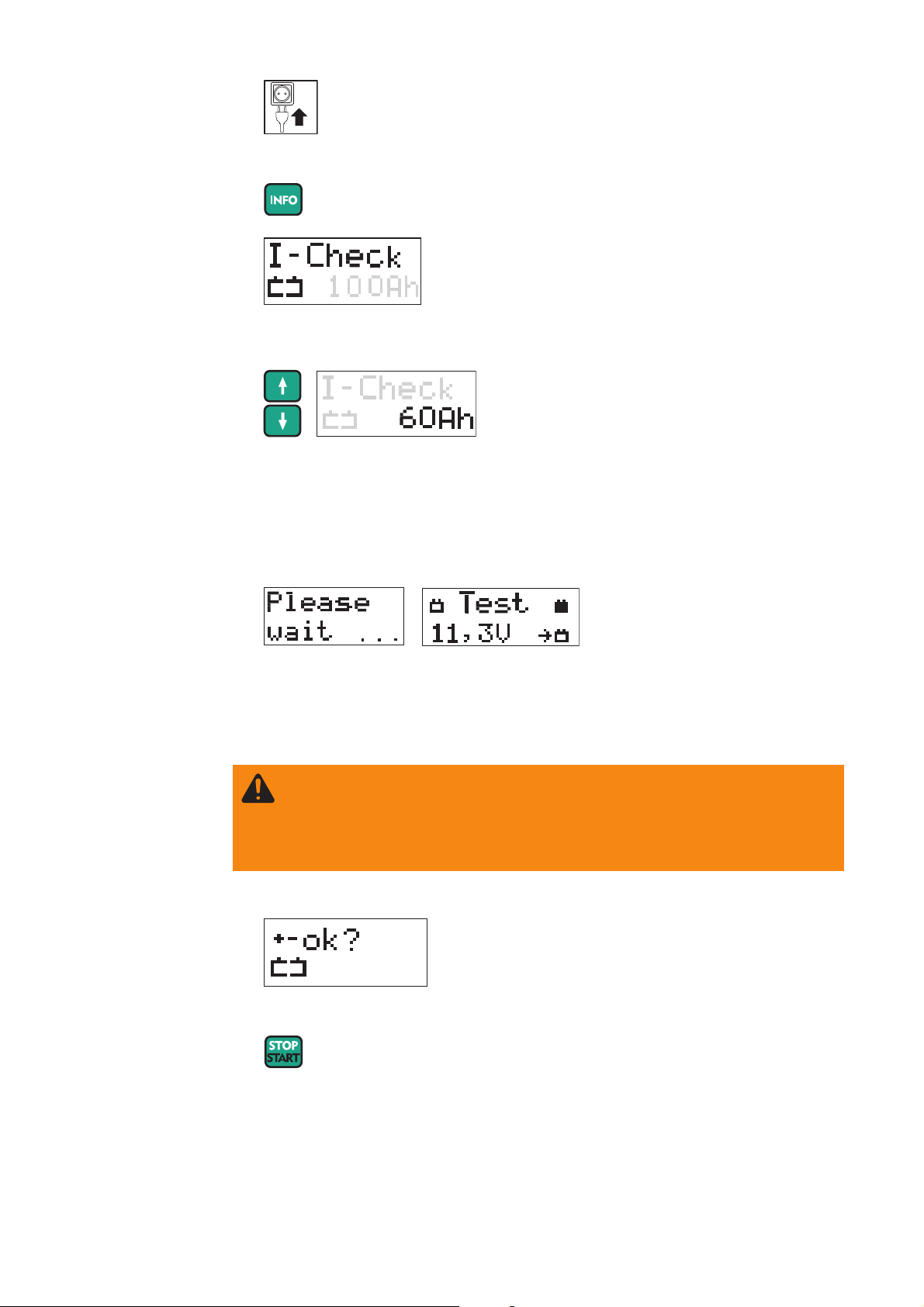
Starting charging
EN
1.
2. Select battery type and corresponding operating mode
Standard wet charging
Refresh wet charging
User wet charging
3. Set the capacity of the battery to be loaded.
Depending on the SYSTEM SETTINGS, the battery capacity can be set in:
- Ah (Ampere hours)
- RC (Reserve Capacity)
- CCA (Cold Cranking Amp)
After the battery capacity has been set, the charging current calculated from this is
shown on the display.
4. Connect (+) charging terminal to positive pole on battery
5. Connect (-) charging terminal to negative pole on the battery, or to vehicle body (e.g.
engine block) in the case of vehicle electrical systems.
Charger detects that the battery is connected, carries out a self test and starts charging.
Self test
E.g.: charging
Important! If the battery voltage is < 1.0 V, the battery will not be automatically detected.
Charging must be started manually.
9
Page 22

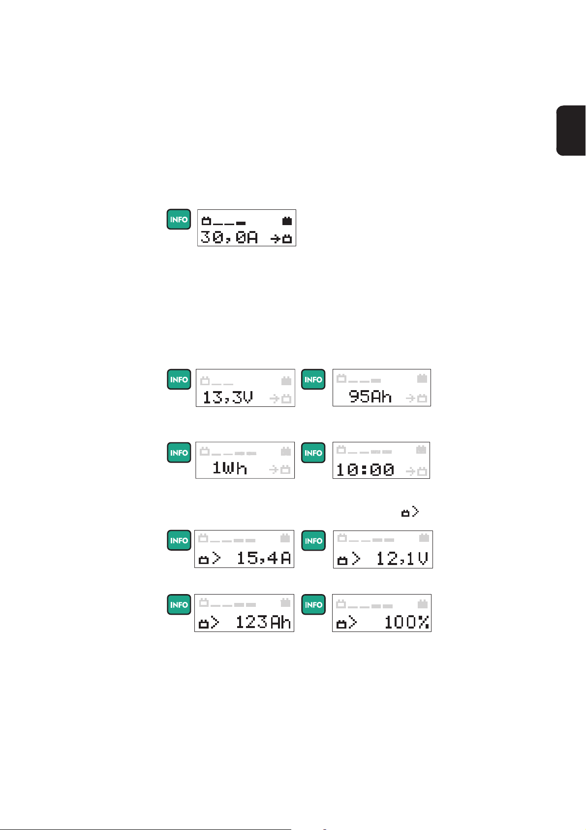
Retrieving parameters during
charging
Press the info button to display the parameters in the following sequence:
Retrieving parameters when
charging has
stopped
E.g.: actual charging current
E.g.: amount of charge fed
in
E.g.: length of time charging
so far
E.g.: actual battery voltage
E.g.: energy fed in
The top half of the display shows current progress and the bottom half shows the relevant values.
Press the Info button to display the parameters in the following sequence:
E.g.: actual charging current
E.g.: amount of charge fed
in
E.g.: length of time charging
so far
E.g.: actual battery voltage
E.g.: energy fed in
The top half of the display shows current progress and the bottom half shows the relevant values.
10
Page 23

WARNING! Risk of serious damage as a result of incorrectly connected charging terminals. The reversal polarity protection facility is inoperative if charging
is started manually (battery voltage < 1.0 V). Connect charging terminals to
correct poles and ensure proper electrical connection to vehicle terminals.
Starting charging
manually (deepdischarge battery)
1. Once the charging terminals are connected, press start/stop button for approx. 5
secs
EN
2. Ensure charging terminals are connected to correct poles
3. Starting charging
If there is no confirmation of correct pole connection within 2.5 secs, the device reverts
to menu mode.
1. During charging, the number of bars indicates how charging is progressing.Charging
2. Final charging stage - once the battery is approx. 80 - 85 % charged
- Display shows 6 consecutive bars
- Battery is now ready for use
Important! the charger automatically switches over to conservation charging after
approx. 3 - 7 hours, depending on the type of battery.
To charge the battery completely, the battery should remain connected to the charger for
this length of time.
NOTE! Only in Refresh charging mode:
When refresh charging has finished, the machine switches off. Conservation
charging does not take place.
11
Page 24

Charging
CAUTION! Risk of sparks when disconnecting the charging terminals. Before
disconnecting the charging terminals, stop charging by pressing the Start/Stop
button.
(continued)
3. When the battery is fully charged, the charger begins conservation charging.
- all bars are permanently displayed
- The battery is 100 % charged
- Battery is always ready to use
- Battery can remain connected to charger for as long
as required
- Conservation charging counteracts battery selfdischarge
NOTE! during charging (standard charging, user charging), increased demand
for current can lead to a drop in battery voltage (e.g. switching on additional
consumer loads). To compensate, the charger can briefly increase the current
to the maximum charging current (see Technical Data, user-defined settings in
USER menu).
Interrupting
charging
1. Press Start/Stop button to interrupt charging
2. Press the Info button to display the parameters in the following sequence:
- actual charging current
- actual battery voltage
- amount of charge (Ah) fed in so far
- energy (Wh) fed in so far
- length of time charging so far
3. Press Start/Stop button again to resume charging
Self test
E.g.: charging continues
Finishing charging/disconnecting the battery
1. Finish charging
2. Disconnect (-) charging terminal from battery
3. Disconnect (+) charging terminal from battery
4.
12
Page 25

Flash operation
WARNING! Risk of serious damage as a result of incorrectly connected char-
ging terminals. The reverse polarity protection facility is inoperative if the „flash
operation“ is started manually. Connect charging terminals to correct poles and
ensure proper electrical connection to vehicle terminals.
Starting the
„flash operation“
1.
EN
2. For external power supply, select „flash operation“ mode
3. Connect (+) charging terminal to positive pole on battery
4. Connect (-) charging terminal to negative pole on the battery, or to vehicle body (e.g.
engine block) in the case of vehicle electrical systems
Charger detects that the battery is connected, carries out a self test and starts the „flash
operation“.
Self test
Starting the
„flash operation“
manually
- the maximum voltage command value set in the
USER menu is shown in the top half of the display
E.g.: „Flash operation“
5. Press the Info button to display the parameters in the following sequence:
- actual charging current
- actual battery voltage
- amount of charge (Ah) fed in so far
- energy (Wh) fed in so far
- length of time charging so far
Important! Start the „flash operation“ manually if:
- there is no battery connected to the vehicle
- the battery voltage on the connected battery is < 1.0 V
1. Once the charging terminals are connected, press start/stop button for approx. 5
secs
- the current parameters are shown in the bottom
half of the display.
13
Page 26

CAUTION! Risk of sparks when disconnecting the charging terminals. Before
disconnecting the charging terminals, stop the „flash operation“ by pressing the
Start/Stop button.
Starting the
„flash operation“
manually
(continued)
2. Ensure charging terminals are connected to correct poles
3. Start the „flash operation“
If there is no confirmation of correct pole connection within 2.5 secs, the device reverts
to menu mode.
Boost mode
Stopping the
„flash operation“
If the battery voltage drops while power is being supplied externally because more power
is needed (e.g. because additional consumer loads are switched on), the device goes
into boost mode.
Important! To maintain the battery voltage at a constant level, the charger can increase
the current in boost mode to the maximum charging current (see Technical Data).
To prevent the device overheating, the max. output current can be automatically limited if
the ambient temperature rises to above 35°C/95°F (power derating).
1. Stop the „flash operation“
2. Press the Info button to display the parameters in the following sequence:
- actual charging current
- actual battery voltage
- amount of charge (Ah) fed in so far
- energy (Wh) fed in so far
- length of time charging so far
3. Disconnect (-) charging terminal from battery
4. Disconnect (+) charging terminal from battery
5.
14
Page 27

Charge acceptance test
General
Preparations
Charge acceptance test mode is used to determine a battery’s ability to accept a charge.
The charge acceptance test takes place as follows:
- charge acceptance testing is conducted automatically within a few minutes; if the
result is positive, the device will then switch automatically to standard charging
mode and charge the battery
- if the result is negative, „Test Fail“ appears on the charger’s screen and charging of
the battery is halted
A prerequisite for a satisfactory charge acceptance test is compliance with EU standard
EN-50342-1:2006 item 5.4 (battery approx. 50% discharged).
To ensure the battery is about 50% discharged, the following preparations can be carried
out immediately before the charge acceptance test:
1. Fully charge the battery
2. Calculate the discharge current
Battery capacity (Ah)
=
10
EN
3. Charge battery for approx. 5 hours with the calculated discharge current
15
Page 28
WARNING! Risk of serious damage if the charging terminals are connected
incorrectly. The reverse polarity protection facility is inoperative if the current
input test is started manually (battery voltage < 1.5 V). Connect charging
terminals to correct poles and ensure proper electrical connection to vehicle
terminals.
Start the charge
acceptance test
1.
2. Select charge acceptance test mode
Charge acceptance test
3. Set the capacity of the battery to be tested
4. Connect (+) charging terminal to positive pole on battery
5. Connect (-) charging terminal to negative pole on the battery, or to vehicle body (e.g.
engine block) in the case of vehicle electrical systems
Starting the
charge acceptance test manually
Charger detects that the battery is connected, carries out a self-test and starts the
charge acceptance test.
Self test Charge acceptance test
1. Once the charging terminals are connected, press start/stop button for approx. 5 secs
2. Ensure charging terminals are connected to correct poles
3. Start test
If there is no confirmation of correct pole connection within 2.5 secs, the device reverts
to menu mode.
16
Page 29
Retrieving parameters during the
charge acceptance test
1. Press the info button to display the parameters in the following sequence:
- actual charging current
- actual battery voltage
- amount of charge (Ah) fed in so far
- energy (Wh) fed in so far
- time that has elapsed since the start of the test (hh:mm)
EN
Charge acceptance test finished - battery OK
1. After the charge acceptance test has been carried out the device will switch automatically to standard charging mode and charge the battery
- the top half of the display features
progress bars to show the progress of
the current charging operation.
E.g.: actual charging
current
- the bottom half of the display shows
the current charging parameters /
calculated test parameters
2. Press the Info button to view stored test parameters and the actual charging parameters.
Charging parameters:
E.g.: actual battery voltage
E.g.: amount of charge fed
in
E.g.: energy fed in
E.g.: length of time charging
so far
Test parameters: can be identified by the test symbol
E.g.: charging current
E.g.: set battery capacity
E.g.: battery voltage
E.g.: Battery’s capacity to
accept charge, expressed
in %
17
Page 30

Charge acceptance test finished - battery
faulty
Important: A fully-charged battery can also return a negative test result. In this case the
battery must be discharged (see chapter entitled Charge acceptance test - Preparations)
1. The charge acceptance test shows that the battery is faulty. The battery receives no
further charge. The result is displayed on the screen:
- the top half of the display shows
the result of the charge acceptance
test (if the result is negative, „Test
E.g.: charging current
Fail“ is displayed)
- the bottom half of the display shows
the calculated parameters
2. Press the Info button to retrieve the following parameters:
E.g.: set battery capacityE.g.: battery voltage
E.g.: Battery’s capacity to
accept charge, expressed
in %
3 . If the terminals are disconnected from the battery in this mode, the charger reverts
to the Operating Mode menu.
18
Page 31

Setup menu
WARNING! Operating the equipment incorrectly can cause serious damage.
The functions described must only be carried out by trained and qualified
personnel. In addition to the safety rules in these operating instructions, the
safety rules of the battery and vehicle manufacturers must also be followed.
General remarks The setup menu gives you the ability to configure the device’s basic settings according
to your own requirements. You can also store frequently used charge settings.
EN
Accessing setup
menu, overview
1. To access menu: press info button for approx. 5 secs
2. Select menu item
User U/I
Setting characteristics and parameters
(end-of-charging voltage, charging current, conservation
voltage, max. charging period, etc.)
PREFERRED SETTINGS
Saves the frequently used operating modes you wish to keep
once the charger leads are removed or the charger is disconnected from the mains.
CHARGING CABLE
Settings defining the length and cross-section of the charging
cable.
SYSTEM SETTINGS
Setting the unit of measurement for battery capacity.
FACTORY SETTING
Resets device to factory setting
DELAY TIME
Sets the charging start delay time. Charging starts after a
predefined period.
DEVICE VERSION
For querying the current hardware and firmware version .
Device history
Checking operating hours counter.
EXIT SETUP
Exits the setup menu.
19
Page 32

Accessing setup
menu, overview
(continued)
Accessing
USER U/I
3. Open the desired menu
Important! If no selection is made within 30 seconds, the setup menu is exited automatically.
1. Open the USER U/I menu
2. Enter password 3831:
- Using the arrow keys, enter the correct digit in the underlined position
- Press the info button to go to the next position
- Repeat the process until all four digits have been entered correctly
- Press the Start/Stop button to confirm the password is correct
USER U/I menu,
standard charging settings
Set maximum charging current (Setting range: see Technical Data)
- Press Start/Stop button
- Display flashes. Adjust max. charging current in 0.5 A steps
- Press Start/Stop button to confirm setting
Set main charging voltage (setting range: 12.0 - 15.5 V)
- Press Start/Stop button
- Display flashes. Adjust main charging voltage in 0.1 V steps
- Press Start/Stop button to confirm setting
20
Page 33

USER U/I menu,
standard charging settings
(continued)
Set conservation charging voltage (setting range: Off / 12.0 - 15.5 V)
- Press Start/Stop button
- Display flashes. Adjust conservation charging voltage in 0.1 V steps
- Press Start/Stop button to confirm setting
EN
IMPORTANT! the conservation charging voltage is only available in Charge mode.
Conservation charging does not take place if conservation charging is set to OFF.
However, if the battery voltage drops below 12 V, charging starts.
Set safety cut-out (setting range: 2 h - 30 h)
- Press Start/Stop button
- Display flashes. Adjust time in 10 min intervals
- Press Start/Stop button to confirm setting
USER U/I menu,
user charging
settings
IMPORTANT! if charging does not end automatically after the set time has elapsed, the
charger will be switched off as a safety precaution.
Set maximum charging current (Setting range: see Technical Data)
- Press Start/Stop button
- Display flashes. Adjust max. charging current in 0.5 A steps
- Press Start/Stop button to confirm setting
Set main charging voltage (setting range: 12.0 - 15.5 V)
- Press Start/Stop button
- Display flashes. Adjust main charging voltage in 0.1 V steps
- Press Start/Stop button to confirm setting
21
Page 34

USER U/I menu,
user charging
settings
(continued)
Set main charging voltage (setting range: 12.0 - 15.5 V)
- Press Start/Stop button
- Display flashes. Adjust main charging voltage in 0.1 V steps
- Press Start/Stop button to confirm setting
IMPORTANT! the conservation charging voltage is only available in Charge mode.
Conservation charging does not take place if conservation charging is set to OFF.
However, if the battery voltage drops below 12 V, charging starts.
Set safety cut-out (setting range: 2 h - 30 h)
- Press Start/Stop button
- Display flashes. Adjust time in 10 min intervals
- Press Start/Stop button to confirm setting
USER U/I menu,
„flash operation“
settings
IMPORTANT! if charging does not end automatically after the set time has elapsed, the
charger will be switched off as a safety precaution.
Set the maximum current for „flash operation“ (Setting range: see Technical Data)
- Press Start/Stop button
- Adjust „flash operation“ current in 0.5 A steps
- Press Start/Stop button to confirm setting
Set the „flash operation“ voltage (setting range: 12.0 - 15.5 V)
- Press Start/Stop button
- Adjust „flash operation“ voltage in 0.1 V steps
- Press Start/Stop button to confirm setting
22
Page 35

USER U/I menu,
refresh charging
settings
Set refresh charging voltage (setting range: 12.0 - 17.0 V)
- Press Start/Stop button
- Adjust refresh charging voltage in 0.1 V steps
- Press Start/Stop button to confirm setting
EN
Set refresh charging period (setting range: 2 - 30h)
- Press Start/Stop button
- Adjust refresh charging period in 10 minute steps
- Press Start/Stop button to confirm setting
User U/I menu
Exit
PRESET menu
(preferred settings)
3. Press Start/Stop button to exit
Important! to avoid damage to the vehicle electronics, the following modes cannot be
saved:
- Refresh charging
1. Open the Preset menu
2. Select an option from the preset menu
Preferred Setting Used Mode (factory setting):
After disconnecting the charging terminals or mains supply, the last mode selected is saved.
23
Page 36

PRESET menu
(preferred settings)
(continued)
Preferred Setting: modes
Save charge acceptance test, standard charging, user charging, „flash operation“. After disconnecting the charging terminals or mains supply, the modes are
saved.
CHARGING
CABLE menu
Charge acceptance test
User charging
Standard charging
Flash operation
3. Save the desired mode and exit the menu.
Important! Regardless of the „preferred setting“ saved, another mode can be selected
at any time. After disconnecting the charging terminals or mains supply, the device
automatically reverts to the saved „preferred setting“.
1. Open the CHARGING CABLE menu
2. If necessary, change measure (metric/imperial) by pressing the info button:
3. Set the length of the charger cable. Setting range: 1 to 25 m (3 ft. 3 in. to 82 ft.)
- Press Start/Stop button
- Display flashes. Set the length of the charger cable
- Press Start/Stop button to confirm setting
24
Page 37

CHARGING
CABLE menu
(continued)
SYSTEM SETTINGS menu
4. Set the cross-section of the charger cable.
Setting range: 4 - 6 - 10 - 16 - 25 - 35 - 50 mm2 (AWG 10 to AWG 1)
- Press Start/Stop button
- Display flashes. Set the cross-section of the charger cable
- Press Start/Stop button to confirm setting
EN
5. Press Start/Stop button to exit
1. Open the SYSTEM SETTINGS menu
2. Select the desired unit of measurement for battery capacity
3. Save the selected settings and exit the SYSTEM SETTINGS menu
25
Page 38

FACTORY SETTING
DELAY TIME
menu
Reset device to factory setting:
1.
2. „Device resetted“ appears for 1 second
3. Device has been reset to factory setting. The submenu is exited automatically.
1. Open the DELAY TIME menu
2. Set delay time. Setting range: 0 - 4 h
3. Save the selected time and exit the DELAY TIME menu
Important! Delay time must be set again after each cycle. If the power fails, the countdown stops. Once the power is restored, the countdown continues where it left off.
DEVICE VERSION menu
1. Open the DEVICE VERSION menu
26
Page 39

DEVICE VERSION menu
(continued)
2. Toggle between the Firmware version, Boot program, Hardware and Exit displays by
pressing the arrow keys.
EN
Firmware
Displays the firmware version
Boot program
Displays the boot program version
Hardware
Displays the hardware version installed on the device
Exit
Press Start/Stop button to exit the DEVICE VERSION menu
DEVICE HISTORY
menu
1. Open the DEVICE HISTORY menu
2. Toggle between the Operating Hours, Charging Hours, Cumulated Ampere Hours
and Exit displays by pressing the arrow keys.
Operating Hours
Shows the operating hours (device connected to the mains or
switched on)
Charging Hours
Displays the operating time (time during which the device has
been producing power)
Cumulated Ampere Hours
Displays the amount of charge produced
Exit
Press Start/Stop button to exit the menu
27
Page 40

Troubleshooting
Troubleshooting
Charging terminals connected to wrong poles
Cause: Charging terminals connected to wrong poles
Remedy: Swap charging terminals round
Charging terminals short-circuited
Cause: Short-circuit on the charging terminals
Remedy: Rectify short-circuit on the charging terminals
Cause: Battery not detected
Remedy: Check that charging terminals are properly connected, press Start/Stop
button for 5 seconds
Over-temperature
Cause: Over-temperature - charger too hot
Remedy: Allow charger to cool down
Cause: Air inlets and outlets covered
Remedy: Ensure air inlets and outlets are not obstructed
Safety cut-out
Cause: Battery faulty
Remedy: Check battery
Cause: Charger incorrectly set
Remedy: Check settings: Ah, voltage
Cause: Incorrect battery type (e.g. NiCd), incorrect number of cells (voltage)
Remedy: Check battery type
Fan blocked/faulty
Cause: Fan blocked
Remedy: Check air inlet, remove foreign bodies if necessary
Cause: Fan faulty
Remedy: Contact specialist dealer
Fuse faulty
Cause: Secondary fuse faulty
Remedy: Contact specialist dealer
28
Page 41

Troubleshooting
(continued)
Charger faulty
Cause: Charger faulty
Remedy: Contact specialist dealer
EN
Nothing on display
Cause: Mains supply interrupted
Remedy: Connect mains supply
Cause: Mains plug or mains cable faulty
Remedy: Replace mains plug or mains cable
Cause: Charger faulty
Remedy: Contact specialist dealer
Charger does not start charging
Cause: Charging terminals or charger lead faulty
Remedy: Replace charging terminals or charger lead
(M8 nut torque = 15 Nm)
Symbols used
Warning notices
affixed to the
charger
Follow operating instructions
Connect battery poles correctly:
(+) red (-) black
Detonating gas is generated in the battery during charging.
Risk of explosion!
The charger heats up depending on operating conditions.
Before disconnecting the charger lead from the battery,
interrupt charging
Chargers may only be opened by a qualified electrician
Avoid flames and sparks during charging.
Ensure adequate ventilation during charging.
Battery acid is corrosive.
For indoor use only.
Do not expose to rain.
29
Page 42

Technical data
Acctiva
Professional
Flash UCN CN
Acctiva
Professional
Flash UCN US
Acctiva
Professional 30A
UCN
Mains voltage (+/- 15%)
Acctiva Professional Flash UCN CN 115 V AC, 50/60 Hz
Acctiva Professional Flash UCN US 115 V AC, 50/60 HZ
Acctiva Professional 30A UCN 115 V AC, 50/60 HZ
Nominal output max.
Acctiva Professional Flash UCN CN 1080 W
Acctiva Professional Flash UCN US 1080 W
Acctiva Professional 30A UCN 710 W
Charging voltage 12.0 - 15.5 V
Charging current I2 (adjustable)
Acctiva Professional Flash UCN CN 2 - 50 A
Acctiva Professional Flash UCN US 2 - 50 A
Acctiva Professional 30A UCN 2 - 30 A
Boost mode charging current t
Acctiva Professional Flash UCN CN max. 70 A
Acctiva Professional Flash UCN US max. 70 A
Acctiva Professional 30A UCN max. 30 A
Nominal charging capacity 10 - 300 Ah
Number of cells 6
Charging characteristic IUoU / IUa / IU
Operating temperature * 0°C to +60°C
Storage temperature -20°C to +80°C
Interface USB
Climate class (EN50178) B
EMC Class
Acctiva Professional Flash UCN CN FCC Part 15 (EMC class A)
Acctiva Professional Flash UCN US FCC Part 15 (EMC class A)
Acctiva Professional 30A UCN FCC Part 15 (EMC class A)
Protection IP 21
Marks of conformity see charger rating plate
Weight inclusive of mains and charger leads 6.5 kg
Dimensions w x h x d 315 x 200 x 110 mm
2 max
(tI
= 30 s, tI2 = 60 s)
2 max
32°F to 140°F
4°F to 176°F
14.33 lb.
12.40 x 7.87 x 4.33 in.
* To prevent the device overheating, the max. output current can be automatically
limited if the ambient temperature rises to above 35°C/95°F (power derating).
30
Page 43

Consignes de sécurité
AVERTISSEMENT !
ATTENTION !
REMARQUE :
Important !
Généralités
„AVERTISSEMENT !“ Signale une situation potentiellement dangereuse.
Si elle n’est pas évitée, elle peut entraîner la mort ou des blessures graves.
„ATTENTION !“ Signale une situation susceptible de provoquer des
dommages. Si elle n’est pas évitée, elle peut entraîner des blessures
légères ou minimes, ainsi que des dommages matériels.
„REMARQUE :“ désigne un risque de mauvais résultat de travail et de
possibles dommages sur l’équipement.
„Important !“ désigne une astuce d’utilisation et d’autres informations
particulièrement utiles. Cette mention ne signale pas une situation dangereuse ou susceptible de provoquer des dommages.
Soyez extrêmement attentif lorsque vous voyez l’un des symboles illustrés
dans le chapitre „Consignes de sécurité“.
Cet appareil est fabriqué selon l’état actuel de la technique et conformément
aux règles techniques de sécurité en vigueur. Cependant, en cas d’erreur
de manipulation ou de mauvaise utilisation, il existe un risque
- de blessure et de mort pour l’utilisateur ou des tiers,
- de dommages pour l’appareil et les autres biens de l’utilisateur,
- d’inefficacité du travail avec l’appareil.
FR
Toutes les personnes concernées par la mise en service, l’utilisation,
l’entretien et la maintenance de l’appareil doivent
- posséder les qualifications correspondantes,
- connaître le maniement des chargeurs et des batteries, et
- lire attentivement et suivre avec précision les instructions du présent
mode d’emploi.
Le mode d’emploi doit être conservé en permanence sur le lieu d’utilisation
de l’appareil. En complément du présent mode d’emploi, les règles générales et locales en vigueur concernant la prévention des accidents et la
protection de l’environnement doivent être respectées.
Concernant les avertissements de sécurité et de danger présents sur
l’appareil :
- veiller à leur lisibilité permanente
- ne pas les détériorer
- ne pas les retirer
- ne pas les recouvrir, ni coller d’autres autocollants par-dessus, ni les
peindre.
Vous trouverez les emplacements des avertissements de sécurité et de
danger présents sur l’appareil au chapitre „Généralités“ du mode d’emploi
de votre appareil.
Éliminer les pannes qui peuvent menacer la sécurité avant de mettre
l’appareil sous tension.
Votre sécurité est en jeu !
I
ud_fr_ls_sv_01056 012014
Page 44

Utilisation conforme
Cet appareil est exclusivement destiné à une utilisation dans le cadre d’un
emploi conforme aux règles en vigueur. Toute autre utilisation est considérée comme non conforme. Le fabricant décline toute responsabilité en ce
qui concerne les dommages qui en résulteraient, ainsi que les résultats de
travail défectueux ou erronés.
Font partie de l’emploi conforme
- la lecture attentive et le respect du mode d’emploi et de tous les avertissements de sécurité et de danger
- le respect des travaux d’inspection et de maintenance
- le respect de toutes les instructions données par le fabricant de la
batterie et du véhicule
Le fonctionnement irréprochable de l'appareil est fonction d'un maniement
approprié. Lors de toute manipulation, l'appareil ne doit en aucun cas être
tiré au niveau du câble.
Conditions
d’utilisation
Risques liés au
courant
d’alimentation et
de charge
Tout fonctionnement ou stockage de l’appareil en dehors du domaine
d’utilisation indiqué est considéré comme non conforme. Le fabricant ne
saurait être tenu pour responsable des dommages consécutifs.
Vous trouverez des informations plus précises concernant les conditions
d’utilisation admises dans les caractéristiques techniques de votre mode
d’emploi.
Le travail avec les chargeurs expose à de nombreux risques, par ex. :
- risque électrique lié au courant d’alimentation et de charge
- champs magnétiques nocifs pouvant être à l’origine d’un risque vital
pour les porteurs de stimulateurs cardiaques
Un choc électrique peut être mortel. Tout choc électrique peut en principe
entraîner la mort. Pour éviter les chocs électriques en cours de service :
- éviter tout contact avec des pièces conductrices à l’intérieur et à
l’extérieur de l’appareil
- ne jamais toucher les pôles de la batterie
- ne pas provoquer de court-circuit dans les câbles de chargement ou les
pinces de chargement
Tous les câbles et les connexions doivent être solides, intacts, isolés et de
capacité suffisante. Faire réparer sans délai les connexions lâches, encrassées, endommagées ou les câbles sous-dimensionnés par une entreprise
spécialisée agréée.
Raccordement au
secteur
ud_fr_ls_sv_01056 012014
En raison de leur absorption de courant élevée, les appareils de forte puissance influent sur la qualité énergétique du réseau d’alimentation.
Certains types d’appareils peuvent être touchés sous la forme :
- de restrictions de raccordement
- d’exigences relatives avec l’impédance maximale autorisée du secteur
- d’exigences relatives à la puissance de court-circuit nécessaire
*)
à l’interface avec le réseau public
*)
voir caractéristiques techniques
Dans ce cas, l’exploitant ou l’utilisateur de l’appareil doit s’assurer que
l’appareil peut être raccordé au réseau, au besoin en prenant contact avec le
distributeur d’électricité.
II
*)
Page 45

Risques liés à
l’acide, aux gaz
et aux vapeurs
Les batteries contiennent des acides nocifs pour les yeux et la peau. En
outre, lors du chargement des batteries se dégagent des gaz et des vapeurs
pouvant être à l’origine de problèmes de santé et hautement explosifs dans
certaines circonstances.
- Utiliser le chargeur uniquement dans des pièces bien aérées afin
d’éviter toute accumulation de gaz explosifs. Les locaux pour batteries
sont considérés comme non-exposés aux risques d’explosion
lorsqu’une concentration d’hydrogène inférieure à 4 % est assurée
grâce à une ventilation naturelle ou technique.
- Lors du chargement, maintenir un espace minimal de 0,5 m entre la
batterie et le chargeur. Éloigner des batteries les sources d’inflammation
potentielles, ainsi que le feu et les lampes découvertes
- Ne débrancher en aucun cas la connexion à la batterie (par ex. pinces
de chargement) pendant le processus de chargement
- Ne pas inhaler les gaz et vapeurs dégagés
- Veiller à assurer une ventilation suffisante
- Ne pas poser d’outils ou de pièces de métal conductrices d’électricité
sur la batterie, afin d’éviter les courts-circuits
- Éviter impérativement le contact de l’acide de la batterie avec les yeux,
la peau ou les vêtements. Porter des lunettes et des vêtements de
protection adaptés. Rincer immédiatement et abondamment les projections d’acide à l’eau claire, si nécessaire consulter un médecin.
FR
Instructions
générales relatives à la manipulation des batteries
Protection de
l’utilisateur et
des personnes
- Protéger les batteries contre l’encrassement et les dommages mécaniques.
- Stocker les batteries chargées dans des locaux réfrigérés.
L’autodéchargement est le plus faible à environ +2 °C (35.6 °F).
- Au moyen d’une inspection visuelle hebdomadaire, vérifier que la
batterie est remplie d’acide (électrolyte) jusqu’au repère de niveau
maximum.
- Ne pas démarrer le fonctionnement de l’appareil ou l’arrêter immédiatement et faire vérifier la batterie par un spécialiste agréé dans les cas
suivants :
- niveau d’acide non homogène ou consommation d’eau élevée dans
les différentes cellules provoquée par un possible défaut
- surchauffe non autorisée de la batterie à plus de 55 °C (131 °F)
Tenir à distance de l’appareil et de la zone de travail les autres personnes,
en particulier les enfants, pendant le fonctionnement. Si des personnes se
trouvent tout de même à proximité :
- les informer de tous les risques qu’elles encourent (acides et gaz nocifs,
danger dû au courant d’alimentation et de charge, ...)
- mettre à leur disposition les moyens de protection appropriés.
Avant de quitter la zone de travail, s’assurer qu’aucun dommage corporel ou
matériel ne peut survenir, même en votre absence.
Mesures de
sécurité en
service normal
- Utiliser les appareils munis d’un conducteur de terre uniquement sur un
réseau avec conducteur de terre et une prise avec contact de terre. Si
l’appareil est utilisé sur un réseau sans conducteur de terre ou avec une
prise sans contact de terre, il s’agit d’une négligence grossière. Le fabricant ne saurait être tenu pour responsable des dommages consécutifs.
- Utiliser l’appareil uniquement en conformité avec la classe de protection
indiquée sur la plaque signalétique.
III
ud_fr_ls_sv_01056 012014
Page 46

Mesures de
sécurité en
service normal
(Suite)
- Ne jamais mettre l’appareil en service lorsqu’il présente des dommages.
- Veiller à ce que l’air de refroidissement puisse entrer et sortir sans
entrave par les fentes d’aération de l’appareil.
- Faire contrôler régulièrement l’alimentation du réseau et de l’appareil par
un électricien spécialisé afin de vérifier le bon fonctionnement du conducteur de terre.
- Faire réparer les dispositifs de sécurité défectueux et les pièces présentant des dommages avant la mise en service de l’appareil par une
entreprise spécialisée agréée.
- Ne jamais mettre hors circuit ou hors service les dispositifs de sécurité.
- Après l’installation, une prise secteur facilement accessible est nécessaire.
Classification
CEM des appareils
Mesures relatives
à la CEM
Sûreté des
données
Appareils de la classe d’émissions A :
- ne sont prévus que pour une utilisation dans les zones industrielles
- peuvent entraîner des perturbations de rayonnement liées à leur
puissance
Appareils de la classe d’émissions B :
- répondent aux exigences d’émissions pour les zones habitées et
les zones industrielles ainsi que pour les zones habitées dans
lesquelles l’alimentation énergétique s’effectue à partir du réseau
public basse tension
Classification CEM des appareils conformément à la plaque signalétique ou aux caractéristiques techniques
Dans certains cas, des influences peuvent se manifester dans la zone
d’application prévue malgré le respect des valeurs limites d’émissions
normalisées (p. ex. en présence d’appareils sensibles sur le site
d’installation ou lorsque ce dernier est situé à proximité de récepteurs radio
ou TV).
L’exploitant est alors tenu de prendre les mesures nécessaires pour éliminer
les dysfonctionnements.
L’utilisateur est responsable de la sûreté des données liées à des modifications par rapport aux réglages d’usine. Le fabricant décline toute responsabilité en cas de perte de réglages personnels.
Entretien et
maintenance
ud_fr_ls_sv_01056 012014
Lorsqu’il fonctionne dans des conditions normales, cet appareil exige un minimum de maintenance et d’entretien. Il est toutefois indispensable de respecter
certaines consignes, afin de le garder longtemps en bon état de marche.
- Avant chaque mise en service vérifier la présence éventuelle de dommages sur la fiche d’alimentation et le câble d’alimentation, ainsi que sur
les câbles de chargement et les pinces de chargement.
- En cas d’encrassement, nettoyer la surface du boîtier de l’appareil à
l’aide d’un chiffon doux et utiliser uniquement des produits de nettoyage
sans solvants.
Les travaux de réparation et de maintenance doivent être réalisés exclusivement par une entreprise spécialisée agréée. Utiliser uniquement les pièces
de rechange et d’usure d’origine (valable également pour les pièces standardisées). Les pièces provenant d’autres fournisseurs n’offrent pas de
garantie de construction et de fabrication conformes aux exigences de
qualité et de sécurité.
Ne réaliser aucune modification, installation ou transformation sur l’appareil
sans autorisation du fabricant.
Élimination conformément aux dispositions nationales et régionales en vigueur.
IV
Page 47

Garantie et
responsabilité
La durée de la garantie pour l’appareil s’élève à 2 ans à compter de la date
de facturation. Le fabricant décline cependant toute responsabilité lorsque
les dommages ont pour origine une ou plusieurs des causes suivantes :
- Emploi non conforme de l’appareil
- Montage et utilisation non conformes
- Fonctionnement de l’appareil avec des dispositifs de sécurité défectueux
- Non respect des instructions du mode d’emploi
- Modifications non autorisées réalisées sur l’appareil
- Sinistres survenus sous l’effet de corps étrangers et d’actes de violence
Contrôle technique de sécurité
Élimination
L’utilisateur est tenu de faire effectuer au moins tous les 12 mois un contrôle
technique de sécurité de l’appareil.
Au cours de ce même intervalle de 12 mois, le fabricant recommande un
calibrage des sources de courant.
Un contrôle technique de sécurité réalisé par un électricien spécialisé agréé
est prescrit :
- après toute modification
- après montage ou conversion
- après toute opération de réparation, entretien et maintenance
- au moins tous les douze mois.
Pour le contrôle technique de sécurité, respecter les normes et les directives nationales et internationales en vigueur.
Vous obtiendrez des informations plus précises concernant le contrôle
technique de sécurité et le calibrage auprès de votre service après-vente.
Ce service tient à votre disposition sur demande les documents requis.
Ne pas jeter cet appareil avec les déchets ménagers ordinaires !
Conformément à la directive européenne 2002/96/CE relative aux déchets
d’équipements électriques et électroniques (DEEE), et à sa transposition dans
la législation nationale, les appareils électriques doivent être collectés séparément et être soumis à un recyclage respectueux de l’environnement. Assurezvous de bien remettre votre appareil usagé à votre revendeur ou informezvous sur les systèmes de collecte ou d’élimination locaux approuvés.
Un non-respect de cette directive UE peut avoir des effets néfastes pour
l’environnement et la santé !
FR
Marquage de
sécurité
Les appareils portant la marque CE répondent aux exigences essentielles
de la directive basse tension et compatibilité électromagnétique.
Les appareils portant la marque TÜV répondent aux exigences des normes
applicables au Canada et aux États-Unis.
Les appareils portant la marque TÜV répondent aux exigences des normes
applicables au Japon.
V
ud_fr_ls_sv_01056 012014
Page 48

Marquage de
sécurité
(Suite)
Les appareils portant la marque TÜV et les marquages indiqués sur la
plaque signalétique répondent aux exigences des normes applicables en
Australie.
Droits de reproduction
Les droits de reproduction du présent mode d’emploi sont réservés au
fabricant.
Les textes et les illustrations correspondent à l’état de la technique au
moment de l’impression. Sous réserve de modifications. Le contenu du
mode d’emploi ne peut justifier aucune réclamation de la part de l’acheteur.
Nous vous remercions de nous faire part de vos propositions d’amélioration
et de nous signaler les éventuelles erreurs contenues dans le mode
d’emploi.
ud_fr_ls_sv_01056 012014
VI
Page 49

IMPORTANT : INSTRUCTIONS DE SÉCURITÉ
CONSERVEZ CES INSTRUCTIONS (Valables pour USA, Kanada, Australia)
1. CONSERVEZ CES INSTRUCTIONS - Ce manuel contient des instructions de sécurité et d’utilisation importantes
pour les différents modèles de chargeurs de batterie (pour le modèle voir la première page de ce document).
2. Maintenir le chargeur à l’abri de la pluie et de la neige.
3. L’utilisation d’un accessoire non recommandé ni vendu par le fabricant du chargeur de batterie risque d’être à
l’origine d’un incendie, d’un choc électrique ou de blessures corporelles.
Taille minimale AWG de la rallonge
25 ft (7,6 m) 50 ft (15,2 m) 100 ft (30,5 m) 150 ft (45,6 m)
AWG 16 AWG 12 AWG 10 AWG 8
4. Pour limiter les risques de détérioration de la prise et du cordon électriques, tirer sur la prise et non sur le cordon
pour débrancher le chargeur.
5. Ne pas utiliser de rallonge, sauf si cela est absolument nécessaire. L’utilisation d’une rallonge inadaptée risque
d’être à l’origine d’un incendie ou d’un choc électrique. Si vous utilisez une rallonge, assurez-vous :
a) que le nombre de broches de la prise de la rallonge est identique à celui de la prise du chargeur et qu’elles sont
de la même taille et de la même forme que celles de la prise du chargeur ;
b) que la rallonge est correctement câblée et en bon état électrique ; et
c) Cette section du câble est assez grande pour l’ampérage AC du chargeur, tel que spécifié ci-dessus.
6. Ne pas utiliser le chargeur avec un cordon ou une prise endommagé(e) - remplacer le cordon ou la prise immédiatement.
7. Ne pas utiliser le chargeur s’il a subi un choc violent, s’il est tombé ou s’il a été endommagé d’une façon quelconque
; apportez-le à un technicien qualifié.
8. Ne pas démonter le chageur ; apportez-le à un technicien qualifié si une opération de maintenance ou de réparation
est requise. Un montage incorrect après démontage peut provoquer un choc électrique ou un incendie.
9. Pour limiter les risques de choc électrique, débrancher le chargeur du secteur avant de commencer une opération
quelconque d’entretien ou de nettoyage. Éteindre les commandes ne suffit pas pour limiter ce risque.
10. ATTENTION - RISQUE DE PRÉSENCE DE GAZ EXPLOSIFS
a) LE TRAVAIL À PROXIMITÉ D’UNE BATTERIE PLOMB / ACIDE EST DANGEREUX. LES BATTERIES DÉGA-
GENT DES GAZ EXPLOSIFS AU COURS DE LEUR FONCTIONNEMENT NORMAL. POUR CETTE RAISON, IL
EST EXTRÊMEMENT IMPORTANT DE LIRE LE PRÉSENT MANUEL ET DE SUIVRE LES INSTRUCTIONS À LA
LETTRE AVANT CHAQUE UTILISATION DU CHARGEUR.
b) Afin de limiter le risque d’explosion de la batterie, suivre les présentes instructions et celles fournies par le
fabricant de la batterie et le fabricant de tout équipement destiné à être utilisé à proximité de la batterie. Vérifier
la signalisation de sécurité sur ces produits et sur le moteur.
11. PRÉCAUTIONS À PRENDRE POUR LES PERSONNES
a) Une personne doit être présente à portée de voix ou suffisamment près pour venir en aide à celui qui travaille à
proximité d’une batterie plomb / acide.
b) Prévoir une quantité importante d’eau fraîche et de savon à proximité en cas de contact de l’acide de la batterie
avec la peau, les vêtements ou les yeux.
c) Porter une protection intégrale des yeux et des vêtements de protection. Éviter le contact des mains avec les
yeux au cours du travail à proximité d’une batterie.
d) Si l’acide de la batterie entre en contact avec la peau ou les vêtements, laver immédiatement avec du savon et
de l’eau. En cas de projection d’acide dans les yeux, rincer immédiatement à l’eau courante froide pendant au
moins 10 minutes et consulter un médecin dans les plus brefs délais.
e) IL EST STRICTEMENT INTERDIT de fumer ou de provoquer la formation d’une étincelle ou d’une flamme à
proximité de la batterie ou du moteur.
f) Faire preuve d’une extrême prudence afin de limiter le risque de chute d’un outil en métal sur la batterie. Il risque
de générer une étincelle ou de court-circuiter la batterie ou un autre composant électrique, ce qui peut causer
une explosion.
g) Retirer les effets personnels en métal tels que les bagues, bracelets, colliers et montres pour travailler avec une
batterie plomb / acide. Une batterie plomb / acide peut produire un courant de court-circuit assez puissant pour
souder une bague ou autre objet métallique et provoquer de graves brûlures.
h) Utiliser le chargeur pour charger une batterie PLOMB / ACIDE exclusivement. Il n’est pas conçu pour alimenter
un système électrique basse tension autre que dans le cadre d’une application démarreur - moteur. Ne pas
utiliser le chargeur de batterie pour charger des batteries sèches, qui sont couramment employées dans les
appareils électroménagers. Ces batteries risquent d’éclater et de causer des blessures corporelles et des
dommages matériels.
i) NE JAMAIS charger une batterie gelée.
I
ud_fr_ls_sv_01087 032006
Page 50

12. AVANT DE CHARGER
a) S’il est nécessaire de retirer la batterie du véhicule pour la charger, toujours enlever d’abord la borne de mise à
la masse de la batterie. S’assurer que tous les accessoires dans le véhicule sont hors tension, de manière à ne
pas provoquer un arc.
b) S’assurer que l’espace autour de la batterie est bien ventilé lorsque la batterie est en charge. Les gaz peuvent
être évacués énergiquement à l’aide d’un morceau de carton ou d’un autre matériau non métallique en guise de
ventilateur.
c) Nettoyer les bornes de la batterie. Éviter tout contact de la corrosion avec les yeux.
d) Ajouter de l’eau distillée dans chaque cellule jusqu’à ce que l’acide de la batterie atteigne le niveau spécifié par
le fabricant de la batterie. Ceci permet de purger l’excédent de gaz des cellules. Ne pas faire déborder. Pour les
batteries sans couvercles, suivre avec attention les instructions de rechargement du fabricant.
e) Lire attentivement toutes les précautions particulières mentionnées par le fabricant de la batterie, par exemple en
ce qui concerne le retrait ou non des couvercles des éléments de batterie pendant le chargement et les taux de
charge recommandés.
f) Déterminer la tension de la batterie en se référant au manuel du propriétaire du véhicule et s’assurer qu’elle
correspond à la tension de sortie du chargeur de batterie.
13. EMPLACEMENT DU CHARGEUR
a) Placer le chargeur à distance de la batterie, aussi loin que le permettent les câbles.
b) Ne jamais placer le chargeur directement au-dessus de la batterie en charge ; les gaz dégagés par la batterie
peuvent corroder et endommager le chargeur.
c) Ne jamais laisser l’acide de la batterie goutter sur le chargeur pendant la mesure de la gravité ou le remplissage
de la batterie.
d) Ne pas utiliser le chargeur dans un espace clos ou mal ventilé.
e) Ne pas poser la batterie sur le chargeur.
14. PRÉCAUTIONS DE BRANCHEMENT DC
a) Brancher et débrancher les pinces de sortie DC uniquement après avoir placé les commutateurs du chargeur en
position d’arrêt et retiré le cordon AC de la prise électrique. Ne jamais laisser les pinces entrer en contact entre
elles.
b) Fixer les pinces sur la batterie et le châssis comme indiqué en 15(e), 15(f), 16(b) et 16(d).
c) Fixer les pinces aux pôles de la batterie et tourner ou basculer vers l’avant et l’arrière plusieurs fois afin d’établir
une connexion correcte. Ceci permet d’empêcher les pinces de glisser des bornes et limite le risque de formation
d’étincelle.
15. SUIVRE LES ÉTAPES CI-DESSOUS LORSQUE LA BATTERIE EST INSTALLÉE DANS LE VÉHICULE. LA FORMATION D’UNE ÉTINCELLE À PROXIMITÉ DE LA BATTERIE RISQUE DE PROVOQUER L’EXPLOSION DE LA
BATTERIE ; LIMITER LE RISQUE DE FORMATION D’ÉTINCELLE À PROXIMITÉ DE LA BATTERIE.
a) Positionner les cordons AC et DC de manière à limiter le risque de dommage causé par le capot, la porte ou un
élément mobile du moteur.
b) Se tenir à distance des pales de ventilateur, des courroies, des poulies et des autres pièces qui risquent de
provoquer des blessures corporelles.
c) Vérifier la polarité des pôles de la batterie. Le pôle POSITIF (POS, P, +) de la batterie présente normalement un
diamètre supérieur à celui du pôle NÉGATIF (NEG, N, -).
d) Déterminer quel pôle de la batterie est mis à la masse (connecté) au châssis. Si c’est le pôle négatif qui est mis
à la masse au châssis (c’est le cas dans la plupart des véhicules), voir le point (e). Si c’est le pôle positif qui est
mis à la masse au châssis, voir le point (f).
e) Pour les véhicules avec mise à la masse du pôle négatif, brancher la pince POSITIVE (ROUGE) du chargeur de
batterie au pôle POSITIF (POS, P, +) non mis à la masse de la batterie. Brancher la pince NÉGATIVE (NOIRE)
sur le châssis du véhicule ou le bloc moteur, à distance de la batterie. Ne pas brancher la pince sur le carburateur, les conduites d’essence ou les pièces de carrosserie en tôle. Brancher la pince sur une pièce métallique de
tôle courante du châssis ou du bloc moteur.
f) Pour les véhicules avec mise à la masse du pôle positif, brancher la pince NÉGATIVE (NOIRE) du chargeur de
batterie au pôle NÉGATIF (NEG, N, -) non mis à la masse de la batterie. Brancher la pince POSITIVE (ROUGE)
sur le châssis du véhicule ou le bloc moteur, à distance de la batterie. Ne pas brancher la pince sur le carburateur, les conduites d’essence ou les pièces de carrosserie en tôle. Brancher la pince sur une pièce métallique de
tôle courante du châssis ou du bloc moteur.
g) Pour débrancher le chargeur, placer les commutateurs en position d’arrêt, débrancher le cordon AC, retirer la
pince du châssis du véhicule puis retirer la pince de la borne de la batterie.
h) Lire les instructions d’utilisation pour en savoir plus sur la durée de chargement.
16. SUIVRE LES ÉTAPES CI-DESSOUS LORSQUE LA BATTERIE EST PLACÉE HORS DU VÉHICULE. LA FORMATION D’UNE ÉTINCELLE À PROXIMITÉ DE LA BATTERIE RISQUE DE PROVOQUER L’EXPLOSION DE LA BATTERIE ; LIMITER LE RISQUE DE FORMATION D’ÉTINCELLE À PROXIMITÉ DE LA BATTERIE.
a) Vérifier la polarité des pôles de la batterie. Le pôle POSITIF (POS, P, +) de la batterie présente normalement un
diamètre supérieur à celui du pôle NÉGATIF (NEG, N, -).
b) Relier un câble de batterie isolé calibre 6 (AWG) d’au moins 24 pouces de long au pôle NÉGATIF (NEG, N, -) de
la batterie.
c) Brancher la pince POSITIVE (ROUGE) du chargeur au pôle POSITIF (POS, P, +) de la batterie.
d) Se tenir le plus loin possible de la batterie et placer l’extrémité libre du câble à distance maximale de la batterie,
puis brancher la pince NÉGATIVE (NOIRE) du chargeur à l’extrémité libre du câble.
ud_fr_ls_sv_01087 032006
II
Page 51

e) Ne pas se placer en face de la batterie pour effectuer le branchement final.
f) Pour débrancher le chargeur, toujours suivre la procédure inverse de celle indiquée pour le branchement et
rompre la connexion aussi loin que possible de la batterie.
g) Une batterie marine (pour bateau) doit être déposée et chargée à terre. Pour la charger à bord, utiliser impérati-
vement un équipement spécialement conçu pour un usage en mer.
17. INSTRUCTIONS DE MISE À LA MASSE ET DE BRANCHEMENT DU CORDON D’ALIMENTATION AC – Le chargeur
doit être mis à la masse pour réduire les risques de choc électrique. Le chargeur est équipé d’un cordon électrique
doté d’un conducteur de mise à la masse des équipements et d’une prise de mise à la masse. La prise doit être
branchée dans une prise femelle correctement installée et mise à la masse conformément aux conventions et
réglementations locales en vigueur.
DANGER – Ne jamais effectuer de modifications sur le cordon AC ou la prise fournis – s’ils ne sont pas adaptés à la
prise femelle, faire installer une prise correcte par un électricien qualifié. Un branchement incorrect peut provoquer
un choc électrique.
Cet appareil présente une intensité supérieure à 15 ampères et est destiné à être utilisé sur un circuit d’une tension
nominale de 120 volts ; à la sortie de l’usine, il est équipé d’un cordon électrique et d’une prise spécifiques afin de
permettre le branchement sur un circuit électrique correct. Veiller à ce que le chargeur soit branché sur une prise
femelle de la même configuration que la prise mâle. Aucun adaptateur ne doit être utilisé avec ce chargeur.
18. Cet appareil n’est pas prévu à l’usage d’enfants en bas âge ou de personnes infirmes, à moins qu’ils ne soient
correctement supervisés par une personne responsable afin de garantir l’utilisation de l’appareil sans aucun risque.
Les jeunes enfants doivent être surveillés afin de s’assurer qu’ils ne jouent pas avec cet appareil.
Chargeur de batteries USA, 30 A + 50 A
REMARQUE : Cet équipement a fait l’objet de tests et a été démontré conforme aux limites pour un dispositif de
classe A, conformément à la partie 15 des règles FCC. Ces limites sont conçues afin de fournir une protection
raisonnable contre les interférences nuisibles lorsque l’équipement est utilisé dans un environnement commercial.
Cet équipement génère, utilise et peut diffuser de l’énergie sous forme de fréquences radioélectriques et, s’il n’est
pas installé et utilisé conformément au manuel d’instructions, il peut provoquer des interférences nuisibles aux
radiocommunications. L’utilisation de cet équipement dans une zone résidentielle est susceptible de provoquer des
interférences nuisibles ; dans ce cas, l’utilisateur sera tenu de corriger ces interférences à ses propres frais.
III
ud_fr_ls_sv_01087 032006
Page 52

ud_fr_ls_sv_01087 032006
IV
Page 53

Sommaire
Généralités .................................................................................................................................................... 3
Sécurité .................................................................................................................................................... 3
Utilisation conforme à la destination ........................................................................................................ 3
Symboles utilisés ..................................................................................................................................... 3
Éléments de commande et connexions ........................................................................................................ 4
Généralités ............................................................................................................................................... 4
Éléments de commande et connexions ................................................................................................... 4
Options de montage ...................................................................................................................................... 5
Option Montage du cadre de protection ................................................................................................... 5
Option Montage mural.............................................................................................................................. 5
Option Montage au sol ............................................................................................................................. 6
Modes de service .......................................................................................................................................... 7
Modes de service disponibles .................................................................................................................. 7
Méthode de chargement standard / chargement utilisateur ..................................................................... 7
Mode de service rechargement................................................................................................................ 8
Mode de service „flash opération“ ............................................................................................................ 8
Mode de service contrôle d’acceptation de courant ................................................................................. 8
Charger la batterie ........................................................................................................................................ 9
Commencer le processus de chargement ............................................................................................... 9
Appeler les paramètres pendant le processus de chargement .............................................................. 10
Appeler les paramètres lors de l’arrêt du chargement ........................................................................... 10
Démarrer le processus de chargement manuellement (batterie entièrement déchargée) ......................11
Processus de chargement ...................................................................................................................... 11
Interrompre le processus de chargement .............................................................................................. 12
Terminer le processus de chargement / Débrancher la batterie ............................................................ 12
Flash opération ........................................................................................................................................... 13
Démarrer „flash opération“ ..................................................................................................................... 13
Démarrer „flash opération“ manuellement ............................................................................................. 13
Mode Boost ............................................................................................................................................ 14
Terminer „flash opération“ ...................................................................................................................... 14
FR
Vérification d’acceptation de courant .......................................................................................................... 15
Généralités ............................................................................................................................................. 15
Préparations ........................................................................................................................................... 15
Démarrer manuellement la vérification d’acceptation de courant .......................................................... 16
Démarrer le contrôle d’acceptation de courant ...................................................................................... 16
Appeler les paramètres pendant le processus de vérification d’acceptation de courant ........................ 17
Vérification d’acceptation de courant terminé - Batterie OK................................................................... 17
Vérification d’acceptation de courant terminé - Batterie défectueuse .................................................... 18
Menu Setup ................................................................................................................................................. 19
Généralités ............................................................................................................................................. 19
Accès et aperçu du menu Setup ............................................................................................................ 19
Accès menu USER U/I ........................................................................................................................... 20
Menu USER U/I, réglages chargement standard ................................................................................... 20
Menu USER U/I, réglages chargement utilisateur..................................................................................21
Menu USER U/I, réglages „flash opération“ ........................................................................................... 22
Menu USER U/I, réglages rechargement ............................................................................................... 23
Menu User U/I Pour quitter .................................................................................................................... 23
Menu PRESET (préférences de réglage) .............................................................................................. 23
Menu CHARGING CABLE ..................................................................................................................... 24
Menu SYSTEM SETTINGS ................................................................................................................... 25
FACTORY SETTING .............................................................................................................................. 26
Menu DELAY TIME (démarrage différé) ................................................................................................ 26
Menu DEVICE VERSION ....................................................................................................................... 26
Menu DEVICE HISTORY ....................................................................................................................... 27
1
Page 54

Diagnostic et élimination des pannes .......................................................................................................... 28
Diagnostic et élimination des pannes ..................................................................................................... 28
Symboles utilisés ........................................................................................................................................ 29
Avertissements concernant l’appareil..................................................................................................... 29
Caractéristiques techniques ........................................................................................................................ 30
Acctiva Professional Flash UCN CN ...................................................................................................... 30
Acctiva Professional Flash UCN US ...................................................................................................... 30
Acctiva Professional 30A UCN ............................................................................................................... 30
2
Page 55

Généralités
ATTENTION ! Risque de dommages matériels et de mauvais résultats de
chargement en cas de mode de service mal réglé. Régler toujours le mode de
service en fonction du type de batterie à charger.
AVERTISSEMENT ! Risque de dommages corporels et matériels dus aux
pièces mécaniques à découvert et rotatives. En cas d’interventions à proximité
du moteur du véhicule, veiller à éviter tout contact des mains, cheveux, vêtements et câbles de chargement avec les éléments rotatifs, par ex. courroie
trapézoïdale, ventilateur du radiateur, etc..
Sécurité
FR
L’appareil est équipé des dispositifs de protection suivants afin d’assurer une manipulation en toute sécurité :
- Pas de formation d’étincelle lors de la connexion avec la batterie au moyen des
pinces de chargement sans tension
- Protection des pinces de chargement contre l’inversion de polarité ou les courtscircuits
- Protection contre la surcharge thermique du chargeur
REMARQUE : Pas de protection contre l’inversion de polarité dans le cas des
batteries entièrement déchargées. Si la tension de la batterie est trop faible (<
1,0 V), le chargeur risque de ne plus détecter la batterie raccordée. Avant le
démarrage manuel du processus de chargement, vérifier que la polarité des
pinces de chargement est correcte.
Utilisation conforme à la destination
Symboles utilisés Modelo de aparato con interruptor principal de aparato:
Ce chargeur est exclusivement destiné au chargement des types de batteries indiqués
ci-après :
Batteries au plomb avec de l’électrolyte liquide (Pb, GEL, Ca, Ca Argent) ou stabilisé
(AGM, MF, Vlies).
Important ! Le chargement de batteries sèches (éléments primaires) est considérée
comme non conforme. Le fabricant ne saurait être tenu pour responsable des dommages consécutifs.
- Apagar el interruptor principal de aparato
- Separar el aparato de la red
Modelo de aparato sin interruptor principal de aparato:
- Separar el aparato de la red
Modelo de aparato con interruptor principal de aparato:
- Conectar el aparato a la red
- Encender el interruptor principal de aparato
Modelo de aparato sin interruptor principal de aparato:
- Conectar el aparato a la red
3
Page 56

Éléments de commande et connexions
Généralités
Éléments de
commande et
connexions
REMARQUE : En raison des mises à jour de logiciel, il est possible que certai-
nes fonctions non décrites dans le présent manuel soient disponibles sur votre
appareil ou inversement. En outre, certaines illustrations peuvent différer
légèrement des éléments de commande disponibles sur votre appareil. Toutefois, le fonctionnement de ces éléments de commande est identique.
(1) Affichage
(2) Touche de réglage „Haut“
(3) Touche de réglage „Bas“
(4) Touche Start / Stop
pour interrompre et reprendre le
processus de chargement
(5) Touche Info
- pour régler le mode de service
souhaité
- pour appeler les paramètres de
chargement pendant le processus
de chargement
(5)(4)(3)(2)(1)
Panneau multi fonctions
(14)
(12)
(9) (7)
Vue arrière
(6) Pince de chargement (+) - rouge
(7) Pince de chargement (-) - noire
(8) Panneau multi fonctions
(9) Câble / prise d’alimentation
(10) Connexion USB
pour la mise à jour du logiciel. Pour en savoir plus, consultez notre page d’accueil
sur Internet.
(11) Cache de la connexion USB
(12) Raccord à vis pour pince de chargement (-)
(13) Raccord à vis pour pince de chargement (+)
(14) Modelo de aparato con interruptor principal de aparato
(8)
(6)
Vue avant
(13)
(11)
(10)(6)(7)
4
Page 57

Options de montage
Option Montage
du cadre de
protection
En fonction du modèle d’appareil, un cadre de protection spécial peut être adapté à
votre appareil.
Important ! Avec l’option Montage mural, le cadre de protection doit être installé, car les
accessoires de montage sont conçus pour un montage avec cadre de protection.
Le cadre de protection ne doit pas être installé avec l’option Montage au sol.
Montage du cadre de protection :
1
3
1
2
4
2
1
2
FR
Option Montage
mural
Important ! Si le cadre de protection n’est pas destiné à être monté durablement sur
l’appareil, ne pas enlever les films de protection sur les bandes adhésives.
Installer le chargeur sur un mur au moyen
du support mural fourni en option :
1. Monter le support mural à l’aide des
(C)
chevilles et vis adéquates et des
encoches (D) sur un mur adapté.
2. Placer le chargeur sur le support
(C)
mural.
- La face inférieure du chargeur doit
être posée de niveau sur le support mural.
(D)
Uniquement pour un montage permanent
du chargeur sur le support mural :
Montage mural
3. Fixer le chargeur sur le support mural
au moyen des deux vis fournies (C)
(diamètre 3,5 x 9,5 mm).
REMARQUE : En cas de fixation
murale, tenir compte du poids de
l’appareil. La fixation doit être
effectuée uniquement sur un mur
adapté à cet effet.
5
Page 58

Option Montage
au sol
Montage au sol
370 mm
42 mm
Installer le chargeur au sol au moyen des
équerres de montage fournies en option :
1. Placer les équerres de montage à
l’avant et à l’arrière du chargeur
respectivement à gauche et à droite
au niveau de la grille de ventilation du
chargeur
2. Marquer les orifices à percer sur la
surface de montage prévue (distances conformes à l’illustration)
3. Percer les orifices
4. En fonction de la nature de la surface
de montage, choisir les vis adaptées
(diamètre 5 mm) pour fixer le chargeur
5. Fixer le chargeur au moyen des
équerres de montage et des deux vis
de chaque côté sur la surface de
montage
6
Page 59

Modes de service
Modes de service
disponibles
Aperçu des modes de service disponibles. Les informations complémentaires importantes concernant les différents modes de service se trouvent dans les sections ci-après.
Charge standard
Pour batteries à électrolyte liquide (Pb, GEL, Ca, Ca Argent) et
stabilisé (AGM, MF, Vlies)
FR
Rechargement
Pour la réactivation de batteries à électrolyte liquide (Pb, GEL, Ca,
Ca Argent) et stabilisé (AGM, MF, Vlies)
Chargement utilisateur
Autre méthode de chargement pour batteries à électrolyte liquide
(Pb, GEL, Ca, Ca Argent) et stabilisé (AGM, MF, Vlies)
Flash opération
Pour alimentation en courant extérieur d’éléments consommateurs
et soutenir la batterie monté dans le véhicule
Vérification d’acceptation de courant
Méthode de
chargement
standard / chargement utilisateur
Pour le contrôle de la capacité de charge d’une batterie
Les méthodes de chargement standard / chargement utilisateur sont à utiliser pour :
- chargement / chargement de compensation à l’état montée ou démontée
- en régime de maintien (pour le chargement de la batterie, en cas d’éléments consommateurs en marche dans le véhicule)
Chargement utilisateur :
Avec la méthode de chargement utilisateur, l’appareil dispose d’une méthode de
chargement supplémentaire dans laquelle les paramètres de charge peuvent être définis
individuellement. En usine, les paramètres de la méthode chargement utilisateur sont
préréglés pour les utilisations Standby (par ex. installations courant de secours) ou des
températures ambiantes > 35° C (95° F).
7
Page 60

ATTENTION ! Risque de dommages pour le système électronique de bord en
raison du rechargement. Débrancher la batterie du réseau de bord avant le
rechargement.
Mode de service
rechargement
Le mode de service rechargement sert de charge de la batterie, si un déchargement
complet sur une longue durée est soupçonné (par ex. : batterie sulfatée)
- La batterie est chargée jusqu’à la densité maximale d’acide
- Les plaques sont réactivées (désintégration de la couche de sulfate)
Important ! La réussite du rechargement dépend du degré de sulfatation de la batterie.
REMARQUE ! Le rechargement ne doit être effectué que :
- si la capacité de la batterie est correctement réglée
- si le rechargement s’effectue dans des locaux bien aérés
Mode de service
„flash opération“
Mode de service
contrôle
d’acceptation de
courant
Le mode de service „flash opération“ sert à assurer l’alimentation en courant des éléments consommateurs
- en cas de forte consommation de courant (par ex. mise à jour du logiciel pour le
système électronique du véhicule)
- en fonction support, pour l’alimentation en courant de l’électronique de bord en cas
de changement de batterie
(Les réglages comme l’heure, les configurations radio, etc. ne sont pas perdus)
Le mode de service contrôle d’acceptation de courant sert à contrôler la capacité de
charge d’une batterie et se déroule comme suit :
- vérification automatique d’acceptation de courant dans un délai de quelques minutes
- après une temps de contrôle prédéfini, la vérification d’acceptation de courant est
interrompue
- en cas de résultat positif, l’appareil commute automatiquement en méthode de
chargement standard et charge la batterie
- en cas de résultat négatif, le message „erreur test“ apparaît sur l’affichage de
l’appareil, et le chargement de la batterie est stoppé.
8
Page 61

Charger la batterie
ATTENTION ! Risque de dommages matériels en cas de chargement d’une
batterie défectueuse.
Avant de commencer le processus de chargement, s’assurer que la batterie à
charger est en mesure de fonctionner correctement.
ATTENTION !Si possible choisir rechargement.
Risque de dommages pour le système électronique de bord en raison du
rechargement. Débrancher la batterie du réseau de bord avant le rechargement.
Commencer le
processus de
chargement
1.
2. Sélectionner le type de batterie et le mode de service correspondant
Chargement standard
Humide
Rechargement
Humide
User Humide
3. Régler la capacité de la batterie à charger
En fonction de la sélection (SYSTEM SETTINGS), la capacité de la batterie peut être
réglée dans:
- Ah (Ampere hours)
- RC (Reserve Capacity)
- CCA (Cold Cranking Amp)
FR
Après réglage de la capacité de la batterie, le courant de charge calculé sera affiché à
l’écran
4. Relier la pince de chargement (+) au pôle positif de la batterie
5. Relier la pince de chargement (-) au pôle négatif de la batterie ou, en cas de réseaux de bord de véhicules, à la carrosserie (par ex. bloc moteur)
Le chargeur reconnaît la batterie raccordée, effectue un auto-contrôle et démarre le
processus de chargement.
Auto-contrôle
Important ! Si la tension de la batterie est < 1,0 V, une détection automatique de la batterie n’est pas possible. Le processus de chargement doit être démarré manuellement.
Ex. : Processus de charge
ment
9
Page 62

Appeler les
paramètres
pendant le processus de chargement
Les paramètres seront affichés dans l’ordre suivant en appuyant sur la touche Info :
Appeler les
paramètres lors
de l’arrêt du
chargement
Ex. : courant de charge
actuel
Ex. : quantité de charge
injectée
Ex. : durée de charge
jusqu’à présent
Ex. : tension de batterie
actuelle
Ex. : énergie injectée
La partie supérieure de l’affichage indique le processus actuel, dans la partie inférieure il
est possible de voir les différentes valeurs.
Les paramètres seront affichés dans l’ordre suivant en appuyant sur la touche Info :
Ex. : courant de charge
actuel
Ex. : quantité de charge
injectée
Ex. : durée de charge
jusqu’à présent
Ex. : tension actuelle de la
batterie
Ex. : énergie injectée
La partie supérieure de l’affichage indique le processus actuel, dans la partie inférieure il
est possible de voir les différentes valeurs.
10
Page 63

AVERTISSEMENT ! Risque de dommages matériels graves en cas de branchement incorrect des pinces de chargement. La protection contre l’inversion
de polarité des pinces de chargement n’est pas activée en cas de démarrage
manuel du processus de chargement (tension de la batterie < 1,0 V). Brancher
les pinces de chargement sur les pôles corrects et vérifier la conformité de la
connexion électrique avec les bornes de connexion du véhicule.
Démarrer le
processus de
chargement
manuellement
(batterie entièrement déchargée)
1. Après avoir branché les pinces de chargement, enfoncer la touche Start / Stop
pendant environ 5 sec
Processus de
chargement
2. S’assurer du respect de la polarité pour le branchement des pinces de chargement
3. Commencer le processus de chargement
Si la polarité correcte du branchement n’est pas confirmée dans un délai de 2,5 sec,
l’appareil revient au menu de sélection du mode de service.
1. Pendant le processus de chargement, le nombre de barres affiché indique la progression du chargement.
FR
2. Chargement final - lorsque l’état de charge atteint environ 80 à 85 %
- L’affichage indique 6 barres en mouvement
- La batterie est prête à fonctionner
Important ! En fonction du type de batterie, au bout de 3 à 7 heures environ, le chargeur
passe automatiquement en charge de compensation. Pour charger entièrement la
batterie, la batterie doit rester branchée sur le chargeur pendant toute cette durée.
REMARQUE ! Uniquement en mode de service rechargement.
Si le rechargement est terminé, alors l’appareil se met hors service. Il n’y a plus
de chargement de compensation.
11
Page 64

ATTENTION ! Risque de formation d’étincelles lors du débranchement des
pinces de chargement. Avant de débrancher les pinces de chargement, terminer le processus de chargement en appuyant sur la touche Start / Stop.
chargement
(Suite)
3. Si la batterie est totalement chargée, le chargeur se met en charge de compensationProcessus de
- affichage permanent de toutes les barres
- L’état de charge de la batterie s’élève à 100 %
- La batterie est toujours prête à l’utilisation
- La batterie peut rester branchée sur le chargeur
pendant une durée illimitée
- La charge de compensation permet d’éviter
l’autodécharge de la batterie
REMARQUE ! Pendant la phase de chargement (chargement standard, chargement utilisateur), une baisse de tension de la batterie peut survenir en raison
d’une consommation de courant plus élevée (par ex. branchement d’éléments
consommateurs supplémentaires). Pour compenser, le chargeur peut augmenter l’intensité du courant jusqu’au courant de charge maximal (voir Caractéristiques techniques, propres paramétrages dans le menu USER).
Interrompre le
processus de
chargement
1. Interrompre le processus de chargement en appuyant sur la touche Start / Stop
2. Les paramètres seront affichés dans l’ordre suivant en appuyant sur la touche Info :
- courant de charge actuel
- tension actuelle de la batterie
- quantité de charge (Ah) injectée jusqu’à présent
- énergie (Wh) injectée jusqu’à présent
- durée de charge jusqu’à présent
3. Poursuivre le processus de chargement en appuyant à nouveau sur la touche Start /
Stop
Auto-contrôle
Ex. : le chargement se
poursuit
Terminer le
processus de
chargement /
Débrancher la
batterie
1. Terminer le processus de chargement
2. Débrancher la pince de chargement (-) de la batterie
3. Débrancher la pince de chargement (+) de la batterie
4.
12
Page 65

Flash opération
AVERTISSEMENT ! Risque de dommages matériels graves en cas de bran-
chement incorrect des pinces de chargement. La protection contre l’inversion
de polarité des pinces de chargement n’est pas activée en cas de démarrage
manuel de „flash opération“. Brancher les pinces de chargement sur les pôles
corrects et vérifier la conformité de la connexion électrique avec les bornes de
connexion du véhicule.
Démarrer „flash
opération“
1.
2. Pour l’alimentation en courant extérieur, sélectionner le mode de service „flash
opération“.
FR
3. Relier la pince de chargement (+) au pôle positif de la batterie
4. Relier la pince de chargement (-) au pôle négatif de la batterie ou, en cas de réseaux de bord de véhicules, à la carrosserie (par ex. bloc moteur)
Le chargeur reconnaît la batterie raccordée, effectue un auto-contrôle et démarre
„flash opération“.
Auto-contrôle
Démarrer „flash
opération“ manuellement
- dans la partie supérieure de l’affichage, est
affichée la valeur de consigne de la tension
maximale réglée dans le menu USER
Ex. : „flash opération“
6. Les paramètres seront affichés dans l’ordre suivant en appuyant sur la touche Info :
- courant de charge actuel
- tension actuelle de la batterie
- quantité de charge (Ah) injectée jusqu’à présent
- énergie (Wh) injectée jusqu’à présent
- durée de charge jusqu’à présent
Important ! Démarrer „flash opération“ manuellement si :
- aucune batterie n’est reliée au véhicule
- la tension de la batterie branchée est < 1,0 V
1. Après avoir branché les pinces de chargement, enfoncer la touche Start / Stop
pendant environ 5 sec
- les paramètres actuels sont affichés
dans la partie inférieure de l’affichage.
13
Page 66

ATTENTION ! Risque de formation d’étincelles lors du débranchement des
pinces de chargement. Avant de débrancher les pinces de chargement, terminer „flash opération“ en appuyant sur la touche Start / Stop.
Démarrer „flash
2. S’assurer du respect de la polarité pour le branchement des pinces de chargement
opération“ manuellement
(Suite)
3. Démarrer „flash opération“
Si la polarité correcte du branchement n’est pas confirmée dans un délai de 2,5 sec,
l’appareil revient au menu de sélection du mode de service.
Mode Boost Si, au cours de l’alimentation en courant extérieur, une baisse de tension de la batterie
survient en raison d’une consommation de courant plus élevée (par ex. branchement
d’éléments consommateurs supplémentaires), l’appareil passe en mode Boost.
Terminer „flash
opération“
Important! Afin de maintenir la tension de la batterie constante, le chargeur peut élever le
courant jusqu’au courant de charge max. dans le mode Boost (voir données techniques).
Le courant de sortie maximal peut automatiquement être limité en cas des
températures ambiantes augmentées au-dessus de 35°C/95°F pour éviter la
surchauffe de l’appareil (réduction de puissance).
1. Terminer „flash opération“
2. Les paramètres seront affichés dans l’ordre suivant en appuyant sur la touche Info :
- courant de charge actuel
- tension actuelle de la batterie
- quantité de charge (Ah) injectée jusqu’à présent
- énergie (Wh) injectée jusqu’à présent
- durée de charge jusqu’à présent
3. Débrancher la pince de chargement (-) de la batterie
4. Débrancher la pince de chargement (+) de la batterie
5.
14
Page 67

Vérification d’acceptation de courant
Généralités
Préparations
Le mode de service vérification d’acceptation de courant sert à déterminer la capacité de
charge d’une batterie
La vérification d’acceptation de courant se déroule comme suit :
- la vérification automatique d’acceptation de courant dans quelques minutes, ensuite
en cas de résultat positif, l’appareil commute automatiquement en méthode de
chargement standard et charge la batterie
- en cas de résultat négatif, le message „erreur test“ apparaît sur l’affichage de
l’appareil, le chargement de la batterie est stoppé.
Une des conditions pour une vérification conforme de l’acceptation de courant est le
respect de la norme UE EN-50342-1:2006 point 5.4 (degré de décharge de la batterie
env. 50%).
Afin de garantir un degré de décharge d’env. 50%, les préparations suivantes
peuvent être directement influencées par la vérification de l’acceptation de courant :
1. Charger complètement la batterie
2. Calculer l’intensité de décharge
Capacité de la batterie (Ah)
=
10
FR
3. Exercer une charge d’env. 5 heures sur la batterie avec l’intensité de décharge
calculé.
15
Page 68

AVERTISSEMENT ! Risque de dommages matériels graves en cas de branchement incorrect des pinces de chargement. La protection contre l’inversion de
polarité des pinces de chargement n’est pas activée en cas de démarrage
manuel de la vérification d’absorption du courant (tension de la batterie < 1,5 V).
Brancher les pinces de chargement sur les pôles corrects et vérifier la conformité de la connexion électrique avec les bornes de connexion du véhicule.
Démarrer le
contrôle
d’acceptation de
courant
1.
2. Sélectionner le mode de service contrôle d’acceptation de courant
Vérification d’acceptation de
courant
3. Régler la capacité de la batterie à vérifier
4. Relier la pince de chargement (+) au pôle positif de la batterie
5. Relier la pince de chargement (-) au pôle négatif de la batterie ou, en cas de réseaux de bord de véhicules, à la carrosserie (par ex. bloc moteur)
Démarrer manuellement la
vérification
d’acceptation de
courant
Le chargeur reconnaît la batterie raccordée, effectue un auto-contrôle et démarre le
contrôle d’acceptation de courant.
Auto-contrôle Vérification d’acceptation
de courant
1. Après avoir branché les pinces de chargement, enfoncer la touche Start / Stop
pendant environ 5 sec
2. S’assurer du respect de la polarité pour le branchement des pinces de chargement
3. Démarrer le contrôle
Si la polarité correcte du branchement n’est pas confirmée dans un délai de 2,5 sec,
l’appareil revient au menu de sélection du mode de service.
16
Page 69

Appeler les
paramètres
pendant le processus de vérification
d’acceptation de
courant
1. Les paramètres seront affichés dans l’ordre suivant en appuyant sur la touche Info :
- courant de charge actuel
- tension actuelle de la batterie
- quantité de charge (Ah) injectée jusqu’à présent
- énergie (Wh) injectée jusqu’à présent
- temps écoulé depuis début du contrôle (hh:mm)
Vérification
d’acceptation de
courant terminé Batterie OK
1. Après avoir effectué la vérification d’acceptation de courant l’appareil commute
automatiquement en méthode de chargement standard et charge la batterie.
- la partie supérieure de l’écran
affiche par des barres en mouve
ment le processus de chargement.
Ex. : courant de charge
actuel
- la partie inférieure de l’écran affiche
les paramètres de charge actuels /
les paramètres de contrôle déterminés
2. Les paramètres de contrôle enregistrés et les paramètres de charge actuels peuvent être consultés en appuyant sur la touche Info.
Paramètres de chargement :
Ex. : tension actuelle de
la batterie
Ex. : quantité de charge
injectée
FR
Ex. : énergie injectée
Ex. : durée de charge
jusqu’à présent
Paramètres de contrôle : reconnaissable par le symbole de contrôle
Ex. : Courant de charge
Ex. : capacité de la batterie
paramétrée
Ex. : Tension de batterie
Ex. : Capacité d’absorption
de courant de la batterie en %
17
Page 70

Vérification
d’acceptation de
courant terminé Batterie défectueuse
Important ! Un résultat de contrôle négatif peut également être provoqué par une
batterie entièrement chargée. Dans ce cas, la batterie doit être déchargée (voir chapitre
Vérification d’acceptation de courant - Préparations)
1. La batterie a été classée défectueuse par la vérification d’acceptation de courant.
Aucune autre charge de la batterie sera effectuée. Le résultat sera affiché à l’écran :
- la partie supérieure de l’écran
affiche le résultat de la vérification
d’acceptation (en cas d’affichage de
Ex. : Courant de charge
résultat négatif de „erreur test“)
- la partie inférieure de l’écran affiche
les paramètres déterminés
2. Les paramètres suivants peuvent être appeler en appuyant sur la touche Info :
Ex. : Tension de batterie
Ex. : Capacité d’absorption
de courant de la batterie en %
Ex. : capacité de la
batterie paramétrée
3 . Si les pinces de chargement sont déconnectées de la batterie dans cet état,
l’appareil retourne au menu de sélection du mode de service.
18
Page 71

Menu Setup
AVERTISSEMENT ! Les erreurs de manipulation peuvent entraîner des dom-
mages matériels graves. Les opérations décrites doivent être effectuées
exclusivement par le personnel qualifié et formé. En complément des consignes de sécurité du présent mode d’emploi, les consignes de sécurité du
fabricant de la batterie et du véhicule doivent être respectées.
Généralités Le menu Setup permet de configurer les réglages de base de l’appareil en fonction des
besoins particuliers. L’enregistrement des configurations de chargement fréquemment
nécessaires est également possible.
FR
Accès et aperçu
du menu Setup
1. Accès : appuyer pendant environ 5 sec sur la touche Info
2. Sélectionner la rubrique de menu
User U/I
Réglage des caractéristiques et paramètres
(tension finale de chargement, courant de charge, tension de
compensation, durée maxi de chargement, ...).
PREFERRED SETTINGS
Préférences de réglage. Pour enregistrer les modes de service
fréquemment utilisés, qui doivent être gardés en mémoire
après le débranchement des câbles de chargement.
CHARGING CABLE
Paramètres de longueur et de section du câble de chargement.
SYSTEM SETTINGS
Réglage de l’unité de mesure pour la capacité de la batterie.
FACTORY SETTING
Réinitialiser l’appareil avec les réglages d’usine.
DELAY TIME
Régler la durée pour le démarrage différé du chargement. Le
chargement démarre après une durée donnée.
DEVICE VERSION
Affichage du numéro de la version actuelle du matériel et du
logiciel.
Device History
Consultation du compteur d’heures de service.
EXIT SETUP
Quitter le menu Setup.
19
Page 72

Accès et aperçu
du menu Setup
(Suite)
Accès menu
USER U/I
3. Entrer dans le menu souhaité
Important ! Si aucune sélection n’est effectuée dans un délai de 30 sec, l’appareil quitte
automatiquement le menu Setup.
1. Accéder au sous-menu
2. Entrer le mot de passe 3831 :
- Placer le trait sous le chiffre correct au moyen des touches fléchées
- Passer au point suivant en appuyant sur la touche Info
- Répéter la procédure jusqu’à ce que les quatres chiffres aient été saisis correctement
- Confirmer le mot de passe saisi en appuyant sur la touche Start / Stop
Menu USER U/I,
réglages chargement standard
Les paramètres suivants peuvent être réglés après avoir saisi le mot de passe
correct :
Régler le courant de charge maximal (Plage de réglage : voir Caractéristiques
techniques)
- Appuyer sur la touche Start / Stop
- L’affichage clignote. Régler le courant de charge maximal par étape de 0,5 A
- Confirmer le réglage en appuyant sur la touche Start / Stop
Régler la tension principale de chargement (plage de réglage : 12,0 - 15,5 V)
- Appuyer sur la touche Start / Stop
- L’affichage clignote. Régler la tension principale de charge par étape de 0,1 V
- Confirmer le réglage en appuyant sur la touche Start / Stop
20
Page 73

Menu USER U/I,
réglages chargement standard
(Suite)
Régler la tension de charge de compensation (plage de réglage : OFF / 12,0 - 15,5 V
- Appuyer sur la touche Start / Stop
- L’affichage clignote. Régler la tension de charge de compensation par étape de
0,1 V
- Confirmer le réglage en appuyant sur la touche Start / Stop
FR
IMPORTANT ! La tension de charge de compensation est uniquement disponible en
mode de service Charge. Aucune charge de compensation s’effectue en cas de positionnement charge de compensation OFF. Si toutefois la tension de la batterie chute sous
12 V, le processus de chargement démarre.
Régler la mise hors service de sécurité (Plage de réglage : 2 h - 30 h)
- Appuyer sur la touche Start / Stop
- L’affichage clignote. Régler la durée par étape de 10 min
- Confirmer le réglage en appuyant sur la touche Start / Stop
Menu USER U/I,
réglages chargement utilisateur
IMPORTANT ! Si le chargement n’a pas été arrêté automatiquement après l’écoulement
du temps réglé, une mise hors service de sécurité est déclenchée.
Régler le courant de charge maximal (Plage de réglage : voir Caractéristiques
techniques)
- Appuyer sur la touche Start / Stop
- L’affichage clignote. Régler le courant de charge maximal par étape de 0,5 A
- Confirmer le réglage en appuyant sur la touche Start / Stop
Régler la tension principale de chargement (plage de réglage : 12,0 - 15,5 V)
- Appuyer sur la touche Start / Stop
- L’affichage clignote. Régler la tension principale de charge par étape de 0,1 V
- Confirmer le réglage en appuyant sur la touche Start / Stop
21
Page 74

Menu USER U/I,
réglages chargement utilisateur
(Suite)
Régler la tension de rechargement (plage de réglage : 12,0 - 17,0 V)
- Appuyer sur la touche Start / Stop
- Régler la tension de rechargement par étape de 0,1 V
- Confirmer le réglage en appuyant sur la touche Start / Stop
IMPORTANT ! La tension de charge de compensation est uniquement disponible en
mode de service Charge. Aucune charge de compensation s’effectue en cas de positionnement charge de compensation OFF. Si toutefois la tension de la batterie chute sous
12 V, le processus de chargement démarre.
Régler la durée de rechargement (plage de réglage : 2 - 30 h)
- Appuyer sur la touche Start / Stop
- régler la durée de rechargement en pas de 10 minutes
- Confirmer le réglage en appuyant sur la touche Start / Stop
Menu USER U/I,
réglages „flash
opération“
IMPORTANT ! Si le chargement n’a pas été arrêté automatiquement après l’écoulement
du temps réglé, une mise hors service de sécurité est déclenchée.
Régler le courant maximal pour „flash opération“ (Plage de réglage : voir
Caractéristiques techniques)
- Appuyer sur la touche Start / Stop
- Régler le courant pour „flash opération“ par étape de 0,5 A
- Confirmer le réglage en appuyant sur la touche Start / Stop
Régler la tension pour „flash opération“ (plage de réglage : 12,0 - 15,5 V)
- Appuyer sur la touche Start / Stop
- Régler la tension pour „flash opération“ par étape de 0,1 V
- Confirmer le réglage en appuyant sur la touche Start / Stop
22
Page 75

Menu USER U/I,
réglages rechargement
Régler la tension de rechargement (plage de réglage : 12,0 - 17,0 V)
- Appuyer sur la touche Start / Stop
- Régler la tension de rechargement par étape de 0,1 V
- Confirmer le réglage en appuyant sur la touche Start / Stop
FR
Régler la durée de rechargement (plage de réglage : 2 - 30 h)
- Appuyer sur la touche Start / Stop
- régler la durée de rechargement en pas de 10 minutes
- Confirmer le réglage en appuyant sur la touche Start / Stop
Menu User U/I
Pour quitter
Menu PRESET
(préférences de
réglage)
1. Pour quitter, appuyer sur la touche Start / Stop
Important ! Afin d’éviter un endommagement au niveau de l’électronique de bord, les
modes de service suivants ne peuvent pas être enregistrés :
- Rechargement
1. Entrer dans le menu Preset
2. Dans le menu Preset sélectionner
Preferred Setting Used Mode (réglage usine) :
Le mode de service sélectionné en dernier lieu est gardé en mémoire après le
débranchement des pinces de chargement ou la déconnexion du secteur.
23
Page 76

Menu PRESET
(préférences de
réglage)
(Suite)
Preferred Setting: Modes de service
vérification d’acceptation de courant, chargement standard, chargement utilisateur, „flash opération“ sont enregistrés. Les modes de service sont gardés en
mémoire après le débranchement des pinces de chargement ou la déconnexion
du secteur.
Menu CHARGING
CABLE
Vérification
d’acceptation de
courant
Chargement utilisateur
Charge standard
Flash opération
3. Enregistrer le mode de service souhaité et quitter le menu.
Important ! Indépendamment des „préférences de réglage“ mises en mémoire, la
sélection d’un autre mode de service est possible à tout moment. L’appareil repasse
automatiquement aux „préférences de réglage“ mises en mémoire après le débranchement des pinces de chargement ou la déconnexion du secteur.
1. Entrer dans le menu CHARGING CABLE
2. Le cas échéant, changer de système de mesure en appuyant sur la touche Info :
3. Régler la longueur du câble de chargement. Plage de réglage : 1 à 25 m (3 ft. 3 in. à
82 ft.)
- Appuyer sur la touche Start / Stop
- L’affichage clignote Régler la longueur du câble de chargement.
- Confirmer le réglage en appuyant sur la touche Start / Stop
24
Page 77

Menu CHARGING
CABLE
(Suite)
Menu SYSTEM
SETTINGS
4. Régler la section du câble de chargement.
Plage de réglage : 4 - 6 - 10 - 16 - 25 - 35 - 50 mm2 (AWG 10 à AWG 1)
- Appuyer sur la touche Start / Stop
- L’affichage clignote Régler la section du câble de chargement.
- Confirmer le réglage en appuyant sur la touche Start / Stop
FR
5. Pour quitter, appuyer sur la touche Start / Stop
1. Entrer dans le menu SYSTEM SETTINGS
2. Sélectionner l’unité de mesure souhaitée pour la capacité de la batterie
3. Enregistrer la sélection et quitter le menu SYSTEM SETTINGS
25
Page 78

FACTORY SETTING
Menu DELAY
TIME (démarrage
différé)
Réinitialiser l’appareil avec les réglages d’usine :
1.
2. L’affichage „Device resetted“ apparaît pendant une durée de 1 sec
3. L’appareil est réinitialisé avec les réglages d’usine. L’appareil quitte le sous-menu
automatiquement.
1. Entrer dans le menu DELAY TIME
2. Régler la durée pour le démarrage différé. Plage de réglage : 0 - 4 h
3. Enregistrer le temps souhaité et quitter le menu DELAY TIME
Important ! La durée pour le démarrage différé doit être réglée à nouveau à chaque
opération. Le compte à rebours s’arrête en cas de coupure de courant. Après le rétablissement de l’alimentation en courant, le compte à rebours se poursuit à partir de là où il
s’était arrêté.
Menu DEVICE
VERSION
1. Entrer dans le menu DEVICE VERSION
26
Page 79

Menu DEVICE
VERSION
(Suite)
2. Naviguer entre l’affichage de la version du logiciel, le programme de démarrage, le
matériel et quitter en appuyant sur les touches fléchées.
Firmware (micrologiciel)
Affichage de la version du micrologiciel
FR
Programme de démarrage
Affichage de la version du programme de démarrage
Hardware
Affichage de la version du matériel installé dans l’appareil
Exit (quitter)
Appuyer sur la touche Start/Stop pour sortir du menu DEVICE
VERSION.
Menu DEVICE
HISTORY
1. Entrer dans le menu DEVICE HISTORY
2. Naviguer entre l’affichage des heures de service, des heures de charge, les ampères-heures cumulées et quitter en appuyant sur les touches fléchées
Heures de service
Affichage des heures de services (appareil branché au courant
ou mis en marche)
Heures de charge
Affichage de la durée de service (pendant laquelle de la
puissance a été délivrée par l’appareil)
Ampères-heures cumulées
Affichage de la quantité de charge délivrée
Exit (quitter)
Pour sortir du menu, appuyer sur la touche Start/Stop.
27
Page 80

Diagnostic et élimination des pannes
Diagnostic et
élimination des
pannes
Inversion de la polarité de branchement des pinces de chargement
Cause : Inversion de la polarité de branchement des pinces de chargement
Remède : Brancher les pinces de chargement avec la polarité correcte
Court-circuit dans les pinces de chargement
Cause : Court-circuit dans les pinces de chargement
Remède : Éliminer le court-circuit dans les pinces de chargement
Cause : Aucune batterie détectée
Remède : Contrôler le branchement des pinces de chargement, enfoncer la touche
Start / Stop pendant 5 sec
Température excessive
Cause : Température excessive - chargeur trop chaud
Remède : Laisser refroidir le chargeur
Cause : Ouvertures d’entrée et de sortie d’air obstruées
Remède : Veiller à dégager l’entrée et la sortie d’air
Mise hors circuit de sécurité
Cause : Batterie défectueuse
Remède : Vérifier la batterie
Cause : Chargeur mal réglé
Remède : Vérifier les réglages : Ah, tension
Cause : Type de batterie incorrect (par ex. NiCd), nombre de cellules incorrect
(tension)
Remède : Vérifier le type de batterie
Ventilateur bloqué / défectueux
Cause : Ventilateur bloqué
Remède : Contrôler l’entrée d’air, le cas échéant retirer les corps étrangers
Cause : Ventilateur défectueux
Remède : Contacter un revendeur spécialisé
Fusible défectueux
Cause : Fusible secondaire défectueux
Remède : Contacter un revendeur spécialisé
28
Page 81

Diagnostic et
élimination des
pannes
(Suite)
Chargeur défectueux
Cause : Chargeur défectueux
Remède : Contacter un revendeur spécialisé
Pas d’affichage sur l’écran
Cause : Alimentation secteur interrompue
Remède : Rétablir l’alimentation secteur
Cause : Prise secteur ou câble secteur défectueux
Remède : Remplacer la prise secteur ou le câble secteur
Cause : Chargeur défectueux
Remède : Contacter un revendeur spécialisé
Le chargeur ne démarre pas le processus de chargement
Cause : Pinces de chargement ou câble de chargement défectueux
Remède : Remplacer les pinces de chargement ou le câble de chargement
(couple de serrage écrou M8 = 15 Nm)
Symboles utilisés
Avertissements
concernant
l’appareil
Respecter les instructions du mode d’emploi
Brancher la batterie en respectant la bonne polarité :
(+) rouge (-) noir
Le chargement provoque la formation de gaz détonant au niveau de la batterie.
Risque d’explosion !
FR
L’échauffement de l’appareil est dû à son fonctionnement.
Interrompre le processus de chargement avant de débrancher le câble de
chargement de la batterie.
Seul un technicien spécialisé en électronique est habilité à ouvrir l’appareil.
Pendant le chargement, éviter les flammes et les étincelles.
Pendant le chargement, assurer une ventilation suffisante.
L’acide de la batterie est corrosif.
À utiliser dans des locaux fermés.
Ne pas exposer aux intempéries.
29
Page 82

Caractéristiques techniques
Acctiva
Professional
Flash UCN CN
Acctiva
Professional
Flash UCN US
Acctiva
Professional 30A
UCN
Tension d’alimentation (+/- 15%)
Acctiva Professional Flash UCN CN 115 V AC, 50/60 Hz
Acctiva Professional Flash UCN US 115 V AC, 50/60 HZ
Acctiva Professional 30A UCN 115 V AC, 50/60 HZ
Puissance nominale max.
Acctiva Professional Flash UCN CN 1080 W
Acctiva Professional Flash UCN US 1080 W
Acctiva Professional 30A JP 710 W
Tension de charge 12,0 - 15,5 V
Courant de charge I2 (réglable)
Acctiva Professional Flash UCN CN 2 - 50 A
Acctiva Professional Flash UCN US 2 - 50 A
Acctiva Professional 30A UCN 2 - 30 A
Courant de charge Mode Boost t
Acctiva Professional Flash UCN CN max. 70 A
Acctiva Professional Flash UCN US max. 70 A
Acctiva Professional 30A UCN max. 30 A
Capacité nominale de chargement 10 - 300 Ah
Nombre de cellules 6
Courbe caractéristique de charge IUoU / IUa / IU
Température de service * de 0°C à +60°C
Température de stockage de -20°C à +80°C
de l’interface USB
Classe climatique (EN50178) B
Classe de compatibilité électromagnétique
Acctiva Professional Flash UCN CN IEC/EN 61000-6-4/2
Acctiva Professional Flash UCN US IEC/EN 61000-6-4
Acctiva Professional 30A UCN J 55014
Classe de protection IP 21
Marque de conformité voir plaque signalétique de l’appareil
Poids, câbles secteur et chargement compris 6,5 kg
Dimensions l x H x P 315 x 200 x 110 mm
2 max
(tI
= 30 s, tI2 = 60 s)
2 max
de 0,00°C à 60,00°C
de -15,56°C à 80,00°C
(Classe A de compatibilité électromagnétique)
(Classe A de compatibilité électromagnétique)
12.40 x 7.87 x 4.33 in.
6,50 kg.
* Le courant de sortie maximal peut automatiquement être limité en cas des tempéra-
tures ambiantes augmentées au-dessus de 35°C/95°F pour éviter la surchauffe de
l’appareil (réduction de puissance).
30
Page 83

Indicaciones de seguridad
¡ADVERTENCIA!
¡PRECAUCIÓN!
¡OBSERVACIÓN!
¡Importante!
Generalidades
„¡ADVERTENCIA!“ Designa una situación posiblemente peligrosa. Si no
se evita esta situación, la consecuencia pueden ser la muerte y lesiones
de carácter muy grave.
„¡PRECAUCIÓN!“ Designa una situación posiblemente perjudicial. Si no
se evita esta situación, se pueden producir lesiones de carácter leve o
insignificantes, así como daños materiales.
„¡OBSERVACIÓN!“ designa el riesgo de unos resultados mermados de
trabajo y posibles daños en el equipamiento.
„¡Importante!“ Designa consejos de aplicación y otras informaciones
especialmente útiles. No supone ninguna palabra señaladora para una
situación perjudicial o peligrosa.
Cuando vea uno de los símbolos representados en el capítulo „Indicaciones
de seguridad“, se requiere un mayor grado de atención.
El aparato ha sido fabricado según el estado de la técnica y las reglas
reconocidas relacionadas con la técnica de seguridad. A pesar de ello,
cualquier manejo incorrecto o uso inadecuado implican riesgos para:
- La integridad física y la vida del operario o de terceras personas.
- El aparato y otros valores materiales del empresario.
- El trabajo eficiente con el aparato.
ES
Todas las personas relacionadas con la puesta en servicio, el manejo, el
mantenimiento y la conservación del aparato deben:
- Poseer una cualificación correspondiente.
- Poseer conocimientos en el manejo de cargadores y baterías.
- Leer completamente y seguir escrupulosamente este manual de instrucciones.
El manual de instrucciones se debe guardar constantemente en el lugar de
empleo del aparato. De forma complementaria al manual de instrucciones
se deben tener en cuenta las reglas válidas a modo general, así como las
reglas locales respecto a la prevención de accidentes y la protección
medioambiental.
Todas las indicaciones de seguridad y peligro en el aparato:
- Se deben mantener en estado legible.
- No se deben dañar.
- No se deben retirar.
- No se deben tapar ni cubrir con pegamento o pintura.
Las posiciones de las indicaciones de seguridad y peligro en el aparato
figuran en el capítulo „Generalidades“ del manual de instrucciones de su
aparato.
Cualquier error que pueda mermar la seguridad debe ser eliminado antes
de conectar el aparato.
¡Se trata de su seguridad!
I
ud_fr_ls_sv_01058 012014
Page 84

Utilización prevista
Se debe utilizar el aparato exclusivamente para el empleo en el sentido de
la utilización prevista. Cualquier otro uso se considera como no previsto por
el diseño constructivo. El fabricante no es responsable de los daños que se
pudieran originar, así como de los resultados de trabajo deficientes, o bien,
defectuosos.
También forman parte de la utilización prevista:
- Le lectura completa y la observación del manual de instrucciones y de
todas las indicaciones de seguridad y peligro.
- La observación de los trabajos de inspección y mantenimiento.
- La observación de todas las indicaciones por parte del fabricante de la
batería y del vehículo.
El funcionamiento intachable del equipo depende de su manejo adecuado.
En ningún caso debe tirarse del cable al manejar el equipo.
Condiciones
ambientales
Cualquier servicio, o bien, almacenamiento del aparato fuera del campo
indicado será considerado como no previsto. El fabricante reclina cualquier
responsabilidad frente a los daños que se pudieran originar.
En los datos técnicos de su manual de instrucciones figuran informaciones
detalladas acerca de las condiciones ambientales admisibles.
Conexión de red Por su consumo de corriente, los aparatos de alta potencia pueden repercu-
tir sobre la calidad de energía de la red.
Esta característica puede afectar a algunos tipos de aparato y manifestarse
como sigue:
- Limitaciones de conexión
- Requisitos respecto a la máxima impedancia de la red admisible
- Requisitos respecto a la mínima potencia de cortocircuito necesaria
*)
En cada caso, en la interfaz a la red pública
*)
*)
Ver los datos técnicos
En este caso, el empresario o el usuario del aparato deben asegurarse de
que la conexión del aparato está permitida y, si fuera necesario, deben
consultar el caso con la correspondiente empresa suministradora de energía.
Peligros originados por corriente
de red y corriente
de carga
ud_fr_ls_sv_01058 012014
Los trabajos con cargadores suponen la exposición a múltiples peligros
como, por ejemplo, los siguientes:
- Riesgo eléctrico originado por corriente de red y corriente de carga.
- Campos electromagnéticos perjudiciales, que pueden suponer un
peligro mortal para personas con marcapasos.
La electrocución puede ser mortal. Cualquier electrocución supone, en
principio, un peligro mortal. A fin de evitar electrocuciones durante el servicio, tener en cuenta lo siguiente:
- No entrar en contacto con piezas bajo tensión dentro y fuera del aparato.
- En ningún caso entrar en contacto con los polos de la batería.
- No cortocircuitar el cable de carga, o bien, los bornes de carga.
Todos los cables y líneas deben estar fijadas, intactas, aisladas y tener una
dimensión suficiente. Las uniones sueltas, cables y líneas chamuscadas,
dañadas o con una dimensión insuficiente deben ser reparadas inmediatamente por un taller especializado autorizado.
II
Page 85

Peligro originado
por ácidos,
gases y vapores
Las baterías contienen ácidos dañinos para los ojos y la piel. Al cargar
baterías se producen además gases y vapores, que pueden causar daños
para la salud y resultar altamente explosivos bajo determinadas circunstancias.
- Utilizar el cargador exclusivamente en locales con buena ventilación a
fin de evitar la acumulación de gases explosivos. Los locales de almacenamiento de baterías se consideran como no sujetos a riesgo de
explosión cuando la ventilación natural o técnica garantiza una concentración de hidrógeno inferior al 4%.
- Durante la carga se debe mantener una distancia mínima de 0,5 m
entre la batería y el cargador. Se deben mantener alejadas de la batería
las posibles fuentes de chispas, así como fuego y luz.
- En ningún caso se debe desembornar la unión a la batería (por ejemplo,
bornes de carga) durante el proceso de carga.
Peligro originado
por ácidos,
gases y vapores
(continuación)
Indicaciones
generales acerca
del manejo de
baterías
- En ningún caso se deben inhalar los gases y vapores que se van
produciendo.
- Proporcionar suficiente alimentación de aire fresco.
- No colocar sobre la batería herramientas o metales con conductividad
eléctrica para así evitar cortocircuitos.
- El ácido de la batería no debe entrar, en ningún caso, en contacto con
los ojos, la piel o la ropa. Llevar gafas de protección y ropa de protección adecuada. Lavar inmediatamente y con abundante agua las salpicaduras de ácido; si fuera necesario, acudir a un médico.
- Proteger las baterías frente a la suciedad y daños mecánicos.
- Almacenar las baterías cargadas en locales fríos. A una temperatura de
aproximadamente +2° C (35.6° F) existe la menor descarga espontánea.
- Mediante una comprobación visual semanal se debe asegurar que la
batería está llenada hasta la marca máxima con ácido (electrólito).
- En los siguientes casos no se debe iniciar, o bien, se debe interrumpir
inmediatamente el servicio del aparato y encomendar la comprobación
de la batería a un taller especializado autorizado.
- Nivel de ácido irregular, o bien, elevado consumo de agua en dife-
rentes celdas originado por un posible defecto.
- Calentamiento inadmisible de la batería a una temperatura superior a
55° C (131° F).
ES
Autoprotección y
protección de las
personas
Medidas de
seguridad en
servicio normal
Las personas, especialmente los niños, se deben mantener alejados de la
zona de trabajo durante el servicio del aparato. Si a pesar de ello se encuentran personas cerca, se deben:
- Instruir a las mismas acerca de los peligros (ácidos y gases perjudiciales
para la salud, riesgo originado por corriente de red y corriente de carga,
...).
- Poner a disposición medios adecuados de protección.
Antes de abandonar la zona de trabajo, se debe asegurar que no se puedan producir daños personales o materiales durante la ausencia.
- Los aparatos con conductor protector sólo se deben utilizar en una red
con conductor protector y una caja de enchufe con contacto de conductor protector. Se considerará como negligencia grave la utilización del
aparato en una red sin conductor protector o en una caja de enchufe sin
contacto de conductor protector. El fabricante reclina cualquier responsabilidad frente a los daños que se pudieran originar.
- Utilizar el aparato sólo según la clase de protección indicada en la placa
de características.
III
ud_fr_ls_sv_01058 012014
Page 86

Medidas de
seguridad en
servicio normal
(continuación)
- En ningún caso se debe poner el aparato en servicio cuando presente
daños.
- Se debe asegurar que el aire de refrigeración pueda entrar y salir
libremente por las ranuras de ventilación del aparato.
- Un electricista especializado debe comprobar periódicamente la alimentación de red y aparato respecto a la capacidad de funcionamiento del
conductor protector.
- Los dispositivos de seguridad que no dispongan de la plena capacidad
de funcionamiento y componentes que no se encuentren en estado
intachable previamente a la conexión del aparato deben ser reparados
por un taller especializado autorizado.
- Los dispositivos de seguridad jamás se deben anular o poner fuera de servicio.
- Después del montaje se requiere una clavija para la red con libre acceso.
Clasificaciones
de aparatos CEM
Medidas de
compatibilidad
electromagnética
(CEM)
Protección de
datos
Aparatos de la clase de emisión A:
- Sólo están destinados al uso en zonas industriales.
- Pueden provocar perturbaciones condicionadas a la línea e
irradiadas en otras regiones.
Aparatos de la clase de emisión B:
- Cumplen los requisitos de emisión en zonas residenciales e
industriales. Lo mismo es aplicable a zonas residenciales en las
que se produce el suministro de energía desde una red de baja
tensión pública.
Clasificación de aparatos CEM según la placa de características o
los datos técnicos
En casos especiales puede ocurrir que, a pesar de cumplir valores límite de
emisión normalizados, se produzcan influencias para el campo de aplicaciones previsto (por ejemplo, cuando hay aparatos sensibles en el lugar de
emplazamiento o cuando el lugar de emplazamiento se encuentra cerca de
receptores de radio o televisión).
En este caso, el empresario está obligado a tomar unas medidas adecuadas para eliminar las perturbaciones.
El usuario es responsable de la salvaguardia de datos de las modificaciones frente a los ajustes de fábrica. El fabricante no es responsable en caso
de que se borren los ajustes personales.
Mantenimiento y
reparación
ud_fr_ls_sv_01058 012014
En condiciones normales, el aparato sólo requiere un cuidado y mantenimiento mínimo. No obstante, es imprescindible observar algunos puntos para
conservar el aparato a punto a lo largo de los años.
- Antes de cualquier puesta en servicio se deben comprobar los daños de
la clavija para la red y del cable de red, así como de los cables de
carga, o bien, de los bornes de carga.
- En caso de suciedad se debe limpiar la superficie de la caja del aparato
con un paño suave y exclusivamente con agentes de limpieza libres de
disolventes
Los trabajos de reparación y arreglo deben ser efectuados exclusivamente
por un taller especializado autorizado. Utilizar sólo repuestos y piezas de
desgaste originales (lo mismo rige para piezas normalizadas). En caso de
piezas procedentes de otros fabricantes no queda garantizado que hayan
sido diseñadas y fabricadas de acuerdo con los esfuerzos y la seguridad.
No se deben efectuar cambios, montajes o transformaciones en el aparato
sin previa autorización del fabricante.
Efectuar la eliminación observando las normas nacionales y regionales
aplicables.
IV
Page 87

Garantía y responsabilidad
El plazo de garantía del aparato es de 2 años contados a partir de la fecha
de factura. No obstante, el fabricante no asumirá ninguna garantía cuando
el daño se deba a una o varias de las siguientes causas:
- Utilización no prevista del aparato.
- Montaje y manejo indebidos.
- Utilización del aparato con dispositivos de seguridad defectuosos.
- Incumplimiento de las indicaciones contenidas en el manual de instrucciones.
- Cambios arbitrarios en el aparato.
- Casos de catástrofe por influencia de cuerpos extraños y fuerza mayor.
Comprobación
relacionada con
la técnica de
seguridad
Eliminación
El empresario está obligado a realizar al menos cada 12 meses una comprobación del aparato relacionada con la técnica de seguridad.
El fabricante recomienda realizar una calibración de las fuentes de corriente
dentro de este intervalo de 12 meses.
Una comprobación relacionada con la técnica de seguridad por un electricista especializado está prescrita
- después de cualquier cambio
- después de montajes o transformaciones
- después de cualquier reparación, cuidado y mantenimiento
- al menos cada doce meses
Para la comprobación relacionada con la técnica de seguridad se deben
cumplir las correspondientes normas y directivas nacionales e internacionales.
Su centro de servicio le proporcionará información más detallada para la
comprobación relacionada con la técnica de seguridad y la calibración. Bajo
demanda, también le proporcionará la documentación necesaria.
¡No tire este aparato junto con el resto de las basuras domésticas!
De conformidad con la Directiva europea 2002/96/CE sobre residuos de
aparatos eléctricos y electrónicos y su transposición al derecho nacional,
los aparatos eléctricos usados deben ser recogidos por separado y reciclados respetando el medio ambiente. Asegúrese de devolver el aparato usado
al distribuidor o solicite información sobre los sistemas de desecho y recogida locales autorizados.
¡Hacer caso omiso de la presente directiva europea puede acarrear posibles efectos sobre el medio ambiente y su salud!
ES
Identificación de
seguridad
Los aparatos con el marcado CE cumplen los requisitos fundamentales de
la directiva sobre baja tensión y compatibilidad electromagnética.
Los aparatos identificados con esta certificación TÜV cumplen los requisitos
de las normas relevantes para Canadá y los EE.UU.
Los aparatos identificados con esta certificación TÜV cumplen los requisitos
de las normas relevantes para Japón.
V
ud_fr_ls_sv_01058 012014
Page 88

Identificación de
seguridad
(continuación)
Los aparatos identificados con esta certificación TÜV y las características
que figuran en la placa de características cumplen los requisitos de las
normas relevantes para Australia.
Derechos de
autor
Los derechos de autor respecto al presente manual de instrucciones son
propiedad del fabricante.
El texto y las ilustraciones corresponden al estado técnico en el momento
de la impresión. Reservado el derecho a modificaciones. El contenido del
manual de instrucciones no justifica derecho de ningún tipo por parte del
comprador. Agradecemos cualquier propuesta de mejora e indicaciones
respecto a errores en el manual de instrucciones.
ud_fr_ls_sv_01058 012014
VI
Page 89

Tabla de contenido
Generalidades ............................................................................................................................................... 3
Seguridad ................................................................................................................................................. 3
Utilización prevista ................................................................................................................................... 3
Símbolos utilizados .................................................................................................................................. 3
Elementos de manejo y conexiones ............................................................................................................. 4
Generalidades .......................................................................................................................................... 4
Elementos de manejo y conexiones ........................................................................................................ 4
Posibilidades de montaje .............................................................................................................................. 5
Montar la opción protección de cantos..................................................................................................... 5
Opción montaje mural .............................................................................................................................. 5
Opción montaje sobre suelo .................................................................................................................... 6
Modos de operación ...................................................................................................................................... 7
Modos de operación disponibles .............................................................................................................. 7
Modo de operación para carga estándar/carga de usuario ...................................................................... 7
Modo de operación para carga de refrescar ............................................................................................ 8
Modo de operación „flash operación“....................................................................................................... 8
Modo de operación de comprobación de aceptación de corriente ........................................................... 8
Cargar la batería ........................................................................................................................................... 9
Iniciar el proceso de carga ....................................................................................................................... 9
Consultar parámetros durante el proceso de carga ............................................................................... 10
Consultar parámetros con la carga parada ............................................................................................ 10
Iniciar el proceso de carga manualmente (batería totalmente descargada) ........................................... 11
Proceso de carga .................................................................................................................................... 11
Interrumpir el proceso de carga ............................................................................................................. 12
Finalizar el proceso de carga / Desembornar la batería ........................................................................ 12
ES
Flash operación........................................................................................................................................... 13
Iniciar la „flash operacion“ ...................................................................................................................... 13
Iniciar la „flash operación“ manualmente ............................................................................................... 13
Modo de servicio Boost .......................................................................................................................... 14
Finalizar la „flash operación“ .................................................................................................................. 14
Comprobación de aceptación de corriente.................................................................................................. 15
Generalidades ........................................................................................................................................ 15
Preparativos ........................................................................................................................................... 15
Iniciar la comprobación de aceptación de corriente ............................................................................... 16
Iniciar la comprobación de aceptación de corriente manualmente ........................................................ 16
Consultar los parámetros durante la comprobación de aceptación de corriente ................................... 17
La comprobación de aceptación de corriente ha finalizado: batería OK ................................................ 17
La comprobación de aceptación de corriente ha finalizado: batería defectuosa.................................... 18
Menú de configuración ................................................................................................................................ 19
Generalidades ........................................................................................................................................ 19
Sinopsis y entrada al menú de configuración......................................................................................... 19
Menù USER U/I Entrada ........................................................................................................................ 20
Menú USER U/I, ajustes de carga estándar .......................................................................................... 20
Menú USER U/I, ajustes de la carga de usuario .................................................................................... 22
Menú USER U/I, ajustes de la „flash operaciòn“ .................................................................................... 22
Menú USER U/I, ajustes de carga de refrescar ..................................................................................... 23
Menú USER U/I Salida ........................................................................................................................... 23
Menú PRESET (ajustes preferidos) ....................................................................................................... 24
Menú CHARGING CABLE ..................................................................................................................... 24
Menú DELAY TIME (tiempo de retardo)................................................................................................. 26
FACTORY SETTING .............................................................................................................................. 26
Menú DEVICE VERSION ....................................................................................................................... 26
Menú DEVICE HISTORY ....................................................................................................................... 27
1
Page 90

Diagnóstico y solución de errores ............................................................................................................... 28
Diagnóstico y solución de errores .......................................................................................................... 28
Símbolos utilizados ..................................................................................................................................... 29
Advertencias en el aparato..................................................................................................................... 29
Datos técnicos............................................................................................................................................. 30
Acctiva Professional Flash UCN CN ...................................................................................................... 30
Acctiva Professional Flash UCN US ...................................................................................................... 30
Acctiva Professional 30A UCN ............................................................................................................... 30
2
Page 91

Generalidades
¡PRECAUCIÓN! Riesgo de daños materiales y pobres resultados de carga si
el modo de operación está ajustado incorrectamente. Ajustar el modo de
operación siempre según el tipo de batería a cargar.
¡ADVERTENCIA! Riesgo de daños personales y materiales originados por
partes del vehículo rotatorias y desprotegidas. Si se realizan trabajos en el
habitáculo del motor, se debe prestar atención a que las manos, el cabello, la
ropa y los cables de carga no entren en contacto con las piezas rotatorias
como, por ejemplo, la correa dentada, el ventilador del radiador, etc.
Seguridad
Para un manejo seguro el aparato está equipado con los siguientes dispositivos de
seguridad:
- Sin generación de chispas durante el emborne a la batería mediante los bornes de
carga sin tensión
- Protección frente a la polaridad invertida o cortocircuito de los bornes de carga
- Protección frente a sobrecargas térmicas del cargador
ES
¡OBSERVACIÓN! No hay protección frente a la polaridad invertida en caso de
una batería totalmente descargada. Si la tensión de batería es insuficiente (<
1,0 V), el cargador no es capaz de detectar la batería conectada. Se debe
prestar atención a la polaridad correcta de los bornes de carga antes de iniciar
manualmente el proceso de carga.
Utilización prevista
Símbolos utilizados
El cargador está concebido para cargar únicamente los tipos de batería indicados a
continuación:
Baterías de plomo con electrolito líquido (Pb, GEL, Ca, Ca plata) o absorbido (AGM, MF,
vellón).
¡Importante! La carga de baterías secas (elementos primarios) se considera uso no
previsto. El fabricante declina cualquier responsabilidad frente a los daños que se
pudieran originar.
Modelo de aparato con interruptor principal de aparato:
- Apagar el interruptor principal de aparato
- Separar el aparato de la red
Modelo de aparato sin interruptor principal de aparato:
- Separar el aparato de la red
Modelo de aparato con interruptor principal de aparato:
- Conectar el aparato a la red
- Encender el interruptor principal de aparato
Modelo de aparato sin interruptor principal de aparato:
- Conectar el aparato a la red
3
Page 92

Elementos de manejo y conexiones
Generalidades ¡OBSERVACIÓN! Debido a las actualizaciones de firmware puede haber
funciones disponibles en su aparato, aunque aún no estén descritas en este
manual de instrucciones, y asimismo es posible que suceda lo contrario.
Además, alguna ilustración puede variar ligeramente con respecto a los elementos de manejo de su aparato. No obstante, el funcionamiento de los elementos de manejo es idéntico.
Elementos de
manejo y conexiones
Panel multifuncional
(14)
(1) Pantalla
(2) Tecla de ajuste „Up“
(3) Tecla de ajuste „Down“
(4) Tecla de arranque/parada
Para interrumpir y reanudar el proceso de carga
(5) Tecla de información
- Para ajustar el modo de operación
deseado
- Para consultar parámetros de
carga durante el proceso de carga
(5)(4)(3)(2)(1)
(13)
(12)
(11)
(9)
Vista posterior
(6) Borne de carga (+) - rojo
(7) Borne de carga (-) - negro
(8) Panel multifuncional
(9) Cable de red / clavija para la red
(10) Conexión USB
Para actualizar el firmware. Encontrará información más detallada en nuestra
página Web en Internet.
(11) Cubierta de la conexión USB
(12) Conexión roscada del borne de carga (-)
(13) Conexión roscada del borne de carga (+)
(14) Modelo de aparato con interruptor principal de aparato
(8)
(7)
(6)
Vista delantera
4
(10)(6)(7)
Page 93

Posibilidades de montaje
Montar la opción
protección de
cantos
En función del modelo de aparato puede incluir una protección de cantos especial.
¡Importante! En caso de la opción de montaje mural debe montarse la protección de
cantos, ya que los accesorios de montaje han sido concebidos para un montaje con
protección de cantos.
En caso de la opción de montaje sobre suelo no debe montarse la protección de cantos.
Montar la protección de cantos:
1
3
1
2
4
2
1
2
ES
Opción montaje
mural
¡Importante! Si la protección de cantos no debe ser montada de forma continua en el
aparato, no se deben retirar las tiras protectoras de las tiras adhesivas.
Montar el cargador en la pared con el
soporte mural opcionalmente disponible:
(C)
1. Montar el soporte mural mediante
unos tacos y tornillos adecuados y
con los recortes (D) en una pared
adecuada
(C)
2. Colocar el cargador sobre el soporte
mural
- El fondo del cargador debe descan-
sar de forma plana sobre el soporte
mural
(D)
Sólo en caso de montaje permanente del
Montaje mural
cargador en el soporte mural:
3. Fijar el cargador por medio de los dos
tornillos suministrados adjunto (C)
(diámetro 3,5 x 9,5 mm) en el soporte
mural
¡OBSERVACIÓN! En caso de
fijación en la pared se debe tener
en cuenta el peso del aparato.
La fijación sólo se debe realizar
en una pared adecuada a tal fin.
5
Page 94

Opción montaje
sobre suelo
370 mm
Montaje sobre suelo
42 mm
Montar el cargador en el suelo con las
escuadras de montaje opcionalmente
disponibles.
1. En el lado frontal y posterior del
cargador se deben introducir las
escuadras de montaje en cada caso a
la izquierda y derecha de la rejilla de
ventilación del cargador
2. Marcar los taladros en la superficie de
montaje prevista (distancias según la
ilustración)
3. Realizar los taladros
4. Según las características de la
superficie de montaje se deben
seleccionar unos tornillos adecuados
(diámetro 5 mm) para la fijación del
cargador.
5. Fijar el cargador mediante las escuadras de montaje y dos tornillos en
cada caso sobre la superficie de
montaje
6
Page 95

Modos de operación
Modos de operación disponibles
Sinopsis de los modos de operación disponibles En los siguientes apartados figuran
importantes informaciones adicionales en relación con los diferentes modos de operación.
Carga estándar
Para baterías con electrolito líquido (Pb, GEL, Ca, Ca plata) y
absorbido (AGM, MF, vellón)
Carga de refrescar
Para reactivar baterías con electrolito líquido (Pb, GEL, Ca, Ca
plata) y absorbido (AGM, MF, vellón)
Carga de usuario
Modo de operación de carga adicional para baterías con electrolito
líquido (Pb, GEL, Ca, Ca plata) y absorbido (AGM, MF, vellón)
Flash operación
Para la alimentación de corriente externa de consumidores y
apoyo de la batería instalada en el turismo
Comprobación de aceptación de corriente
Para comprobar la capacidad de carga de una batería
ES
Modo de operación para carga
estándar/carga
de usuario
Los modos de operación para carga estándar/carga de usuario deben utilizarse para:
- Carga/carga de compensación en estado montado o desmontado
- En el servicio de buffer (para cargar la batería con los consumidores conectados en
el vehículo)
Carga de usuario:
Con el modo de operación de carga de usuario, el aparato dispone de un modo de
operación de carga adicional para definir los parámetros de carga de forma personalizada. De fábrica se han preajustado los parámetros del modo de operación de carga de
usuario para aplicaciones de reposo (por ejemplo: instalaciones de corriente de emergencia) o temperaturas ambiente > 35° C (95° F).
7
Page 96

¡PRECAUCIÓN! Riesgo de daño del sistema electrónico de a bordo originado
por la carga de refrescar. Antes de comenzar la carga de refrescar se debe
separar la batería de la red de a bordo.
Modo de operación para carga
de refrescar
El modo de operación para carga de refrescar sirve para cargar la batería cuando se
cree que la batería ha estado totalmente descargada durante un largo periodo de tiempo
(por ejemplo: batería sulfatada)
- Se carga la batería hasta la densidad máxima de ácido
- Se reactivan las placas (degradación de la capa de sulfato)
¡Importante! El éxito de la carga de refrescar depende del grado de sulfatación de la
batería.
¡OBSERVACIÓN! La carga de refrescar sólo se debe utilizar cuando:
- Se ha ajustado correctamente la capacidad de la batería
- La carga de refrescar se realiza en locales con buena ventilación
Modo de operación „flash
operación“
Modo de operación de comprobación de aceptación de corriente
El modo de operación „flash operación“ sirve para asegurar la alimentación de corriente
de consumidores:
- En caso de un mayor consumo de corriente (por ejemplo, actualización del firmware/software para el sistema electrónico del vehículo)
- En servicio de apoyo, para la alimentación de corriente del sistema electrónico de a
bordo durante un cambio de batería
(no se pierden los ajustes como la hora, la configuración de la radio, etc.)
El modo de operación de comprobación de aceptación de corriente sirve para comprobar la capacidad de carga de una batería y se desarrolla de la siguiente manera:
- Comprobación automática de aceptación de corriente en pocos minutos
- La comprobación de aceptación de corriente finaliza al cabo de un tiempo de
comprobación predefinido
- En caso de un resultado positivo, el aparato cambia automáticamente al modo de
operación para carga estándar y carga la batería
- En caso de un resultado negativo, aparece „Test Fail“ en la pantalla del aparato y se
detiene la carga de la batería
8
Page 97

Cargar la batería
¡PRECAUCIÓN! Riesgo de daños materiales durante la carga de una batería
defectuosa.
Antes de iniciar el proceso de carga, asegurarse de que la batería que se va a
cargar.
¡PRECAUCIÓN! En caso de selección de carga de refrescar.
Peligro de dañar el sistema electrónico de a bordo con una carga de refrescar.
Antes de comenzar la carga de refrescar, desconectar la batería de la red de a
bordo.
Iniciar el proceso
de carga
1.
2. Seleccionar el tipo de batería y el modo de operación correspondiente.
ES
Carga estándar
húmeda
Carga de refrescar
húmeda
User-carga
3. Ajustar la capacidad de la batería a cargar.
Según la selección SYSTEM SETTINGS puede ajustarse la capacidad de batería
en:
- Ah (Ampere hours)
- RC (Reserve Capacity)
- CCA (Cold Cranking Amp)
Una vez ajustada la capacidad de batería, se indica en la pantalla la corriente de carga
calculada.
4. Conectar el borne de carga (+) al polo positivo de la batería.
5. Conectar el borne de carga (-) con el polo negativo de la batería o con la carrocería
(por ejemplo, bloque del motor) en caso de red de a bordo de turismos.
El cargador detecta que la batería está conectada, realiza una autocomprobación e
inicia el proceso de carga.
Autocomprobación
Ejemplo: proceso de carga
¡Importante! La detección automática de la batería no es posible si la tensión de batería
es < 1,0 V. En tal caso se debe iniciar el proceso de carga manualmente.
9
Page 98

Consultar parámetros durante el
proceso de carga
Pulsando la tecla de información, se muestran los parámetros en el siguiente orden:
Consultar parámetros con la
carga parada
Ejemplo: corriente actual de
carga
Ejemplo: cantidad de carga
suministrada
Ejemplo: periodo de tiempo
de carga actual
Ejemplo: tensión actual de
batería
Ejemplo: energía suminist
rada
La mitad superior de la pantalla muestra el proceso actual y en la mitad inferior se
podrán ver los valores correspondientes.
Pulsando la tecla de información, se muestran los parámetros en el siguiente orden:
Ejemplo: corriente actual de
carga
Ejemplo: cantidad de carga
suministrada
Ejemplo: periodo de tiempo
de carga actual
Ejemplo: tensión actual de
batería
Ejemplo: energía suminist
rada
La mitad superior de la pantalla muestra el proceso actual y en la mitad inferior se
podrán ver los valores correspondientes.
10
Page 99

¡ADVERTENCIA! Riesgo de graves daños materiales originados por bornes de
carga conectados incorrectamente. La protección contra polaridad invertida de
los bornes de carga no está activa durante el arranque manual del proceso de
carga (tensión de batería < 1,0 V). Conectar los bornes de carga con la polaridad correcta y prestar atención a la correcta unión eléctrica a las conexiones
de polo del turismo.
Iniciar el proceso
de carga manualmente (batería
totalmente descargada)
1. Se debe pulsar la tecla de arranque/parada durante aproximadamente 5 segundos
después de haber conectado los bornes de carga.
2. Asegurar la conexión con la polaridad correcta de los bornes de carga.
3. Iniciar el proceso de carga
ES
Proceso de carga
Si no se confirma en 2,5 s que la conexión se ha realizado con la polaridad correcta, el
aparato vuelve al menú de selección del modo de operación.
1. Durante el proceso de carga el número de las barras proporciona información sobre
el progreso de carga.
2. Carga final - Tras alcanzar un estado de carga del 80 - 85 % aproximadamente
- La pantalla muestra 6 barras continuas
- La batería está lista para el uso.
¡Importante! Según el tipo de batería, el cargador cambia automáticamente al cabo de
aproximadamente 3 - 7 horas
a carga de compensación. Para cargar completamente la batería, la batería debe estar
conectada otro tanto al cargador.
¡OBSERVACIÓN! Sólo en el modo de operación para carga de refrescar:
El aparato se desconecta cuando finaliza la carga de refrescar. No se realiza
ninguna carga de compensación.
11
Page 100

¡PRECAUCIÓN! Riesgo de generación de chispas durante el desemborne de
los bornes de carga. Se debe finalizar el proceso de carga pulsando la tecla de
arranque/parada antes de desembornar los bornes de carga.
Proceso de carga
(continuación)
3. Si la batería está completamente cargada, el cargador comienza con la carga de
compensación.
- Indicación continua de todas las barras
- El estado de carga de la batería es del 100 %
- La batería está continuamente lista para el uso
- La duración de conexión de la batería al cargador
es indiferente
- La carga de compensación impide la descarga
espontánea de la batería
¡OBSERVACIÓN! Durante el modo de servicio de carga (carga estándar, carga
de usuario) puede descender la tensión de batería debido a un aumento del
consumo de corriente (por ejemplo, conexión de otros consumidores). Para
compensar esta circunstancia, el cargador puede aumentar la corriente hasta la
máxima corriente de carga (ver Datos técnicos, Ajustes propios en el menú de
USER).
Interrumpir el
proceso de carga
Finalizar el
proceso de carga
/ Desembornar la
batería
1. Interrumpir el proceso de carga pulsando la tecla de arranque/parada
2. Pulsando la tecla de información, se muestran los parámetros en el siguiente orden:
- corriente actual de carga
- tensión actual de batería
- cantidad de carga suministrada hasta el momento (Ah)
- energía suministrada hasta el momento (Wh)
- periodo de tiempo de carga actual
3. Continuar el proceso de carga volviendo a pulsar la tecla de arranque/parada
Autocomprobación
Ejemplo: se continúa con la
carga
1. Finalizar el proceso de carga
2. Desembornar el borne de carga (-) de la batería
3. Desembornar el borne de carga (+) de la batería
4.
12
 Loading...