

Page 1

Fronius prints on elemental chlorine free paper (ECF) sourced from certified sustainable forests (FSC).
/ Perfect Charging / Perfect Welding / Solar Energy
Acctiva Professional Flash
UCN US / CN 充电器
Operating instructions
EN
Battery charging system
操作手順
JA
バッテリー充電システム
42,0410,1888 007-15072021
Page 2

Page 3

Safety rules
EN
Explanation of
safety notices
DANGER!
Indicates immediate danger.
If not avoided, death or serious injury will result.
▶
WARNING!
Indicates a potentially hazardous situation.
If not avoided, death or serious injury may result.
▶
CAUTION!
Indicates a situation where damage or injury could occur.
If not avoided, minor injury and/or damage to property may result.
▶
NOTE!
Indicates a risk of flawed results and possible damage to the equipment.
3
Page 4

General remarks
The charger is manufactured in line with the latest state of the art and
according to recognised safety standards. If used incorrectly or misused,
however, it can cause
- injury or death to the user or a third party,
- damage to the charger and other material assets belonging to the
operator,
- inefficient operation of the charger.
All persons involved in commissioning, operating, maintaining and servicing the charger must
- be suitably qualified,
- have knowledge of and experience in dealing with chargers and batteries and
- read and follow these operating instructions carefully.
The operating instructions must always be at hand wherever the charger is
being used. In addition to the operating instructions, attention must also be
paid to any generally applicable and local regulations regarding accident
prevention and environmental protection.
All safety and danger notices on the charger
- must be kept in a legible state
- must not be damaged/marked
- must not be removed
- must not be covered, pasted or painted over..
For the location of the safety and danger notices on the charger, refer to
„General remarks“ in the charger operating instructions.
Before switching on the charger, remove any faults that could compromise
safety.
Your personal safety is at stake!
Intended use The device is to be used exclusively for its intended purpose. Any use above and beyond
this purpose is deemed improper. The manufacturer is not liable for any damage, or
unexpected or incorrect results arising out of such misuse.
Proper use also includes:
- Carefully reading and following all Operating Instructions, safety and danger notices
- Performing all stipulated inspection and servicing work
- Following all instructions from the battery and vehicle manufacturers
Proper handling of the device is essential for it to function correctly. Never pull on the
cable when handling the device.
Environmental
conditions
Mains connection Devices with a higher rating may affect the energy quality of the mains due to their cur-
4
Operation or storage of the device outside the stipulated area will be deemed as not in
accordance with the intended purpose. The manufacturer accepts no liability for any
damage resulting from improper use.
rent consumption.
Page 5

This may affect a number device types in terms of:
- Connection restrictions
-
Criteria with regard to the maximum permissible mains impedance
-
Criteria with regard to the minimum short-circuit power requirement
*)
at the interface with the public grid
*)
*)
see "Technical data"
In this case, the plant operator or the person using the device should check whether the
device may be connected, where appropriate by discussing the matter with the power
supply company.
IMPORTANT! Ensure that the mains connection is earthed properly
EN
Dangers from
mains current
and charging current
Danger due to
acid, gases and
vapours
Anyone working with battery chargers exposes themselves to numerous dangers, e.g.:
- Risk of electrocution from mains current and charging current.
- Hazardous electromagnetic fields, which can risk the lives of those using cardiac
pacemakers.
An electric shock can be fatal. Every electric shock is potentially life threatening. To avoid
electric shocks while using the charger:
- Do not touch any live parts inside or on the outside of the charger.
- Under no circumstances touch the battery poles.
- Do not short-circuit the charging cable or charging terminals.
All cables and leads must be secured, undamaged, insulated and adequately dimensioned. Loose connections, scorched, damaged or inadequately dimensioned cables and
leads must be immediately repaired by authorised personnel.
Batteries contain acid which is harmful to the eyes and skin. During charging, gases and
vapours are released that may be harmful to health and are highly explosive in certain
circumstances.
Only use the charger in well-ventilated areas to prevent the accumulation of explosive
gases. Battery rooms are not deemed to be hazardous areas provided that a concentration of hydrogen of less than 4% can be guaranteed by the use of natural or forced ventilation.
Maintain a distance of at least 0.5 m (19.69 in.) between the battery and charger during
the charging procedure. Possible sources of ignition such as fire and naked flames must
be kept away from the battery.
The battery connection (e.g. charging terminals) must not be disconnected for any
reason during charging.
Do not inhale any of the gases and vapours released under any circumstances - Make
sure the area is well ventilated.
To prevent short circuits, do not place any tools or conductive metals on the battery.
5
Page 6

Battery acid must not get into the eyes or onto the skin or clothes. Wear protective
goggles and suitable protective clothing. Rinse any acid splashes thoroughly with clean
water and seek medical advice if necessary.
General information regarding the
handling of batteries
Protecting yourself and others
- Protect batteries from dirt and mechanical damage.
- Store charged batteries in a cool place. Self discharge is kept to a minimum at
approx. +2 °C (35.6 °F).
- Carry out a visual inspection at least once a week or as often as specified by the
battery manufacturer to ensure that the acid (electrolyte) level in the battery is at the
max. mark.
- If any of the following occur, do not start the device (or stop immediately if already in
use) and have the battery checked by an authorised workshop:
- uneven acid levels and/or high water consumption in individual cells caused by
a possible fault.
- overheating of the battery above 55 °C (131 °F).
While the charger is in operation, keep all persons, especially children, out of the working
area. If, however, there are people in the vicinity,
- warn them about all the dangers (hazardous acids and gases, danger from mains
and charging current, etc.),
- provide suitable protective equipment.
Before leaving the work area, ensure that people or property cannot come to any harm in
your absence.
Operation by children and persons
with limitations
Safety measures
in normal operation
This device can be used by children aged 8 years and over, as well as individuals with
reduced physical, sensory or mental capabilities, or a lack of experience and knowledge,
if such persons are under supervision or have received instruction concerning use of the
device in a safe way and if they understand the risks involved. Children must not play
with the device. Children must not perform cleaning or user maintenance unless supervised.
- Chargers with PE conductors must only be operated on a mains supply with a PE
conductor and a socket with an earth contact. If the charger is operated on a mains
supply without a PE conductor or in a socket without an earth contact, this will be
deemed gross negligence. The manufacturer shall not be held liable for any damage
arising from such usage.
- Only operate the charger in accordance with the degree of protection shown on the
rating plate.
- Under no circumstances operate the charger if there is any evidence of damage.
- Ensure that the cooling air can enter and exit unhindered through the air ducts on
the charger.
- Arrange for the mains and charger supply to be checked regularly by a qualified
electrician to ensure the PE conductor is functioning properly.
- Any safety devices and parts that are not functioning properly or are in imperfect
condition must be repaired by a qualified technician before switching on the charger.
- Never bypass or disable protection devices.
- After installation, a freely accessible mains plug is required.
6
Page 7

EMC Device Classifications
EMC measures In certain cases, even though a device complies with the standard limit values for emis-
Data protection The user is responsible for the safekeeping of any changes made to the factory settings.
Devices in emission class A:
- Are only designed for use in industrial settings
- Can cause line-bound and radiated interference in other areas
Devices in emission class B:
- Satisfy the emissions criteria for residential and industrial areas. This is also true for
residential areas in which the energy is supplied from the public low-voltage mains.
EMC device classification as per the rating plate or technical data.
sions, it may affect the application area for which it was designed (e.g. when there is
sensitive equipment at the same location, or if the site where the device is installed is
close to either radio or television receivers).
If this is the case, then the operating company is obliged to take appropriate action to
rectify the situation.
The manufacturer accepts no liability for any deleted personal settings.
EN
Maintenance and
repair
Warranty and
liability
Under normal operating conditions, the device requires only a minimum of care and
maintenance. However, it is vital to observe some important points to ensure it remains
in a usable condition for many years.
- Before switching on, always check the mains plug and cable as well as charger
leads and charging terminals for any signs of damage.
- If the surface of the device housing is dirty, clean with a soft cloth and solvent-free
cleaning agent only
Maintenance and repair work must only be carried out by authorised personnel. Use only
original replacement and wearing parts (also applies to standard parts). It is impossible
to guarantee that bought-in parts are designed and manufactured to meet the demands
made on them, or that they satisfy safety requirements.
Do not carry out any modifications, alterations, etc. to the device without the manufacturer's consent.
Dispose of in accordance with the applicable national and local regulations.
The warranty period for the charger is 2 years from the date of invoice.
However, the manufacturer will not accept any liability if the damage was caused by one
or more of the following:
- Use of the charger "not in accordance with the intended purpose"
- Improper installation and operation.
- Operating the charger with faulty protection devices.
- Non-compliance with the operating instructions.
- Unauthorised modifications to the charger.
- Catastrophes caused by the activities of third parties and force majeure.
Safety inspection The manufacturer recommends that a safety inspection of the device is performed at
least once every 12 months.
7
Page 8

The safety inspection may only be performed by an appropriately qualified electrician
- After any changes have been made
- After any additional parts are installed, or after any conversions
- After repair, care and maintenance are carried out
- At least every twelve months
For safety inspections, follow the appropriate national and international standards and
directives.
Further details on safety inspections can be obtained from your service centre. They will
provide you on request with any documents you may require.
Disposal Do not dispose of this device with normal domestic waste! To comply with the European
Directive on Waste Electrical and Electronic Equipment and its implementation as
national law, electrical equipment that has reached the end of its life must be collected
separately and returned to an approved recycling facility. Any device that you no longer
require must either be returned to your dealer or given to one of the approved collection
and recycling facilities in your area. Ignoring this European Directive may have potentially adverse affects on the environment and your health!
Markings on the
device
Copyright Copyright of these operating instructions remains with the manufacturer.
Devices with the CE marking satisfy the essential requirements of the applicable
guidelines.
Devices displaying the EAC mark of conformity satisfy the requirements of the relevant
standards in Russia, Belarus, Kazakhstan, Armenia and Kyrgyzstan.
The text and illustrations are all technically correct at the time of printing. We reserve the
right to make changes. The contents of the operating instructions shall not provide the
basis for any claims whatsoever on the part of the purchaser. If you have any suggestions for improvement, or can point out any mistakes that you have found in the instructions, we will be most grateful for your comments.
8
Page 9

General
EN
Safety
WARNING!
Risk of injury and damage from exposed, rotating vehicle parts.
When working in the vehicle’s engine compartment, take care that hands, hair, items of
clothing and charger leads do not come into contact with moving parts, e.g. fan belt, fan,
etc.
CAUTION!
Setting the mode incorrectly can result in product damage and poor charging performance.
Always set the mode according to the type of battery to be charged.
The charger is fitted with the following protection devices for safe handling:
- No sparks when clamping onto battery due to de-energised charging terminals
- Protection against short-circuiting of charging terminals/polarity reversal
- Protection against thermal overload of the charger
NOTE!
No protection from polarity reversal in the case of a deep-discharge battery.
If the battery voltage is too low (< 1.0 V), the charger cannot detect whether the battery
is connected or not. Before starting charging manually, check that the charging terminals
are connected to the correct poles.
Utilisation in
accordance with
“intended purpose“
Symbols used
The charger is intended exclusively for charging the following types of battery:
- Lead-acid batteries with liquid electrolyte (Pb, GEL, Ca, Ca silver)
or
- Lead-acid batteries with fixed electrolyte (AGM, MF, sealant).
IMPORTANT! Charging dry batteries (primary cell) with this charger shall be deemed to
be „not in accordance with the intended purpose“. The manufacturer shall not be liable
for any damage resulting from such improper use.
Devices equipped with main switch:
- Switch off main device switch
- Unplug device from the mains
Devices with no main switch
- Unplug device from the mains
Devices equipped with main switch:
- Connect device to the mains
- Switch on device main switch
Devices with no main switch:
- Connect device to the mains
9
Page 10

Control elements and connections
(1)
(2)
(3) (4) (5) (6)
(4)
(5)(7)
(8)(9)
General remarks
Controls and
connections
NOTE!
Owing to firmware updates, you may find that your machine has certain functions
that are not described in these Operating Instructions, or vice-versa.
Also, certain illustrations may be slightly different from the actual controls on your
machine. However, these controls function in exactly the same way.
(1) (+) charging terminal screw con-
nection
(2) (-) charging terminal screw con-
nection
(3) Cover for USB port
(4) (-) charging terminal - black
(5) (+) charging terminal - red
(6) USB port
For updating the firmware.
For further details please see our
Internet homepage
http://www.fronius.com
Front view
(7) Multifunction panel
(8) Devices equipped with main switch
(9) Mains cable/plug
Rear view
10
Page 11

(10)(14) (13) (12) (11)
Multifunction panel
(10) Info button
For setting the desired mode
EN
for retrieving charging parameters
during charging
(11) Start/Stop button
For interrupting and restarting
charging
(12) „Down“ button
(13) „Up“ button
(14) Display
11
Page 12

Fitting options
2
1
4
3
1
2
Fitting optional
edge guard
Depending on the device, a special edge guard can be fitted.
IMPORTANT! The edge guard must be fitted if the charger is being mounted on a wall,
as the fitting tools assume that an edge guard is present.
The edge guard must not be fitted if the charger is installed on the floor.
Fitting the edge guard
1
Mounting on the
wall
2
IMPORTANT! If the edge guard is to remain fitted to the charger permanently, peel the
cover strips off the adhesive strips.
Fit the charger to the wall using the optional wall bracket:
NOTE!
12
If fixing to the wall, please note the weight of the charger.
Only fix to a wall that is suitable to this purpose.
Page 13

1
370 mm
42 mm
- Fasten the wall bracket to a suitable
wall surface using dowels and screws
- Position charger on wall bracket
EN
The base of the charger must lie flat
on the wall bracket.
- Only if the charger is being fitted per-
manently to the wall bracket:
Fasten the charger to the bracket
using the two screws supplied (diameter 3.5 x 9.5 mm)
Fitting to the
floor
Fit the charger to the floor using the optional fitting brackets:
Insert the fitting bracket into the left
1
and right-hand sides of the ventilation
grille on the charger’s front panel, and
do the same on the rear panel
Mark the location of the holes on the
2
mounting surface (see diagram for
measurements)
Drill holes
3
Select the most suitable screws for
4
fastening the charger according to the
nature of the mounting surface (diameter 5 mm)
Fasten charger to the mounting sur-
5
face using fitting brackets, each with
two screws
13
Page 14

Operating modes
Available operating modes
Overview of available operating modes.
Important additional information on the individual operating modes can be found in the
following sections.
Standard charging
- For batteries with liquid electrolyte (Pb, GEL, Ca, Ca silver)
- For batteries with fixed electrolyte (AGM, MF, sealant)
Refresh charging
- For reactivating batteries with liquid electrolyte (Pb,
GEL, Ca, Ca silver)
- For reactivating batteries with fixed electrolyte (AGM,
MF, sealant)
User charging
- Additional charge mode for batteries with liquid electrolyte (Pb, GEL, Ca, Ca silver)
- Additional charge mode for batteries with fixed electrolyte (AGM, MF, sealant)
External power supply
External power supply to consumers and backup for the
vehicle battery
Standard charging mode
Refresh charging
mode
Charge acceptance test
For testing a battery’s ability to accept a charge
The standard charging mode should be used for:
- charging / conservation charging with battery either fitted or removed
- trickle mode (to charge the battery when consumers in the vehicle are switched on)
CAUTION!
Danger of damage to the in-car electronics by refresh charging.
Before beginning refresh charging, disconnect battery from vehicle power supply.
Refresh charging mode is used to charge the battery if it is suspected that the battery
has been deeply discharged over a long period (e.g. battery sulphated)
- battery is charged to maximum acid concentration
- plates are reactivated (degradation of sulphate layer)
14
IMPORTANT! The success of refresh charging depends on the degree of sulphation of
the battery.
Page 15

NOTE!
User charging
mode
External power
supply mode
refresh charging may only be used when:
the battery capacity has been correctly set
▶
refresh charging takes place in a well-ventilated area
▶
User charging is an additional charging mode in which charging parameters for the
device can be specified individually.
The parameters for user charging mode are preset in the factory for standby applications
(e.g. emergency power systems) or for ambient temperatures > 35° C (95° F).
The user charging mode should be used for:
- charging / conservation charging with battery either fitted or removed
- trickle mode (to charge the battery when consumers in the vehicle are switched on)
The external power supply mode is to ensure consumers have a power supply
- when there is increased power consumption (e.g. updating firmware/software for the
vehicle’s electronics),
- in back-up mode, to supply power to the on-board electronic systems while the battery is being changed (to avoid losing settings such as time, radio settings, etc.).
EN
Charge acceptance test mode
Charge acceptance test mode is used to test a battery’s ability to accept a charge. The
test takes place as follows:
- the automatic charge acceptance test takes only a few minutes
- the charge acceptance test is ended after a predefined period has elapsed
- if the result is positive, the device will switch automatically to standard charging
mode and charge the battery
- if the result is negative, „Test Fail“ appears on the charger’s screen and charging of
the battery is halted.
15
Page 16

Charging the battery
Starting charging
CAUTION!
Risk of damage when attempting to charge a faulty battery.
Before charging, ensure that the battery to be charged is fully functional.
1
CAUTION!
When refresh charging is selected: risk of damage of the on-board electronics by
refresh charging.
Before beginning refresh charging, disconnect battery from vehicle power supply.
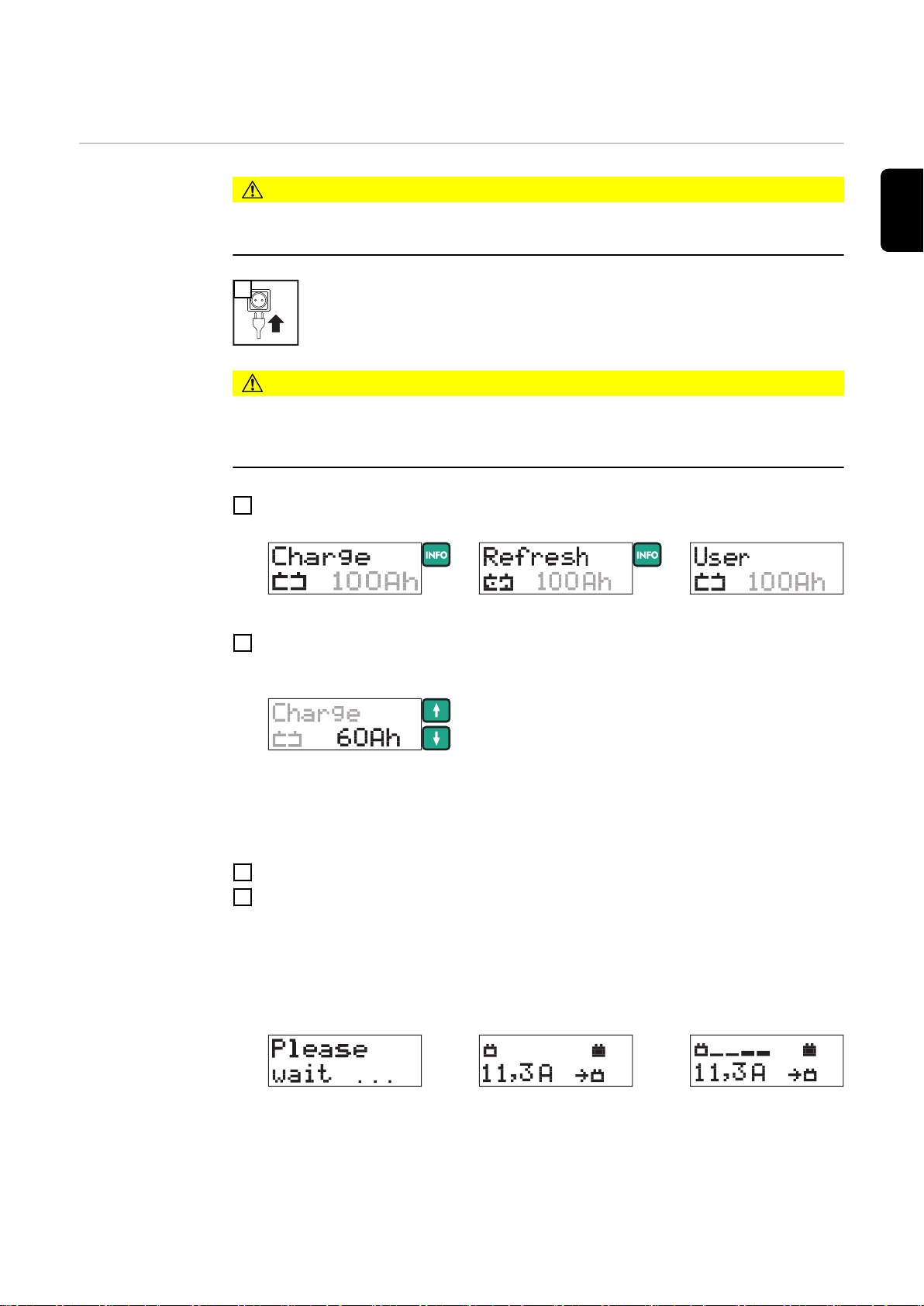
2Select the corresponding operating mode by pressing the info button
Set the capacity of the battery to be loaded using the „up“ and „down“ buttons
3
After the battery capacity has been set, the charging current calculated from this
is shown on the display.
4Connect (+) charging terminal to positive pole on battery
Connect (-) charging terminal to negative pole on the battery, or to vehicle body
5
(e.g. engine block) in the case of vehicle electrical systems.
Charger detects that the battery is connected, carries out a self test and starts
charging.
16
Self test
IMPORTANT! If the battery voltage is < 1.0 V, the battery will not be automatically
detected. Charging must be started manually.
E.g.: charging
Page 17

Retrieving parameters during
charging
1Press the info button during charging
The actual charging current is displayed:
E.g.: actual charging current
By repeated pressing the info button, the other parameters are displayed in the
following sequence:
EN
Deep-discharge
battery: starting
charging manually
E.g.: actual battery
voltage
E.g.: amount of charge fed in E.g.: energy fed in
E.g.: length of time char-
ging so far
The top half of the display shows current progress and the bottom half shows the relevant values.
CAUTION!
Risk of serious damage as a result of incorrectly connected charging terminals.
The reversal polarity protection facility is inoperative if charging is started manually (battery voltage < 1.0 V).
Connect charging terminals to correct poles and ensure proper electrical connection to
vehicle terminals.
1Connect (+) charging terminal to positive pole on battery
Connect (-) charging terminal to negative pole on the battery, or to vehicle body
2
(e.g. engine block) in the case of vehicle electrical systems.
3
Press start/stop button for approx. 5 secs
A query regarding correct polarity of the charging terminals is displayed:
Starting the charging process confirms the correct polarity connection. If there is no
confirmation of correct pole connection within 2.5 secs, the device reverts to menu
mode.
Ensure charging terminals are connected to correct poles
4
5
Start charging by pressing the start/stop button
17
Page 18

The charger starts charging.
Display of charge
progress during
charging
During charging, the number of bars indicates how charging
is progressing.
Final charging stage - once the battery is approx. 80 - 85 %
charged.
- Display shows 6 consecutive bars
- Battery is now ready for use
IMPORTANT! the charger automatically switches over to conservation charging after
approx. 3 - 7 hours, depending on the type of battery. To charge the battery completely,
the battery should remain connected to the charger for this length of time.
NOTE!
Only in Refresh charging mode: When refresh charging has finished, the machine
switches off.
Conservation charging does not take place.
When the battery is fully charged, the charger begins conservation charging.
- all bars are permanently displayed
- The battery is 100 % charged.
- Battery is always ready to use.
- Battery can remain connected to charger for as long as
required.
- Conservation charging counteracts battery selfdischarge.
Interrupting charging / resuming
charging
18
NOTE!
To compensate, the charger can briefly increase the current to the maximum charging current (see Technical Data, user-defined settings in USER menu).
1
Press Start/Stop button to interrupt charging
2
Press Start/Stop button again to resume charging
Page 19

Self test
EN
E.g.: charging continues
Retrieving parameters when
charging has
stopped
Charging was interrupted by pressing the start/stop button.
1Press the info button
The actual charging current is displayed:
E.g.: actual charging current
By repeated pressing the info button, the other parameters are displayed in the
following sequence:
E.g.: actual battery
voltage
E.g.: amount of charge
fed in
E.g.: energy fed in
Finishing charging and disconnecting the battery
E.g.: length of time char-
ging so far
The top half of the display shows < STOP > and the bottom half shows the relevant values.
WARNING!
Risk of explosion due to sparkinhg when disconnecting the charging terminals.
Before disconnecting the charging terminals, stop charging by pressing the start/stop
button and possibly provide adequate ventilation.
1
Finish charging by pressing the start/stop button
19
Page 20

2Disconnect (-) charging terminal from battery
Disconnect (+) charging terminal from battery
3
4
20
Page 21

External power supply
EN
Starting the
external power
supply
1
2
Select FSV/SPLY mode by pressing the info button
3Connect (+) charging terminal to positive pole on battery
Connect (-) charging terminal to negative pole on the battery, or to vehicle body
4
(e.g. engine block) in the case of vehicle electrical systems
Charger detects that the battery is connected, carries out a self test and starts
external power supply.
Self test
- the maximum voltage command value set in
the USER menu is shown in the top half of the
display.
- the current parameters are shown in the bottom half of the display.
By pressing the info button, the parameters are displayed in the following
sequence:
- actual charging current
- actual battery voltage
- amount of charge (Ah) fed in so far
- energy (Wh) fed in so far
- length of time charging so far
IMPORTANT! Start external power supply manually if:
- there is no battery connected to the vehicle
- the battery voltage on the connected battery is < 1.0 V
Starting the
external power
supply manually
CAUTION!
Risk of serious damage as a result of incorrectly connected charging terminals.
The reverse polarity protection facility is inoperative if the external power supply is started manually.
Connect charging terminals to correct poles and ensure proper electrical connection to
vehicle terminals.
21
Page 22

1Connect (+) charging terminal to positive pole on battery
Connect (-) charging terminal to negative pole on the battery, or to vehicle body
2
(e.g. engine block) in the case of vehicle electrical systems
3
press start/stop button for approx. 5 secs
A query regarding correct polarity of the charging terminals is displayed:
Starting the external power supply confirms the correct polarity connection. If the
external power supply is not started within 2.5 secs, the device reverts to menu
mode.
Ensure charging terminals are connected to correct poles
4
5
Start external power supply by pressing the start/stop button
The charger starts the external power supply.
Boost mode If the battery voltage drops while power is being supplied externally because more power
is needed (e.g. because additional consumer loads are switched on), the device goes
into boost mode.
IMPORTANT! To maintain the battery voltage at a constant level, the charger can
increase the current in boost mode to the maximum charging current (see Technical
Data).
To prevent the device overheating, the max. output current can be automatically limited if
the ambient temperature is high (power derating).
Stopping the
external power
supply and dis-
Risk of explosion due to sparkinhg when disconnecting the charging terminals.
WARNING!
connecting the
charging terminals
Before disconnecting the charging terminals, stop external power supply by pressing the
start/stop button and possibly provide adequate ventilation.
22
1
Stop the external power supply by pressing the start/stop button
Page 23

By pressing the info button, the parameters are displayed in the following
sequence:
- actual charging current
- actual battery voltage
- amount of charge (Ah) fed in so far
- energy (Wh) fed in so far
- length of time charging so far
2Disconnect (-) charging terminal from battery
Disconnect (+) charging terminal from battery
3
4
EN
23
Page 24

Charge acceptance test
General Charge acceptance test mode is used to determine a battery’s ability to accept a charge.
The charge acceptance test takes place as follows:
- charge acceptance testing is conducted automatically for a period of 15 minutes; if
the result is positive, the device will then switch automatically to standard charging
mode and charge the battery
- if the result is negative, „Test Fail“ appears on the charger’s screen and charging of
the battery is halted
A prerequisite for a satisfactory charge acceptance test is compliance with EU standard
EN-50342-1:2006 item 5.4 (battery approx. 50% discharged).
Preparations To ensure the battery is about 50% discharged, the following preparations can be carried
out immediately before the charge acceptance test:
Fully charge the battery
1
Calculate the discharge current:
2
Start the charge
acceptance test
battery capacity (Ah)
discharge current =
Charge battery for approx. 5 hours with the calculated discharge current
3
1
2
Select the charge acceptance test mode by pressing the info button
10
Set the capacity of the battery to be tested using the „up“ and „down“ buttons
3
24
4Connect (+) charging terminal to positive pole on battery
(Connect (-) charging terminal to negative pole on the battery, or to vehicle body
5
(e.g. engine block) in the case of vehicle electrical systems
Page 25

Charger detects that the battery is connected, carries out a self-test and starts the
charge acceptance test.
EN
Starting the
charge acceptance test manually
Self test
Charge acceptance test
CAUTION!
Risk of serious damage if the charging terminals are connected incorrectly.
The reverse polarity protection facility is inoperative if the current input test is started
manually (battery voltage < 1.5 V).
Connect charging terminals to correct poles and ensure proper electrical connection to
vehicle terminals.
1Connect (+) charging terminal to positive pole on battery
Connect (-) charging terminal to negative pole on the battery, or to vehicle body
2
(e.g. engine block) in the case of vehicle electrical systems.
3
Press start/stop button for approx. 5 secs
A query regarding correct polarity of the charging terminals is displayed:
Retrieving parameters during the
charge acceptance test
Charge acceptance test finished
- battery OK
Starting the charge acceptance test confirms the correct polarity connection. If
thecharge acceptance test is not started within 2.5 secs, the device reverts to menu
mode.
Ensure charging terminals are connected to correct poles
4
5
Start the charge acceptance test by pressing the start/stop button
The charger starts the charge acceptance test.
By pressing the info button, the parameters are displayed in the following sequence:
- actual battery current
- actual battery voltage
- amount of charge (Ah) fed in so far
- energy (Wh) fed in so far
- time that has elapsed since the start of the test
The battery is OK, when the charger will switch automatically to standard charging mode
and charge the battery after the charge acceptance test has been carried out.
By pressing the Info button stored test parameters and the actual charging parameters
can be viewed:
25
Page 26

- the top half of the display features progress bars to
show the progress of the current charging operation
- the bottom half of the display shows the current charging
E.g.: actual charging current
parameters / calculated test parameters
By repeated pressing the info button, the other parameters are displayed in the following
sequence:
Charging parameters:
E.g.: actual battery voltage E.g.: amount of charge fed in E.g.: energy fed in
E.g.: length of time charging so
far
Charge acceptance test finished
- battery faulty
Test parameters: can be identified by the test symbol
E.g.: charging current E.g.: battery voltage E.g.: set battery capacity
E.g.: Battery’s capacity to accept
charge, expressed in %
IMPORTANT! A fully-charged battery can also return a negative test result. In this case
the battery must be discharged (see chapter entitled Charge acceptance test - Preparations).
The charge acceptance test shows that the battery is faulty. The battery receives no further charge. The result is displayed on the screen:
26
- the top half of the display shows „Test Fail“ at a negative
result of the charge acceptance test
- the bottom half of the display shows the calculated para-
E.g.: charging current
meters
By pressing the Info button the following parameters can be to retrieved:
Page 27

E.g.: battery voltage E.g.: set battery capacity E.g.: Battery’s capacity to accept
charge, expressed in %
If the terminals are disconnected from the battery in this mode, the charger reverts to the
Operating Mode menu.
EN
27
Page 28

Setup menu
General remarks The setup menu gives you the ability to configure the device’s basic settings according to
your own requirements. You can also store frequently used charge settings.
WARNING!
Operating the equipment incorrectly can cause serious damage.
The functions described must only be carried out by trained and qualified personnel. In
addition to the safety rules in these operating instructions, the safety rules of the battery
and vehicle manufacturers must also be followed.
Setup menu overview
USER U/I
Setting of following parameters:
- maximum charging current (standard charging)
- main charging voltage (standard charging)
- conservation charging voltage (standard charging)
- safety cut-out (standard charging)
- maximum charging current (user charging)
- main charging voltage (user charging)
- conservation charging voltage (user charging)
- safety cut-out (user charging)
- maximum external power supply
- external power supply voltage
- refresh charging voltage
- refresh charging period
- exit USER U/I menu
PREFERRED SETTINGS
Saves the frequently used operating modes you wish to
keep once the charger leads are removed or the charger is disconnected from the mains
CHARGING CABLE
Settings defining the length and cross-section of the
charging cable
28
FACTORY SETTING
Resets device to factory setting
DELAY TIME
Sets the charging start delay time. Charging starts after
a predefined period.
DEVICE VERSION
For querying the current hardware and firmware version
DEVICE HISTORY
Checking operating hours counter
EXIT SETUP
Exits the setup menu
Page 29

Accessing setup
menu
1
To access menu: press info button for approx. 5 secs
2
Select menu item using the „up“ and „down“ buttons
3
Enter the selected menu item by pressing the start/stop button
IMPORTANT! If no selection is made within 30 seconds, the setup menu is exited automatically.
EN
Setting parametes in the
USER U/I menu
1
The screen to enter the access code is displayed:
Enter access code 3831:
2
Using the „up“ and „down“ buttons, enter the correct digit in the underlined position
3
Press the info button to go to the next position
Repeat steps 2 and 3 until all four digits have been entered correctly
4
5
Press the start/stop button to confirm the access code is correct
The first parameter in the USER U/I menu is displayed.
Setting parameter - general:
6
Select the desired parameter using the „up“ and „down“ buttons
7
Press the start/stop button
Display flashes.
Adjust the desired value of the selected parameter using the „up“ and „down“ but-
8
tons
9
Press the start/stop button to save the value
29
Page 30

Parameters in the USER U/I menu
maximum charging current (standard charging)
Setting range: see Technical Data, in steps of 0,5 A
main charging voltage (standard charging)
setting range: 12.0 - 15.5 V, in steps of 0.1 V
conservation charging voltage (standard charging)
setting range: Off / 12.0 - 15.5 V, in steps of 0.1 V
IMPORTANT! the conservation charging voltage is only available in Charge mode.
Conservation charging does not take place if conservation charging is set to OFF.
However, if the battery voltage drops below 12 V, charging starts
safety cut-out (standard charging)
setting range: 2 h - 30 h, in 10 min intervals
IMPORTANT! If charging does not end automatically after the set time has elapsed,
the charger will be switched off as a safety precaution.
maximum charging current (user charging)
Setting range: see Technical Data, in steps of 0.5 A
30
main charging voltage (user charging)
setting range: 12.0 - 15.5 V, in steps of 0.1 V
conservation charging voltage (user charging)
setting range: Off / 12.0 - 15.5 V, in steps of 0.1 V
Page 31

IMPORTANT! Conservation charging does not take place if conservation charging is
set to OFF. However, if the battery voltage drops below 12 V, charging starts.
safety cut-out (user charging)
setting range: 2 h - 30 h, in 10 min intervals
IMPORTANT! If charging does not end automatically after the set time has elapsed,
the charger will be switched off as a safety precaution..
maximum external power supply
Setting range: see Technical Data, in steps of 0.5 A
EN
external power supply voltage
setting range: 12.0 - 15.5 V, in steps of 0.1 V
refresh charging voltage
setting range: 12.0 - 17.0 V, in steps of 0.1 V
refresh charging period
setting range: 2 h - 30 h, in 10 min intervals
to exit the USER U/I menu
PRESET menu settining preferred operating
modes
IMPORTANT! To avoid damage to the vehicle electronics, the refresh charging mode
cannot be saved.
1
31
Page 32

2
Select one of the following operating modes using the „up“ and „down“ buttons
Preferred Setting Used Mode (factory setting)
After disconnecting the charging terminals or mains
supply, the last mode selected is saved.
Preferred Setting: charge acceptance test mode
After disconnecting the charging terminals or mains
supply, the charge acceptance test mode is saved.
Preferred Setting: standard charging mode
After disconnecting the charging terminals or mains
supply, the standard charging mode is saved.
Preferred Setting: user charging mode
After disconnecting the charging terminals or mains
supply, the user charging mode is saved.
Preferred Setting: external power supply mode
After disconnecting the charging terminals or mains
supply, the external power supply mode is saved.
3
Save the desired mode by pressing the start/stop button
CHARGING
CABLE menu setting charging
cable data
IMPORTANT! Regardless of the „preferred setting“ saved, another mode can be selec-
ted at any time. After disconnecting the charging terminals or mains supply, the device
automatically reverts to the saved „preferred setting“.
1
The length of the charger cable is displayed.
2
If necessary, change measure (metric/imperial) by pressing the info button
3
To adjust the length of the charger cable press the start/stop button
32
Page 33

The length of the charger cable flashes.
Set the length of the charger cable using the „up“ and „down“ buttons
4
Setting range: 1 to 25 m (3 ft. 3 in. to 82 ft.)
5
To save the length of the charger cable press the start/stop button
6
Select the cross-section of the charger cable using the „up“ and „down“ buttons
7
To adjust the cross-section of the charger cable press the start/stop button
The cross-section of the charger cable flashes.
EN
FACTORY SETTING menu Reset device to
factory setting
Set the the cross-section of the charger cable using the „up“ and „down“ buttons
8
Setting range: 4 - 6 - 10 - 16 - 25 - 35 - 50 mm² (AWG 10 bis AWG 1)
9
To save the cross-section of the charger cable press the start/stop button
10
Select EXIT CH. CABLE using the „up“ und „down“ buttons
11
Press Start/Stop button to exit
1
„Device resetted“ appears for 1 second.
33
Page 34

Device has been reset to factory setting. The submenu is exited automatically.
DELAY TIME
menu - setting
the delay time
1
The delay time flashes.
Set the desired delay time using the „up“ and „down“ buttons
2
Setting range: 0 - 4 h
3
To save the delay time press the start/stop button
IMPORTANT! Delay time must be set again after each cycle. If the power fails, the
countdown stops. Once the power is restored, the countdown continues where it left off.
DEVICE VERSION
menu - viewing
device data
1
2
Select one of the following views using the „up“ and „down“ buttons
Firmware
Displays the firmware version
Boot programm
Displays the boot program version
Hardware
Displays the hardware version installed on the device
Exit
Press start/stop button to exit the DEVICE VERSION
menu
34
Page 35

DEVICE HISTORY
menu - querying
operating hours
1
2
Select one of the following views using the „up“ and „down“ buttons
EN
Operating Hours
Shows the operating hours (device connected to the
mains or switched on)
Charging Hours
Displays the operating time (time during which the
device has been producing power)
Cumulated Ampere Hours
Displays the amount of charge produced
Exit
Press the start/stop button to exit the DEVICE HISTORY menu
35
Page 36

Troubleshooting
Troubleshooting
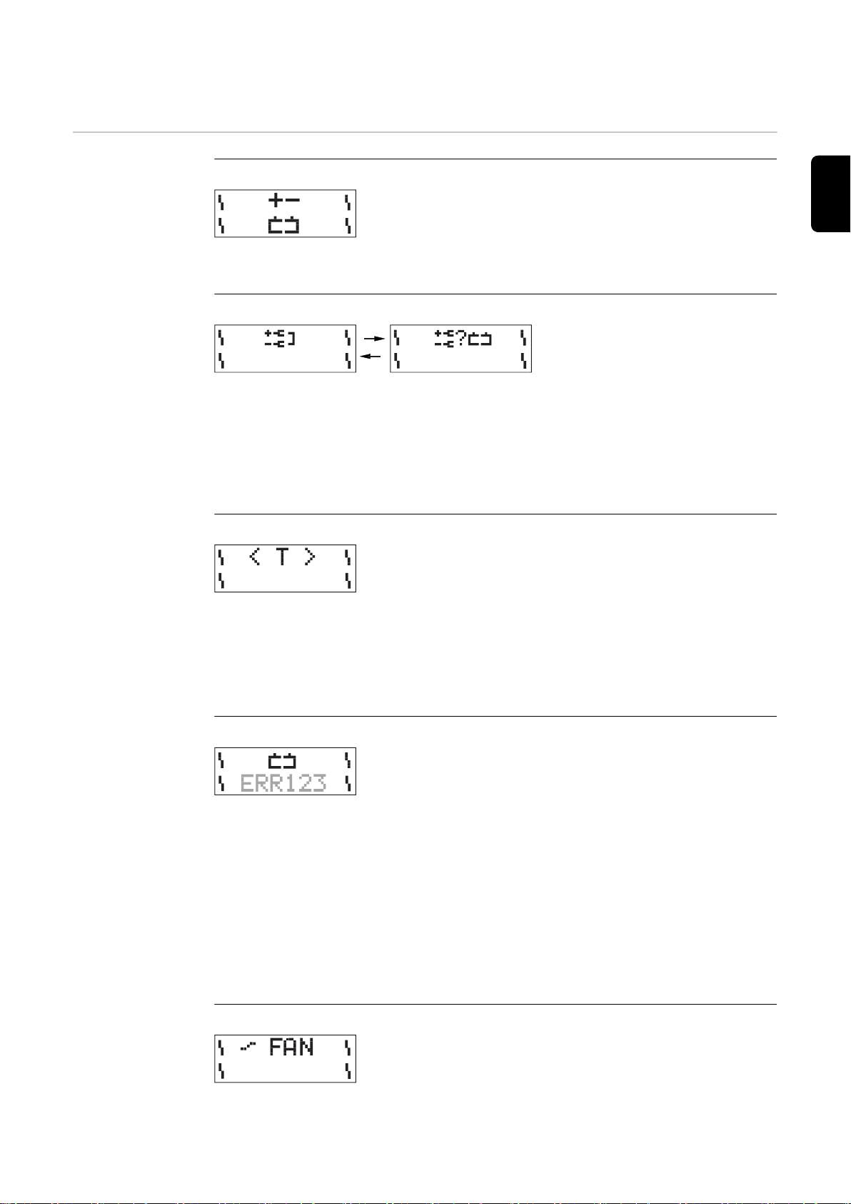
Charging terminals connected to wrong poles
Cause Charging terminals connected to wrong poles
Remedy Swap charging terminals round
Charging terminals short-circuited
Cause Short-circuit on the charging terminals
Remedy Rectify short-circuit on the charging terminals
Cause Battery not detected
Remedy Check that charging terminals are properly connected, press
Start/Stop button for 5 seconds
Over-temperature
Cause Over-temperature - charger too hot
Remedy Allow charger to cool down
Cause Air inlets and outlets covered
Remedy Ensure air inlets and outlets are not obstructed
Safety cut-out
Cause Battery faulty
Remedy Check battery
Cause Charger incorrectly set
Remedy Check settings: Ah, voltage
Cause Incorrect battery type (e.g. NiCd), incorrect number of cells
(voltage)
Remedy Check battery type
Fan blocked/faulty
36
Page 37

Cause Fan blocked
Remedy Check air inlet, remove foreign bodies if necessary
Cause Fan faulty
Remedy Contact specialist dealer
Fuse faulty
Cause Secondary fuse faulty
Remedy Contact specialist dealer
Charger faulty
Cause Charger faulty
Remedy Contact specialist dealer
Nothing on display
EN
Cause Mains supply interrupted
Remedy Connect mains supply
Cause Mains plug or mains cable faulty
Remedy Replace mains plug or mains cable
Cause Charger faulty
Remedy Contact specialist dealer
Charger does not start charging
Cause Charging terminals or charger lead faulty
Remedy Replace charging terminals or charger lead
(M8 nut torque = 15 Nm)
37
Page 38

Symbols used
Warning notices
affixed to the
charger
Follow operating instructions
Connect battery poles correctly:
(+) red (-) black
Detonating gas is generated in the battery during charging.
Risk of explosion!
The charger heats up depending on operating conditions.
Before disconnecting the charger lead from the battery, interrupt charging.
Chargers may only be opened by a qualified electrician
Avoid flames and sparks during charging.
Ensure adequate ventilation during charging.
Battery acid is corrosive.
For indoor use only.
Do not expose to rain.
38
Page 39

Technical data
EN
Acctiva Professional Flash,
Acctiva Professional Flash AUS,
Acctiva Professional Flash JP,
Acctiva Professional 30A JP
Mains voltage (+/- 15%)
Acctiva Professional Flash
Acctiva Professional Flash AUS
Acctiva Professional Flash JP
Acctiva Professional 30A JP
Nominal output max.
Acctiva Professional Flash
Acctiva Professional Flash AUS
Acctiva Professional Flash JP
Acctiva Professional 30A JP
Charging voltage 12,0 - 15,5 V
Charging current I2 (adjustable)
Acctiva Professional Flash
Acctiva Professional Flash AUS
Acctiva Professional Flash JP
Acctiva Professional 30A JP
Boost mode charging current
t
(tI
2 max
Acctiva Professional Flash
Acctiva Professional Flash AUS
Acctiva Professional Flash JP
Acctiva Professional 30A JP
= 30 s, tI2 = 60 s)
2 max
230 V AC, 50/60 Hz
240 V AC, 50/60 Hz
100 V AC, 50/60 Hz
100 V AC, 50/60 Hz
1080 W
1080 W
1080 W
710 W
2 - 50 A
2 - 50 A
2 - 50 A
2 - 30 A
max. 70 A
max. 70 A
max. 70 A
max. 30 A
Nominal charging capacity 10 - 250/300 Ah
Number of cells 6
Charging characteristic IUoU / IUa / IU
Operating temperature * 0 °C to +60 °C
32 °F to 140 °F
Storage temperature -20 °C to +80 °C
4 °F to 176 °F
Interface USB
Climate class (EN50178) B
EMC Class
Acctiva Professional Flash
Acctiva Professional Flash AUS
Acctiva Professional Flash JP
Acctiva Professional 30A JP
Protection IP 20
Marks of conformity see charger rating plate
Weight inclusive of mains and charger
leads
Dimensions w x h x d 315 x 200 x 110 mm
IEC/EN 61000-6-4/2 (EMC class A)
IEC/EN 61000-6-4/2 (EMC class A)
IEC/EN 61000-6-4 (EMC class A)
J 55014
6,5 kg
14.33 lb.
12.40 x 7.87 x 4.33 in.
* If the ambient temperature rises to above 35°C (95°F) or thereabouts (depending
on secondary voltage), the secondary output current is reduced (power derating)
39
Page 40

安全上のご注意
安全通知の説明
警告!
差し迫った危険性があることを示します。
これを回避しないと、死亡や重傷に至ることがあります。
▶
警告!
危険状態になる可能性があることを示します。
これを回避しないと、死亡や重傷に至る可能性があります。
▶
注意!
損傷や傷害が発生するおそれがある状況を示します。
これを回避しないと、軽度の傷害や物体への軽度の損傷が発生するおそれがありま
▶
す。
注記
!
不具合が生じるか、装置を損傷するおそれがあることを示します。
40
Page 41

一般的な注意事項
本充電器は、最先端の技術および認められている安全標準に基づいて、製
造されています。誤ったまたは不適切な使い方により、下記の事故や損傷
が発生するおそれがあります
- 使用者または第三者の傷害や死亡、
- 充電器や作業者の所有物の損傷、
- 充電器の効率低下。
本充電器の始動、操作、整備、修理を実施する人はすべて、下記を満たし
ている必要があります
- 適切な資格を持っており、
- 充電器およびバッテリーの知識および取扱い経験があり、
- これらの取扱説明書を注意深く読みかつこれらに従う。
充電器を使用する場合は、本取扱説明書を常に手近なところに置いてくだ
さい。取扱説明書に加えて、事故防止および環境保護に関する、一般に適
用されている規定およびその地域の規定にも注意してください。
充電器に記載されている安全および危険に関する注記はすべて、
- いつでも読みやすい状態にある必要があり、
- 損傷したり書き込みがされてはならず
- 取り外されてはならず
- 上を覆ったり、上に貼り付けたり、上にペンキを塗ったりしないでく
ださい。
JA
本装置の安全および危険に関する注意事項の記載場所については、装置の
取扱説明書の「一般的な注意事項」を参照してください。
充電器の電源を入れる前に、安全性を損なうおそれのある障害をすべて取
り除いてください。
個人の安全が危険にさらされます。
適切な使用 この装置は、意図された目的のためにのみ使用してください。この目的以外の使用は不
適当とみなされます。そのような誤使用によって発生したいかなる損傷や予期しない結
果または正しくない結果について、当メーカーは責任がないものといたします。
適切に使用するために以下を行ってください。
- 取扱説明書および安全と危険に関する注記をすべて、注意深く読み、遵守する
- 規定された点検および整備作業を実施する
- 電池と車両メーカーの指示のすべてに従う。
装置が適切に機能するには、適切に取り扱うことが必須です。装置を、決してケーブル
で引きまわしてはいけません。
Umgebungsbedin
gungen
主電源接続 より高い規格の装置は、その電流消費のために主要電源のエネルギー品質に影響をあた
Betrieb oder Lagerung des Geräts außerhalb des angegebenen Bereichs gilt als nicht
bestimmungsgemäß. Für hieraus entstandene Schäden haftet der Hersteller nicht.
える場合があります。
41
Page 42

これにより、複数の装置種類に以下の点で影響をあたえる場合があります。
- 接続制限
-
主電源の最大許容電気抵抗に関する基準
-
最低短絡力要件に関する基準
*)
公共送電網との接点
*)
*)
「技術データ」参照
この場合、プラント作業員または装置の使用者は、電力会社と相談の上、適切な場所に
装置が接続されているかどうかを確認します。
重要!グリッド接続が適切に絶縁処理されていることを確かめてください
主電源電流および
充電電流による危
険
酸、ガス、蒸気に
よる危険
充電器を使う人は、次のような多くの危険に身を曝しています:
- 主電源電流および充電電流による感電死の危険。
- 心臓ペースメーカー使用者の生命に危険を及ぼすことがある有害な電磁界。
感電は致命的となる場合があります。どのような感電にも生命を脅かすおそれがありま
す。充電器使用中に感電を避けるには:
- 充電器内部および外側の電気がかかっている部分に触れないでください。
- 絶対にバッテリー電極に触れないでください。
- 充電器リード線や充電器端子を短絡しないでください 。
ケーブル およびリード線はすべて、安全なもので、損傷を受けておらず、絶縁されてお
り、十分なサイズの必要があります。ケーブルおよびリード線を点検して、接続が緩か
ったり、焦げていたり、不十分なサイズの場合には、認定された要員が、直ちに手直し
してください。
バッテリーには、眼や皮膚に有害な酸が、含まれています。充電中に、健康を害する、
あるいはある種の環境下で高度の爆発性のある、ガスや蒸気が放出されます。
充電器は換気の良いところだけで使用し、爆発性ガスの蓄積を避けてください。バッテ
リー コンポーネントは、自然換気または強制換気によって、水素濃度を 4 %未満に保証
できる場合、危険な場所とは見なされません。
バッテリーと充電器の間隔は、充電中常に 0.5 m 以上を確保してください。火気や裸火
のような着火源となるものは、バッテリーに近づけないでください。
42
充電端子のようなバッテリーの接続は、充電中はどのような理由があっても外さないで
ください。
出てきたガスや蒸気は、絶対に吸い込まないようにしてください - その区域の換気が十
分であることを確認してください。
短絡の発生を防ぐため、バッテリー上に工具や導電性の金属を置かないでください。
バッテリーの酸が、眼や皮膚や衣服に付着しないようにしてください。保護ゴーグルお
よび適切な保護服を着用してください。酸の飛沫は、きれいな水で完全に洗い流し、必
要な場合は医療関係者の助言を受けてください。
Page 43

電池の取扱いに関
する基本的情報
- 電池が汚れや機械的損傷を受けないように保護します。
- 充電した電池を涼しい所に保管します。自己放電は、約+ 2℃(35.6℃)で最小に
抑えられます。
- 少なくとも週に 1 回、または電池のメーカーが指定する頻度で目視検査を行い、電
池内の酸(電解質)レベルが最大マークに達していることを確認してください。
- 次のようになっている場合は、本機を始動しないで(既に使用中の場合は直ちに停
止して)、認可されているワークショップで電池を点検します。
- 故障と考えられる原因で、個々の電池の酸のレベルが不ぞろいであるか、水の
消費が多くなった。
- 電池の過熱(55℃/131°F 以上)。
JA
使用者および第三
者の保護
お子様および障害
者による操作
通常運転での安全
対策
充電器を使用中は、全ての人、特に子供を作業区域に入れないでください。ただし、近
くに人がいる場合は、
- その人たちに、有害な酸およびガス、主電源電流および充電電流による危険など、
危険なことの全てについて警告し
- 適切な保護装置で保護します。
作業区域を離れる前に、不在中に人または所有物に危害が加わらないように徹底しま
す。
本装置は 8 歳以上のお子様、および身体的、感覚的または精神的機能に障害のある方、
または経験不足の方にも、監督の下、または装置の使用に関して安全な方法で指示を受
けた場合、かつ関連するリスクについて理解している場合にご利用いただくことができ
ます。お子様が本装置で遊ばないようにしてください。お子様が監督を受けずクリーニ
ングやユーザーメンテナンスを実施することはできません。
- 接地導体付き充電器は、必ず接地導体付き主電源と接地接点付きソケットで使用し
てください。本充電器を PE 導体なしの主電源および接地接点なしのソケットで使
用する場合は、まったくの不注意と見なされます。このような使用によって発生す
るいかなる損傷についても、当メーカーは責任を負いません。
- 本充電器は、定格プレートに記載されている保護の程度を、必ず遵守してご使用く
ださい。
- 何らかの損傷の形跡がある場合は、本充電器を使用しないでください。
- 冷却空気が、充電器の空気ダクトを通って、妨げられずに流入し、流出することを
確認します。
- 主電源および充電器受電部を、認定された電気技師が定期的に点検し、PE 導体が
適切に機能していることを確認するように手配してください。
- 安全器具や部品に、適切に機能していない、あるいは不完全な状態のものがある場
合は、充電器のスィッチを入れる前に、認定された電気技師によって修理する必要
があります。
- 保護装置を迂回したり、無効にしないでください。
- インストール後は、自由にアクセス可能な主電源プラグが必要です。
EMC 装置分類 放出クラス A
- は工業環境での使用のみを目的として設計されていて
- 他の領域では、伝導妨害および放出妨害を引き起こす場合があります。
放出クラス B の装置
- 居住地域および工業地域向けの放出基準を満たしています。これは、電源が、公共
低電源ネットワークによって供給される住宅区域にも適用されます。
EMC 装置分類 (銘板または技術データ参照)
43
Page 44

EMC 対策 装置が標準的な放出限度値に準拠していても、適用対象領域に影響を与える場合があり
ます(例えば、同じ場所に精密機器が置いてあったり、装置が設置された場所が、ラジ
オまたはテレビ受信機の側であった場合)。
この場合、事業会社は適切な行動をとり状態を改善する義務を負います。
データ保護 工場出荷時の設定を変更した場合は、ユーザーが責任を持って、その変更を保持してく
ださい。個々の設定変更が削除された場合、当メーカーは責任を負いません。
整備と修理に関す
る注意事項
保証と責任 充電器の保証期間は請求書の日付から 2 年間です。
通常の使用条件では、本充電器は最少の整備と点検を必要とするだけです。しかし、長
年にわたって使用可能な状態に確実に維持するためには、幾つかの重要な点を遵守する
ことが必須です。
- スィッチを入れる前に必ず、主電源のプラグとケーブル、充電器のリード線/充電
端子に損傷の兆候がないか、点検します。
- 充電器ハウジングの表面が汚れている場合には、軟らかい布に溶剤の入っていない
洗浄剤だけをつけて、拭き取ります。
整備と点検は、認定された要員だけが実施します。純正の交換部品および消耗部品だけ
を(標準部品に適用して)ご使用ください。購入部品が、これに対する要望に適合して設
計および製造されていることや、安全要件を満たしていることは、保証できません。
当メーカーの同意なしに、充電器に改造、変更などを加えないでください。
適用可能な国および地域の規定を順守して、廃棄してください。
しかし、損傷理由が以下の 1 つまたは複数であった場合、当メーカーは一切の責任を負
いません。
- 本充電器を、使用目的に違反して使用。
- 設置や操作が不適切。
- 本充電器に欠陥の保護装置を取り付けて使用。
- 本取扱説明書の内容を不履行。
- 本充電器を、承認を得ずに改造。
- 第三者の行為による災害および不可抗力。
安全検査 当メーカーは、少なくとも 12 ヶ月に 1 回、本装置の安全検査を実施することを推奨し
ます。
認定の電気技師による安全検査を行うことを推奨します。
- 変更の後、
- 改造の後、
- 修理、点検、整備の後、
- 少なくとも 12 ヶ月ごと。
安全検査の場合は、適切な国家規格および国家ガイドラインに従う必要があります。
安全検査についての詳細な情報は、サービスセンターから入手できます。サービスセン
ターは、リクエストに応じて必要な書類を提供します。
廃棄 通常の家庭ごみと一緒に廃棄しないでください!電気および電子装置の廃棄に関する欧
州指令、およびその国内法令としての施行に準拠するため、寿命に達した電気装置は個
別に回収し、認可された再生利用施設に返す必要があります。もはや必要ではない装置
44
Page 45

は、販売業者に返却するか、地域の認可された回収および再生利用施設について調べて
ください。この欧州指令を無視した場合、環境と健康に潜在的な悪影響を与えることが
あります。
Kennzeichnunge
n am Gerät
版権 これらの操作手順の版権は、当メーカーにあります。
Geräte mit CE-Kennzeichnung erfüllen die grundlegenden Anforderungen der
zutreffenden Richtlinien.
Mit EAC-Prüfzeichen gekennzeichnete Geräte erfüllen die Anforderungen der relevanten
Normen für Russland, Weißrussland, Kasachstan, Armenien und Kirgisistan.
本文および説明図はすべて、発行時点で技術的に正確です。弊社は変更する権利を留保
します。本取扱説明書の内容は、購入者からのいかなるクレームにも根拠を与えるもの
ではありません。改善の提案がおありの場合、または説明書で見つかった誤りを指摘し
ていただく場合、弊社はお客様のコメントに大変感謝いたします。
JA
45
Page 46

一般事項
安全
警告!
むき出しで回転している自動車部品に触れると、ケガしたり、損傷したりする恐れがあ
ります。
自動車のエンジン コンパートメントで作業中は、手、髪、衣服の一部や充電器リード線
が、ファンベルト、ファンなどの動いている部品に触れないように注意してください。
注意!
モードを間違って設定すると、製品が破損したり、充電の性能が落ちることがありま
す。必ず充電するバッテリーの種類に合わせてモードを設定してください。
充電器を安全に取り扱うために、次の保護装置が装備されています。
- バッテリーに接続するときに、未接続状態の端子の間で火花放電しないようにする
保護
- 充電端子の短絡、極性反転に対する保護
- 充電器の過熱抑止
注記
!
過放電バッテリーに対しては、極性反転保護機能が作動しません。バッテリー電圧が低
すぎると (1.
0 V 未満)、充電器はバッテリーが接続されているかどうかを認識できなくなります。手
動で充電を開始する前に、充電端子が正しい電極に接続されていることを確認してくだ
さい。
「使用目的」に適
合した使用
使用されているシ
ンボル
この充電器は次の種類のバッテリーの充電だけに使用してください:
液体電解質 (鉛、ゲル、カルシウム、カルシウム銀) または
- 固体電解質(AGM、MF、シーラント)を用いる鉛酸蓄バッテリー
重要!重要! 乾電池 (一次電池) をこの充電器で充電すると「使用目的に違反する」と見
なされます。このような不適切な使用によって発生するいかなる損傷についても、当メ
ーカーは責任を負いません。
主電源スイッチがある装置
- 主電源装置のスイッチをオフにします
- 装置を主電源から外します
主電源スイッチがない装置
- 装置を主電源から外します
主電源スイッチがある装置
- 装置を主電源に接続します
- 装置の主電源スイッチをオンにします
主電源スイッチがない装置
- 装置を主電源に接続します
46
Page 47

コントロールエレメントおよび接続部
(1)
(2)
(3) (4) (5) (6)
(4)
(5)(7)
(8)(9)
一般的な注意事項
制御と接続
注記
!
ファームウェアを更新すると、この取扱説明書に記載されていない機能が使用できるよ
うになったり、記載されている機能が使用できなくなることがあります。また、特定の
図が、装置の実際のコントロールと多少異なることがあります。ただし、これらのコン
トロールは説明されているとおりに機能します。
(1) (+) 充電端子スクリュー コネクタ
(2) (-) 充電端子スクリュー コネクタ
(3) USB ポート用カバー
(4) (-) 充電端子 - 黒色
(5) (+) 充電端子 - 赤色
(6) ファームウェア更新用の
USB ポート。
詳細はホームページをご覧くださ
い
http://www.fronius.com
JA
正面図
(7) 多機能パネル
(8) 主電源スイッチがある装置
(9) 主電源のケーブルとプラグ
背面図
47
Page 48

(10)(14) (13) (12) (11)
多機能パネル
(10) 情報ボタン
望ましいモードに設定し
充電中に充電パラメーターを読み
出します。
(11) [Start/Stop(開始/停止)] ボタン
充電の中断および再開
(12) [Down(下へ)]ボタン
(13) [Up(上へ)]ボタン
(14) ディスプレイ
48
Page 49

取付けオプション
2
1
4
3
1
2
オプションのエッ
ジガードの取付け
装置に合わせて固有のエッジガードを取り付けます。
重要!充電器を壁に取り付けるとき、取り付けツールはエッジガードがあることを前提
としているため、必ずエッジガードを取り付けてください。
充電器を床に設置する場合は、エッジガードを取り付けないでください。
エッジガードの取付け:
1
JA
2
重要!エッジガードを恒久的に取り付ける場合、粘着ストリップのカバーストリップを
剥がします。
壁への取付け オプションの壁用ブラケットを使用して、充電器を壁に取り付けます:
注記
!
充電器を壁に取り付ける場合、充電器の重量に注意してください。目的に適した場合に
限り壁に取り付けてください。
49
Page 50

1
370 mm
42 mm
- ドウェルおよびスクリューを使用し
て、壁用ブラケットを適切な壁面に固
定します。
- 充電器の底面が壁用ブラケット
の面にしっかりと合わさっている必要
があります。
- 充電器を恒久的に壁用ブラケットに取
り付ける場合のみ:
お届けした 2 個のスクリュー(直径
3.5 x 9.5 mm)を使用して充電器をブ
ラケットに固定します。
床への取付け オプションの取付けブラケットを使用して、充電器を床に取り付けます。
取付けブラケットを充電器正面パネル
1
の通気グリルの両側に差し込み、背面
パネルにも同様に差し込みます。
取付け面の穴位置にマーキングを付け
2
ます (寸法図を参照)
穴を開けます
3
取付け面 (直径 5mm) の性質に合わせ
4
て、最適な充電器用締付けスクリュー
を選択します
取付けブラケット 1 個ごとに 2 個の
5
スクリューを使用して、取付け面に充
電器を締め付けます。
50
Page 51

操作モード
使用可能な操作モ
ード
使用可能な操作モードの概要は次のとおりです。
個々のモードに関する重要な追加情報は、次のセクションに記載されています。
JA
標準充電
- 液体電解質 (鉛、ゲル、カルシウム、カルシウム銀)を用
いるバッテリー向け
- 固体電解質(AGM、MF、シーラント)を用いるバッテ
リー向け
リフレッシュ充電
- 液体電解質 (鉛、ゲル、カルシウム、カルシウム銀) を
用いるバッテリーの再活性用
- 固体電解質(AGM、MF、シーラント)を用いるバッテ
リーの再活性用
ユーザー充電
- 液体電解質 (鉛、ゲル、カルシウム、カルシウム銀) を
用いるバッテリー向けの更なる充電モード
- 固体電解質(AGM、MF、シーラント)を用いるバッテ
リー向けの更なる充電モード
外部電源
消費者への外部電源の供給と、自動車用バッテリーのバック
アップ
充電受容テスト
標準充電モード 以下の場合、標準充電モードをご利用ください:
- 取り付けられた、または取り外されたバッテリーへの充電/保護充電
- トリクルモード (車両内の負荷機器のスイッチを入れたとき、バッテリーを充電す
るため)
リフレッシュ充電
モード
車輌搭載電子機器がリフレッシュ充電によって破損する恐れがあります。リフレッシュ
充電を開始する前に、バッテリーを車輌電源から外してください。
バッテリーが長時間、過放電していたと思われる (バッテリーが硫化しているなど) 場合
は、リフレッシュ充電モードをバッテリーの充電に使用してください。
- バッテリーは最大酸濃度まで充電されます。
- 電極板を再活性化します (硫化層の分解)
注意!
重要!リフレッシュ充電の成否は、バッテリーに蓄積されている硫酸鉛の量によって左
右されます。
51
Page 52

注記
!
リフレッシュ充電を使用できるのは以下の条件に適合している場合のみです。
バッテリー容量が正しく設定されていること
▶
リフレッシュ充電が十分に換気された場所で行われること
▶
ユーザー充電モードユーザー充電モードは追加の充電モードで、装置の充電パラメーターを個別に指定する
ことができます。
ユーザー充電モードのパラメーターは、予備アプリケーション(非常用電源システムな
ど)または周囲温度> 35°C(95°F)向けに、事前に工場で設定されています。
ユーザー充電モードは以下の場合に使用します:
- 取り付けられた、または取り外されたバッテリーへの充電/保護充電
- トリクルモード (車両内の負荷機器のスイッチを入れたとき、バッテリーを充電す
るため)
External power
supply mode
充電受容テストモ
ード
外部電源モードでは、下記の場合にも、負荷機器に確実に電力を供給します
- 消費電力が増加したとき (車輌搭載電子機器用ファームウェア/ソフトウェアの更新
など)
- バックアップモードで、バッテリーが充電中に、車載搭載電子システムに電源を供
給するため(時計、ラジオなどの設定を消さないため)
充電受容テストモードは、バッテリーが充電を受容する機能をテストするために使用し
ます。テストは以下のように行います:
- 自動充電受容テストには数分しかかかりません。
- 充電受容テストは事前に定めた時間が経過すると終了します。
- 結果が良好な場合、装置は自動的に標準充電モードに切り替わり、バッテリーを充
電します。
- 結果が不良な場合、「テスト失敗」が充電器のスクリーンに表示され、バッテリー
の充電は停止します。
52
Page 53
バッテリー充電
充電の開始
注意!
故障したバッテリーを充電すると、損傷する危険があります。充電する前に、充電しよ
うとするバッテリーが問題なく使用できることを確認します。
1
注意!
リフレッシュ充電を選択した場合:リフレッシュ充電により車載搭載電子機器が損傷す
るリスクがあります。
リフレッシュ充電を開始する前に、バッテリーを車輌電源から外してください。
2[info(情報)] ボタンを押して、対応する操作モードを選択します。
JA
[up(上へ)]および[down(下へ)]ボタンで、充電されるバッテリーの容量を設定しま
3
す。
バッテリー容量を設定すると、計算された充電電流がディスプレイに表示されま
す。
4(+)充電端子を、バッテリーの正極に接続します
(-)充電端子を、バッテリーの負極、または車輌電源システムの場合は車輌の車体
5
(エンジン ブロックなど)に、接続します
充電器は、バッテリーが接続されていることを認識して、セルフテストを実行
し、充電を開始します。
セルフテスト
重要! バッテリー電圧が 1.0 V より小さいと、バッテリーは自動的には認識されませ
ん。充電を手動で開始する必要があります。
例:充電中
53
Page 54

充電中のパラメー
タの読み出し
1充電中に[info(情報)] ボタンを押します
実際の充電電流が表示されます。
例:実際の充電電流
[info(情報)] ボタンを再度押すと、他のパラメーターが以下の順番で表示され
ます。
長時間過放電して
いたバッテリー:
手動で充電を開始
します
例: 現在のバッテリー
電圧
例:送り込まれた充電量 例:送り込まれたエネル
ギー
例:これまでの充電時間
ディスプレイの上半分には現在の進捗が、下半分には関連値が表示されます。
注意!
充電端子を間違って接続すると、重大な損傷を起こす危険があります。充電を手動で開
始した (バッテリー電圧が 1.
0 V 未満 場合には、極性反転保護機能が無効になります。
充電端子を正しい電極に接続して、車輌端子に電子的に正しく接続されていることを確
認します。
54
1(+)充電端子を、バッテリーの正極に接続します
(-)充電端子を、バッテリーの負極、または車輌電源システムの場合は車輌の車体
2
(エンジン ブロックなど)に、接続します
[Start/Stop (開始/停止)] ボタンを約 5 秒間押します
3
充電端子の極性が正しいかどうか確認する質問が表示されます。
充電プロセスを開始して、正しい極性接続であることを確認します。2.5 秒以内
に、現在正しい電極に接続されていることが確認されない場合、装置はメニュー
モードに戻ります。
充電端子が正しい電極に接続されていることを確認します
4
[Start/Stop (開始/停止)] ボタンを押して充電を開始します
5
Page 55

充電器が充電を開始します。
JA
充電中の充電の進
行状況の表示
充電中にバーの数で充電の進行状況が分かります。
バッテリーが約 80~85% 充電されると、最終充電段階にな
ります。
- 6 本のバーがディスプレイに表示されます。
- バッテリーが使用可能になりました
重要! バッテリーの種類によって異なりますが、充電器で約 3~7 時間充電すると、自
動的に保護充電に切り替わります。バッテリーを完全に充電するには、このぐらいの長
さの時間、バッテリーを充電器に接続しておく必要があります。
注記
!
フレッシュ充電モードの場合のみ、フレッシュ充電が終了したとき、本機のスイッチが
切れます。保護充電は実行されません。
バッテリーが完全に充電されると、充電器は自動的に保護充
電を開始します。
- すべてのバーが恒久的に表示されます。
- バッテリーが 100% 充電されました
- バッテリーが常時、使用可能になりました
- バッテリーはできるだけ長く充電器に接続しておきます
- 保護充電によってバッテリーの自己放電分が補充されま
す
充電の中断/充電の
再開
注記
!
これを補正するために、充電器の電流が一時的に最大充電電流値まで上昇します (「技
術仕様の [USER] メニューのユーザー定義の設定」を参照)。
1[Start/Stop (スタート/ストップ)] ボタンを押して、充電を中断します
2[Start/Stop (スタート/ストップ)] ボタンを押して、充電を再開します
セルフテスト
例:充電の継続
55
Page 56

充電停止時のパラ
メータの読み出し
[Start/Stop (開始/停止)] ボタンを押すと充電は中断します
1[info(情報)] ボタンを押します
実際の充電電流が表示されます。
例:実際の充電電流
[info(情報)] ボタンを再度押すと、他のパラメーターが以下の順番で表示され
ます。
充電の完了とバッ
テリー接続の切断
例: 現在のバッテリー
電圧
例:送り込まれた充電量
例:送り込まれたエネル
ギー
例:これまでの充電時間
ディスプレイの上半分には< STOP(停止)>が、下半分には関連値が表示されます。
警告!
充電端子の接続を外す際の火花による爆発のリスク。
充電端子の接続を外す前に、[Start/Stop (スタート/ストップ)] ボタンを押して充電を停
止し、適切な換気をしてください。
1[Start/Stop (開始/停止)] ボタンを押して充電を完了します
56
2バッテリーの(-) 充電端子の接続を外します
バッテリーの(+) 充電端子の接続を外します
3
4
Page 57

外部電源
外部電源からの充
電開始
1
2[info(情報)] ボタンを押して、FSV/SPLY モードを選択します。
3(+)充電端子を、バッテリーの正極に接続します
(-)充電端子を、バッテリーの負極、または車輌電源システムの場合は車輌の車体
4
(エンジン ブロックなど)に、接続します
充電器は、バッテリーが接続されていることを認識して、セルフテストを実行
し、外部電源からの充電を開始します。
セルフテスト
JA
外部電源からの手
動充電開始
- USER メニューに設定されている最大電圧コ
マンド値が、ディスプレイの上半分に表示さ
れます。
- 電流パラメーターはディスプレイの下半分に
表示されます。
[info(情報)] ボタンを再度押すと、他のパラメーターが以下の順番で表示され
ます。
- 実際の充電電流
- 実際のバッテリー電圧
- これまで送り込まれた充電量 (Ah)
- これまで送り込まれたエネルギー (Wh)
- これまでの充電時間
重要! 外部電源からの充電を手動で開始します:
- 車輌にバッテリーが接続されていない
- 接続されているバッテリーの電圧が 1.0 V 以下
注意!
充電端子を間違って接続すると、重大な損傷を起こす危険があります。外部電源からの
充電を手動で開始した場合は、極性反転保護機能が無効になります。
充電端子を正しい電極に接続して、車輌端子に電子的に正しく接続されていることを確
認します。
57
Page 58

1(+)充電端子を、バッテリーの正極に接続します
(-)充電端子を、バッテリーの負極、または車輌電源システムの場合は車輌の車体
2
(エンジン ブロックなど)に、接続します
[Start/Stop (開始/停止)] ボタンを約 5 秒間押します
3
充電端子の極性が正しいかどうか確認する質問が表示されます。
外部電源を開始して、正しい極性接続であることを確認します。2.5 秒以内に、外
部電源を開始しないと、装置はメニューモードに戻ります。
充電端子が正しい電極に接続されていることを確認します
4
[Start/Stop (開始/停止)] ボタンを押して外部電源を開始します
5
充電器が外部電源を開始します。
ブーストモード 電力を外部に供給している間に、より多くの電力が必要なためバッテリー電圧が低下す
る場合は(例:他の機器を使用している)、装置はブーストモードになります。
重要!バッテリー電圧を一定に維持するため、充電器はブーストモードの電流を最大充
電電流まで引き上げます(「技術仕様」参照)。
装置の過熱を防ぐため、周囲温度が高い場合、最大出力電流は自動的に制限されます(電
力負荷軽減)。
外部電源を停止
し、充電端子の接
続を外します
充電端子の接続を外す際の火花による爆発のリスク。
警告!
充電端子の接続を外す前に、[Start/Stop (スタート/ストップ)] ボタンを押して外部電源
を停止し、適切な換気をしてください。
1[Start/Stop (開始/停止)] ボタンを押して外部電源を停止します。
58
Page 59

[info(情報)] ボタンを再度押すと、他のパラメーターが以下の順番で表示され
ます。
- 実際の充電電流
- 実際のバッテリー電圧
- これまで送り込まれた充電量 (Ah)
- これまで送り込まれたエネルギー (Wh)
- これまでの充電時間
2バッテリーの(-) 充電端子の接続を外します
バッテリーの(+) 充電端子の接続を外します
3
4
JA
59
Page 60

充電受容テスト
概要 充電受容テストモードは、バッテリーが充電を受容する機能を測定するために使用しま
す。
充電受容テストは以下のように行います:
- 充電受容テストは自動で 15 分間行われます:結果が良好な場合、装置は自動で標
準充電モードに切り替わり、バッテリーを充電します。
- 結果が不良な場合、「テスト失敗」が充電器のスクリーンに表示され、バッテリー
の充電は停止します。
充電受容テストの要件は、EU 基準 EN-50342-1:2006 項目 5.4 (約 50%過放電したバッ
テリー)に準拠しています。
準備 バッテリーが確実に約 50%放電するように、充電受容テストの直前に以下の準備を行い
ます:
バッテリーを完全に充電
1
放電電流の計算
2
充電受容テストを
開始します
バッテリー容量 [Ah]
放電電流 =
計算された放電電流でバッテリーを約 5 時間充電します
3
1
10
2[info(情報)] ボタンを押して、充電受容テストモードを選択します。
[up(上へ)]および[down(下へ)]ボタンで、テストされるバッテリーの容量を設定しま
3
す。
60
4(+)充電端子を、バッテリーの正極に接続します
(-)充電端子を、バッテリーの負極、または車輌電源システムの場合は車輌の車体
5
(エンジン ブロックなど)に、接続します
Page 61

充電器は、バッテリーが接続されていることを認識して、セルフテストを実行
し、充電受容テストを開始します。
充電受容テストを
手動で開始する
セルフテスト
充電受容テスト
注意!
充電端子を間違って接続すると、重大な損傷を起こす危険があります。電流入力テスト
を手動で開始した (バッテリー電圧が 1.
5 V 未満)場合には、極性反転保護機能が無効になります。
充電端子を正しい電極に接続して、車輌端子に電子的に正しく接続されていることを確
認します。
1(+)充電端子を、バッテリーの正極に接続します
(-)充電端子を、バッテリーの負極、または車輌電源システムの場合は車輌の車体
2
(エンジン ブロックなど)に、接続します
[Start/Stop (開始/停止)] ボタンを約 5 秒間押します
3
充電端子の極性が正しいかどうかという質問が表示されます。
JA
充電受容テスト中
に、パラメーター
を読み出します
充電受容テストが
終了し、バッテリ
ーに問題はありま
せん。
充電受容テストを開始して、正しい極性接続であることを確認します。2.5 秒以内
に、充電受容テストを開始しないと、装置はメニューモードに戻ります。
充電端子が正しい電極に接続されていることを確認します
4
[Start/Stop (開始/停止)] ボタンを押して充電受容テストを開始します
5
充電器が充電受容テストを開始します。
[info(情報)] ボタンを再度押すと、他のパラメーターが以下の順番で表示されます。
- 実際のバッテリー電圧
- 実際のバッテリー電圧
- これまで送り込まれた充電量 (Ah)
- これまで送り込まれたエネルギー (Wh)
- テスト開始からの経過時間
充電受容テストを実行した後で、充電器が自動的に標準充電モードに切り替わりバッテ
リーを充電すれば、バッテリーに問題はありません。
[info(情報)] ボタンを押すと、保存したテストパラメーターと、実際の充電パラメー
ターとを閲覧できます。
例:実際の充電電流
- ディスプレイの上半分に進行状況を示すバーが現われ、
充電作業の現在の進捗を示します。
- ディスプレイの下半分に現在の充電パラメーター/計算
されたテストパラメーターを示します。
61
Page 62

[info(情報)] ボタンを再度押すと、他のパラメーターが以下の順番で表示されます。
充電パラメーター
例: 現在のバッテリー電圧 例:送り込まれた充電量 例:送り込まれたエネルギー
例:これまでの充電時間
テストパラメーター:テスト記号で判断できます。
例:充電電流 例:バッテリー電圧 例:バッテリー容量の設定
充電受容テスト終
了-バッテリーに
欠陥あり
例:充電を受容可能なバッテリー
の容量、%で表示
重要!完全に充電されたバッテリーもネガティブなテスト結果を示す場合があります。
この場合、バッテリーは放電しています(充電受容テスト - 準備の章をご覧ください)。
充電受容テストは、バッテリーに欠陥があることを示します。バッテリーはそれ以上充
電されません。結果はスクリーンに表示されます:
- ディスプレイの上半分に充電受容テストの結果がネガテ
ィブなため『テスト失敗』と表示されます。
- ディスプレイの下半分に、計算されたパラメーターが表
例:充電電流
示されます。
[Info (情報)] ボタンを押して、次のパラメータを読み出します:
62
例:バッテリー電圧 例:バッテリー容量の設定 例:充電を受容可能なバッテリー
の容量、%で表示
このモードでバッテリーの充電端子の接続を外す場合、充電器は操作モードメニューに
戻ります。
Page 63

設定メニュー
一般的な注意事項 設定メニューで、ユーザーの必要条件に合わせて装置の基本設定を構成できます。頻繁
に使用する充電設定を保存することも可能です。
警告!
装置を間違って操作すると、重大な損傷を起こしかねません。記載されている機能はト
レーニングを受けて、資格を持つ技術者だけが実行してください。この取扱説明書の安
全上の注意事項に加えて、バッテリーや車輌の製造元が規定している安全上の注意事項
も遵守してください。
JA
設定メニュー - 概
要
ユーザー U/I
以下のパラメーターの設定:
- 最大充電電流(標準充電)
- 主電源充電電圧(標準充電)
- 保護充電電圧(標準充電)
- 自動電源遮断(標準充電)
- 最大充電電流(標準充電)
- 主電源充電電圧(ユーザー充電)
- 保護充電電圧(ユーザー充電)
- 自動電源遮断(ユーザー充電)
- 最大外部電源
- 外部電源電圧
- リフレッシュ充電電圧
- リフレッシュ充電期間
- USER U/I メニューを終了
好ましい設定
充電器リード線が外されるか、充電器が主電源から外
されても保持しておきたい、頻繁に使用される操作モ
ードを保存します。
充電ケーブル充電用ケーブルの長さと導体断面積を定
義します。
出荷時設定
装置を工場出荷時の設定にリセットします。
遅延時間
充電開始遅延時間を設定します。充電は、事前設定さ
れた時間の経過後に開始されます。
装置のバージョン
現在のハードウェアとファームウェアのバージョンの
照会に使用します。
装置の履歴
操作時間カウンタの確認に使用します。
終了設定
設定メニューを終了します。
63
Page 64

設定メニューへの
アクセス
メニューにアクセスするには:[Info (情報)] ボタンを約 5 秒間押します。
1
[up(上へ)]および[down(下へ)]ボタンでメニュー項目を選択します。
2
[Start/Stop (開始/停止)] ボタンを押して選択したメニュー項目を入力します
3
重要! 30 秒以内に何も選択されない場合、設定メニューは自動的に終了します。
[User U/I ] メニ
ューのパラメータ
ーを設定します。
1
アクセスコードを入力するスクリーンが表示されます。
アクセスコード 3831 を入力します。
『上へ』『下へ』キーを使用して、下線の付いた位置に適正な数字を入力します
2
[Info (情報)] ボタンを押して、次の位置に移動します
3
4 桁すべての数字が正確に入力されるまでステップ 2 および 3 を繰り返します
4
[Start/Stop (スタート/ストップ)] ボタンを押して、アクセスコードが正しいことを
5
確認します
64
USER/UI メニューの最初のパラメーターが表示されます。
パラメーターの設定 - 全般:
[up(上へ)]および[down(下へ)]ボタンを使ってパラメーターを選択します。
6
[Start/Stop (スタート/ストップ)] ボタンを押します
7
ディスプレイが点滅します。
[up(上へ)]および[down(下へ)]ボタンで選択したパラメーターの値を調整します。
8
[Start/Stop (開始/停止)] ボタンを押して、値を保存します。
9
[User U/I ] メニューのパラメーター
Page 65

最大充電電流(標準充電)設定範囲:0,5 A のステップにある
[Technical Data(テクニカルデータ)]をご覧ください
主電源充電電圧(標準充電)設定範囲:0.1 V のステップ
で
は、12.0-15.5 V
保護充電電圧(標準充電)設定範囲:オフ/0.1 V のステッ
プでは 12.0-15.5 V
JA
重要!保護充電電圧は充電モードにおいてのみ使用可能です。保護充電をオフに設定
した場合、保護充電は行われません。ただし、バッテリー電圧が 12V 以下に降下した
場合、充電が開始されます。
自動電源遮断(標準充電)設定範囲:10 分間隔で、2 時
間-30 時間
重要!設定時間が経過しても充電が自動的に終了しない場合、安全対策として充電器
のスイッチが切れます。
最大充電電流(標準充電)設定範囲:0.5 A のステップに
ある[Technical Data(テクニカルデータ)]をご覧くだ
さい
主電源充電電圧(ユーザー充電)設定範囲:0.1 V のステ
ップでは、12.0-15.5 V
保護充電電圧(ユーザー充電)設定範囲:オフ/0.1 V のス
テップでは 12.0-15.5 V
65
Page 66

重要!保護充電をオフに設定した場合、保護充電は行われません。ただし、バッテリ
ー電圧が 12V 以下に降下した場合、充電が開始されます。
自動電源遮断(ユーザー充電)設定範囲:10 分間隔で、2
時間-30 時間
重要!設定時間が経過しても充電が自動的に終了しない場合、安全対策として充電器
のスイッチが切れます。
最大外部電源設定範囲:0.5 A のステップにある
[Technical Data(テクニカルデータ)]をご覧ください
外部電源電圧設定範囲:0.1 V のステップでは、12.0-15.5
V
充電電圧設定範囲の再読み込み:0.1 V のステップでは
12.0-17.0 V
充電期間設定範囲の再読み込み:10 分間隔で、2 時間-30
時間
[User U/I ] メニューを終了する方法
[PRESET(事前設
定)]メニュー - お
好きな操作モード
を設定します。
66
重要!車輌電子部品の損傷を回避するため、リフレッシュ充電モードは保存できませ
ん:
1
Page 67

[up(上へ)]および[down(下へ)]ボタンで、以下の操作モードから1つ選択します。
2
優先設定(出荷時設定)
充電端子や主電源の接続を切断すると、最後に選択さ
れていたモードが保存されます。
優先設定: 充電受容テストモード
充電端子や主電源の接続を切断すると、充電受容テス
トモードが保存されます。
優先設定: 標準充電モード
充電端子や主電源の接続を切断すると、標準充電モー
ドが保存されます。
優先設定: ユーザー充電モード
充電端子や主電源の接続を切断すると、ユーザー充電
モードが保存されます。
優先設定:外部電源モード充電端子や主電源の接続が
外されると、外部電源 モードが保存されます。
[Start/Stop (開始/停止)] ボタンを押してお望みのモードを保存します
3
JA
充電器ケーブルメ
ニュー - 充電ケー
ブルデータの設定
重要!保存されている「優先設定」に関係なく、いつでも他のモードを選択できます。
充電端子や主電源の接続を切断すると、装置は保存されている「優先設定」に自動的に
戻ります。
1
充電器ケーブルの長さが示されます。
必要に応じて、[Info (情報)] ボタンを押して、寸法の単位 (メートル法または英国標
2
準) を変更します
ケーブルの長さを調整するには、[Start/Stop (開始/停止)] ボタンを押します。
3
充電器ケーブルの長さが点滅します。
67
Page 68

[up(上へ)]および[down(下へ)]ボタンで充電器ケーブルの長さを設定します
4
設定範囲:1~25 m (3 ft. 3 in.~ 82 ft.)
充電器ケーブルの長さを保存するには、[Start/Stop (開始/停止)] ボタンを押しま
5
す。
[up(上へ)]および[down(下へ)]ボタンで充電器ケーブルの導体断面積を選択します。
6
充電器ケーブルの導体断面積を調整するには、[Start/Stop (開始/停止)] ボタンを押
7
します。
充電器ケーブルの導体断面積が点滅します。
出荷時設定メニュ
ー - 装置を出荷時
設定にリセットし
ます
[up(上へ)]および[down(下へ)]ボタンで充電器ケーブルの導体断面積を設定します。
8
設定範囲:4、6、10、16、25、35、50 mm2 (AWG 10 ~ AWG 1)
充電器ケーブルの導体断面積を保存するには、[Start/Stop (開始/停止)] ボタンを押
9
します。
[up(上へ)]および[down(下へ)]ボタンで EXIT CH. CABLE を選択します。
10
[Start/Stop (スタート/ストップ)] ボタンを押して、終了します
11
1
「Device resetted? (装置をリセットしましたか)」が 1 秒間表示されます。
68
装置が工場出荷時の設定にリセットされます。サブメニューは自動的に終了しま
す。
Page 69

遅延時間メニュー
- 遅延時間を設定
します
1
遅延時間が点滅します。
[up(上へ)]および[down(下へ)]ボタンで望みの遅延時間を設定します
2
設定範囲:0~4 時間。
遅延時間を保存するには、[Start/Stop (開始/停止)] ボタンを押します。
3
重要!遅延時間はサイクルごとに設定してください。停電の場合、カウントダウンが停
止します。電源が復旧したら、最後の数値からカウントダウンが再開されます。
JA
[DEVICE
VERSION (装置の
バージョン)] メニ
ュー - 装置データ
の閲覧
1
[up(上へ)]および[down(下へ)]ボタンで以下からビューを選択します。
2
ファームウェア
ファームウェアのバージョンを表示します。
ブートプログラム
ブートプログラムのバージョンを表示します。
ハードウェア
装置にインストールされているハードウェアのバージ
ョンを表示します。
終了
[Start/Stop (開始/停止)] ボタンを押して、[DEVICE
VERSION (装置のバージョン)] メニューを終了しま
す。
装置の履歴メニュ
ー - 操作時間を確
認します
1
69
Page 70

[up(上へ)]および[down(下へ)]ボタンで以下からビューを選択します。
2
操作時間
運転時間を表示します (主電源に接続されている装置ま
たはスイッチがオンになっている装置).
充電時間
運転時間を表示します (装置が電力を発生してきた時
間)。
累積アンペア時間
発生した充電量を表示します。
終了
[Start/Stop (開始/停止)] ボタンを押して、[DEVICE
HISTORY(装置の履歴)] メニューを終了します。
70
Page 71
トラブルシューティング
トラブルシューテ
ィング
充電端子が間違った電極に接続されています。
原因: 充電端子が間違った電極に接続されています。
対策: 充電端子を相互に差し替えます。
充電端子が短絡した
原因: 充電端子で短絡が発生しました。
対策: 充電端子の短絡部を修正します。
原因: バッテリーが認識されていません。
対策: 充電端子が適正に接続されているか確認し、5 秒間、[Start/
Stop (開始/停止)] ボタンを押します。
過熱
JA
原因: 充電器が過熱されて熱くなりすぎています。
対策: 充電器が冷えるまで放置します。
原因: 吸気口と排気口が塞がれています。
対策: 吸気口と排気口から障害物を取り除きます。
自動電源切断装置
原因: バッテリーが故障しています。
対策: バッテリーを点検します。
原因: 充電器の設定が間違っています。
対策: 設定値:アンペアアワーと電圧を点検します。
原因: バッテリーの種類 (NiCd バッテリーなど) が間違っている
か、電池数 (電圧) が間違っています。
対策: バッテリーの種類を確認します。
ファンが塞がれている、または故障している
原因: ファンが塞がれています。
71
Page 72

対策: 吸気口を点検し、必要なら障害物を取り除きます。
原因: ファンが故障しています。
対策: サービス店にお問い合せください。
ヒューズの故障
原因: 二次ヒューズが故障しています。
対策: サービス店にお問い合せください。
充電器が故障しています。
原因: 充電器が故障しています。
対策: サービス店にお問い合せください。
ディスプレイに何も表示されない
原因: 主電源が切断されています。
対策: 主電源を接続します。
原因: 主電源プラグまたは主電源ケーブルに障害があります。
対策: 主電源プラグまたは主電源ケーブルを交換します。
原因: 充電器が故障しています。
対策: サービス店にお問い合せください。
充電器が充電を開始しない
原因: 充電端子または充電リード線が故障しています。
対策: 充電端子または充電リードを交換します。
(M8 ナットトルク = 15 Nm)
72
Page 73

使用されているシンボル
充電器に添付され
ている警告表示
操作指示に従ってください。
JA
バッテリー端子を正しく接続します:
(+) 赤色、(-) 黒色
充電中のバッテリーには、爆鳴気が発生します。
爆発の危険!
使用条件によっては、充電器の温度が上昇します。
バッテリーから充電器リード線の接続を外す前に、
充電器を開くのは、資格を持った電気技師だけが実施してください。
充電中は、火気や火花を避けてください。
充電中は、十分な換気を確保してください。
バッテリー液には腐食性があります。
屋内でしか使用できません。
雨に晒さないでください。
73
Page 74

技術データ
Acctiva
Professional
Flash,
Acctiva
Professional
Flash AUS,
Acctiva
Professional
Flash JP,
Acctiva
Professional 30A
JP
主電源電圧 (+/- 15%)
Acctiva Professional Flash
Acctiva Professional Flash AUS
Acctiva Professional Flash JP
Acctiva Professional 30A JP
名目上の最大出力
Acctiva Professional Flash
Acctiva Professional Flash AUS
Acctiva Professional Flash JP
Acctiva Professional 30A JP
充電電圧 (12.0 ~ 15,5 V)。
充電電流 I2 (調整可能)
Acctiva Professional Flash
Acctiva Professional Flash AUS
Acctiva Professional Flash JP
Acctiva Professional 30A JP
ブーストモード充電電流
t
(tI
2 max
Acctiva Professional Flash
Acctiva Professional Flash AUS
Acctiva Professional Flash JP
Acctiva Professional 30A JP
= 30 s, tI2 = 60 s)
2 max
230 V AC, 50/60 Hz
240 V AC, 50/60 Hz
100 V AC, 50/60 Hz
100 V AC, 50/60 Hz
1080 W
1080 W
1080 W
710 W
2 - 50 A
2 - 50 A
2 - 50 A
2 - 30 A
最大. 70 A
最大 70 A
最大 70 A
最大 30 A
公称充電容量 10 ~ 250/300 Ah
電池数 6
充電特性 IUoU / IUa / IU
使用温度* + 0 °C~+ +60 °C
32 °F~140 °F
保管温度 + -20 °C~+ +80 °C
4 °F~176 °F
インターフェース USB
気候クラス (EN50178) B
EMC クラス
Acctiva Professional Flash
Acctiva Professional Flash AUS
Acctiva Professional Flash JP
Acctiva Professional 30A JP
保護 IP 20
適合性マーク 充電器の銘板を参照
主電源リード線と充電器リード線を含
む重量
寸法:幅 x 高さ x 奥行き 315 x 200 x 110 mm
IEC/EN 61000-6-4/2 (EMC class A)
IEC/EN 61000-6-4/2 (EMC クラス A)
IEC/EN 61000-6-4 (EMC class A)
J 55014
6,5 kg
14.33 b.
12.40 x 7.87 x 4.33 in.
74
* 周囲温度が 35℃ (95°F) 近く (二次電圧に左右されます) まで上昇した場合、二次
出力電流は低減します (電力負荷軽減)。
Page 75

JA
75
Page 76

FRONIUS INTERNATIONAL GMBH
Froniusstraße 1
A-4643 Pettenbach
AUSTRIA
contact@fronius.com
www.fronius.com
Under www.fronius.com/contact you will find the addresses
of all Fronius Sales & Service Partners and locations
 Loading...