

Page 1

Operating
Instructions
Acctiva Professional Flash
UCN US / CN 充电器
Operating Instructions
EN
42,0426,0199,EN 008-22062022
Page 2

Page 3

Safety rules
EN
Explanation of
safety notices
DANGER!
Indicates immediate danger.
If not avoided, death or serious injury will result.
▶
WARNING!
Indicates a potentially hazardous situation.
If not avoided, death or serious injury may result.
▶
CAUTION!
Indicates a situation where damage or injury could occur.
If not avoided, minor injury and/or damage to property may result.
▶
NOTE!
Indicates a risk of flawed results and possible damage to the equipment.
3
Page 4

General remarks
The charger is manufactured in line with the latest state of the art
and according to recognised safety standards. If used incorrectly or
misused, however, it can cause
injury or death to the user or a third party,
-
damage to the charger and other material assets belonging to
-
the operator,
inefficient operation of the charger.
-
All persons involved in commissioning, operating, maintaining and
servicing the charger must
be suitably qualified,
-
have knowledge of and experience in dealing with chargers and
-
batteries and
read and follow these operating instructions carefully.
-
The operating instructions must always be at hand wherever the
charger is being used. In addition to the operating instructions, attention must also be paid to any generally applicable and local regulations regarding accident prevention and environmental protection.
All safety and danger notices on the charger
must be kept in a legible state
-
must not be damaged/marked
-
must not be removed
-
must not be covered, pasted or painted over..
-
For the location of the safety and danger notices on the charger,
refer to „General remarks“ in the charger operating instructions.
Before switching on the charger, remove any faults that could compromise safety.
Your personal safety is at stake!
Intended use The device is to be used exclusively for its intended purpose. Any use above and
beyond this purpose is deemed improper. The manufacturer is not liable for any
damage, or unexpected or incorrect results arising out of such misuse.
Proper use also includes:
Carefully reading and following all Operating Instructions, safety and danger
-
notices
Performing all stipulated inspection and servicing work
-
Following all instructions from the battery and vehicle manufacturers
-
Proper handling of the device is essential for it to function correctly. Never pull
on the cable when handling the device.
Environmental
conditions
Mains connection
4
Operation or storage of the device outside the stipulated area will be deemed as
not in accordance with the intended purpose. The manufacturer accepts no liability for any damage resulting from improper use.
Devices with a higher rating may affect the energy quality of the mains due to
their current consumption.
Page 5

This may affect a number device types in terms of:
Connection restrictions
-
-
Criteria with regard to the maximum permissible mains impedance
-
Criteria with regard to the minimum short-circuit power requirement
*)
at the interface with the public grid
*)
*)
see "Technical data"
In this case, the plant operator or the person using the device should check
whether the device may be connected, where appropriate by discussing the matter with the power supply company.
IMPORTANT! Ensure that the mains connection is earthed properly
EN
Dangers from
mains current
and charging
current
Danger due to
acid, gases and
vapours
Anyone working with battery chargers exposes themselves to numerous dangers,
e.g.:
Risk of electrocution from mains current and charging current.
-
Hazardous electromagnetic fields, which can risk the lives of those using car-
-
diac pacemakers.
An electric shock can be fatal. Every electric shock is potentially life threatening.
To avoid electric shocks while using the charger:
Do not touch any live parts inside or on the outside of the charger.
-
Under no circumstances touch the battery poles.
-
Do not short-circuit the charging cable or charging terminals.
-
All cables and leads must be secured, undamaged, insulated and adequately dimensioned. Loose connections, scorched, damaged or inadequately dimensioned
cables and leads must be immediately repaired by authorised personnel.
Batteries contain acid which is harmful to the eyes and skin. During charging,
gases and vapours are released that may be harmful to health and are highly explosive in certain circumstances.
Only use the charger in well-ventilated areas to prevent the accumulation of explosive gases. Battery rooms are not deemed to be hazardous areas provided that
a concentration of hydrogen of less than 4% can be guaranteed by the use of natural or forced ventilation.
Maintain a distance of at least 0.5 m (19.69 in.) between the battery and charger
during the charging procedure. Possible sources of ignition such as fire and naked flames must be kept away from the battery.
The battery connection (e.g. charging terminals) must not be disconnected for
any reason during charging.
Do not inhale any of the gases and vapours released under any circumstances Make sure the area is well ventilated.
To prevent short circuits, do not place any tools or conductive metals on the battery.
Battery acid must not get into the eyes or onto the skin or clothes. Wear protective goggles and suitable protective clothing. Rinse any acid splashes thoroughly
with clean water and seek medical advice if necessary.
5
Page 6

General information regarding
the handling of
batteries
Protect batteries from dirt and mechanical damage.
-
Store charged batteries in a cool place. Self discharge is kept to a minimum
-
at approx. +2 °C (35.6 °F).
Carry out a visual inspection at least once a week or as often as specified by
-
the battery manufacturer to ensure that the acid (electrolyte) level in the
battery is at the max. mark.
If any of the following occur, do not start the device (or stop immediately if
-
already in use) and have the battery checked by an authorised workshop:
uneven acid levels and/or high water consumption in individual cells
-
caused by a possible fault.
overheating of the battery above 55 °C (131 °F).
-
Protecting yourself and others
Operation by
children and persons with limitations
Safety measures
in normal operation
While the charger is in operation, keep all persons, especially children, out of the
working area. If, however, there are people in the vicinity,
warn them about all the dangers (hazardous acids and gases, danger from
-
mains and charging current, etc.),
provide suitable protective equipment.
-
Before leaving the work area, ensure that people or property cannot come to any
harm in your absence.
This device can be used by children aged 8 years and over, as well as individuals
with reduced physical, sensory or mental capabilities, or a lack of experience and
knowledge, if such persons are under supervision or have received instruction
concerning use of the device in a safe way and if they understand the risks involved. Children must not play with the device. Children must not perform cleaning or user maintenance unless supervised.
Chargers with PE conductors must only be operated on a mains supply with a
-
PE conductor and a socket with an earth contact. If the charger is operated
on a mains supply without a PE conductor or in a socket without an earth
contact, this will be deemed gross negligence. The manufacturer shall not be
held liable for any damage arising from such usage.
Only operate the charger in accordance with the degree of protection shown
-
on the rating plate.
Under no circumstances operate the charger if there is any evidence of dam-
-
age.
Ensure that the cooling air can enter and exit unhindered through the air
-
ducts on the charger.
Arrange for the mains and charger supply to be checked regularly by a quali-
-
fied electrician to ensure the PE conductor is functioning properly.
Any safety devices and parts that are not functioning properly or are in im-
-
perfect condition must be repaired by a qualified technician before switching
on the charger.
Never bypass or disable protection devices.
-
After installation, a freely accessible mains plug is required.
-
EMC Device
Classifications
6
Devices in emission class A:
Are only designed for use in industrial settings
-
Can cause line-bound and radiated interference in other areas
-
Page 7

Devices in emission class B:
Satisfy the emissions criteria for residential and industrial areas. This is also
-
true for residential areas in which the energy is supplied from the public lowvoltage mains.
EMC device classification as per the rating plate or technical data.
EMC measures In certain cases, even though a device complies with the standard limit values for
emissions, it may affect the application area for which it was designed (e.g. when
there is sensitive equipment at the same location, or if the site where the device
is installed is close to either radio or television receivers).
If this is the case, then the operating company is obliged to take appropriate action to rectify the situation.
Data protection The user is responsible for the safekeeping of any changes made to the factory
settings. The manufacturer accepts no liability for any deleted personal settings.
EN
Maintenance and
repair
Warranty and liability
Under normal operating conditions, the device requires only a minimum of care
and maintenance. However, it is vital to observe some important points to ensure
it remains in a usable condition for many years.
Before switching on, always check the mains plug and cable as well as char-
-
ger leads and charging terminals for any signs of damage.
If the surface of the device housing is dirty, clean with a soft cloth and
-
solvent-free cleaning agent only
Maintenance and repair work must only be carried out by authorised personnel.
Use only original replacement and wearing parts (also applies to standard parts).
It is impossible to guarantee that bought-in parts are designed and manufactured to meet the demands made on them, or that they satisfy safety requirements.
Do not carry out any modifications, alterations, etc. to the device without the
manufacturer's consent.
Dispose of in accordance with the applicable national and local regulations.
The warranty period for the charger is 2 years from the date of invoice.
However, the manufacturer will not accept any liability if the damage was caused
by one or more of the following:
Use of the charger "not in accordance with the intended purpose"
-
Improper installation and operation.
-
Operating the charger with faulty protection devices.
-
Non-compliance with the operating instructions.
-
Unauthorised modifications to the charger.
-
Catastrophes caused by the activities of third parties and force majeure.
-
Safety inspection
The manufacturer recommends that a safety inspection of the device is performed at least once every 12 months.
7
Page 8

The safety inspection may only be performed by an appropriately qualified electrician
After any changes have been made
-
After any additional parts are installed, or after any conversions
-
After repair, care and maintenance are carried out
-
At least every twelve months
-
For safety inspections, follow the appropriate national and international standards and directives.
Further details on safety inspections can be obtained from your service centre.
They will provide you on request with any documents you may require.
Disposal Waste electrical and electronic equipment must be collected separately and re-
cycled in an environmentally-friendly way, in accordance with the European Directive and national legislation. Used equipment must be returned to the distributor or disposed of via an approved local collection and disposal facility. Correct
disposal of used equipment promotes the sustainable recycling of material resources. Failing to dispose of used equipment correctly can lead to adverse
health and/or environmental impacts.
Packaging materials
Separate collection according to material. Check your local authority regulations.
Crush containers to reduce size.
Markings on the
device
Copyright Copyright of these operating instructions remains with the manufacturer.
Devices with the CE marking satisfy the essential requirements of the applicable
guidelines.
Devices displaying the EAC mark of conformity satisfy the requirements of the
relevant standards in Russia, Belarus, Kazakhstan, Armenia and Kyrgyzstan.
The text and illustrations are all technically correct at the time of printing. We
reserve the right to make changes. The contents of the operating instructions
shall not provide the basis for any claims whatsoever on the part of the purchaser. If you have any suggestions for improvement, or can point out any mistakes that you have found in the instructions, we will be most grateful for your
comments.
8
Page 9

General
EN
Safety
WARNING!
Risk of injury and damage from exposed, rotating vehicle parts.
When working in the vehicle’s engine compartment, take care that hands, hair,
items of clothing and charger leads do not come into contact with moving parts,
e.g. fan belt, fan, etc.
CAUTION!
Setting the mode incorrectly can result in product damage and poor charging
performance.
Always set the mode according to the type of battery to be charged.
The charger is fitted with the following protection devices for safe handling:
No sparks when clamping onto battery due to de-energised charging termin-
-
als
Protection against short-circuiting of charging terminals/polarity reversal
-
Protection against thermal overload of the charger
-
NOTE!
No protection from polarity reversal in the case of a deep-discharge battery.
If the battery voltage is too low (< 1.0 V), the charger cannot detect whether
the battery is connected or not. Before starting charging manually, check that
the charging terminals are connected to the correct poles.
Utilisation in accordance with
“intended purpose“
Symbols used
The charger is intended exclusively for charging the following types of battery:
Lead-acid batteries with liquid electrolyte (Pb, GEL, Ca, Ca silver)
-
or
Lead-acid batteries with fixed electrolyte (AGM, MF, sealant).
-
IMPORTANT! Charging dry batteries (primary cell) with this charger shall be
deemed to be „not in accordance with the intended purpose“. The manufacturer
shall not be liable for any damage resulting from such improper use.
Devices equipped with main switch:
Switch off main device switch
-
Unplug device from the mains
-
Devices with no main switch
Unplug device from the mains
-
9
Page 10

Devices equipped with main switch:
Connect device to the mains
-
Switch on device main switch
-
Devices with no main switch:
Connect device to the mains
-
10
Page 11

Control elements and connections
(1)
(2)
(3) (4) (5) (6)
(4)
(5)(7)
(8)(9)
EN
General remarks
Controls and
connections
NOTE!
Owing to firmware updates, you may find that your machine has certain functions that are not described in these Operating Instructions, or vice-versa.
Also, certain illustrations may be slightly different from the actual controls on
your machine. However, these controls function in exactly the same way.
(1) (+) charging terminal screw
connection
(2) (-) charging terminal screw con-
nection
(3) Cover for USB port
(4) (-) charging terminal - black
(5) (+) charging terminal - red
(6) USB port
For updating the firmware.
For further details please see
our Internet homepage
http://www.fronius.com
Front view
(7) Multifunction panel
(8) Devices equipped with main
switch
(9) Mains cable/plug
Rear view
11
Page 12

(10)(14) (13) (12) (11)
Multifunction panel
(10) Info button
For setting the desired mode
for retrieving charging paramet-
ers during charging
(11) Start/Stop button
For interrupting and restarting
charging
(12) „Down“ button
(13) „Up“ button
(14) Display
12
Page 13

Fitting options
2
1
4
3
1
2
EN
Fitting optional
edge guard
Depending on the device, a special edge guard can be fitted.
IMPORTANT! The edge guard must be fitted if the charger is being mounted on
a wall, as the fitting tools assume that an edge guard is present.
The edge guard must not be fitted if the charger is installed on the floor.
Fitting the edge guard
1
Mounting on the
wall
2
IMPORTANT! If the edge guard is to remain fitted to the charger permanently,
peel the cover strips off the adhesive strips.
Fit the charger to the wall using the optional wall bracket:
NOTE!
If fixing to the wall, please note the weight of the charger.
Only fix to a wall that is suitable to this purpose.
13
Page 14

Fasten the wall bracket to a suit-
370 mm
42 mm
1
-
able wall surface using dowels and
screws
Position charger on wall bracket
-
The base of the charger must lie
flat on the wall bracket.
Only if the charger is being fitted
-
permanently to the wall bracket:
Fasten the charger to the bracket
using the two screws supplied (diameter 3.5 x 9.5 mm)
Fitting to the
floor
Fit the charger to the floor using the optional fitting brackets:
Insert the fitting bracket into the
1
left and right-hand sides of the
ventilation grille on the charger’s
front panel, and do the same on
the rear panel
Mark the location of the holes on
2
the mounting surface (see diagram
for measurements)
Drill holes
3
Select the most suitable screws for
4
fastening the charger according to
the nature of the mounting surface
(diameter 5 mm)
Fasten charger to the mounting
5
surface using fitting brackets, each
with two screws
14
Page 15

Operating modes
EN
Available operating modes
Overview of available operating modes.
Important additional information on the individual operating modes can be found
in the following sections.
Standard charging
For batteries with liquid electrolyte (Pb, GEL, Ca,
-
Ca silver)
For batteries with fixed electrolyte (AGM, MF, seal-
-
ant)
Refresh charging
For reactivating batteries with liquid electrolyte
-
(Pb, GEL, Ca, Ca silver)
For reactivating batteries with fixed electrolyte
-
(AGM, MF, sealant)
User charging
Additional charge mode for batteries with liquid
-
electrolyte (Pb, GEL, Ca, Ca silver)
Additional charge mode for batteries with fixed
-
electrolyte (AGM, MF, sealant)
External power supply
External power supply to consumers and backup for
the vehicle battery
Standard charging mode
Refresh charging
mode
Charge acceptance test
For testing a battery’s ability to accept a charge
The standard charging mode should be used for:
charging / conservation charging with battery either fitted or removed
-
trickle mode (to charge the battery when consumers in the vehicle are
-
switched on)
CAUTION!
Danger of damage to the in-car electronics by refresh charging.
Before beginning refresh charging, disconnect battery from vehicle power supply.
Refresh charging mode is used to charge the battery if it is suspected that the
battery has been deeply discharged over a long period (e.g. battery sulphated)
battery is charged to maximum acid concentration
-
plates are reactivated (degradation of sulphate layer)
-
IMPORTANT! The success of refresh charging depends on the degree of sulphation of the battery.
15
Page 16

NOTE!
refresh charging may only be used when:
the battery capacity has been correctly set
▶
refresh charging takes place in a well-ventilated area
▶
User charging
mode
External power
supply mode
Charge acceptance test mode
User charging is an additional charging mode in which charging parameters for
the device can be specified individually.
The parameters for user charging mode are preset in the factory for standby applications (e.g. emergency power systems) or for ambient temperatures > 35° C
(95° F).
The user charging mode should be used for:
charging / conservation charging with battery either fitted or removed
-
trickle mode (to charge the battery when consumers in the vehicle are
-
switched on)
The external power supply mode is to ensure consumers have a power supply
when there is increased power consumption (e.g. updating firmware/software
-
for the vehicle’s electronics),
in back-up mode, to supply power to the on-board electronic systems while
-
the battery is being changed (to avoid losing settings such as time, radio settings, etc.).
Charge acceptance test mode is used to test a battery’s ability to accept a
charge. The test takes place as follows:
the automatic charge acceptance test takes only a few minutes
-
the charge acceptance test is ended after a predefined period has elapsed
-
if the result is positive, the device will switch automatically to standard char-
-
ging mode and charge the battery
if the result is negative, „Test Fail“ appears on the charger’s screen and char-
-
ging of the battery is halted.
16
Page 17

Charging the battery
EN
Starting charging
CAUTION!
Risk of damage when attempting to charge a faulty battery.
Before charging, ensure that the battery to be charged is fully functional.
1
CAUTION!
When refresh charging is selected: risk of damage of the on-board electronics
by refresh charging.
Before beginning refresh charging, disconnect battery from vehicle power supply.
2Select the corresponding operating mode by pressing the info button
Set the capacity of the battery to be loaded using the „up“ and „down“ but-
3
tons
After the battery capacity has been set, the charging current calculated
from this is shown on the display.
4Connect (+) charging terminal to positive pole on battery
Connect (-) charging terminal to negative pole on the battery, or to vehicle
5
body (e.g. engine block) in the case of vehicle electrical systems.
Charger detects that the battery is connected, carries out a self test and
starts charging.
Self test
E.g.: charging
17
Page 18

IMPORTANT! If the battery voltage is < 1.0 V, the battery will not be automat-
ically detected. Charging must be started manually.
Retrieving parameters during
charging
1Press the info button during charging
The actual charging current is displayed:
E.g.: actual charging current
By repeated pressing the info button, the other parameters are displayed
in the following sequence:
E.g.: actual battery
voltage
E.g.: amount of charge fed in E.g.: energy fed in
Deep-discharge
battery: starting
charging manually
E.g.: length of time
charging so far
The top half of the display shows current progress and the bottom half shows the
relevant values.
CAUTION!
Risk of serious damage as a result of incorrectly connected charging terminals.
The reversal polarity protection facility is inoperative if charging is started manually (battery voltage < 1.0 V).
Connect charging terminals to correct poles and ensure proper electrical connection to vehicle terminals.
18
Page 19

1Connect (+) charging terminal to positive pole on battery
Connect (-) charging terminal to negative pole on the battery, or to vehicle
2
body (e.g. engine block) in the case of vehicle electrical systems.
3
Press start/stop button for approx. 5 secs
A query regarding correct polarity of the charging terminals is displayed:
Starting the charging process confirms the correct polarity connection. If
there is no confirmation of correct pole connection within 2.5 secs, the
device reverts to menu mode.
Ensure charging terminals are connected to correct poles
4
5
Start charging by pressing the start/stop button
The charger starts charging.
EN
Display of
charge progress
during charging
During charging, the number of bars indicates how
charging is progressing.
Final charging stage - once the battery is approx. 80 85 % charged.
Display shows 6 consecutive bars
-
Battery is now ready for use
-
IMPORTANT! the charger automatically switches over to conservation charging
after approx. 3 - 7 hours, depending on the type of battery. To charge the battery
completely, the battery should remain connected to the charger for this length
of time.
NOTE!
Only in Refresh charging mode: When refresh charging has finished, the machine switches off.
Conservation charging does not take place.
When the battery is fully charged, the charger begins
conservation charging.
all bars are permanently displayed
-
The battery is 100 % charged.
-
Battery is always ready to use.
-
Battery can remain connected to charger for as
-
long as required.
Conservation charging counteracts battery selfdis-
-
charge.
19
Page 20

NOTE!
To compensate, the charger can briefly increase the current to the maximum
charging current (see Technical Data, user-defined settings in USER menu).
Interrupting
charging / resuming charging
Retrieving parameters when
charging has
stopped
1
Press Start/Stop button to interrupt charging
2
Press Start/Stop button again to resume charging
Self test
E.g.: charging continues
Charging was interrupted by pressing the start/stop button.
1Press the info button
The actual charging current is displayed:
E.g.: actual charging current
By repeated pressing the info button, the other parameters are displayed
in the following sequence:
E.g.: actual battery
voltage
E.g.: amount of charge
fed in
E.g.: energy fed in
E.g.: length of time
charging so far
The top half of the display shows < STOP > and the bottom half shows the relevant values.
20
Page 21

Finishing charging and disconnecting the battery
WARNING!
Risk of explosion due to sparkinhg when disconnecting the charging terminals.
Before disconnecting the charging terminals, stop charging by pressing the start/
stop button and possibly provide adequate ventilation.
1
Finish charging by pressing the start/stop button
2Disconnect (-) charging terminal from battery
Disconnect (+) charging terminal from battery
3
4
EN
21
Page 22
External power supply
Starting the external power
supply
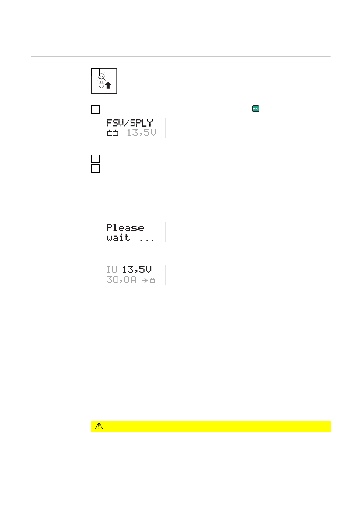
1
2
Select FSV/SPLY mode by pressing the info button
3Connect (+) charging terminal to positive pole on battery
Connect (-) charging terminal to negative pole on the battery, or to vehicle
4
body (e.g. engine block) in the case of vehicle electrical systems
Charger detects that the battery is connected, carries out a self test and
starts external power supply.
Self test
Starting the external power
supply manually
By pressing the info button, the parameters are displayed in the following
sequence:
actual charging current
-
actual battery voltage
-
amount of charge (Ah) fed in so far
-
energy (Wh) fed in so far
-
length of time charging so far
-
IMPORTANT! Start external power supply manually if:
there is no battery connected to the vehicle
-
the battery voltage on the connected battery is < 1.0 V
-
CAUTION!
Risk of serious damage as a result of incorrectly connected charging terminals.
The reverse polarity protection facility is inoperative if the external power supply
is started manually.
Connect charging terminals to correct poles and ensure proper electrical connection to vehicle terminals.
the maximum voltage command value set
-
in the USER menu is shown in the top half
of the display.
the current parameters are shown in the
-
bottom half of the display.
22
Page 23
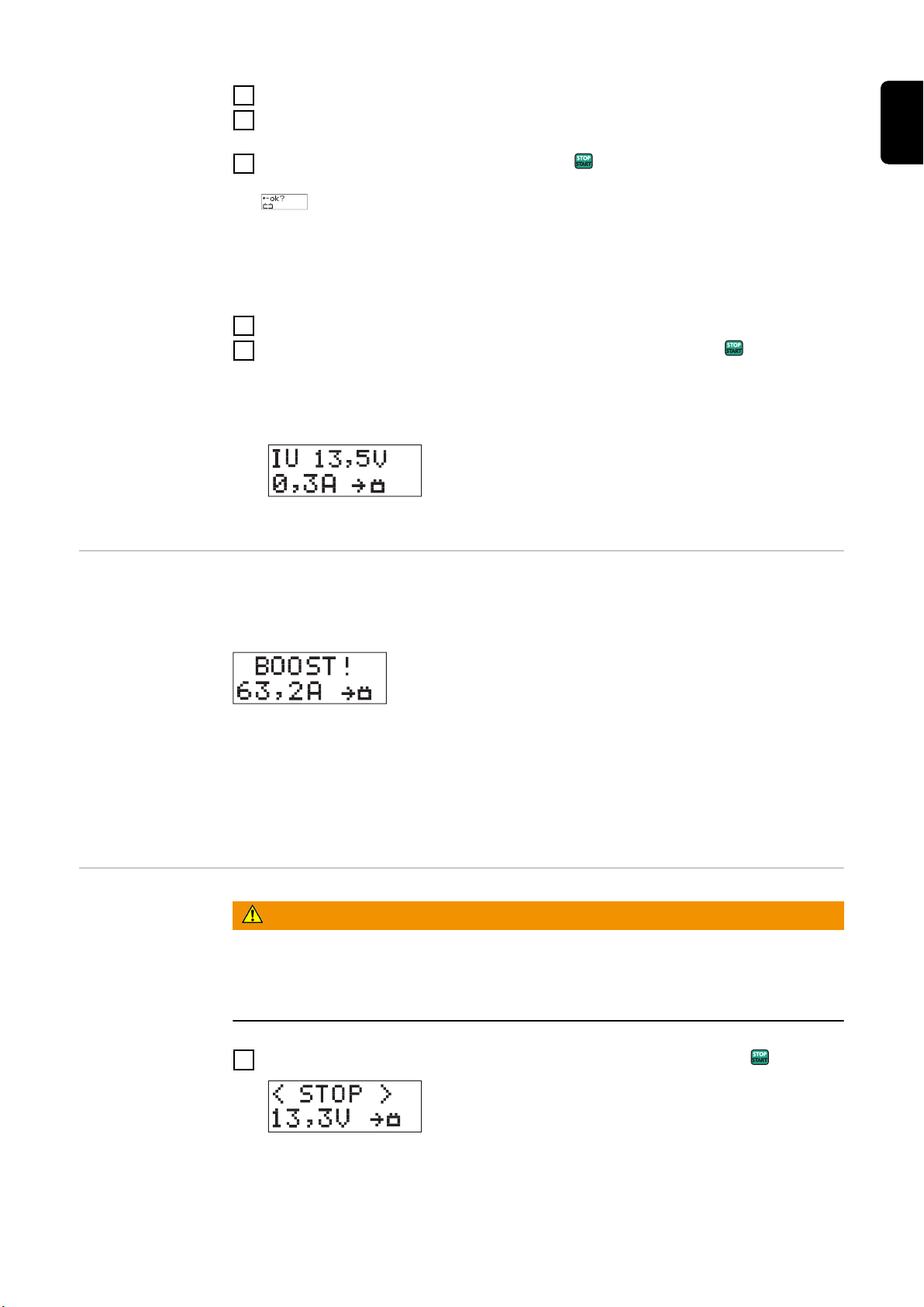
1Connect (+) charging terminal to positive pole on battery
Connect (-) charging terminal to negative pole on the battery, or to vehicle
2
body (e.g. engine block) in the case of vehicle electrical systems
3
press start/stop button for approx. 5 secs
A query regarding correct polarity of the charging terminals is displayed:
Starting the external power supply confirms the correct polarity connection. If the external power supply is not started within 2.5 secs, the device
reverts to menu mode.
Ensure charging terminals are connected to correct poles
4
5
Start external power supply by pressing the start/stop button
The charger starts the external power supply.
EN
Boost mode If the battery voltage drops while power is being supplied externally because
more power is needed (e.g. because additional consumer loads are switched on),
the device goes into boost mode.
IMPORTANT! To maintain the battery voltage at a constant level, the charger
can increase the current in boost mode to the maximum charging current (see
Technical Data).
To prevent the device overheating, the max. output current can be automatically
limited if the ambient temperature is high (power derating).
Stopping the external power
supply and dis-
Risk of explosion due to sparkinhg when disconnecting the charging terminals.
WARNING!
connecting the
charging terminals
Before disconnecting the charging terminals, stop external power supply by
pressing the start/stop button and possibly provide adequate ventilation.
1
Stop the external power supply by pressing the start/stop button
23
Page 24

By pressing the info button, the parameters are displayed in the following
sequence:
actual charging current
-
actual battery voltage
-
amount of charge (Ah) fed in so far
-
energy (Wh) fed in so far
-
length of time charging so far
-
2Disconnect (-) charging terminal from battery
Disconnect (+) charging terminal from battery
3
4
24
Page 25

Charge acceptance test
General Charge acceptance test mode is used to determine a battery’s ability to accept a
charge.
The charge acceptance test takes place as follows:
charge acceptance testing is conducted automatically for a period of 15
-
minutes; if the result is positive, the device will then switch automatically to
standard charging mode and charge the battery
if the result is negative, „Test Fail“ appears on the charger’s screen and char-
-
ging of the battery is halted
A prerequisite for a satisfactory charge acceptance test is compliance with EU
standard EN-50342-1:2006 item 5.4 (battery approx. 50% discharged).
Preparations To ensure the battery is about 50% discharged, the following preparations can be
carried out immediately before the charge acceptance test:
Fully charge the battery
1
Calculate the discharge current:
2
EN
Start the charge
acceptance test
battery capacity (Ah)
discharge current =
Charge battery for approx. 5 hours with the calculated discharge current
3
1
2
Select the charge acceptance test mode by pressing the info button
10
Set the capacity of the battery to be tested using the „up“ and „down“ but-
3
tons
4Connect (+) charging terminal to positive pole on battery
(Connect (-) charging terminal to negative pole on the battery, or to vehicle
5
body (e.g. engine block) in the case of vehicle electrical systems
25
Page 26

Charger detects that the battery is connected, carries out a self-test and
starts the charge acceptance test.
Starting the
charge acceptance test manually
Self test
Charge acceptance
test
CAUTION!
Risk of serious damage if the charging terminals are connected incorrectly.
The reverse polarity protection facility is inoperative if the current input test is
started manually (battery voltage < 1.5 V).
Connect charging terminals to correct poles and ensure proper electrical connection to vehicle terminals.
1Connect (+) charging terminal to positive pole on battery
Connect (-) charging terminal to negative pole on the battery, or to vehicle
2
body (e.g. engine block) in the case of vehicle electrical systems.
3
Press start/stop button for approx. 5 secs
A query regarding correct polarity of the charging terminals is displayed:
Retrieving parameters during
the charge acceptance test
Charge acceptance test finished - battery
OK
Starting the charge acceptance test confirms the correct polarity connection. If thecharge acceptance test is not started within 2.5 secs, the device
reverts to menu mode.
Ensure charging terminals are connected to correct poles
4
5
Start the charge acceptance test by pressing the start/stop button
The charger starts the charge acceptance test.
By pressing the info button, the parameters are displayed in the following sequence:
actual battery current
-
actual battery voltage
-
amount of charge (Ah) fed in so far
-
energy (Wh) fed in so far
-
time that has elapsed since the start of the test
-
The battery is OK, when the charger will switch automatically to standard charging mode and charge the battery after the charge acceptance test has been carried out.
By pressing the Info button stored test parameters and the actual charging parameters can be viewed:
26
Page 27

the top half of the display features progress bars to
-
show the progress of the current charging operation
E.g.: actual charging current
the bottom half of the display shows the current
-
charging parameters / calculated test parameters
By repeated pressing the info button, the other parameters are displayed in the
following sequence:
Charging parameters:
E.g.: actual battery voltage E.g.: amount of charge fed in E.g.: energy fed in
E.g.: length of time charging so
far
EN
Charge acceptance test finished - battery
faulty
Test parameters: can be identified by the test symbol
E.g.: charging current E.g.: battery voltage E.g.: set battery capacity
E.g.: Battery’s capacity to accept charge, expressed in %
IMPORTANT! A fully-charged battery can also return a negative test result. In
this case the battery must be discharged (see chapter entitled Charge acceptance test - Preparations).
The charge acceptance test shows that the battery is faulty. The battery receives
no further charge. The result is displayed on the screen:
the top half of the display shows „Test Fail“ at a
-
negative result of the charge acceptance test
the bottom half of the display shows the calculated
-
E.g.: charging current
para-meters
By pressing the Info button the following parameters can be to retrieved:
27
Page 28

E.g.: battery voltage E.g.: set battery capacity E.g.: Battery’s capacity to ac-
cept charge, expressed in %
If the terminals are disconnected from the battery in this mode, the charger reverts to the Operating Mode menu.
28
Page 29

Setup menu
General remarks The setup menu gives you the ability to configure the device’s basic settings ac-
cording to your own requirements. You can also store frequently used charge settings.
WARNING!
Operating the equipment incorrectly can cause serious damage.
The functions described must only be carried out by trained and qualified personnel. In addition to the safety rules in these operating instructions, the safety
rules of the battery and vehicle manufacturers must also be followed.
EN
Setup menu overview
USER U/I
Setting of following parameters:
maximum charging current (standard charging)
-
main charging voltage (standard charging)
-
conservation charging voltage (standard char-
-
ging)
safety cut-out (standard charging)
-
maximum charging current (user charging)
-
main charging voltage (user charging)
-
conservation charging voltage (user charging)
-
safety cut-out (user charging)
-
maximum external power supply
-
external power supply voltage
-
refresh charging voltage
-
refresh charging period
-
exit USER U/I menu
-
PREFERRED SETTINGS
Saves the frequently used operating modes you
wish to keep once the charger leads are removed
or the charger is disconnected from the mains
CHARGING CABLE
Settings defining the length and cross-section of
the charging cable
FACTORY SETTING
Resets device to factory setting
DELAY TIME
Sets the charging start delay time. Charging starts
after a predefined period.
DEVICE VERSION
For querying the current hardware and firmware
version
DEVICE HISTORY
Checking operating hours counter
29
Page 30

EXIT SETUP
Exits the setup menu
Accessing setup
menu
Setting parametes in the
USER U/I menu
1
To access menu: press info button for approx. 5 secs
2
Select menu item using the „up“ and „down“ buttons
3
Enter the selected menu item by pressing the start/stop button
IMPORTANT! If no selection is made within 30 seconds, the setup menu is exited
automatically.
1
The screen to enter the access code is displayed:
Enter access code 3831:
Using the „up“ and „down“ buttons, enter the correct digit in the underlined
2
position
3
Press the info button to go to the next position
Repeat steps 2 and 3 until all four digits have been entered correctly
4
5
Press the start/stop button to confirm the access code is correct
The first parameter in the USER U/I menu is displayed.
Setting parameter - general:
6
Select the desired parameter using the „up“ and „down“ buttons
30
7
Press the start/stop button
Page 31

Display flashes.
Adjust the desired value of the selected parameter using the „up“ and
8
„down“ buttons
9
Press the start/stop button to save the value
Parameters in the USER U/I menu
maximum charging current (standard charging)
Setting range: see Technical Data, in steps of 0,5 A
main charging voltage (standard charging)
setting range: 12.0 - 15.5 V, in steps of 0.1 V
EN
conservation charging voltage (standard charging)
setting range: Off / 12.0 - 15.5 V, in steps of 0.1 V
IMPORTANT! the conservation charging voltage is only available in Charge
mode. Conservation charging does not take place if conservation charging is
set to OFF. However, if the battery voltage drops below 12 V, charging starts
safety cut-out (standard charging)
setting range: 2 h - 30 h, in 10 min intervals
IMPORTANT! If charging does not end automatically after the set time has
elapsed, the charger will be switched off as a safety precaution.
maximum charging current (user charging)
Setting range: see Technical Data, in steps of 0.5 A
31
Page 32

main charging voltage (user charging)
setting range: 12.0 - 15.5 V, in steps of 0.1 V
conservation charging voltage (user charging)
setting range: Off / 12.0 - 15.5 V, in steps of 0.1 V
IMPORTANT! Conservation charging does not take place if conservation charging is set to OFF. However, if the battery voltage drops below 12 V, charging
starts.
safety cut-out (user charging)
setting range: 2 h - 30 h, in 10 min intervals
IMPORTANT! If charging does not end automatically after the set time has
elapsed, the charger will be switched off as a safety precaution..
maximum external power supply
Setting range: see Technical Data, in steps of 0.5 A
external power supply voltage
setting range: 12.0 - 15.5 V, in steps of 0.1 V
refresh charging voltage
setting range: 12.0 - 17.0 V, in steps of 0.1 V
32
refresh charging period
setting range: 2 h - 30 h, in 10 min intervals
Page 33

to exit the USER U/I menu
EN
PRESET menu settining preferred operating
modes
IMPORTANT! To avoid damage to the vehicle electronics, the refresh charging
mode cannot be saved.
1
Select one of the following operating modes using the „up“ and „down“ but-
2
tons
Preferred Setting Used Mode (factory setting)
After disconnecting the charging terminals or
mains supply, the last mode selected is saved.
Preferred Setting: charge acceptance test mode
After disconnecting the charging terminals or
mains supply, the charge acceptance test mode is
saved.
Preferred Setting: standard charging mode
After disconnecting the charging terminals or
mains supply, the standard charging mode is saved.
Preferred Setting: user charging mode
After disconnecting the charging terminals or
mains supply, the user charging mode is saved.
Preferred Setting: external power supply mode
After disconnecting the charging terminals or
mains supply, the external power supply mode is
saved.
3
Save the desired mode by pressing the start/stop button
IMPORTANT! Regardless of the „preferred setting“ saved, another mode can be
selected at any time. After disconnecting the charging terminals or mains supply,
the device automatically reverts to the saved „preferred setting“.
33
Page 34

CHARGING
CABLE menu setting charging
cable data
1
The length of the charger cable is displayed.
If necessary, change measure (metric/imperial) by pressing the info button
2
3
To adjust the length of the charger cable press the start/stop button
The length of the charger cable flashes.
Set the length of the charger cable using the „up“ and „down“ buttons
4
Setting range: 1 to 25 m (3 ft. 3 in. to 82 ft.)
5
To save the length of the charger cable press the start/stop button
Select the cross-section of the charger cable using the „up“ and „down“ but-
6
tons
To adjust the cross-section of the charger cable press the start/stop button
7
The cross-section of the charger cable flashes.
34
Set the the cross-section of the charger cable using the „up“ and
8
„down“ buttons
Setting range: 4 - 6 - 10 - 16 - 25 - 35 - 50 mm² (AWG 10 bis AWG 1)
9
To save the cross-section of the charger cable press the start/stop button
10
Select EXIT CH. CABLE using the „up“ und „down“ buttons
Page 35

FACTORY SETTING menu - Reset device to
factory setting
11
Press Start/Stop button to exit
1
„Device resetted“ appears for 1 second.
Device has been reset to factory setting. The submenu is exited automatically.
EN
DELAY TIME
menu - setting
the delay time
1
The delay time flashes.
Set the desired delay time using the „up“ and „down“ buttons
2
Setting range: 0 - 4 h
3
To save the delay time press the start/stop button
IMPORTANT! Delay time must be set again after each cycle. If the power fails,
the countdown stops. Once the power is restored, the countdown continues
where it left off.
35
Page 36

DEVICE VERSION menu viewing device
data
1
2
Select one of the following views using the „up“ and „down“ buttons
DEVICE HISTORY menu querying operating hours
Firmware
Displays the firmware version
Boot programm
Displays the boot program version
Hardware
Displays the hardware version installed on the
device
Exit
Press start/stop button to exit the DEVICE VERSION menu
1
2
Select one of the following views using the „up“ and „down“ buttons
Operating Hours
Shows the operating hours (device connected to
the mains or switched on)
Charging Hours
Displays the operating time (time during which the
device has been producing power)
Cumulated Ampere Hours
Displays the amount of charge produced
Exit
Press the start/stop button to exit the DEVICE
HISTORY menu
36
Page 37

Troubleshooting
EN
Troubleshooting
Charging terminals connected to wrong poles
Cause Charging terminals connected to wrong poles
Remedy Swap charging terminals round
Charging terminals short-circuited
Cause Short-circuit on the charging terminals
Remedy Rectify short-circuit on the charging terminals
Cause Battery not detected
Remedy Check that charging terminals are properly connected,
press Start/Stop button for 5 seconds
Over-temperature
Cause Over-temperature - charger too hot
Remedy Allow charger to cool down
Cause Air inlets and outlets covered
Remedy Ensure air inlets and outlets are not obstructed
Safety cut-out
Cause Battery faulty
Remedy Check battery
Cause Charger incorrectly set
Remedy Check settings: Ah, voltage
Cause Incorrect battery type (e.g. NiCd), incorrect number of
cells (voltage)
Remedy Check battery type
Fan blocked/faulty
37
Page 38

Cause Fan blocked
Remedy Check air inlet, remove foreign bodies if necessary
Cause Fan faulty
Remedy Contact specialist dealer
Fuse faulty
Cause Secondary fuse faulty
Remedy Contact specialist dealer
Charger faulty
Cause Charger faulty
Remedy Contact specialist dealer
Nothing on display
Cause Mains supply interrupted
Remedy Connect mains supply
Cause Mains plug or mains cable faulty
Remedy Replace mains plug or mains cable
Cause Charger faulty
Remedy Contact specialist dealer
Charger does not start charging
Cause Charging terminals or charger lead faulty
Remedy Replace charging terminals or charger lead
(M8 nut torque = 15 Nm)
38
Page 39

Symbols used
EN
Warning notices
affixed to the
charger
Follow operating instructions
Connect battery poles correctly:
(+) red (-) black
Detonating gas is generated in the battery during charging.
Risk of explosion!
The charger heats up depending on operating conditions.
Before disconnecting the charger lead from the battery, interrupt
charging.
Chargers may only be opened by a qualified electrician
Avoid flames and sparks during charging.
Ensure adequate ventilation during charging.
Battery acid is corrosive.
For indoor use only.
Do not expose to rain.
39
Page 40

Technical data
Acctiva Professional Flash,
Acctiva Professional Flash
AUS, Acctiva
Professional
Flash JP,
Acctiva Professional 30A JP
Mains voltage (+/- 15%)
Acctiva Professional Flash
Acctiva Professional Flash AUS
Acctiva Professional Flash JP
Acctiva Professional 30A JP
Nominal output max.
Acctiva Professional Flash
Acctiva Professional Flash AUS
Acctiva Professional Flash JP
Acctiva Professional 30A JP
Charging voltage 12,0 - 15,5 V
Charging current I2 (adjustable)
Acctiva Professional Flash
Acctiva Professional Flash AUS
Acctiva Professional Flash JP
Acctiva Professional 30A JP
Boost mode charging current
t
(tI
2 max
Acctiva Professional Flash
Acctiva Professional Flash AUS
Acctiva Professional Flash JP
Acctiva Professional 30A JP
= 30 s, tI2 = 60 s)
2 max
230 V AC, 50/60 Hz
240 V AC, 50/60 Hz
100 V AC, 50/60 Hz
100 V AC, 50/60 Hz
1080 W
1080 W
1080 W
710 W
2 - 50 A
2 - 50 A
2 - 50 A
2 - 30 A
max. 70 A
max. 70 A
max. 70 A
max. 30 A
Nominal charging capacity 10 - 250/300 Ah
Number of cells 6
Charging characteristic IUoU / IUa / IU
Operating temperature * 0 °C to +60 °C
32 °F to 140 °F
Storage temperature -20 °C to +80 °C
4 °F to 176 °F
Interface USB
EMC Class
Acctiva Professional Flash
Acctiva Professional Flash AUS
Acctiva Professional Flash JP
Acctiva Professional 30A JP
Protection IP 20
Marks of conformity see charger rating plate
Weight inclusive of mains and charger leads
Dimensions w x h x d 315 x 200 x 110 mm
IEC/EN 61000-6-4/2 (EMC class A)
IEC/EN 61000-6-4/2 (EMC class A)
IEC/EN 61000-6-4 (EMC class A)
J 55014
6,5 kg
14.33 lb.
12.40 x 7.87 x 4.33 in.
40
* If the ambient temperature rises to above 35°C (95°F) or thereabouts
(depending on secondary voltage), the secondary output current is reduced (power derating)
Page 41

EN
41
Page 42

42
Page 43

EN
43
Page 44
 Loading...