

Page 1

/ Battery Charging Systems / Welding Technology / Solar Electronics
Abspul VR
Unreeling device VR
Dévidoir VR
Einbauanleitung
MIG/MAG Systemerweiterung
DEENFR
Installation Instructions
MIG/MAG system extension
Instructions d‘installation
Extension système MIG/MAG
42,0410,1464 002-27032012
Page 2

Page 3

Allgemeines
WARNUNG! Ein elektrischer Schlag kann tödlich sein. Vor dem Öffnen des
Gerätes:
- Netzschalter der Stromquelle in Stellung - O - schalten
- Stromquelle vom Netz trennen
- Deutlich lesbares und verständliches Warnschild gegen Wiedereinschalten
anbringen
Nach dem Öffnen des Gerätes gegebenenfalls spannungsführende Bauteile
(z.B. Kondensatoren) entladen.
DE
Sicherheit
Lieferumfang
WARNUNG! Fehlerhaft durchgeführte Arbeiten können schwerwiegende Sach-
und Personenschäden verursachen. Diese Montage darf nur von geschultem
Fachpersonal durchgeführt werden! Beachten Sie die Sicherheitsvorschriften in
der Bedienungsanleitung der Stromquelle.
(1)
(9)
Abb.1 Lieferumfang
(1) Kabelbinder
(2) Fächerscheibe M5
(3) Mutter M5
(4) 2x Schrauben 3 x 12
(5) 2x Schrauben 3,5 x 9,5
(6) 2x Fächerscheibe M3
(7) 2x Mutter M3
(8) Etikett VR 1530
(9) Kabelbaum Abspul VR und 17 poliger-Anschlussstecker
(2)
(3)
(4)
(5)
(6)
(7)
(8)
Hinweis zum
Anschlussstecker
Wichtig! Der Anschlussstecker muss angeschlossen werden, wenn kein Abspul VR an
der Stromquelle angeschlossen ist.
1
Page 4

Einbauset Abspul VR montieren
Vorbereitung 1. Rechtes Seitenteil demontieren
Abb.2 Stromquelle geöffnet
2. Kabelbinder im Bereich der Option VR
Control intern durchtrennen
Abb.3 Kabelbinder durchtrennen
(1)
Abb.4 Erdverbindung lösen
3. Leitung mit Kabelschuh (1) von der
Metalldistanz demontieren
2
Page 5

Vorbereitung
(Fortsetzung)
4. Eine Blindabdeckung (2) entfernen
DE
(2)
Abb.5 Blindabdeckung entfernen
Einbauset Push
Pull-Unit montieren
Abb.6 Print PM 41 aufsetzen
(3)
1. Print PM 41 auf die Distanzen aufsetzen (Einbauanleitung Push Pull-Unit
beachten
2. Print PM 41 mit zwei Kunststoffdistan-
(3)
zen (3) befestigen
3. Leitung mit Kabelschuh an der Metalldistanz (4) mit Fächerscheibe und M5
Mutter befestigen
(4)
Abb.7 PM41 montieren und anschließen
3
Page 6
Einbauset Abspul
VR montieren
(Fortsetzung)
(5)
(5)
(5)
Abb.8 Stecker vom Kabelbaum anstecken
4. Schrauben von der Rückfront (5) lösen
(5)
5. Rückfront (6) nach vorne klappen
6. Anschlussbuchse (7) des Kabelbaum
vom E-Set durch den freien Optionsplatz stecken
7. Kabelbaum mit 2 Schrauben 3,5 x 9,5
montieren
(7)
Abb.9 Erdverbindung herstellen
(6)
(8)
Abb.10 Kabelbinder durchtrennen
HINWEIS! Für ausreichende
Erdung sorgen. Die Leitung mit
Kabelschuh muss fest an der
Schraube montiert sein, sodass
eine gute Erdverbindung zwischen
Anschlussbuchse und Rückseite
der Stromquelle besteht.
8. Leitung mit Kabelschuh des Kabelbaums Abspul VR mit Fächerscheibe
und Mutter an der Schraube (8) der
Rückfront montieren
9. Rückfront wieder montieren
4
Page 7

Print PM 41
verkabeln
(10)
Abb.11 Verbindung zum UST-Print
(9)
1. 14-poligen Molexstecker vom Print
SR41 / X4 abstecken
2. 14-poligen Molexstecker vom Kabelbaum Abspul VR am Print SR41 / X4
anstecken
3. Den zuvor abgesteckten 14-poligen
Molexstecker (9) am Zwischenstecker
(10) des Kabelbaums anstecken
4. 2-poligen Molexstecker des Kabelbaums am Print PM 41 / X1 anstecken
5. 4-poligen Molexstecker vom Print
SR41 / X11 abstecken und am Print
PM 41 / X2 anstecken
7. 4-poligen Molexstecker vom E-Set
Push Pull - Unit am Print SR 41 / X11
anstecken
8. Das andere Ende des 4-poligen
Molexsteckers am Print PM 41 / X3
anstecken
DE
Abschließende
Tätigkeiten
(X1)
(X2) (X3)
Abb.12 Stecker an X6 anstecken
Abb.13 Kabelbaum fixieren
Wichtig! Beim Verlegen des Kabelbaums
auf größtmöglichen Abstand zur Zwischenkreisklemme achten.
1. Kabelbaum mit Kabelbindern fixieren
2. Rechtes Seitenteil montieren
3. Aufkleber neben Anschlussbuchse
ankleben
5
Page 8

6
Page 9
General
WARNING! An electric shock can be fatal. Before opening the machine:
- Turn the power source mains switch to the „O“ position
- Unplug the power source from the mains
- Attach a clearly legible and easy-to-understand warning sign to prevent
anyone switching it on again
After opening the device, discharge any electrically charged components (e.g.
capacitors).
Safety
Scope of supply
WARNING! Work performed incorrectly can cause serious injury and damage.
This installation must only be carried out by trained and qualified personnel.
Observe the safety rules in the power source operating instructions.
(9)
EN
(1)
(2)
(3)
(4)
(5)
Notes on the
connector plug
(6)
(7)
(8)
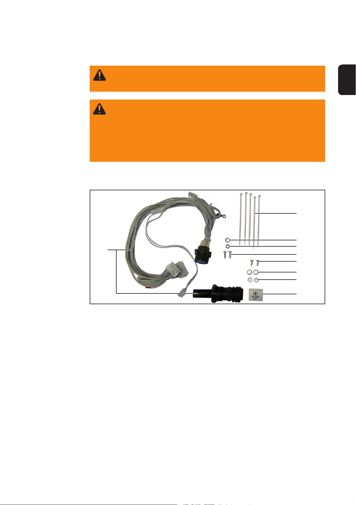
Fig. 1 Scope of supply
(1) Cable ties
(2) M5 serrated washer
(3) M5 nut
(4) Two 3 x 12 screws
(5) Two 3.5 x 9.5 screws
(6) Two M3 serrated washers
(7) Two M3 nuts
(8) VR 1530 label
(9) Cable harness unreeling device and 17-pin connector plug
Important! The connector plug must be connected when there is no unreeling device
connected to the power source.
1
Page 10

Fitting the unreeling device installation set
Preparations 1. Remove the right side panel
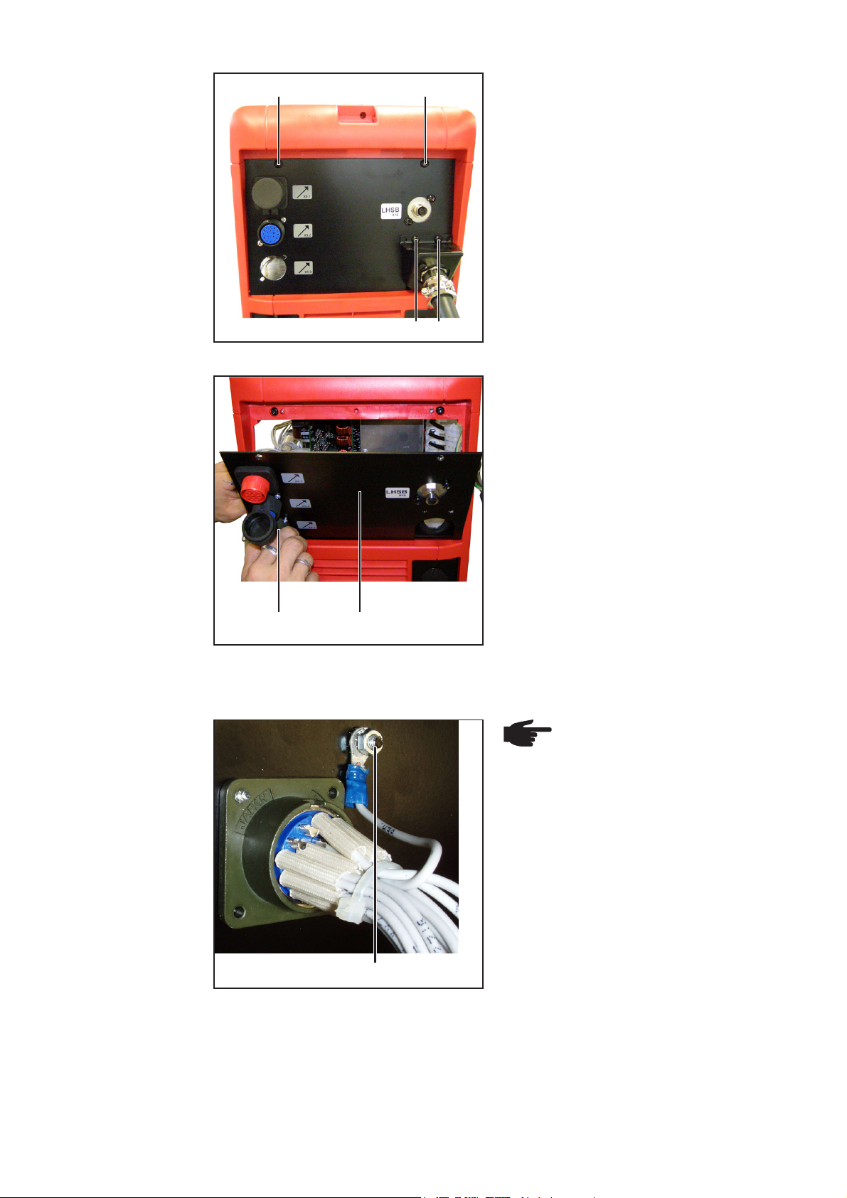
Fig. 2 Opened power source
2. Cut through the cable tie near to the
optional internal control device
Fig. 3 Cutting through the cable tie
(1)
Fig. 4 Disconnecting the earth connection
3. Remove cable with cable lug (1) from
the metal spacer
2
Page 11

Preparations
(continued)
4. Remove one blanking cover (2)
EN
(2)
Fig. 5 Removing the blanking cover
Fitting the pushpull unit installation set
Fig. 6 Positioning the PM 41 board
(3)
1. Place PM 41 board on the spacers
(observe the installation instructions
for the push-pull unit)
2. Secure the PM 41 board using two
(3)
plastic spacers (3)
3. Fasten the cable with cable lug (4) to
the metal spacer using serrated
washer and M5 nut
Fig. 7 Fitting and connecting the PM41
(4)
3
Page 12

Fitting the unreeling device
installation set
(continued)
(5)
(5)
(5)
Fig. 8 Plugging in the cable harness plug
4. Remove the screws from the back
panel (5)
(5)
5. Fold the back panel (6) forwards
6. Insert the connection socket (7) of the
cable harness from the installation set
into the free option slot
7. Fit the cable harness using two 3.5 x
9.5 screws
(7)
Fig. 9 Establishing the earth connection
(6)
(8)
Fig. 10 Cutting through the cable tie
NOTE! Ensure adequate earthing.
The cable with cable lug must be
securely attached to the screw so
that there is a good earth connection between the connection
socket and the back panel of the
power source.
8. Attach the cable with cable lug from
the unreeling device cable harness to
the screw (8) on the back panel using
the serrated washer and nut
9. Refit the back panel
4
Page 13

Wiring up the PM
41 board
(10)
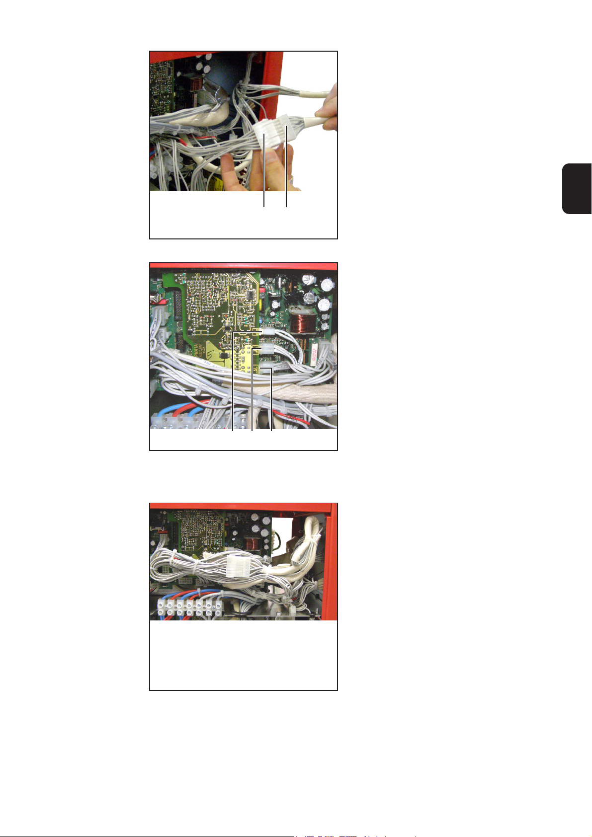
Fig. 11 Connection to the UST board
(9)
1. Unplug the 14-pin Molex plug from
SR41 board /X4
2. Connect the 14-pin Molex plug unreeling device cable harness to SR41
board /X4
3. Plug the previously unplugged 14-pin
Molex plug (9) into the cable harness
adapter (10)
4. Plug the 2-pin cable harness Molex
plug into PM 41 board /X1
5. Unplug the 4-pin Molex plug from
SR41 board /X11 and plug into PM 41
board /X2
7. Plug the 4-pin Molex plug from the
push-pull-unit installation set into SR
41 board /X11
8. Plug the other end of the 4-pin Molex
plug into PM 41 board /X3
EN
Finally...
(X1)
(X2) (X3)
Fig. 12 Plugging the plug into X6
Fig. 13 Securing the cable harness
Important! When routing the cable harness, ensure the greatest possible distance from the intermediate circuit terminal.
1. Secure cable harness with cable ties
2. Fit the right side panel
3. Stick the label near to the connection
socket
5
Page 14

6
Page 15

Généralités
AVERTISSEMENT ! Une décharge électrique peut être mortelle. Avant d’ouvrir
l’appareil :
- Placer l’interrupteur principal de la source de courant en position - O -
- Débrancher la prise secteur de la source de courant
- Placer un écriteau parfaitement lisible et compréhensible sur l’appareil
pour que personne ne le rallume
Après ouverture de l’appareil, le cas échéant, décharger les éléments conducteurs de tension (par ex. condensateurs).
Sécurité
Livraison
AVERTISSEMENT ! Les erreurs en cours d’opération peuvent entraîner des
dommages corporels et matériels graves. Ce montage doit être effectué exclusivement par du personnel qualifié et formé. Respectez les consignes de sécurité
figurant dans le mode d’emploi de la source de courant.
FR
(1)
(9)
Fig. 1 Contenu de la livraison
(1) Attache-câbles
(2) Rondelle en éventail M5
(3) Écrou M5
(4) 2x vis 3 x 12
(5) 2x vis 3,5 x 9,5
(6) 2x rondelles en éventail M3
(7) 2x écrou M3
(8) Étiquette VR 1530
(9) Faisceau de câbles dévidoir VR et prise de connexion 17 pôles
(2)
(3)
(4)
(5)
(6)
(7)
(8)
Remarque concernant la prise
de connexion
Important ! La prise de connexion doit être raccordée si aucun dévidoir VR n’est branché
sur la source de courant.
1
Page 16

Montage du kit d’installation du dévidoir VR
Préparation 1. Démonter le panneau latéral droit
Fig. 2 Source de courant ouverte
2. Sectionner l’attache-câbles à proximité de l’option VR Control interne
Fig. 3 Sectionner l’attache-câbles
(1)
Fig. 4 Débrancher la liaison à la terre
3. Démonter le câble par la cosse du
câble (1) de l’écarteur métallique
2
Page 17

Préparation
(suite)
4. Retirer une fausse prise (2)
FR
(2)
Fig. 5 Retirer une fausse prise
Montage du kit
d’installation de
l’unité Push-Pull
Fig. 6 Mettre en place le circuit imprimé PM 41
(3)
1. Placer le circuit imprimé PM 41 sur
les écarteurs (respecter le mode
d’emploi de l’unité Push Pull)
2. Fixer le circuit imprimé PM 41 avec
(3)
deux écarteurs en plastique (3)
3. Fixer le câble par la cosse du câble
(4) sur l’écarteur métallique avec la
rondelle en éventail et l’écrou M5
(4)
Fig. 7 Monter et raccorder le circuit imprimé PM41
3
Page 18

Montage du kit
d’installation du
dévidoir VR
(suite)
(5)
(5)
(5)
(5)
Fig. 8 Brancher les fiches du faisceau de câbles
4. Retirer les vis de la face arrière (5)
5. Rabattre la face arrière (6) vers l’avant
6. Brancher le connecteur (7) du faisceau
de câbles du kit d’installation dans
l’espace disponible
7. Monter le faisceau de câbles avec 2
vis 3,5 x 9,5
(7)
Fig. 9 Assurer la liaison à la terre
(6)
(8)
Fig. 10 Sectionner l’attache-câbles
REMARQUE ! Assurer une mise à
la terre suffisante. Le câble doit
être fermement monté avec la vis
au niveau de sa cosse, de telle
sorte qu’une bonne mise à la terre
soit assurée entre le connecteur
et la face arrière de la source de
courant.
8. Monter le câble avec la cosse du
faisceau de câbles du dévidoir VR,
avec la rondelle en éventail et l’écrou,
sur la vis (8) de la face arrière
9. Remettre en place la face arrière
4
Page 19
Réalisation du
câblage du
circuit imprimé
PM41
(10)
(9)
Fig. 11 Liaison au circuit imprimé UST
1. Débrancher la fiche Molex 14 pôles du
circuit imprimé SR41 / X4
2. Brancher la fiche Molex 14 pôles du
faisceau de câbles du dévidoir VR sur
le circuit imprimé SR41 / X4
3. Brancher la fiche Molex 14 pôles
précédemment débranchée (9) sur le
connecteur intermédiaire (10) du
faisceau de câbles
FR
4. Brancher la fiche Molex 2 pôles du
faisceau de câbles sur le circuit
imprimé PM 41 / X1
5. Débrancher la fiche Molex 4 pôles du
circuit imprimé SR41 / X11 et la
brancher sur le circuit imprimé PM 41
/ X2
7. Brancher la fiche Molex 4 pôles du kit
d’installation de l’unité Push Pull sur
le circuit imprimé PM 41 / X11
8. Brancher l’autre extrémité de la fiche
Molex 4 pôles sur le circuit imprimé
PM 41 / X3
Étapes finales
(X1)
(X2) (X3)
Fig. 12 Brancher la fiche sur le X6
Fig. 13 Fixer les faisceaux de câble
Important ! Lors de la pose du faisceau de
câbles, veiller à conserver une distance
maximale par rapport à la borne du circuit
intermédiaire.
1. Fixer les faisceaux de câble avec les
attache-câbles
2. Monter le panneau latéral droit
3. Coller l’étiquette à côté du connecteur
5
Page 20

FRONIUS INTERNATIONAL GMBH
Froniusplatz 1, A-4600 Wels, Austria
Tel: +43 (0)7242 241-0, Fax: +43 (0)7242 241-3940
E-Mail: sales@fronius.com
www.fronius.com
Under http://www.fronius.com/addresses you will find all addresses
www.fronius.com/addresses
of our Sales & service partners and Locations.
ud_fr_st_so_00082 012011
 Loading...