

Page 1

Operating
Instructions
AB Interbus FSMA
Bedienungsanleitung
DE
Operating Instructions
EN
Instructions de service
FR
42,0410,1373 004-15022023
Page 2

Page 3

Inhaltsverzeichnis
Allgemeines 4
Sicherheit 4
Grundlagen 4
Gerätekonzept 4
Anschlüsse am Interface 5
Zusatzhinweise 5
Anwendungsbeispiel 5
AB Interbus FSMA anschließen und konfigurieren 6
Allgemeines 6
Sicherheit 6
Anschlüsse, Einstellmöglichkeiten und Anzeigen am Anybus-S Interbus Fibre Optic Busmodul
Interface AB Interbus FSMA anschließen 7
Geschwindigkeit der Datenübertragung (Baudrate) einstellen 7
Fehlerdiagnose, Fehlerbehebung 8
Betriebszustand LEDs am Print UBST 1 8
LED „+5 V“ (1) 8
LEDs „Traffic 1 - 4“ (2) 8
LEDs „L1 - L7“ (3) 9
LED „EXT“ (4) 9
Jumper „EXT“ (5) / Jumper „INT“ (6) 9
LED „INT“ (7) 10
LED „VCC“ (8) 10
LED-Anzeige am Anybus-S Interbus Fibre Optic Busmodul 10
Statusanzeige Anybus-S 11
Eigenschaften der Datenübertragung und technische Daten 12
Eigenschaften der Datenübertragung 12
Sicherheitseinrichtung 12
Technische Daten AB Device-Net Enterprise 12
Signalbeschreibung AB Interbus FSMA 13
Allgemeines 13
Betriebsarten der Stromquelle 13
Übersicht 13
Ein- und Ausgangssignale für MIG/MAG 14
Eingangssignale (vom Roboter zur Stromquelle) 14
Ausgangssignale (von der Stromquelle zum Roboter) 15
Ein- und Ausgangssignale für WIG 17
Eingangssignale (vom Roboter zur Stromquelle) 17
Einstellung Puls-Bereich WIG 18
Ausgangssignale (von der Stromquelle zum Roboter) 18
Ein- und Ausgangssignale für CC/CV 20
Eingangssignale (vom Roboter zur Stromquelle) 20
Ausgangssignale (von der Stromquelle zum Roboter) 21
Ein- und Ausgangssignale für Standard-Manuell 23
Eingangssignale (vom Roboter zur Stromquelle) 23
Ausgangssignale (von der Stromquelle zum Roboter) 24
Schaltplan 26
DE
6
3
Page 4

Allgemeines
Sicherheit
Gefahr durch Fehlbedienung und fehlerhaft durchgeführte Arbeiten.
Schwere Personen- und Sachschäden können die Folge sein.
▶
▶
▶
Grundlagen Interbus
Das Interbus-System ist als Datenring mit einem zentralen Master / Slave Zugriffsverfahren aufgebaut. Die Verwendung der Ringstruktur ermöglicht das zeitgleiche Senden und Empfangen von Daten. Die beiden Datenrichtungen des Ringes sind in einem Kabel untergebracht. Jeder Teilnehmer im Interbus-System hat
ein ID-Register (Identifikationsregister). In diesem Register sind Informationen
über den Modultyp, die Anzahl der Ein- und Ausgangsregister sowie Status- und
Fehlerzustände enthalten.
Interbus ist sowohl für schnelle, zeitkritische Datenübertragungen als auch für
umfangreiche und komplexe Kommunikationsaufgaben geeignet.
Anybus-S Interbus Fibre Optic Busmodul
Das Anybus-S Interbus Fibre Optic Busmodul ist ein vollständiger Interbus-S
Slave. Es enthält alle analogen, digitalen und optischen Komponenten einer leistungsfähigen Interbus-Anbindung für die Übertragung mittels Lichtwellen-Leiter.
Ein eingebauter Mikroprozessor wickelt den gesamten Busverkehr automatisch
ab.
WARNUNG!
Alle in diesem Dokument beschriebenen Arbeiten und Funktionen dürfen
nur von technisch geschultem Fachpersonal ausgeführt werden.
Dieses Dokument vollständig lesen und verstehen.
Sämtliche Sicherheitsvorschriften und Benutzerdokumentationen dieses
Gerätes und aller Systemkomponenten lesen und verstehen.
Das Anybus-S Interbus Fibre Optic Busmodul kommt bei der Übertragung
großer Datenmengen mit hohem Datendurchsatz und höchster Zuverlässigkeit
zum Einsatz. Die Übertragung mittels Lichtwellenleiter bietet höchste Sicherheit
gegen Störeinflüsse und gewährleistet eine lange Betriebsdauer ohne Austausch
der Lichtleiter.
Das Anybus-S Interbus Fibre Optic Busmodul unterstützt maximal 10 Worte
Prozessdaten, sowie die Interbus Baudraten 500 kbit/s und 2 Mbit/s.
Die Interbus-Schnittstelle ist in geregelter Lichtwellenleiter Technologie ausgeführt und mit FSMA Anschlüssen gemäß IEC 874-2 und DIN 47258 ausgestattet.
Gerätekonzept Das Interface AB Interbus FSMA enthält einen Print UBST 1, auf dem ein Any-
bus-S Interbus Fibre Optic Busmodul aufgebaut ist. Im CFM des Print UBST 1
sind alle Informationen für eine Interbus-Anbindung gespeichert.
4
Page 5

Anschlüsse am
(2)
(1)
(3) (4)
(1) (2)
(3)
(4)
(5)
(6) (7)
(8)
(9)
(10)
Interface
Anschlüsse am Interface
(1) Zugentlastung
zum Durchführen der InterbusDatenleitung und der Spannungsversorgung
(2) LocalNet Anschluss
zum Anschließen des ZwischenSchlauchpaketes
(3) LocalNet Anschluss
zum Anschließen weiterer Systemkomponenten
(4) LocalNet Anschluss
zum Anschließen weiterer Systemkomponenten
DE
Zusatzhinweise
Anwendungsbeispiel
HINWEIS!
Solange das Roboterinterface am LocalNet angeschlossen ist, bleibt automatisch die Betriebsart „2-Takt Betrieb“ angewählt (Anzeige: Betriebsart 2-Takt
Betrieb).
Nähere Informationen zur Betriebsart „Sonder-2-Takt Betrieb für Roboterinterface“ finden sich in den Kapiteln „MIG/MAG-Schweißen“ und „Parameter Betriebsart“ der Bedienungsanleitung Stromquelle.
(1) Stromquelle (6) Robotersteuerung
(2) Kühlgerät (7) Schweißdraht-Fass
(3) AB Interbus FSMA (8) Roboter
(4) Verbindungs-Schlauchpaket (9) Schweißbrenner
(5) Datenkabel Profibus (10) Drahtvorschub
5
Page 6

AB Interbus FSMA anschließen und konfigurieren
(1)
(2)
(3)
(4)
(5)
(6)
(7)
Allgemeines Anschließen und Konfigurieren des Interface AB Interbus FSMA erfolgt am Any-
bus-S Interbus Fibre Optic Busmodul.
Sicherheit
WARNUNG!
Gefahr durch Fehlbedienung und fehlerhaft durchgeführte Arbeiten.
Schwere Personen- und Sachschäden können die Folge sein.
Alle in diesem Dokument beschriebenen Arbeiten und Funktionen dürfen
▶
nur von technisch geschultem Fachpersonal ausgeführt werden.
Dieses Dokument vollständig lesen und verstehen.
▶
Sämtliche Sicherheitsvorschriften und Benutzerdokumentationen dieses
▶
Gerätes und aller Systemkomponenten lesen und verstehen.
WARNUNG!
Gefahr durch elektrischen Strom.
Schwere Personen- und Sachschäden können die Folge sein.
Vor Beginn der Arbeiten alle beteiligten Geräte und Komponenten ausschal-
▶
ten und von Stromnetz trennen.
Alle beteiligten Geräte und Komponenten gegen Wiedereinschalten sichern.
▶
Nach dem Öffnen des Gerätes mit Hilfe eines geeigneten Messgerätes si-
▶
cherstellen, dass elektrisch geladene Bauteile (beispielsweise Kondensatoren) entladen sind.
Anschlüsse, Einstellmöglichkeiten und Anzeigen am AnybusS Interbus Fibre
Optic Busmodul
(1) Schnittstelle zum Print UBST 1 (5) Anzeige Busspannung OK
(2) LWL-Anschluss Bus IN (6) LED-Anzeige
(3) LWL-Anschluss Bus OUT (7) Statusanzeige Anybus-S
(4) Baudraten-Wahlschalter
LWL = Lichtwellen-Leiter
6
Page 7

Interface AB In-
(1)
(3)
(2)
Bus IN
Bus OUT
2 Mbit/s 500 kbit/s
terbus FSMA anschließen
LocalNet-Stecker vom Zwischen-
1
Schlauchpaket am Anschluss Local-Net (1) anschließen
Interface-Deckel (2) abmontieren
2
Eine der 5 Blindabdeckungen ent-
3
fernen
Lichtwellen-Leiter der Interbus-
4
Datenleitung durch die Öffnung
führen
Lichtwellen-Leiter gemäß An-
5
schlussbelegung der LWLAnschlüsse Bus IN und Bus OUT
des Anybus-S Interbus Fibre Optic
Busmoduls anschließen
DE
Geschwindigkeit
der Datenübertragung
(Baudrate) einstellen
Anschlussbelegung Bus IN und Bus Out
Das Anybus-S Interbus Fibre Optic Busmodul unterstützt folgende Datenübertragungs-Geschwindigkeiten (Baudraten):
2 Mbit/s
-
500 kbit/s
-
Die Einstellung der Datenübertragungs-Geschwindigkeit erfolgt am
Baudraten-Wahlschalter.
WICHTIG! Die DatenübertragungsGeschwindigkeit vor Inbetriebnahme
einstellen. Während des Betriebes die
Datenübertragungs-Geschwindigkeit
nicht verändern.
Zum Einstellen der gewünschten
1
Datenübertragungs-Geschwindigkeit den Jumper gemäß Abbildung
positionieren.
Baudraten-Wahlschalter: Position des Jumpers
7
Page 8

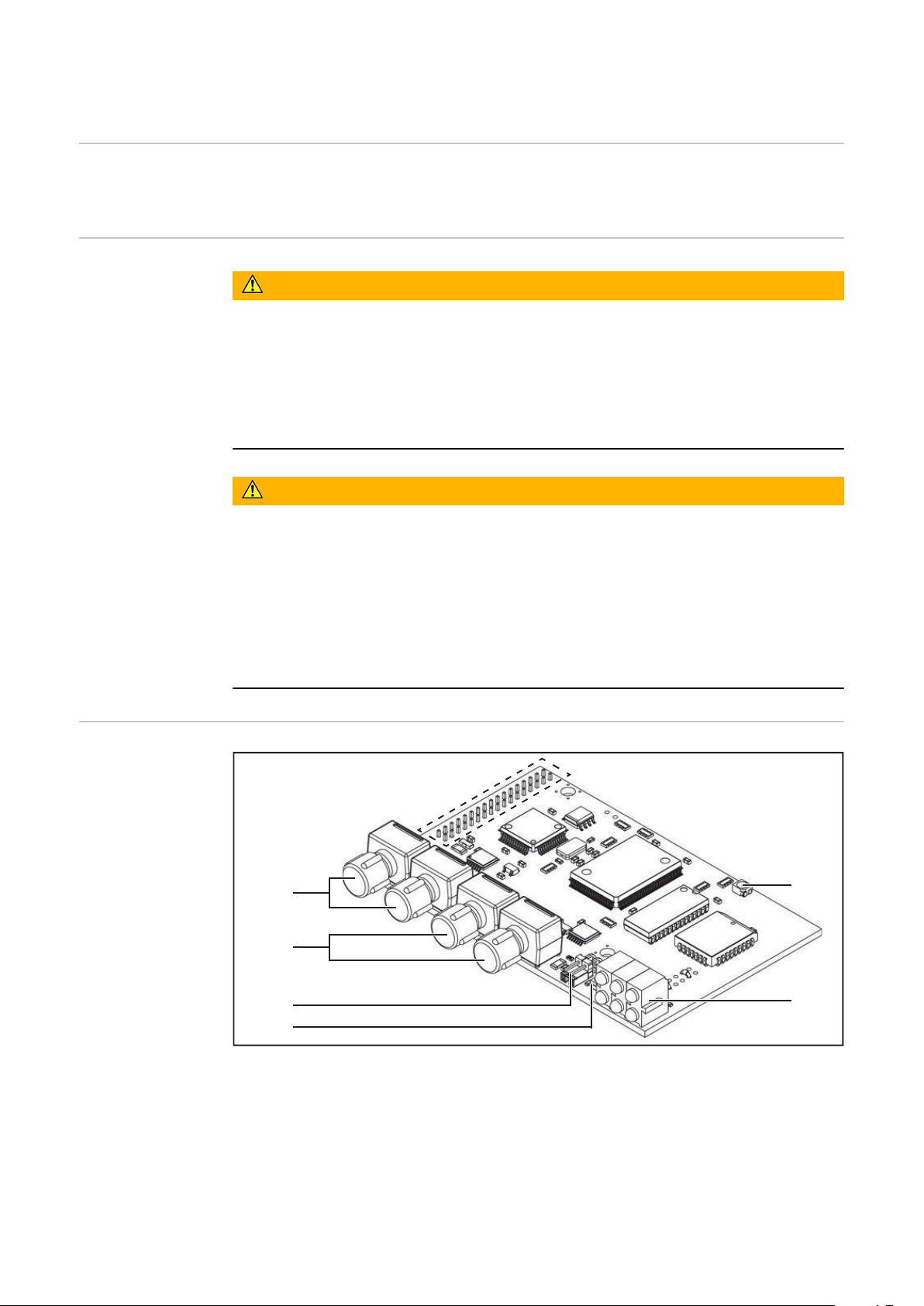
Fehlerdiagnose, Fehlerbehebung
(2)
(3)
(1)
(8)
(4)
(7)
(5)
(6)
Betriebszustand
LEDs am Print
UBST 1
(1) LED „+5 V“
(2) LEDs „Traffic 1 - 4“
(3) LEDs „L1 - L7“
(4) LED „EXT“
LED „+5 V“ (1) Die LED „+5 V“ (1) leuchtet, wenn die interne oder die externe Versorgungsspan-
LEDs „Traffic 1 4“ (2)
nung angeschlossen ist. Die LED „+5 V“ zeigt an, dass die Print-Elektronik in Ordnung ist.
LED Anzeige Bedeutung Abhilfe
Traffic X aus oder
leuchtet
Traffic X blinkt Kommunikation am Fro-
Keine Kommunikation
am Fronius LocalNet
nius LocalNet aktiv
(5) Jumper „EXT“
(6) Jumper „INT“
(7) LED „INT“
(8) LED „VCC“
Versorgungsspannung
prüfen;
Verkabelung prüfen
-
8
Page 9

LEDs „L1 - L7“
(a) (b) (c)
(3)
LED Anzeige Bedeutung Abhilfe
L1 Leuchtet /
Blinkt
Fehler im Modul aufgetreten
Siehe Fehlernummer laut
Tabelle / Servicedienst
DE
L2 Leuchtet Kommunikation am Fronius
-
LocalNet aktiv
L3 Blinkt Ethernet-Stack sendet Da-
-
ten
L6 Leuchtet Ethernet - Physikal. Verbin-
-
dung vorhanden
L7 Blinkt Ethernet-Datenübertra-
-
gung aktiv
LED „L1“ leuchtet:
Die Fehlerbeschreibung sowie die dazugehörende Display-Anzeige an der Stromquelle sind im Beiblatt ‘Roboter-Interface’ (42,0410,0616) beschrieben:
Kapitel ‘Ausgangssignale zum Roboter’, Abschnitt ‘Fehler-Nummer UBST’
LED „L1“ blinkt - Fehler wird über Blink-Code angezeigt:
(a) Schnelles Blinken:
Start des Fehlercodes
(b) Erste langsame Impulse:
Fehlerart
(c) Zweite langsame Impulse:
Fehlerstelle
Fehlercode
1 1 Max. EtherNet Framegröße über-
Fehlerargument Fehlerbeschreibung Abhilfe
Interface aus-
schritten
und einschalten
2 Falscher Mailbox-Typ -
4 UDP-Datenunterlauf auf Port 15000 -
5 UDP-Datenüberlauf -
6 UDP-Datenunterlauf auf 15001 -
7 Falscher UDP-Port -
8 Fehler bei der Stack-Initialisierung -
9 Ungültiger Funktionsaufruf -
LED „EXT“ (4) Die LED „EXT“ (4) leuchtet, wenn die externe Versorgungsspannung mittels Jum-
per „EXT“ (5) angewählt ist.
Jumper „EXT“
(5) / Jumper
„INT“ (6)
Die Jumper „EXT“ (5) und „INT“ (6) dienen zum Auswählen zwischen interner
und externer Spannungsversorgung. Im Auslieferungszustand befindet sich der
Jumper auf „externer Spannungsversorgung“.
9
Page 10

LED „INT“ (7) Die LED „INT“ (7) leuchtet, wenn die interne Versorgungsspannung mittels Jum-
(2) (3)
(4)
(1)
(5) (6)
per „INT“ (6) angewählt ist.
LED „VCC“ (8) Die LED „VCC“ (8) leuchtet, wenn die interne oder externe Versorgungsspannung
angeschlossen ist. Die LED „VCC“ zeigt an, dass die Spannungsversorgung + 24 V
für die Bauteil-Komponenten LocalNet-seitig in Richtung extern in Ordnung ist.
LED-Anzeige am
Anybus-S Interbus Fibre Optic
Busmodul
LED-Anzeige am Anybus-S Interbus Fibre Optic Busmodul
LED Anzeige Bedeutung
(1) leuchtet grün Kabelverbindung in Ordnung, Interbus-Master befin-
det sich nicht im Reset-Modus
(2) leuchtet grün Feldbus ist aktiv
(3) leuchtet gelb weiterführender Bus abgeschaltet
(4) leuchtet grün PCP-Übertragung aktiv, Haltezeit = 500 ms
(PCP = peripheral communication protocol)
(5) leuchtet gelb Bus IN - Warnung für die Übertragungsqualität des
Lichtwellen-Leiters
(6) leuchtet gelb Bus OUT - Warnung für die Übertragungsqualität des
Lichtwellen-Leiters
10
Page 11

Statusanzeige
Anybus-S
Statusanzeige Anybus-S Interbus Fibre Optic
Busmodul
Statusanzeige blinkt rot, 4 Hz
Fehler im DPRAM
Statusanzeige blinkt grün, 2 Hz
Busmodul nicht initialisiert
Die Statusanzeige Anybus-S ist eine
LED auf der Oberfläche des Anybus-S
Interbus Fibre Optic Busmoduls.
Folgende Fehler und Zustände werden
an der Statusanzeige Anybus-S angezeigt:
Statusanzeige leuchtet rot
Interner Fehler oder Betrieb im Bootloader-Modus
Statusanzeige blinkt rot, 1 Hz
Fehler im Konfigurationsspeicher RAM
Statusanzeige blinkt rot, 2 Hz
Fehler in ASIC oder FLASH
DE
Statusanzeige blinkt grün, 1 Hz
Busmodul initialisiert, ordnungsgemäßer Betrieb
11
Page 12

Eigenschaften der Datenübertragung und technische Daten
Eigenschaften
der Datenübertragung
Sicherheitseinrichtung
Übertragungstechnik Lichtwellen-Leiter
Netzwerk Topologie Ring
Medium Polymer-Faser (980/1000 μm)
1 - 40 m zwischen zwei Stationen
Übertragungsrate 500 kBaud / 2 MBaud
Busanschluss FSMA
Prozessdaten-Breite 96 Bit (Standardkonfiguration)
Prozessdaten-Format Motorola
Bei ausgefallener Datenübertragung werden alle Ein- und Ausgänge zurückgesetzt und die Stromquelle befindet sich im Zustand „Stop“. Nach wiederhergestellter Datenübertragung erfolgt die Wiederaufnahme des Vorganges durch folgende Signale:
Signal „Roboter ready“
-
Signal „Quellen-Störung quittieren“
-
Technische Daten AB DeviceNet Enterprise
Spannungsversorgung 24 V DC +/- 10%
Stromaufnahme 400 mA typ.
Einbaulage an der Rückseite der
Stromquellen:
Schutzart IP23
Konfigurations-Schnittstelle über Konfigurationsmodul Feldbus
TPS 3200 / 4000 / 5000
TS 4000 / 5000
12
Page 13

Signalbeschreibung AB Interbus FSMA
Allgemeines Je nach eingestellter Betriebsart kann das Interface AB Interbus FSMA ver-
schiedenste Ein- und Ausgangssignale übertragen.
DE
Betriebsarten
der Stromquelle
Übersicht ‘Signalbeschreibung AB Interbus FSMA’ setzt sich aus folgenden Abschnitten
Betriebsart E13 E12 E11
MIG/MAG Standard Schweißen 0 0 0
MIG/MAG Impuls Lichtbogen Schweißen 0 0 1
Jobbetrieb 0 1 0
Parameteranwahl intern 0 1 1
Standard-Manuell Schweißen 1 0 0
WIG 1 1 0
CC/CV 1 0 1
CMT / Sonderprozess 1 1 1
zusammen:
Ein- und Ausgangssignale für MIG/MAG
-
Ein- und Ausgangssignale für WIG
-
Ein- und Ausgangssignale für CC/CV
-
Ein- und Ausgangssignale für Standard-Manuell
-
13
Page 14

Ein- und Ausgangssignale für MIG/MAG
Eingangssignale
(vom Roboter
zur Stromquelle)
Lfd. Nr. Signalbezeichnung Bereich Aktivität
E01 Gas Test - High
E02 Drahtvorlauf - High
E03 Drahtrücklauf - High
E04 Quellenstörung quittieren - High
E05 Positionssuchen - High
E06 Brenner ausblasen - High
E07 Nicht verwendet - -
E08 Nicht verwendet - -
E09 Schweißen Ein - High
E10 Roboter bereit - High
E11 Betriebsarten Bit 0 - High
E12 Betriebsarten Bit 1 - High
E13 Betriebsarten Bit 2 - High
E14 Masterkennung Twin - High
E15 Nicht verwendet - -
E16 Nicht verwendet - -
E17 - E23 Programmnummer 0 - 127 -
E24 Schweißsimulation - High
E25 - E32 Job-Nummer 0 - 99 -
Mit RCU 5000i und in Betriebsart Jobbetrieb
E17 - E23 Job-Nummer 256 - 999 -
E24 Schweißsimulation - High
E25 - E32 Job-Nummer 0 - 255 -
Leistung (Sollwert) 0 - 65535
(0 % - 100 %)
E33 - E40 High Byte - -
E41 - E48 Low Byte - -
Lichtbogen-Längenkorrektur
(Sollwert)
E49 - E56 High Byte - -
E57 - E64 Low Byte - -
E65 - E72 Rückbrand (Sollwert) 0 - 255
E73 - E80
Puls- oder Dynamikkorrektur
(Sollwert)
*)
0 - 65535
(-30 % - +30 %)
(-200 ms - +200
ms)
0 - 255
(-5 % - +5 %)
-
-
-
-
14
Page 15

Lfd. Nr. Signalbezeichnung Bereich Aktivität
E81 Synchro Puls disable - High
E82 SFI disable - High
E83
Puls-/Dynamikkorrektur*) disable
- High
E84 Rückbrand disable - High
E85 Leistungs-Vollbereich (0 - 30 m) - High
E86 Nicht verwendet - -
E87 - E96 Schweißgeschwindigkeit 0 - 32767
(0 - 32767 cm/
min)
*)
Je nach ausgewähltem Verfahren und eingestelltem Schweißprogramm
werden unterschiedliche Parameter vorgegeben:
Verfahren Parameter
Puls Pulskorrektur
Standard Dynamikkorrektur
CMT Hotstart-Zeit
Pulskorrektur
DE
Ausgangssignale
(von der Stromquelle zum Roboter)
Hotstart Pulszyklen
Boost-Korrektur
Dynamikkorrektur
Lfd. Nr. Signalbezeichnung Bereich Aktivität
A01 - A08 Error Nummer - High
A09 Lichtbogen stabil - High
A10 Limitsignal
- High
(nur in Verbindung mit RCU5000i)
A11 Prozess aktiv - High
A12 Hauptstrom-Signal - High
A13 Brenner-Kollisionsschutz - High
A14 Stromquelle bereit - High
A15 Kommunikation bereit - High
A16 Reserve - -
A17 Festbrand-Kontrolle - High
A18 Nicht verwendet - -
A19 Roboter-Zugriff
- High
(nur in Verbindung mit RCU 5000i)
A20 Draht vorhanden - High
A21 Kurzschluss Zeitüberschreitung - High
A22 Datendokumentation bereit - High
15
Page 16

Lfd. Nr. Signalbezeichnung Bereich Aktivität
A23 Nicht verwendet - -
A24 Leistung außerhalb Bereich - High
A25 - A32 Nicht verwendet - -
Schweißspannung (Istwert) 0 - 65535
(0 - 100 V)
A33 - A40 High Byte - -
A41 - A48 Low Byte - -
Schweißstrom (Istwert) 0 - 65535
(0 - 1000 A)
A49 - A56 High Byte - -
A57 - A64 Low Byte - -
A65 - A72 Nicht verwendet - -
A73 - A80 Motorstrom (Istwert) 0 - 255
(0 - 5 A)
Drahtgeschwindigkeit (Istwert) 0 - 65535
(-327,68 +327,67 m/
min)
A81 - A88 High Byte - -
A89 - A96 Low Byte - -
-
-
-
-
16
Page 17

Ein- und Ausgangssignale für WIG
DE
Eingangssignale
(vom Roboter
zur Stromquelle)
Lfd. Nr. Signalbezeichnung Bereich Aktivität
E01 Gas Test - High
E02 Drahtvorlauf - High
E03 Drahtrücklauf - High
E04 Quellenstörung quittieren - High
E05 Positionssuchen - High
E06 KD disable - High
E07 Nicht verwendet - -
E08 Nicht verwendet - -
E09 Schweißen Ein - High
E10 Roboter bereit - High
E11 Betriebsarten Bit 0 - High
E12 Betriebsarten Bit 1 - High
E13 Betriebsarten Bit 2 - High
E14 Nicht verwendet - -
E15 Nicht verwendet - -
E16 Nicht verwendet - -
E17 DC / AC - High
E18 DC- / DC+ - High
E19 Kalottenbildung - High
E20 Pulsen disable - High
E21 Pulsbereichs-Auswahl Bit 0 - High
E22 Pulsbereichs-Auswahl Bit 1 - High
E23 Pulsbereichs-Auswahl Bit 2 - High
E24 Schweißsimulation - High
E25 - E32 Jobnummer 0 - 99 -
Hauptstrom-Sollwert 0 - 65535
(0 bis max.)
E33 - E40 High Byte - -
E41 - E48 Low Byte - -
Externer Parameter, Sollwert 0 - 65535 -
E49 - E56 High Byte - -
E57 - E64 Low Byte - -
-
E65 - E72 Duty Cycle, Sollwert 0 - 255
(10 - 90%)
E73 - E80 Grundstrom-Sollwert 0 - 255
(0 - 100%)
-
-
17
Page 18

Lfd. Nr. Signalbezeichnung Bereich Aktivität
E81 - E82 Nicht verwendet - -
E83 Grundstrom disable - High
E84 Duty Cycle disable - High
E85 - E86 Nicht verwendet - -
Einstellung PulsBereich WIG
Ausgangssignale
(von der Stromquelle zum Roboter)
E87 - E96 Drahtgeschwindigkeit-Sollwert, Fd.1
Bit 0-9
0 - 1023
(0 - vD
max
-
)
Bereichsauswahl E23 E22 E21
Puls-Bereich an der Stromquelle
0 0 0
einstellen
Einstellbereich Puls deaktiviert 0 0 1
0,2 - 2 Hz 0 1 0
2 - 20 Hz 0 1 1
20 - 200 Hz 1 0 0
200 - 2000 Hz 1 0 1
Lfd. Nr. Signalbezeichnung Bereich Aktivität
A01 - A08 Error Nummer - High
A09 Lichtbogen stabil - High
A10 Nicht verwendet - -
A11 Prozess aktiv - High
A12 Hauptstrom-Signal - High
A13 Brenner-Kollisionsschutz - High
A14 Stromquelle bereit - High
A15 Kommunikation bereit - High
A16 Reserve - -
A17 Nicht verwendet - -
A18 Hochfrequenz aktiv - High
A19 Nicht verwendet - -
A20 Draht vorhanden (Kaltdraht) - High
A21 Nicht verwendet - -
A22 Nicht verwendet - -
A23 Puls High - High
A24 Nicht verwendet - -
A25 - A32 Nicht verwendet - -
18
Page 19

Lfd. Nr. Signalbezeichnung Bereich Aktivität
Schweißspannung-Istwert
A33 - A40 High Byte - -
A41 - A48 Low Byte - -
Schweißstrom-Istwert 0 - 65535
A49 - A56 High Byte - -
A57 - A64 Low Byte - -
A65 - A72 Lichtbogen-Länge, Istwert (AVC) 0 - 255
A73 - A80 Motorstrom-Istwert (Kaltdraht) 0 - 255
Drahtgeschwindigkeit-Istwert (Kaltdraht)
A81 - A88 High Byte - -
A89 - A96 Low Byte - -
0 - 65535
(0-100 V)
(0 - 1000 A)
(0 - 50 V)
(0 - 5 A)
0 - 65535
(-327,68 bis
327,67 m/min)
-
-
-
-
-
DE
19
Page 20

Ein- und Ausgangssignale für CC/CV
Eingangssignale
(vom Roboter
zur Stromquelle)
Lfd. Nr. Signalbezeichnung Bereich Aktivität
E01 Gas Test - High
E02 Drahtvorlauf - High
E03 Drahtrücklauf - High
E04 Quellenstörung quittieren - High
E05 Positionssuchen - High
E06 Brenner ausblasen - High
E07 Nicht verwendet - -
E08 Nicht verwendet - -
E09 Schweißen Ein - High
E10 Roboter bereit - High
E11 Betriebsarten Bit 0 - High
E12 Betriebsarten Bit 1 - High
E13 Betriebsarten Bit 2 - High
E14 Masterkennung Twin - High
E15 Nicht verwendet - -
E16 Nicht verwendet - -
E17 - E23 Programmnummer 0 - 127 -
E24 Schweißsimulation - High
E25 - E32 Job-Nummer 0 - 99 -
Mit RCU 5000i und in Betriebsart Jobbetrieb
E17 - E23 Job-Nummer 256 - 999 -
E24 Schweißsimulation - High
E25 - E32 Job-Nummer 0 - 255 -
Schweißstrom (Sollwert) 0 - 65535
(0 - I
E33 - E40 High Byte - -
E41 - E48 Low Byte - -
Drahtgeschwindigkeit, Sollwert 0 - 65535
0,5 vD
E49 - E56 High Byte - -
E57 - E64 Low Byte - -
E65 - E72 Nicht verwendet - -
max
max
)
-
-
20
E73 - E80 Schweißspannung, Sollwert 0 - 255
(0 - 50 V)
E81 Synchro Puls disable - High
E82 SFI disable - High
-
Page 21

Lfd. Nr. Signalbezeichnung Bereich Aktivität
Ausgangssignale
(von der Stromquelle zum Roboter)
E83 Schweißspannung disable - High
E84 Nicht verwendet - -
E85 Leistungs-Vollbereich (0 - 30 m) - High
E86 Nicht verwendet - -
E87 - E96 Schweißgeschwindigkeit, cm/min 0 -32767
(0 - 3276 cm/
min)
Lfd. Nr. Signalbezeichnung Bereich Aktivität
A01 - A08 Error Nummer - High
A09 Lichtbogen stabil - High
A10 Limit-Signal (nur in Verbindung mit
RCU 5000i)
A11 Prozess aktiv - High
A12 Hauptstrom-Signal - High
A13 Brenner-Kollisionsschutz - High
- High
-
DE
A14 Stromquelle bereit - High
A15 Kommunikation bereit - High
A16 Reserve - -
A17 Festbrand-Kontrolle - High
A18 Nicht verwendet - -
A19 Roboter-Zugriff (in Verbindung mit
RCU 5000i)
A20 Draht vorhanden - High
A21 Kurzschluss Zeitüberschreitung - High
A22 Daten Dokumentation bereit - High
A23 Nicht verwendet - -
A24 Leistung ausserhalb Bereich - High
A25 - A32 Nicht verwendet - -
Schweißspannung-Istwert 0 - 65535
A33 - A40 High Byte - -
A41 - A48 Low Byte - -
- High
-
(0 - 100 V)
Schweißstrom-Istwert 0 - 65535
(0 - 1000 A)
A49 - A56 High Byte - -
A57 - A64 Low Byte - -
A65 - A72 Nicht verwendet - -
-
21
Page 22

Lfd. Nr. Signalbezeichnung Bereich Aktivität
A73 - A80 Motorstrom-Istwert 0 - 255
(0 - 5 A)
Drahtgeschwindigkeit-Istwert 0 - 65535
(-327,68 bis
327,67 m/min)
A81 - A88 High Byte - -
A89 - A96 Low Byte - -
-
-
22
Page 23

Ein- und Ausgangssignale für Standard-Manuell
DE
Eingangssignale
(vom Roboter
zur Stromquelle)
Lfd. Nr. Signalbezeichnung Bereich Aktivität
E01 Gas Test - High
E02 Drahtvorlauf - High
E03 Drahtrücklauf - High
E04 Quellenstörung quittieren - High
E05 Positionssuchen - High
E06 Brenner ausblasen - High
E07 Nicht verwendet - -
E08 Nicht verwendet - -
E09 Schweißen Ein - High
E10 Roboter bereit - High
E11 Betriebsarten Bit 0 - High
E12 Betriebsarten Bit 1 - High
E13 Betriebsarten Bit 2 - High
E14 Masterkennung Twin - High
E15 Nicht verwendet - -
E16 Nicht verwendet - -
E17 - E23 Programmnummer 0 - 127 -
E24 Schweißsimulation - High
E25 - E32 Job-Nummer 0 - 99
Mit RCU 5000i und in Betriebsart Jobbetrieb
E17 - E23 Job-Nummer 255 - 999 -
E24 Schweißsimulation - High
E25 - E32 Job-Nummer 0 - 255
Drahtgeschwindigkeit, Sollwert 0 - 65535
(0,5 - vD
E33 - E40 High Byte - -
E41 - E48 Low Byte - -
Schweißspannung, Sollwert 0 - 65535
(10 - 40 V)
E49 - E56 High Byte - -
E57 - E64 Low Byte - -
E65 - E72 Rückbrand, Sollwert 0 - 255
(-200 ms bis
+200 ms)
max
-
)
-
-
E73 - E80
E81
Dynamikkorrektur *), Sollwert
Synchro Puls disable *
)
0 - 255 (0-10) -
- High
23
Page 24

Lfd. Nr. Signalbezeichnung Bereich Aktivität
E82 SFI disable - High
E83
Dynamikkorrektur, disable *
)
- High
E84 Rückbrand disable - High
E85 Leistungs-Vollbereich (0 - 30 m) - High
E86 Nicht verwendet - -
Ausgangssignale
(von der Stromquelle zum Roboter)
E87 - E96 Schweißgeschwindigkeit 0 - 32767
(0 - 3276 cm/
min)
*)
Je nach ausgewähltem Verfahren und eingestelltem Schweißprogramm
werden unterschiedliche Parameter vorgegeben:
Verfahren Parameter
Puls Pulskorrektur
Standard Dynamikkorrektur
CMT Hotstart-Zeit
Pulskorrektur
Hotstart Pulszyklen
Boost-Korrektur
Dynamikkorrektur
Lfd. Nr. Signalbezeichnung Bereich Aktivität
A01 - A08 Error Nummer - High
A09 Lichtbogen stabil - High
A10 Limit-Signal (nur in Verbindung mit
- High
RCU 5000i)
A11 Prozess aktiv - High
A12 Hauptstrom-Signal - High
A13 Brenner-Kollisionsschutz - High
A14 Stromquelle bereit - High
A15 Kommunikation bereit - High
A16 Reserve - -
A17 Festbrand-Kontrolle - High
A18 Nicht verwendet - -
A19 Roboter-Zugriff (nur in Verbindung
- High
mit RCU 5000i)
A20 Draht vorhanden - High
A21 Kurzschluss Zeitüberschreitung - High
A22 Daten Dokumentation bereit - High
A23 Nicht verwendet - -
24
Page 25

Lfd. Nr. Signalbezeichnung Bereich Aktivität
A24 Leistung ausserhalb Bereich - High
A25 - A32 Nicht verwendet - -
Schweißspannung-Istwert 0 - 65535
(0 - 100 V)
A33 - A40 High Byte - -
A41 - A48 Low Byte - -
Schweißstrom-Istwert 0 - 65535
(0 - 1000 A)
A49 - A56 High Byte - -
A57 - A64 Low Byte - -
A65 - A72 Nicht verwendet - -
A73 - A80 Motorstrom-Istwert 0 - 255 (0 - 5
A)
Drahtgeschwindigkeit-Istwert 0 - 65535
(-327,68 bis
327,67 m/min)
A81 - A88 High Byte - -
A89 - A96 Low Byte - -
-
-
-
-
DE
25
Page 26

Schaltplan
26
Page 27

Contents
General 28
Safety 28
Basics 28
Device concept 28
Interface connections 29
For your information 29
Application example 29
Connecting and configuring AB Interbus FSMA 30
General remarks 30
Safety 30
Connections, settings and indicators on the Anybus S Interbus Fibre Optic bus module 30
Interface AB Interbus FSMA anschließen 31
Setting the data transmission speed (baud rate) 31
Troubleshooting 32
Operating status LEDs on the UBST 1 board 32
„+5 V“ LED (1) 32
„Traffic 1 - 4“ LEDs (2) 32
„L1 - L7“ LEDs (3) 33
„EXT“ LED (4) 33
„EXT“ jumper (5) / “INT“ jumper (6) 33
„INT“ LED (7) 34
„VCC“ LED (8) 34
LED indicator on Anybus-S Interbus Fibre Optic bus module 34
Anybus-S status indicator 35
Data transfer properties and technical data 36
Data transmission properties 36
Safety features 36
AB DeviceNet Enterprise technical data 36
AB Interbus FSMA signal description 37
General 37
Power source modes 37
Overview 37
Input and output signals for MIG/MAG 38
Input signals (from robot to power source) 38
Output signals (from power source to robot) 39
Input and output signals for TIG 41
Input signals (from robot to power source) 41
TIG pulse range settings 42
Output signals (from robot to power source) 42
Input and output signals for CC/CV 44
Input signals (from robot to power source) 44
Output signals (from robot to power source) 45
Input and output signals for standard manual 47
Input signals (from robot to power source) 47
Output signals (from robot to power source) 48
Circuit diagram 50
EN
27
Page 28

General
Safety
Danger from incorrect operation and work that is not carried out properly.
This can result in serious personal injury and damage to property.
▶
▶
▶
Basics Interbus
The Interbus system is designed as a data ring with a central master/slave access
procedure. Using the ring structure allows you to send and receive data simultaneously. The data travels through the ring in both directions via a cable. Each participant in the InterBus system has an ID register (identification register). This register contains information about the module type, number of input and output
registers, as well as fault and other statuses.
Interbus is suitable for rapid, time-critical data transmission, as well as extensive
and complex communication tasks.
Anybus-S Interbus Fibre Optic Bus module
The Anybus-S Interbus Fibre Optic bus module is a complete interbus-S slave. It
contains all analog, digital and optical components of a powerful interbus connection for transmission via fibre-optic cable. An integral microprocessor handles all bus traffic.
WARNING!
All the work and functions described in this document must only be carried
out by technically trained and qualified personnel.
Read and understand this document in full.
Read and understand all safety rules and user documentation for this device
and all system components.
The Anybus-S interbus Fibre Optic bus module is used for transmitting large
amounts of data with high data throughput and utmost reliability. Transmission
via fibre optic cable provides utmost protection against interference and ensures
a long service life without having to change the optic cables.
The Anybus-S interbus Fibre Optic bus module supports a maximum of 10 words
of process data, as well as the interbus baud rates 500 kbit/s and 2 Mbit/s. The
interbus interface design incorporates fibre optic technology, and is equipped
with FSMA connections according to IEC 874-2 and DIN 47258.
Device concept The AB interbus FSMA interface includes a UBST 1 board with a piggy-backed
Anybus-S interbus Fibre Optic bus module. All the information required for an
interbus connection is stored on the CFM on the UBST 1 board.
28
Page 29

Interface con-
(2)
(1)
(3) (4)
(1) (2)
(3)
(4)
(5)
(6) (7)
(8)
(9)
(10)
nections
Interface connections
(1) Strain relief device
for feeding the Interbus data line and power supply
(2) LocalNet connection
for connecting the intermediate
hosepack.
(3) LocalNet connection
for connecting other system
components
(4) LocalNet connection
for connecting other system
components
EN
For your information
Application example
NOTE!
While the robot interface is connected to the LocalNet, „2-step mode“ remains
selected (display: 2-step mode).
Further information on the „Special 2-step mode for robot interface“ can be
found in the sections headed „MIG/MAG welding“ and „Operating mode parameters“ in the power source operating instructions.
(1) Power source (6) Robot control
(2) Cooling unit (7) Welding wire drum
(3) AB Interbus FSMA (8) Robot
(4) Interconnecting hosepack (9) Welding torch
(5) Profibus data cable (10) Wirefeed speed
29
Page 30

Connecting and configuring AB Interbus FSMA
(1)
(2)
(3)
(4)
(5)
(6)
(7)
General remarks Connecting and configuring the AB Interbus FSMA interface is performed on the
Anybus-S Interbus Fibre Optic bus module.
Safety
WARNING!
Danger from incorrect operation and work that is not carried out properly.
This can result in serious personal injury and damage to property.
All the work and functions described in this document must only be carried
▶
out by technically trained and qualified personnel.
Read and understand this document in full.
▶
Read and understand all safety rules and user documentation for this device
▶
and all system components.
WARNING!
Danger from electrical current.
This can result in serious personal injury and damage to property.
Before starting work, switch off all devices and components involved and dis-
▶
connect them from the grid.
Secure all devices and components involved so they cannot be switched back
▶
on.
After opening the device, use a suitable measuring instrument to check that
▶
electrically charged components (such as capacitors) have been discharged.
Connections,
settings and indicators on the
Anybus S Interbus Fibre Optic
bus module
(1) Interface to UBST 1 board (5) Bus voltage OK indicator
(2) Fibre optic connection bus IN (6) LED indicator
(3) Fibre optic connection bus OUT (7) Anybus-S status indicator
(4) Baud rate selector switch
30
Page 31

Interface AB In-
(1)
(3)
(2)
Bus IN
Bus OUT
2 Mbit/s 500 kbit/s
terbus FSMA anschließen
Connect LocalNet plug on inter-
1
mediate hosepack to LocalNet
connection (1)
Remove interface cover (2)
2
Remove one of the five blanking
3
covers
Feed Interbus data line fibre optic
4
cable through the opening
Connect fibre optic cable accord-
5
ing to the pin assignments of the
bus IN and bus OUT fibre optic cable connections on the Anybus-S
Interbus Fibre Optic bus module
EN
Setting the data
transmission
speed (baud rate)
Bus IN and bus OUT pin assignments
The Anybus-S Interbus Fibre Optic bus module supports the following data
transmission speeds (baud rates):
2 Mbit/s
-
500 kbit/s
-
The data transmission speed is set
using the baud rate selector switch.
IMPORTANT! Set the data transmission speed before commissioning. Do
not alter the data transmission speed
during operation.
To set the desired data transmissi-
1
on speed, position the jumper as
shown.
Baud rate selector switch: jumper position
31
Page 32

Troubleshooting
(2)
(3)
(1)
(8)
(4)
(7)
(5)
(6)
Operating status
LEDs on the
UBST 1 board
(1) „+5 V“ LED
(2) „Traffic 1 - 4“ LEDs
(3) „L1 - L7“ LEDs
(4) „EXT“ LED
„+5 V“ LED (1) The „+5 V“ LED (1) comes on when the internal or external power supply is con-
„Traffic 1 - 4“
LEDs (2)
nected. The „+5 V“ LED indicates that the board electronics are OK.
LED Indicator Meaning Remedy
Traffic X Off or on No communication on
Fronius LocalNet
Traffic X Flashing Communication on the
Fronius LocalNet active
(5) „EXT“ jumper
(6) „INT“ jumper
(7) „INT“ LED
(8) „VCC“ LED
Check supply voltage;
Check cabling
-
32
Page 33

„L1 - L7“ LEDs
(a) (b) (c)
(3)
LED Indicator Meaning Remedy
L1 On/flashing Error occurred in module See error number in table/
after sales service
L2 On Communication on the
-
Fronius LocalNet is active
L3 Flashing Ethernet stack sending da-ta-
L6 On Ethernet - physical con-
-
nection present
L7 Flashing Ethernet data transmission
-
active
„L1“ LED on:
The error description and the corresponding display on the power source are described in the „Robot interface“ leaflet (42,0410,0616):
chapter entitled „Output signals to robot“, section „Error number UBST“
„L1“ LED flashing - error is communicated using the flash code:
(a) Rapid flashing:
Start of the error code
(b) First slow pulse:
Type of error
(c) Second slow pulse:
Error location
EN
Error
code
Error argument Error description Remedy
1 1 Max. Ethernet frame size exceeded Switch interface
off and on again
2 Incorrect mailbox type -
4 UDP data underflow on port 15000 -
5 UDP data overflow -
6 UDP data underflow on port 15001 -
7 Incorrect UDP port -
8 Error during stack initialisation -
9 Invalid function -
„EXT“ LED (4) The „EXT“ LED (4) comes on if the external supply voltage is selected using the
„EXT“ jumper (5).
„EXT“ jumper
(5) / “INT“ jum-
The „EXT“ (5) and „INT“ (6) jumpers are for choosing between an internal and external power supply. The jumper is set in the factory to „external power supply“.
per (6)
33
Page 34

„INT“ LED (7) The „INT“ LED (7) comes on if the internal supply voltage is selected using „INT“
(2) (3)
(4)
(1)
(5) (6)
jumper (6).
„VCC“ LED (8) The „VCC“ LED (8) comes on when the internal or external power supply is con-
nected. The „VCC“ LED indicates that the + 24 V power supply for the modules
on the LocalNet side is OK.
LED indicator on
Anybus-S Interbus Fibre Optic
bus module
LED indicator on Anybus-S Interbus Fibre Optic bus module
LED Indicator Meaning
(1) Lights up green Cable connection OK, interbus master not in reset
mode
(2) Lights up green Field bus active
(3) Lights up yellow Additional bus switched off
(4) Lights up green PCP transmission active, dwell time = 500 ms
(PCP = peripheral communication protocol)
(5) Lights up yellow Bus IN - warning for the transmission quality of the
fibre optic cable
(6) Lights up yellow Bus OUT - warning for the transmission quality of
the fibre optic cable
34
Page 35

Anybus-S status
indicator
Anybus-S status indicator on Anybus-S Interbus Fibre Optic bus module
Status indicator flashing red, 4 Hz
Error in DPRAM
Status indicator flashing green, 2 Hz
Bus module not initialised
The Anybus-S status indicator is an
LED on the surface of the Anybus-S
Interbus Fibre Optic bus module.
The following errors and statuses are
displayed by the Anybus-S status indicator:
Status indicator lights up red
Internal error or operation in „bootloader“ mode
Status indicator flashing red, 1 Hz
Error in RAM configuration memory
Status indicator flashing red, 2 Hz
Error in ASIC or FLASH
EN
Status indicator flashing green, 1 Hz
Bus module initialised, normal operation
35
Page 36

Data transfer properties and technical data
Data transmission properties
Safety features If there is no data transmission, all inputs and outputs are reset and the power
AB DeviceNet
Enterprise technical data
Transmission technology Fibre optic cable
Network topology Ring
Medium Polymer fibre (980/1000 μm)
1 - 40 m between two stations
Transmission rate 500 kBaud / 2 MBaud
Bus connection FSMA
Process data width 96 bits (standard configuration)
Process data format Motorola
source goes into „Stop“. Once data transmission has been re-established, the following signals resume the process:
“Robot ready” signal
-
„Source error reset“ signal
-
Power supply 24 V DC +/- 10%
Current input 400 mA (typical)
Position on the rear of the power
sources:
TPS 3200 / 4000 / 5000
TS 4000 / 5000
Protection IP23
Configuration interface Via field bus configuration module
36
Page 37

AB Interbus FSMA signal description
General Depending on the selected mode, the AB Interbus FSMA interface can transfer
numerous kinds of input and output signals.
EN
Power source
modes
Overview „AB Interbus FSMA signal description“ is composed of the following sections:
Mode E13 E12 E11
MIG/MAG standard synergic welding 0 0 0
MIG/MAG pulsed arc welding 0 0 1
Job mode 0 1 0
Parameter selection internal 0 1 1
Standard manual welding 1 0 0
TIG 1 1 0
CC/CV 1 0 1
CMT/special process 1 1 1
Input and output signals for MIG/MAG
-
Input and output signals for TIG
-
Input and output signals for CC/CV
-
Input and output signals for standard manual
-
37
Page 38

Input and output signals for MIG/MAG
Input signals
(from robot to
power source)
Seq. no. Signal designation Range Activity
E01 Gas test - High
E02 Wire inching - High
E03 Wire retract - High
E04 Source error reset - High
E05 Touch sensing - High
E06 Torch blow out - High
E07 Not in use - -
E08 Not in use - -
E09 Welding start - High
E10 Robot ready - High
E11 Bit 0 modes - High
E12 Bit 1 modes - High
E13 Bit 2 modes - High
E14 Master selection twin - High
E15 Not in use - -
E16 Not in use - -
E17 - E23 Program number 0 - 127 -
E24 Welding simulation - High
E25 - E32 Job number 0 - 99 -
With RCU 5000i and in Job mode
E17 - E23 Job number 256 - 999 -
E24 Welding simulation - High
E25 - E32 Job number 0 - 255 -
Power command value 0 - 65535
(0 - 100 %)
E33 - E40 High byte - -
E41 - E48 Low byte - -
Arc length correction, command
value
E49 - E56 High Byte - -
E57 - E64 Low Byte - -
E65 - E72 Burn-back, command value 0 - 255
E73 - E80
Pulse or dynamic correction
Command value
*)
0 - 65535
(-30 - +30 %)
(-200 ms - +200
ms)
0 - 255
(-5 - +5 %)
-
-
-
-
38
Page 39

Seq. no. Signal designation Range Activity
E81 Synchro Puls disable - High
E82 SFI disable - High
E83
Pulse or dynamic correction*) dis-
- High
able
E84 Burn-back disable - High
E85 Full power range (0 - 30 m) - High
E86 Not in use - -
E87 - E96 Welding speed 0 - 32767
(0 - 32767 cm/
min)
*)
Different parameters are specified depending on the selected process and
welding program:
Process Parameters
Pulsed Pulse correction
Standard Dynamic correction
CMT Hotstart time
Pulse correction
Hotstart pulse cycles
Boost correction
EN
Output signals
(from power
source to robot)
Dynamic correction
Seq. no. Signal designation Range Activity
A01 - A08 Error number - High
A09 Arc stable - High
A10 Limit signal
- High
(only with RCU 5000i)
A11 Process active - High
A12 Main current signal - High
A13 Torch collision protection - High
A14 Power source ready - High
A15 Communication ready - High
A16 Spare - -
A17 Stick control - High
A18 Not in use - -
A19 Robot access
- High
(only with RCU 5000i)
A20 Wire available - High
A21 Timeout short circuit - High
39
Page 40

Seq. no. Signal designation Range Activity
A22 Data documentation ready - High
A23 Not in use - -
A24 Power outside range - High
A25 - A32 Not in use - -
Welding voltage, actual value 0 - 65535
(0 - 100 V)
A33 - A40 High byte - -
A41 - A48 Low byte - -
Welding current, real value 0 - 65535
(0 - 1000 A)
A49 - A56 High byte - -
A57 - A64 Low byte - -
A65 - A72 Not in use - -
A73 - A80 Motor current, actual value 0 - 255
(0 - 5 A)
-
-
-
Wirefeed speed, actual value 0 - 65535
(-327,68 +327,67 m/
min)
A81 - A88 High byte - -
A89 - A96 Low byte - -
-
40
Page 41

Input and output signals for TIG
Input signals
(from robot to
power source)
Seq. no. Signal designation Range Activity
E01 Gas test - High
E02 Wire inching - High
E03 Wire retract - High
E04 Source error reset - High
E05 Touch sensing - High
E06 Cold wire disable - High
E07 Not in use - -
E08 Not in use - -
E09 Welding start - High
E10 Robot ready - High
E11 Bit 0 modes - High
E12 Bit 1 modes - High
E13 Bit 2 modes - High
E14 Not in use - -
E15 Not in use - -
EN
E16 Not in use - -
E17 DC / AC - High
E18 DC- / DC+ - High
E19 Cap shaping - High
E20 Pulse disable - High
E21 Pulse range bit 0 - High
E22 Pulse range bit 1 - High
E23 Pulse range bit 2 - High
E24 Welding simulation - High
E25 - E32 Job number 0 - 99 -
Main current, command value 0 - 65535
(0 bis max.)
E33 - E40 High byte - -
E41 - E48 Low byte - -
External parameter, command value 0 - 65535 -
E49 - E56 High Byte - -
E57 - E64 Low Byte - -
-
E65 - E72 Duty cycle, command value 0 - 255
(10 - 90%)
E73 - E80 Base current, command value 0 - 255
(0 - 100%)
-
-
41
Page 42

Seq. no. Signal designation Range Activity
E81 - E82 Not in use - -
E83 Base current disable - High
E84 Duty cycle disable - High
E85 - E86 Not in use - -
TIG pulse range
settings
Output signals
(from robot to
power source)
E87 - E96 Wirefeed speed command value, Fd.1
Bit 0-9
0 - 1023
(0 - vD
max
-
)
Range selection E23 E22 E21
Set pulse range on power source 0 0 0
Pulse setting range deactivated 0 0 1
0.2 - 2 Hz 0 1 0
2 - 20 Hz 0 1 1
20 - 200 Hz 1 0 0
200 - 2000 Hz 1 0 1
Seq. n0. Signal designation Range Activity
A01 - A08 Error number - High
A09 Arc stable - High
A10 Not in use - -
A11 Process active - High
A12 Main current signal - High
A13 Torch collision protection - High
A14 Power source ready - High
A15 Communication ready - High
A16 Spare - -
A17 Not in use - -
A18 High frequency active - High
A19 Not in use - -
A20 Wire available (cold wire) - High
A21 Not in use - -
A22 Not in use - -
A23 Pulse high - High
A24 Not in use - -
A25 - A32 Not in use - -
42
Welding voltage (real value) 0 - 65535
(0 - 100 V)
-
Page 43

Seq. n0. Signal designation Range Activity
A33 - A40 High byte - -
A41 - A48 Low byte - -
Welding current (real value) 0 - 65535
(0 - 1000 A)
A49 - A56 High byte - -
A57 - A64 Low byte - -
A65 - A72 Arc length, real value
(AVC)
A73 - A80 Motor current, real value
(cold wire)
Wire feed speed, real value
(cold wire)
A81 - A88 High byte - -
A89 - A96 Low byte - -
0 - 255
(0 - 50 V)
0 - 255
(0 - 5 A)
0 - 65535
(-327,68 bis
327,67 m/min)
-
EN
-
-
-
43
Page 44

Input and output signals for CC/CV
Input signals
(from robot to
power source)
Seq. no. Signal designation Range Activity
E01 Gas test - High
E02 Wire inching - High
E03 Wire retract - High
E04 Source error reset - High
E05 Touch sensing - High
E06 Torch blow out - High
E07 Not in use - -
E08 Not in use - -
E09 Welding start - High
E10 Robot ready - High
E11 Bit 0 modes - High
E12 Bit 1 modes - High
E13 Bit 2 modes - High
E14 Master selection Twin - High
E15 Not in use - -
E16 Not in use - -
E17 - E23 Program number 0 - 127 -
E24 Welding simulation - High
E25 - E32 Job number 0 -99
With RCU 5000i and in Job mode
E17 - E23 Job number 256 - 999
E24 Welding simulation - High
E25 - E32 Job number 0 - 255 -
Welding current, command value 0 - 65535
(0 - I
E33 - E40 High byte - -
E41 - E48 Low byte - -
Wire feed speed, command value 0 - 65535
(0.5 - vD
E49 - E56 High byte - -
E57 - E64 Low byte - -
E65 - E72 Not in use - -
max
)
max
)
-
-
44
E73 - E80 Welding voltage
(command value)
E81 Synchro Puls disable - High
E82 SFI disable - High
0 - 255
(0 - 50 V)
-
Page 45

Seq. no. Signal designation Range Activity
E83 Welding voltage disable - High
E84 Not in use - -
E85 Full power range (0 - 30 m) - High
Output signals
(from robot to
power source)
E86 Not in use - -
E87 - E96 Welding speed 0 - 32767
(0 - 3276 cm/
min)
Seq. no. Signal designation Range Activity
A01 - A08 Error number - High
A09 Arc stable - High
A10 Limit signal
(only with RCU 5000i)
A11 Process active - High
A12 Main current signal - High
A13 Torch collision protection - High
A14 Power source ready - High
A15 Communication ready - High
A16 Reserve - -
- High
-
EN
A17 Wire stick control - High
A18 Not in use - -
A19 Robot access
(with RCU 5000i)
A20 Wire available - High
A21 Timeout short circuit - High
A22 Data documentation ready - High
A23 Not in use - -
A24 Power outside range - High
A25 - A32 Not in use - -
Welding voltage (actual value) 0 - 65535
A33 - A40 High byte - -
A41 - A48 Low byte - -
Welding current (actual value) 0 - 65535
A49 - A56 High byte - -
- High
-
(0 - 100 V)
-
(0 - 1000 A)
A57 - A64 Low byte - -
A65 - A72 Not in use - -
45
Page 46

Seq. no. Signal designation Range Activity
A73 - A80 Motor current (actual value) 0 - 255
(0 - 5 A)
Wire feed speed (actual value) 0 - 65535
(-327,68 bis
327,67 m/min)
A81 - A88 High byte - -
A89 - A96 Low byte - -
-
-
46
Page 47

Input and output signals for standard manual
Input signals
(from robot to
power source)
Seq. no. Signal designation Range Activity
E01 Gas test - High
E02 Wire feed - High
E03 Wire retract - High
E04 Source error reset - High
E05 Touch sensing - High
E06 Torch blow out - High
E07 Not in use - -
E08 Not in use - -
E09 Welding start - High
E10 Robot ready - High
E11 Bit 0 modes - High
E12 Bit 1 modes - High
E13 Bit 2 modes - High
E14 Master selection Twin - High
E15 Not in use - -
EN
E16 Not in use - -
E17 - E23 Program number 0 - 127 -
E24 Welding simulation - High
E25 - E32 Job number 0 - 99 -
With RCU 5000i and in Job mode
E17 - E23 Job number 256 - 999 -
E24 Welding simulation High
E25 - E32 Job number 0 - 255
Wire feed speed, command value 0 - 65535
(0.5 - vD
E33 - E40 High byte - -
E41 - E48 Low byte - -
Welding voltage, command value 0 - 65535
(10 - 40 V)
E49 - E56 High byte - -
E57 - E64 Low byte - -
E65 - E72 Burn-back, command value 0 - 255
(-200 ms to
+200 ms)
max
)
-
-
-
E73 - E80
E81 Synchro Pulse disable - High
Dynamic correction*), command value
0 - 255
(0 - 10)
-
47
Page 48

Seq. no. Signal designation Range Activity
E82 SFI disable - High
E83
Dynamic correction disable
*)
- High
E84 Burn-back disable - High
E85 Full power range (0 - 30 m) - High
E86 Not in use - -
Output signals
(from robot to
power source)
E87 - E96 Welding speed 0 - 32767
(0 - 3276 cm/
min)
*)
Different parameters are specified depending on the selected process and
welding program:
Process Parameters
Pulsed Pulse correction
Standard Dynamic correction
CMT Hotstart time
Pulse correction
Hotstart pulse cycles
Boost correction
Dynamic correction
Seq. no. Signal designation Range Activity
A01 - A08 Error number - High
A09 Arc stable - High
A10 Limit signal
- High
(only with RCU 5000i)
A11 Process active - High
A12 Main current signal - High
A13 Torch collision protection - High
A14 Power source ready - High
A15 Communication ready - High
A16 Reserve - -
A17 Wire stick control - High
A18 Not in use - -
A19 Robot access
- High
(with RCU 5000i)
A20 Wire available - High
A21 Timeout short circuit - High
A22 Data documentation ready - High
A23 Not in use - -
48
Page 49

Seq. no. Signal designation Range Activity
A24 Power outside range - High
A25 - A32 Not in use - -
Welding voltage (actual value) 0 - 65535
(0 - 100 V)
A33 - A40 High byte - -
A41 - A48 Low byte - -
Welding current (actual value) 0 - 65535
(0 - 1000 A)
A49 - A56 High byte - -
A57 - A64 Low byte - -
A65 - A72 Not in use - -
A73 - A80 Motor current (actual value) 0 - 255
(0 - 5 A)
Wire feed speed (actual value) 0 - 65535
(-327.68 to
327.67 m/min)
A81 - A88 High byte - -
A89 - A96 Low byte - -
-
EN
-
-
-
49
Page 50

Circuit diagram
50
Page 51

Sommaire
Généralités 52
Sécurité 52
Principes fondamentaux 52
Conception de l’appareil 52
Raccordements avec l’interface 53
Consignes supplémentaires 53
Exemple d’utilisation 53
Raccorder et configurer AB Interbus FSMA 54
Généralités 54
Sécurité 54
Raccords, possibilités de réglage et affichages sur le module de bus Interbus Fibre Optic
Anybus-S
Raccorder l’interface AB Interbus FSMA 55
Régler la vitesse de transmission de données (taux de bauds) 55
Diagnostic d’erreur, élimination de l'erreur 56
Voyants DEL d’état de service sur circuit imprimé UBST 1 56
DEL „+5 V“ (1) 56
DEL „Traffic 1 - 4“ (2) 56
DEL „L1 - L7“ (3) 57
DEL „EXT“ (4) 57
Cavalier „EXT“ (5) / Cavalier „INT“ (6) 58
DEL „INT“ (7) 58
DEL „VCC“ (8) 58
Voyant DEL sur le module de bus Interbus Fibre Optic Anybus-S 58
Voyant d’état Anybus-S 59
Propriétés de la transmission de données et caractéristiques techniques 60
Propriétés de la transmission de données 60
Dispositif de sécurité 60
Caractéristiques techniques AB Interbus FSMA 60
Description des signaux AB Interbus FSMA 61
Généralités 61
Modes de service de la source de courant 61
Aperçu 61
Signaux d'entrée et de sortie pour MIG/MAG 62
Signaux d’entrée (du robot vers la source de courant) 62
Signaux de sortie (de la source de courant vers le robot) 63
Signaux d'entrée et de sortie pour TIG 65
Eingangssignale (vom Roboter zur Stromquelle) 65
Réglage de la plage d’impulsion TIG 66
Signaux de sortie (du robot vers la source de courant) 66
Signaux d'entrée et de sortie pour CC/CV 68
Signaux d’entrée (du robot vers la source de courant) 68
Signaux de sortie (du robot vers la source de courant) 69
Signaux d'entrée et de sortie pour standard manuel 71
Signaux d’entrée (du robot vers la source de courant) 71
Signaux de sortie (du robot vers la source de courant) 72
Schéma de connexions 74
FR
54
51
Page 52

Généralités
Sécurité
Principes fondamentaux
AVERTISSEMENT!
Danger dû à une erreur de manipulation et d'erreur en cours d'opération.
Cela peut entraîner des dommages corporels et matériels graves.
Toutes les fonctions et tous les travaux décrits dans le présent document
▶
doivent uniquement être exécutés par du personnel techniquement qualifié.
Ce document doit être lu et compris dans son intégralité.
▶
Lire et comprendre toutes les consignes de sécurité et la documentation uti-
▶
lisateur de cet appareil et de tous les composants périphériques.
Interbus
En tant que cercle de données, le système Interbus est conçu avec une procédure d’accès centralisée maître / esclave. L’utilisation de la structure en cercle permet d’envoyer et de recevoir simultanément des données. Les deux sens de
données du cercle se trouvent dans un seul câble. Chaque participant au
système Interbus possède un registre ID (registre d’identification). Ce registre
contient des informations sur le type de module, le nombre de registres d’entrée
et de sortie, ainsi que sur le statut et les erreurs.
Interbus convient aussi bien pour des transmissions de données rapides et importantes en termes de temps, que pour des tâches de communication étendues
et complexes.
Conception de
l’appareil
Module de bus Interbus Fibre Optic Anybus-S
Le module de bus Interbus Fibre Optic Anybus-S est un esclave complet de Interbus-S. Il contient tous les composants analogiques, numériques et optiques
d’une connexion Interbus performante pour la transmission au moyen d’un câble
à fibres optiques. Un microprocesseur intégré régule automatiquement l’ensemble du trafic de bus.
Le module de bus Interbus Fibre Optic Anybus-S est utilisé pour la transmission
de grandes quantités de données à un débit élevé avec une fiabilité maximale. La
transmission par câble à fibres optiques assure une sécurité maximale contre les
parasites et garantit une longue durée de fonctionnement sans nécessiter de
changement des fibres optiques.
Le module de bus Interbus Fibre Optic Anybus-S supporte au maximum des
données de procédés de 10 mots, ainsi que des taux de baud die Interbus de 500
kbit/s et 2 Mbit/s.
L’interface Interbus est exécutée avec une technologie de câble à fibres optiques
réglementaire et équipée de connexions FSMA conformément aux normes IEC
874-2 et DIN 47258.
L’interface AB Interbus FSMA contient un circuit imprimé UBST 1, sur lequel est
installé un module de bus Interbus Fibre Optic Anybus-S. Toutes les informations concernant la connexion de l’Interbus sont enregistrées dans la CFM du circuit imprimé UBST 1.
52
Page 53

Raccordements
(2)
(1)
(3) (4)
(1) (2)
(3)
(4)
(5)
(6) (7)
(8)
(9)
(10)
avec l’interface
(1) Anti-traction
pour le passage du câble de
données Interbus et de l’alimentation électrique
(2) Connecteur LocalNet
pour le branchement du faisceau de câbles intermédiaire
Consignes supplémentaires
(3) Connecteur LocalNet
pour le branchement d’autres
composants du système.
(4) Connecteur LocalNet
pour le branchement d’autres
Raccordements avec l’interface
composants du système.
REMARQUE!
Aussi longtemps que l’interface robot est connectée au LocalNet, le mode de
service „Mode 2 temps“ reste automatiquement sélectionné (affichage : Mode
de service à 2 temps).
Vous trouverez des informations plus détaillées concernant le mode de soudage
„Mode 2 temps spécial pour interface robot“ dans les chapitres „Soudage Mig/
MAG“ et „Paramètres Mode de service“ du mode d’emploi de la source de courant.
FR
Exemple d’utilisation
(1) Source de courant (6) Commande robot
(2) Refroidisseur (7) Fût de fil de soudage
(3) AB Interbus FSMA (8) Robot
(4) Faisceau de liaison (9) Torche de soudage
(5) Câble de données Profibus (10) Dévidoir
53
Page 54
Raccorder et configurer AB Interbus FSMA
(1)
(2)
(3)
(4)
(5)
(6)
(7)
Généralités Le raccordement et la configuration de l’interface AB Interbus FSMA s’effectu-
ent sur le module de bus Interbus Fibre Optic Anybus-S.
Sécurité
AVERTISSEMENT!
Danger dû à une erreur de manipulation et d'erreur en cours d'opération.
Cela peut entraîner des dommages corporels et matériels graves.
Toutes les fonctions et tous les travaux décrits dans le présent document
▶
doivent uniquement être exécutés par du personnel techniquement qualifié.
Ce document doit être lu et compris dans son intégralité.
▶
Lire et comprendre toutes les consignes de sécurité et la documentation uti-
▶
lisateur de cet appareil et de tous les composants périphériques.
AVERTISSEMENT!
Risque d'électrocution.
Cela peut entraîner des dommages corporels et matériels graves.
Avant d'entamer les travaux, déconnecter tous les appareils et composants
▶
concernés et les débrancher du réseau électrique.
S'assurer que tous les appareils et composants concernés ne peuvent pas
▶
être remis en marche.
Après ouverture de l'appareil, s'assurer, à l'aide d'un appareil de mesure ap-
▶
proprié, que les composants à charge électrique (condensateurs, par ex.)
sont déchargés.
Raccords, possibilités de réglage
et affichages sur
le module de bus
Interbus Fibre
Optic Anybus-S
(1) Interface vers circuit imprimé UBST 1 (5) Voyant tension du bus OK
(2) Raccord fibre optique bus IN (6) Voyant DEL
(3) Raccord fibre optique bus OUT (7) Voyant d’état Anybus-S
(4) Sélecteur du taux de bauds
Fibre optique = câble à fibres optiques
54
Page 55

Raccorder l’in-
(1)
(3)
(2)
Bus IN
Bus OUT
2 Mbit/s 500 kbit/s
terface AB Interbus FSMA
Raccorder la prise LocalNet du
1
faisceau de câbles intermédiaire au
connecteur LocalNet (1)
Démonter le couvercle de l’inter-
2
face (2)
Retirer l’une des 5 fausses prises
3
Faire passer le câble de données à
4
fibres optiques Interbus à travers
l’ouverture
Raccorder le câble à fibres opti-
5
ques conformméent au schéma de
connexion des connecteurs de fibre optique Bus IN et Bus OUT du
module de bus Interbus Fibre Optic Anybus-S
FR
Régler la vitesse
de transmission
de données (taux
de bauds)
Schéma de connexion Bus IN et Bus OUT
Le module de bus Interbus Fibre Optic Anybus-S supporte les vitesses de transmission de données suivantes (taux de bauds) :
2 Mbit/s
-
500 kbit/s
-
Le réglage de la vitesse de transmission des données est réalisé au niveau
du sélecteur du taux de bauds.
IMPORTANT! Régler la vitesse de
transmission des données avant la mise en service. Ne pas modifier la vitesse de transmission des données en
cours de fonctionnement.
Pour régler la vitesse de transmis-
1
sion des données souhaitée, placer
le cavalier conformément à l’illustration.
Sélecteur du taux de bauds : Position du cavalier
55
Page 56

Diagnostic d’erreur, élimination de l'erreur
(2)
(3)
(1)
(8)
(4)
(7)
(5)
(6)
Voyants DEL
d’état de service
sur circuit imprimé UBST 1
(1) DEL „+5 V“
(2) DEL „Traffic 1 - 4“
(3) DEL „L1 - L7“
(4) DEL „EXT“
DEL „+5 V“ (1) La DEL „+5 V“ (1) s’allume lorsque la tension d’alimentation interne ou externe
DEL „Traffic 1 4“ (2)
est raccordée. La DEL „+5 V“ indique que le système électronique du circuit imprimé fonctionne correctement.
DEL Affichage Signification Remède
Traffic X Éteint ou al-
lumé
Traffic X Clignote Communication sur Lo-
Pas de communication
sur le LocalNet Fronius
calNet Fronius active
(5) Cavalier „EXT“
(6) Cavalier „INT“
(7) DEL „INT“
(8) DEL „VCC“
Vérifier la tension d’alimentation;
Contrôler le câblage
-
56
Page 57

DEL „L1 - L7“ (3)
(a) (b) (c)
DEL Affichage Signification Remède
L1 Éteint / Cli-
gnote
Erreur produite dans le
module
Voir numéro d’erreur selon
tableau / service aprèsvente
L2 Allumé Communication sur Local-
-
Net Fronius active
L3 Clignote Ethernet-Stack envoie des
-
données
L6 Allumé Ethernet - Connexion phy-
-
sique établie
L7 Cignote Transmission de données
-
Ethernet active
DEL „L1“ allumée :
La description des erreurs et les affichages correspondants à l’écran au niveau de
la source de courant sont décrits dans la notice „Interface robot“
(42,0410,0616) :
chapitre „Signaux de sortie vers le robot“, section „Numéro d’erreur UBST“
La DEL „L1“ clignote - L’erreur est signalée par le code de clignotement :
(a) Clignotement rapide :
Démarrage du code d’erreur
FR
(b) Première impulsion lente :
Type d’erreur
(c) Deuxième impulsion lente :
Localisation de l’erreur
Code
d’erreur
Explication
de l’erreur Description de l’erreur Remède
1 1 Taille de cadre Ethernet max.
dépassée
2 Type Mailbox incorrect -
4 Flux de données UDP trop faible
sur le port 15000
5 Flux de données UDP excessif -
6 Flux de données UDP trop faible
sur le port 15001
7 Port UDP incorrect -
8 Erreur lors de l’initialisation Stack -
9 Appel de fonction non valide -
Déconnecter et
reconnecter l’interface
-
-
DEL „EXT“ (4) La DEL „EXT“ (4) s’allume si la tension d’alimentation externe est sélectionnée à
l’aide du cavalier „EXT“ (5).
57
Page 58

Cavalier „EXT“
(2) (3)
(4)
(1)
(5) (6)
(5) / Cavalier
„INT“ (6)
Le cavalier „EXT“ (5) et le cavalier „INT“ (6) servent à choisir entre la tension
d’alimentation interne et externe. Lors de la livraison, le cavalier se trouve sur
„Tension d’alimentation externe“.
DEL „INT“ (7) La DEL „INT“ (7) s’allume si la tension d’alimentation interne est sélectionnée à
l’aide du cavalier „INT“ (6).
DEL „VCC“ (8) La DEL „VCC“ (8) s’allume lorsque la tension d’alimentation interne ou externe
est raccordée. La DEL „VCC“ indique que la tension d’alimentation + 24 V pour
les composants est correcte dans le sens externe du côté LocalNet.
Voyant DEL sur
le module de bus
Interbus Fibre
Optic Anybus-S
Voyant DEL sur le module de bus Interbus Fibre Optic Anybus-S
DEL Voyant Signification
(1) s’allume en
vert
(2) s’allume en
Liaison par câble correcte, le système Interbus maître ne
se trouve pas en mode réinitialisation
Le bus de terrain est actif
vert
(3) s’allume en
Le bus de transfert est hors service
jaune
(4) s’allume en
vert
(5) s’allume en
jaune
(6) s’allume en
jaune
Transmission PCP active, temps de maintien = 500 ms
(PCP = protocole de communication périphérique)
Bus IN - Avertissement concernant la qualité de transmission du câble à fibres optiques
Bus OUT - Avertissement concernant la qualité de transmission du câble à fibres optiques
58
Page 59

Voyant d’état
Anybus-S
Le voyant d’état Anybus-S est une DEL
placée sur la surface du module de bus
Interbus Fibre Optic Anybus-S.
Les erreurs et états suivants sont indiqués par le voyant d’état Anybus-S :
Voyant d’état allumé en rouge
Erreur Interner ou fonctionnement en
mode bootloader
Voyant d’état clignote en rouge, 1 Hz
Erreur dans la mémoire de configuration RAM
Voyant d’état clignote en rouge, 2 Hz
Défaut ASIC ou FLASH
Voyant d’état Anybus-S sur le module de bus
Interbus Fibre Optic Anybus-S
Voyant d’état clignote en rouge, 4 Hz
Défaut de DPRAM
Voyant d’état clignote en vert, 2 Hz
Module de bus non initialisé
Voyant d’état clignote en vert, 1 Hz
Module de bus initialisé, fonctionnement normal
FR
59
Page 60

Propriétés de la transmission de données et caractéristiques techniques
Propriétés de la
transmission de
données
Dispositif de
sécurité
Technique de transmission Câble à fibres optiques
Topologie du réseau Cercle
Médium Fibre polymère (980/1000 μm)
1 - 40 m entre deux stations
Débit de transmission 500 kBaud / 2 MBaud
Connexion bus FSMA
Bande passante de données de processus
Format de données de processus Motorola
En cas d’absence de transmission de données, toutes les entrées et sorties sont
remises à zéro et la source de courant se trouve à l’état „Stop“. Après la reprise
de la transmission de données a lieu la reprise du processus par les signaux suivants :
Signal “Robot ready”
-
Signal „confirmer défaut sources“
-
96 Bit (configuration standard)
Caractéristiques
techniques AB
Interbus FSMA
Alimentation électrique 24 V DC +/- 10%
Absorption de courant 400 mA typ.
Emplacement de montage face arrière des
sources de courant :
Classe de protection IP23
Interface de configuration par module de configuration
TPS 3200 / 4000 / 5000
TS 4000 / 5000
bus de terrain
60
Page 61

Description des signaux AB Interbus FSMA
Généralités En fonction du mode de service sélectionné, l’interface AB Interbus FSMA peut
transmettre des signaux d’entrée et de sortie très différents.
Modes de service
de la source de
courant
Aperçu Le chapitre „Description des signaux AB Interbus FSMA“ se compose des sec-
Mode de service E13 E12 E11
Soudage MIG/MAG Synergic standard 0 0 0
Soudage MIG/MAG arc pulsé 0 0 1
Mode Job 0 1 0
Sélection de paramètres internes 0 1 1
Soudage manuel standard 1 0 0
TIG 1 1 0
CC / CV 1 0 1
CMT / Procédé spécial 1 1 1
tions suivantes :
Signaux d’entrée et de sortie pour soudage MIG/MAG
-
Signaux d’entrée et de sortie pour TIG
-
Signaux d’entrée et de sortie pour CC/CV
-
Signaux d’entrée et de sortie pour standard manuel
-
FR
61
Page 62

Signaux d'entrée et de sortie pour MIG/MAG
Signaux d’entrée
(du robot vers la
source de courant)
N° d’ordre Description du signal Plage Activité
E01 Gas Test - High
E02 Amenée de fil - High
E03 Retour de fil - High
E04 Valider la panne de source - High
E05 Recherche de position - High
E06 Soufflage torche - High
E07 Non utilisé - -
E08 Non utilisé - -
E09 Soudage activé - High
E10 Robot prêt - High
E11 Modes de service Bit 0 - High
E12 Modes de service Bit 1 - High
E13 Modes de service Bit 2 - High
E14 Identification du maître Twin - High
E15 Non utilisé - -
E16 Non utilisé - -
E17 - E23 Numéro de programme 0 - 127 -
E24 Simulation du soudage - High
E25 - E32 Numéro de job 0 - 99 -
Avec RCU 5000i et en mode de service Mode Job
E17 - E23 Numéro de job 256 - 999 -
E24 Simulation du soudage - High
E25 - E32 Numéro de job 0 - 255 -
Puissance (valeur de consigne) 0 - 65535
(0 - 100 %)
E33 - E40 High Byte - -
E41 - E48 Low Byte - -
Correction de longueur de l'arc
électrique (valeur de consigne)
E49 - E56 High Byte - -
E57 - E64 Low Byte - -
E65 - E72 Brûlure retour (valeur de consi-
gne)
0 - 65535
(-30 - +30 %)
0 - 255
(-200 ms - +200
ms)
-
-
-
62
E73 - E80 Correction arc pulsé ou dynami-
que*) (valeur de consigne)
0 - 255
(-5 - +5 %)
-
Page 63

N° d’ordre Description du signal Plage Activité
E81 Synchro Puls disable - High
E82 SFI disable - High
E83 Correction arc pulsé ou dynami-
- High
que*) disable
E84 Brûlure retour disable - High
E85 Pleine puissance (0 - 30 m) - High
E86 Non utilisé - -
E87 - E96 Vitesse de soudage 0 - 32767
(0 - 32767 cm/
min)
*)
En fonction du procédé sélectionné et du programme de soudage réglé,
différents paramètres sont indiqués :
Procédé Paramètres
Impulsion Correction de l’impulsion
Standard Correction arc dynamique
CMT Hotstart-time
Correction de l’impulsion
Cycles d’impulsions Hotstart
Correction Boost
FR
Signaux de sortie (de la source
de courant vers
le robot)
Correction arc dynamique
N° d’ordre Description du signal Plage Activité
A01 - A08 Numéro d’erreur - High
A09 Arc électrique stable - High
A10 Signal limite (uniquement en relation
- High
avec RCU 5000i)
A11 Processus actif - High
A12 Signal courant principal - High
A13 Protection collision torche - High
A14 Source de courant prête - High
A15 Communication prête - High
A16 Réserve - -
A17 Contrôle collage - High
A18 Non utilisé - -
A19 Accès robot (uniquement en relation
- High
avec RCU 5000i)
A20 Fil disponible - High
A21 Durée dépassée court-circuit - High
63
Page 64

N° d’ordre Description du signal Plage Activité
A22 Données documentation prêtes - High
A23 Non utilisé - -
A24 Puissance hors plage - High
A25 - A32 Non utilisé - -
Tension de soudage (valeur réelle) 0 - 65535
(0 - 100 V)
A33 - A40 High Byte - -
A41 - A48 Low Byte - -
Intensité de soudage (valeur réelle) 0 - 65535
(0 - 1000 A)
A49 - A56 High Byte - -
A57 - A64 Low Byte - -
A65 - A72 Non utilisé - -
A73 - A80 Motorstrom (Istwert) 0 - 255
(0 - 5 A)
Vitesse d’avance du fil (valeur réelle) 0 - 65535
(-327,68 +327,67 m/
min)
A81 - A88 High Byte - -
A89 - A96 Low Byte - -
-
-
-
-
64
Page 65

Signaux d'entrée et de sortie pour TIG
Eingangssignale
(vom Roboter
zur Stromquelle)
N° d’ordre Description du signal Plage Activité
E01 Gas Test - High
E02 Amenée de fil - High
E03 Retour de fil - High
E04 Valider la panne de source - High
E05 Recherche de position - High
E06 KD disable - High
E07 Non utilisé - -
E08 Non utilisé - -
E09 Soudage activé - High
E10 Robot prêt - High
E11 Modes de service Bit 0 - High
E12 Modes de service Bit 1 - High
E13 Modes de service Bit 2 - High
E14 Non utilisé - -
E15 Non utilisé - -
FR
E16 Non utilisé - -
E17 DC / AC - High
E18 DC- / DC+ - High
E19 Formation de calotte - High
E20 Impulsions disable - High
E21 Sélection plage d’impulsion Bit 0 - High
E22 Sélection plage d’impulsion Bit 1 - High
E23 Sélection plage d’impulsion Bit 2 - High
E24 Simulation du soudage - High
E25 - E32 Numéro de job 0 - 99 -
Courant principal (valeur de consigne) 0 - 65535
(0 bis max.)
E33 - E40 High Byte - -
E41 - E48 Low Byte - -
Paramètre externe, valeur de consigne 0 - 65535 -
E49 - E56 High Byte - -
E57 - E64 Low Byte - -
-
E65 - E72 Duty Cycle, valeur de consigne 0 - 255
(10 - 90%)
E73 - E80 Courant de base, valeur de consigne 0 - 255
(0 - 100%)
-
-
65
Page 66

N° d’ordre Description du signal Plage Activité
E81 - E82 Non utilisé - -
E83 Courant de base disable - High
E84 Duty Cycle disable - High
E85 - E86 Non utilisé - -
Réglage de la
plage d’impulsion TIG
Signaux de sortie (du robot vers
la source de courant)
E87 - E96 Vitesse d’avance du fil, valeur de con-
signe, Fd.1 Bit 0-9
0 - 1023
(0 - vD
max
-
)
Sélection de la plage E23 E22 E21
Régler la plage d’impulsion au
0 0 0
niveau de la source de courant
Plage de réglage impulsion
0 0 1
désactivée
0,2 - 2 Hz 0 1 0
2 - 20 Hz 0 1 1
20 - 200 Hz 1 0 0
200 - 2000 Hz 1 0 1
N° d’ordre Description du signal Plage Activité
A01 - A08 Numéro d’erreur - High
A09 Arc électrique stable - High
A10 Non utilisé - -
A11 Processus actif - High
A12 Signal courant principal - High
A13 Protection collision torche - High
A14 Source de courant prête - High
A15 Communication prête - High
A16 Réserve - -
A17 Non utilisé - -
A18 Haute fréquence active - High
A19 Non utilisé - -
A20 Fil disponible (fil froid) - High
A21 Non utilisé - -
A22 Non utilisé - -
A23 Puls High - High
A24 Non utilisé - -
A25 - A32 Non utilisé - -
66
Page 67

N° d’ordre Description du signal Plage Activité
Tension de soudage (valeur réelle)
A33 - A40 High Byte - -
A41 - A48 Low Byte - -
Courant de soudage (valeur réelle) 0 - 65535
A49 - A56 High Byte - -
A57 - A64 Low Byte - -
A65 - A72 Valeur réelle longueur de l’arc élec-
trique (AVC)
A73 - A80 Courant moteur (valeur réelle)
(fil froid)
Vitesse du fil (valeur réelle)
(fil froid)
A81 - A88 High Byte - -
A89 - A96 Low Byte - -
0 - 65535
(0 - 100 V)
(0 - 1000 A)
0 - 255
(0 - 50 V)
0 - 255
(0 - 5 A)
0 - 65535
(-327,68 bis
327,67 m/min)
-
-
FR
-
-
-
67
Page 68

Signaux d'entrée et de sortie pour CC/CV
Signaux d’entrée
(du robot vers la
source de courant)
N° d ’ordre Description du signal Plage Activité
E01 Gas Test - High
E02 Amenée de fil - High
E03 Retour de fil - High
E04 Valider la panne de source - High
E05 Recherche de position - High
E06 Soufflage torche - High
E07 Non utilisé - -
E08 Non utilisé - -
E09 Soudage activé - High
E10 Robot prêt - High
E11 Modes de service Bit 0 - High
E12 Modes de service Bit 1 - High
E13 Modes de service Bit 2 - High
E14 Identification du maître Twin - High
E15 Non utilisé - -
E16 Non utilisé - -
E17 - E23 Numéro de programme 0 - 127 -
E24 Simulation du soudage - High
E25 - E32 Numéro de job 0 - 99 -
Avec RCU 5000i et en mode de service Mode Job
E17 - E23 Numéro de job 256 - 999 -
E24 Simulation du soudage - High
E25 - E32 Numéro de job 0 - 255 -
Intensité de soudage (valeur de
consigne)
E33 - E40 High Byte - -
E41 - E48 Low Byte - -
Vitesse d’avance du fil 0 - 65535
E49 - E56 High Byte - -
E57 - E64 Low Byte - -
E65 - E72 Non utilisé - -
0 - 65535
(0 - I
max
0,5 vD
max
-
)
-
68
E73 - E80 Tension de soudage
(Valeur de consigne)
E81 Synchro Puls disable - High
E82 SFI disable - High
0 - 255
(0 - 50 V)
-
Page 69

N° d ’ordre Description du signal Plage Activité
E83 Tension de soudage disable - High
E84 Non utilisé - -
E85 Pleine puissance (0 - 30 m) - High
E86 Non utilisé - -
Signaux de sortie (du robot vers
la source de courant)
E87 - E96 Vitesse de soudage, cm/min 0 -32767
(0 - 3276 cm/
min)
N° d’ordre Description du signal Plage Activité
A01 - A08 Numéro d’erreur - High
A09 Arc électrique stable - High
A10 Signal limite (uniquement en relati-
on avec RCU 5000 i)
A11 Processus actif - High
A12 Signal courant principal - High
A13 Protection collision torche - High
A14 Source de courant prête - High
A15 Communication prête - High
A16 Réserve - -
A17 Contrôle collage - High
- High
-
FR
A18 Non utilisé - -
A19 Accès robot (uniquement en relati-
on avec RCU 5000i)
A20 Fil disponible - High
A21 Durée dépassée court-circuit - High
A22 Données documentation prêtes - High
A23 Non utilisé - -
A24 Puissance hors plage - High
A25 - A32 Non utilisé - -
Tension de soudage (valeur réelle) 0 - 65535
A33 - A40 High Byte - -
A41 - A48 Low Byte - -
Courant de soudage (valeur réelle) 0 - 65535
A49 - A56 High Byte - -
A57 - A64 Low Byte - -
- High
-
(0 - 100 V)
-
(0 - 1000 A)
A65 - A72 Non utilisé - -
69
Page 70

N° d’ordre Description du signal Plage Activité
A73 - A80 Courant moteur (valeur réelle) 0 - 255
(0 - 5 A)
Vitesse du fil (valeur réelle) 0 - 65535
(-327,68 bis
327,67 m/min)
A81 - A88 High Byte - -
A89 - A96 Low Byte - -
-
-
70
Page 71

Signaux d'entrée et de sortie pour standard manuel
Signaux d’entrée
(du robot vers la
source de courant)
N° d ’ordre Description du signal Plage Activité
E01 Gas Test - High
E02 Amenée de fil - High
E03 Retour de fil - High
E04 Valider la panne de source - High
E05 Recherche de position - High
E06 Soufflage torche - High
E07 Non utilisé - -
E08 Non utilisé - -
E09 Soudage activé - High
E10 Robot prêt - High
E11 Modes de service Bit 0 - High
E12 Modes de service Bit 1 - High
E13 Modes de service Bit 2 - High
E14 Identification maître Twin - High
E15 Non utilisé - -
FR
E16 Non utilisé - -
E17 - E23 Numéro de programme 0 - 127 -
E24 Simulation du soudage - High
E25 - E32 Numéro de job 0 - 99
Avec RCU 5000i et en mode de service Mode Job
E17 - E23 Numéro de job 255 - 999 -
E24 Simulation du soudage - High
E25 - E32 Numéro de job 0 - 255
Vitesse d’avance du fil (valeur de
consigne)
E33 - E40 High Byte - -
E41 - E48 Low Byte - -
Tension de soudage (valeur de con-
signe)
E49 - E56 High Byte - -
E57 - E64 Low Byte - -
E65 - E72 Brûlure retour (valeur de consigne) 0 - 255
0 - 65535
(0,5 - vD
0 - 65535
(10 - 40 V)
(-200 ms bis
+200 ms)
max
-
)
-
-
E73 - E80 Correction dynamique (valeur de
consigne)
0 - 255 (0-10) -
71
Page 72

N° d ’ordre Description du signal Plage Activité
E81
Synchro Puls disable *
)
- High
E82 SFI disable - High
E83 Correction dynamique disable - High
E84 Brûlure retour disable - High
E85 Pleine puissance (0 - 30 m) - High
E86 Non utilisé - -
Signaux de sortie (du robot vers
la source de courant)
E87 - E96 Vitesse de soudage, cm/min 0 - 32767
(0 - 3276 cm/
min)
*)
En fonction du procédé sélectionné et du programme de soudage réglé,
différents paramètres sont indiqués :
Procédé Paramètres
Impulsion Correction de l’impulsion
Standard Correction arc dynamique
CMT Hotstart-time
Correction de l’impulsion
Cycles d’impulsions Hotstart
Correction Boost
Correction arc dynamique
N° d ’ordre Description du signal Plage Activité
A01 - A08 Numéro d’erreur - High
A09 Arc électrique stable - High
A10 Signal limite (uniquement en relati-
- High
on avec RCU 5000 i)
A11 Processus actif - High
A12 Signal courant principal - High
A13 Protection collision torche - High
A14 Source de courant prête - High
A15 Communication prête - High
A16 Réserve - -
A17 Contrôle collage - High
A18 Non utilisé - -
A19 Accès robot (uniquement en relati-
- High
on avec RCU 5000i)
A20 Fil disponible - High
A21 Durée dépassée court-circuit - High
A22 Données documentation prêtes - High
72
Page 73

N° d ’ordre Description du signal Plage Activité
A23 Non utilisé - -
A24 Puissance hors plage - High
A25 - A32 Non utilisé - -
Tension de soudage (valeur réelle) 0 - 65535
(0 - 100 V)
A33 - A40 High Byte - -
A41 - A48 Low Byte - -
Courant de soudage (valeur réelle) 0 - 65535
(0 - 1000 A)
A49 - A56 High Byte - -
A57 - A64 Low Byte - -
A65 - A72 Non utilisé - -
A73 - A80 Courant moteur (valeur réelle) 0 - 255
(0 - 5 A)
Vitesse du fil (valeur réelle) 0 - 65535
(-327,68 bis
327,67 m/min)
A81 - A88 High Byte - -
A89 - A96 Low Byte - -
-
-
-
-
FR
73
Page 74

Schéma de connexions
74
Page 75

FR
75
Page 76

 Loading...