

Page 1

Operating
Instructions
AB DeviceNet Enterprise
Bedienungsanleitung
DE
Operating Instructions
EN
Instructions de service
FR
42,0410,1429 005-19012023
Page 2

Page 3

Inhaltsverzeichnis
Allgemeines 5
Sicherheit 5
Grundlagen 5
Anwendungsbereich 5
DeviceNet-Funktionen 5
Gerätekonzept 6
Anschlüsse am Interface 6
Anwendungsbeispiel 6
AB DeviceNet Enterprise anschließen und konfigurieren 7
Sicherheit 7
Allgemeines 7
Anschlüsse, Einstellmöglichkeiten und Anzeigen am Anybus-S DeviceNet Busmodul 7
Interface AB DeviceNet Enterprise anschließen 8
Steckerbelegung für Anschluss DeviceNet Enterprise (9-poliger Submin-Stecker) 8
Zusätzliche Signale konfigurieren 9
Mac ID einstellen 10
Baud-Rate einstellen 10
Fehlerdiagnose, Fehlerbehebung am Print UBST1 11
Betriebszustand LEDs am Print UBST 1 11
LED „+5 V“ (1) 11
LEDs „Traffic 1 - 4“ (2) 11
LEDs „L1 - L7“ (3) 12
LED „EXT“ (4) 12
Jumper „EXT“ (5) / Jumper „INT“ (6) 12
LED „INT“ (7) 13
LED „VCC“ (8) 13
Fehlerdiagnose, Fehlerbehebung am Anybus-S DeviceNet Busmodul 14
LED-Anzeige am Anybus-S Device-Net Busmodul 14
Statusanzeige Anybus-S 15
Eigenschaften der Datenübertragung und technische Daten 16
Eigenschaften der Datenübertragung 16
Sicherheitseinrichtung 16
Technische Daten AB Device-Net Enterprise 16
EDS-Datei - Electronic Data Sheet 16
Signalbeschreibung AB DeviceNet Enterprise 17
Allgemeines 17
Betriebsarten der Stromquelle 17
Übersicht 17
Ein- und Ausgangssignale für MIG/MAG Standard-/Puls-Synergic und CMT 18
Eingangssignale (vom Roboter zur Stromquelle) 18
Zusätzliche Eingangssignale ‘Rob I/O’ (vom Roboter zur Stromquelle) 19
Zusätzliche Eingangssignale ‘Bauteil-Nummer’ (vom Roboter zur Stromquelle) 20
Ausgangssignale (von der Stromquelle zum Roboter) 20
Zusätzliche Ausgangssignale ‘Rob I/O’ (vom Roboter zur Stromquelle 21
Zusätzliche Ausgangssignale ‘Bauteil-Nummer’ (vom Roboter zur Stromquelle) 22
Ein- und Ausgangssignale für WIG 23
WIG Eingangssignale (vom Roboter zur Stromquelle) 23
Zusätzliche Eingangssignale ‘Rob I/O’ (vom Roboter zur Stromquelle) 24
Zusätzliche Eingangssignale ‘Bauteil-Nummer’ (vom Roboter zur Stromquelle) 24
WIG Einstellung Puls-Bereich 25
Ausgangssignale (von der Stromquelle zum Roboter) 25
Zusätzliche Ausgangssignale ‘Rob I/O’ (vom Roboter zur Stromquelle) 26
Zusätzliche Ausgangssignale ‘Bauteil-Nummer’ (vom Roboter zur Stromquelle) 26
Ein- und Ausgangssignale für CC/CV 27
Eingangssignale (vom Roboter zur Stromquelle) 27
Zusätzliche Eingangssignale ‘Rob I/O’ (vom Roboter zur Stromquelle) 28
Zusätzliche Eingangssignale ‘Bauteil-Nummer’ (vom Roboter zur Stromquelle) 28
Ausgangssignale (von der Stromquelle zum Roboter) 28
Zusätzliche Ausgangssignale ‘Rob I/O’ (vom Roboter zur Stromquelle 30
Zusätzliche Ausgangssignale ‘Bauteil-Nummer’ (vom Roboter zur Stromquelle) 30
DE
3
Page 4

Ein- und Ausgangssignale für Standard-Manuell 31
Eingangssignale (vom Roboter zur Stromquelle) 31
Zusätzliche Eingangssignale ‘Rob I/O’ (vom Roboter zur Stromquelle) 32
Zusätzliche Eingangssignale ‘Bauteil-Nummer’ (vom Roboter zur Stromquelle) 32
Ausgangssignale (von der Stromquelle zum Roboter) 33
Zusätzliche Ausgangssignale ‘Rob I/O’ (vom Roboter zur Stromquelle 34
Zusätzliche Ausgangssignale ‘Bauteil-Nummer’ (vom Roboter zur Stromquelle) 34
Schaltplan 35
4
Page 5

Allgemeines
DE
Sicherheit
Gefahr durch Fehlbedienung und fehlerhaft durchgeführte Arbeiten.
Schwere Personen- und Sachschäden können die Folge sein.
▶
▶
▶
Grundlagen DeviceNet ist ein offenes System das auf der Basis von CAN aufsetzt. Mit De-
viceNet ist eine einheitliche Applikationsschicht festgelegt, mit der das CANProtokoll für Industrieanwendungen nutzbar wird.
Das Interface ‘AB DeviceNet Enterprise’ enthält alle analogen und digitalen
Komponenten einer leistungsfähigen DeviceNet-Anbindung. Das AB-Modul ist
von der ODVA (Open DeviceNet Vendor Association) zertifiziert und auf Interoperabilität mit allen führenden DeviceNet-Baugruppen getestet. ‘AB DeviceNet
Enterprise’ wickelt den gesamten DeviceNet-Busverkehr automatisch ab und entlastet so den Hauptprozessor des Automatisierungsgerätes vollständig von der
DeviceNet-Protokollbearbeitung.
WARNUNG!
Alle in diesem Dokument beschriebenen Arbeiten und Funktionen dürfen
nur von technisch geschultem Fachpersonal ausgeführt werden.
Dieses Dokument vollständig lesen und verstehen.
Sämtliche Sicherheitsvorschriften und Benutzerdokumentationen dieses
Gerätes und aller Systemkomponenten lesen und verstehen.
Anwendungsbereich
DeviceNet-Funktionen
Das Interface ‘AB DeviceNet Enterprise’ ist für den Einsatz in leistungsfähigen
Automatisierungsgeräten optimiert und kommt dort zum Einsatz, wo es auf die
Übertragung großer Datenmengen bei hohem Datendurchsatz ankommt.
Das Interface ‘AB DeviceNet Enterprise’ unterstützt Baudraten von 125 bis 500
kbit/s und realisiert den vollständigen Funktionsumfang eines DeviceNet-Adapters für implicit und explicit Messaging.
Die DeviceNet-Schnittstelle ist vollständig galvanisch isoliert. Unterstützt werden
‘Polled I/O’
-
‘Bitstrobed I/O’
-
‘Change of State’
-
‘Cyclic I/O’.
-
Neben den standardmäßigen DeviceNet-Objekten ‘Identity’, ‘Message Router’, ‘Device-Net’, ‘Assembly’, ‘Connection’ und ‘Acknowledge Handler’ sind folgende herstellerspezifischen Objekte vordefiniert:
‘I/O Data Input’, ‘I/O Data Output’
-
‘Diagnostic’
-
‘Parameter Input’, ‘Parameter Output’
-
Weitere herstellerspezifische Objekte können anwendungsspezifisch hinzugefügt
werden. Die DeviceNet-Mac_ID (Stationsadresse) und Baudrate können über
DIP-Schalter auf der Vorderseite des Moduls oder durch Software über die Anwendungsschnittstelle gewählt werden.
5
Page 6

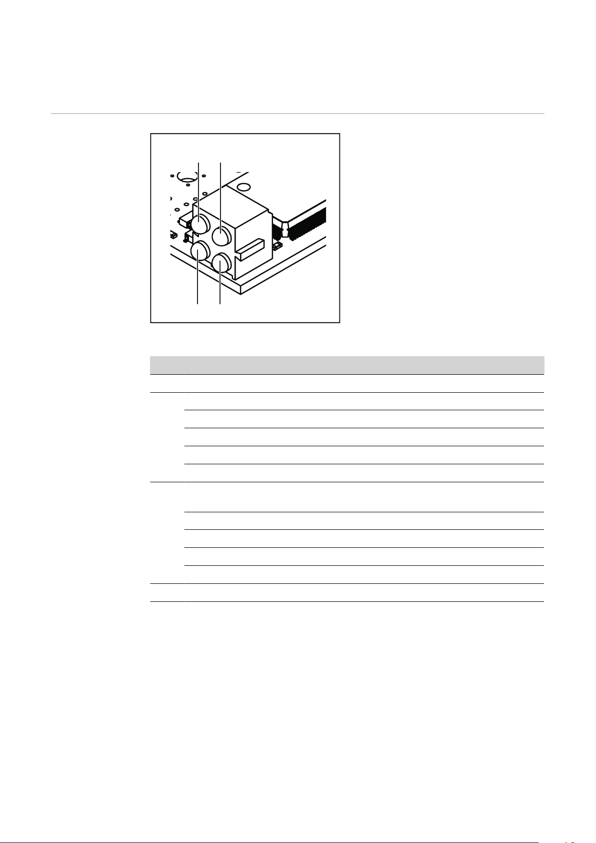
Gerätekonzept DeviceNet zeichnet sich durch geringes Bauvolumen und hohe Modularität aus.
(2) (3)
(4)
(1)
(6) (5)
(7)
(3)
(4)
(5)
(6) (7)
(8)
(9)
(10)
(2)(1)
Die direkte Verdrahtung von Aktoren und Sensoren ohne Querverbindungen zwischen den Klemmen standardisiert die Installation. Das einheitliche Beschriftungskonzept erleichtert die Installation.
Anschlüsse am
Interface
Anwendungsbeispiel
Anschlüsse am Interface
(1) Option externe Spannungsver-
sorgung
(2) Blindabdeckung
(3) Anschluss DeviceNet Enterprise
9-poliger Submin-Stecker zum
Anschluss des Datenkabels De-
viceNet Enterprise
(4) Blindabdeckung
(5) LocalNet Anschluss
zum Anschließen weiterer Sys-
temkomponenten
(6) LocalNet Anschluss
zum Anschließen weiterer Sys-
temkomponenten
(7) LocalNet Anschluss
zum Anschließen des Zwischen-
Schlauchpaketes
6
(1) Stromquelle
(2) Kühlgerät
(3) AB DeviceNet Enterprise
(4) Verbindungs-Schlauchpaket
(5) Datenkabel DeviceNet Enterprise
(6) Roboter-Steuerung
(7) Schweißdraht-Fass
(8) Roboter
(9) Schweißbrenner
(10) Drahtvorschub
Page 7

AB DeviceNet Enterprise anschließen und konfi-
(1)
(2)
(3)
(4)
(5)
gurieren
Sicherheit
WARNUNG!
Gefahr durch Fehlbedienung und fehlerhaft durchgeführte Arbeiten.
Schwere Personen- und Sachschäden können die Folge sein.
Alle in diesem Dokument beschriebenen Arbeiten und Funktionen dürfen
▶
nur von technisch geschultem Fachpersonal ausgeführt werden.
Dieses Dokument vollständig lesen und verstehen.
▶
Sämtliche Sicherheitsvorschriften und Benutzerdokumentationen dieses
▶
Gerätes und aller Systemkomponenten lesen und verstehen.
WARNUNG!
Gefahr durch elektrischen Strom.
Schwere Personen- und Sachschäden können die Folge sein.
Vor Beginn der Arbeiten alle beteiligten Geräte und Komponenten ausschal-
▶
ten und von Stromnetz trennen.
Alle beteiligten Geräte und Komponenten gegen Wiedereinschalten sichern.
▶
Nach dem Öffnen des Gerätes mit Hilfe eines geeigneten Messgerätes si-
▶
cherstellen, dass elektrisch geladene Bauteile (beispielsweise Kondensatoren) entladen sind.
DE
Allgemeines Anschließen und Konfigurieren des Interface AB DeviceNet Enterprise erfolgt
am Anybus-S DeviceNet Busmodul.
Anschlüsse, Einstellmöglichkeiten und Anzeigen am AnybusS DeviceNet
Busmodul
Anybus-S DeviceNet Busmodul
(1) Schnittstelle zum Print UBST 1
(2) Anschlussbuchse DeviceNet Enterprise
(3) TCP/IP-Konfigurationsschalter
(4) LED-Anzeige
(5) Statusanzeige Anybus-S
7
Page 8

Interface AB De-
(2)(1)
viceNet Enterprise anschließen
Interface AB DeviceNet Enterprise anschließen
LocalNet-Stecker vom Zwischen-
1
Schlauchpaket am Anschluss Local-Net (1) anschließen
HINWEIS! Solange das Roboterinterface am LocalNet angeschlossen ist, bleibt automatisch die Betriebsart „2-Takt Betrieb“gewählt
(Anzeige: Betriebsart 2-Takt Betrieb).
Nähere Informationen zur Betriebsart „Sonder-2-Takt Betrieb
für Roboterinterface“ finden Sie in
der Bedienungsanleitung der
Stromquelle.
Datenkabel DeviceNet Enterprise
2
am Anschluss DeviceNet Enterprise (2) anschließen
Steckerbelegung
für Anschluss
DeviceNet Enterprise (9-poliger Submin-Stecker)
Pin Belegung
1 Nicht in Verwendung
2 CAN_L
3 CAN_GND
4 Nicht in Verwendung
5 Nicht in Verwendung
6 GND
7 CAN_H
8 Nicht in Verwendung
9 CAN_V+
8
Page 9

Zusätzliche Si-
AB DeviceNet Enterprise
gnale konfigurieren
Die Konfiguration zusätzlicher Ein-/Ausgangssignale erfolgt mit dem FroniusProgramm ‘Servicemodul’:
Start / Programme / Fronius Product Group / Servicemodul
-
Eintrag AB DeviceNet Enterprise auswählen
-
Schaltfläche Konfiguration klicken
-
DE
‘System settings’ auswählen
-
Für die zusätzlichen Signale 105 - 112 unter ‘ROB I/O’ das Kontrollkäst-
-
chen ‘Connect’ aktivieren
Für die zusätzlichen Signale 113 - 200 unter ‘Part number’ das Kontrollkäst-
-
chen ‘Part number active’ aktivieren
WICHTIG! Sollen nur die zusätzlichen Signale 105 - 112 ohne die Signale 113 200 verwendet werden, so ist am Interface AB DeviceNet Enterprise folgende
Option erforderlich: ‘Einbauset Rob I/O’
Weitere Informationen zur Konfiguration sind im EDS-Datenblatt des Anybus-S
Device-Net Busmoduls enthalten.
9
Page 10

Mac ID einstellen
Die Einstellung der Mac ID erfolgt am
TCP/IP-Konfigurationsschalter mittels
der Dip-Schalter 3 - 8.
sw. = Dip-Schalter
TCP/IP-Konfigurationsschalter
Mac ID sw. 3 (MSB) sw. 4 sw. 5 sw. 6 sw. 7 sw. 8 (LSB)
0 OFF OFF OFF OFF OFF OFF
1 OFF OFF OFF OFF OFF ON
2 OFF OFF OFF OFF ON OFF
3 OFF OFF OFF OFF ON ON
Baud-Rate einstellen
... ... ... ... ... ... ...
62 ON ON ON ON ON OFF
63 ON ON ON ON ON ON
Die Einstellung der Baud-Rate erfolgt
am TCP/IP-Konfigurationsschalter mittels der Dip-Schalter 1 - 2.
sw. = Dip-Schalter
Baud-Rate sw. 1 sw. 2
125 kBit/s OFF OFF
250 kBit/s OFF ON
500 kBit/s ON OFF
reserviert ON ON
TCP/IP-Konfigurationsschalter
10
Page 11

Fehlerdiagnose, Fehlerbehebung am Print UBST1
(2)
(3)
(1)
(8)
(4)
(7)
(5)
(6)
Betriebszustand
LEDs am Print
UBST 1
DE
(1) LED „+5 V“
(2) LEDs „Traffic 1 - 4“
(3) LEDs „L1 - L7“
(4) LED „EXT“
LED „+5 V“ (1) Die LED „+5 V“ (1) leuchtet, wenn die interne oder die externe Versorgungsspan-
LEDs „Traffic 1 4“ (2)
nung angeschlossen ist. Die LED „+5 V“ zeigt an, dass die Print-Elektronik in Ordnung ist.
LED Anzeige Bedeutung Abhilfe
Traffic X aus oder
leuchtet
Traffic X blinkt Kommunikation am Fro-
Keine Kommunikation
am Fronius LocalNet
nius LocalNet aktiv
(5) Jumper „EXT“
(6) Jumper „INT“
(7) LED „INT“
(8) LED „VCC“
Versorgungsspannung
prüfen;
Verkabelung prüfen
-
11
Page 12

LEDs „L1 - L7“
(a) (b) (c)
(3)
LED Anzeige Bedeutung Abhilfe
L1 Leuchtet /
Blinkt
Fehler im Modul aufgetreten
Siehe Fehlernummer laut
Tabelle / Servicedienst
L2 Leuchtet Kommunikation am Fronius
-
LocalNet aktiv
L3 Blinkt Ethernet-Stack sendet Da-
-
ten
L6 Leuchtet Ethernet - Physikal. Verbin-
-
dung vorhanden
L7 Blinkt Ethernet-Datenübertra-
-
gung aktiv
LED „L1“ leuchtet:
Die Fehlerbeschreibung sowie die dazugehörende Display-Anzeige an der Stromquelle sind im Beiblatt ‘Roboter-Interface’ (42,0410,0616) beschrieben:
Kapitel ‘Ausgangssignale zum Roboter’, Abschnitt ‘Fehler-Nummer UBST’
LED „L1“ blinkt - Fehler wird über Blink-Code angezeigt:
(a) Schnelles Blinken:
Start des Fehlercodes
(b) Erste langsame Impulse:
Fehlerart
(c) Zweite langsame Impulse:
Fehlerstelle
Fehlercode
1 1 Max. EtherNet Framegröße über-
Fehlerargument Fehlerbeschreibung Abhilfe
Interface aus-
schritten
und einschalten
2 Falscher Mailbox-Typ -
4 UDP-Datenunterlauf auf Port 15000 -
5 UDP-Datenüberlauf -
6 UDP-Datenunterlauf auf 15001 -
7 Falscher UDP-Port -
8 Fehler bei der Stack-Initialisierung -
9 Ungültiger Funktionsaufruf -
LED „EXT“ (4) Die LED „EXT“ (4) leuchtet, wenn die externe Versorgungsspannung mittels Jum-
per „EXT“ (5) angewählt ist.
Jumper „EXT“
(5) / Jumper
„INT“ (6)
12
Die Jumper „EXT“ (5) und „INT“ (6) dienen zum Auswählen zwischen interner
und externer Spannungsversorgung. Im Auslieferungszustand befindet sich der
Jumper auf „externer Spannungsversorgung“.
Page 13

LED „INT“ (7) Die LED „INT“ (7) leuchtet, wenn die interne Versorgungsspannung mittels Jum-
per „INT“ (6) angewählt ist.
LED „VCC“ (8) Die LED „VCC“ (8) leuchtet, wenn die interne oder externe Versorgungsspannung
angeschlossen ist. Die LED „VCC“ zeigt an, dass die Spannungsversorgung + 24 V
für die Bauteil-Komponenten LocalNet-seitig in Richtung extern in Ordnung ist.
DE
13
Page 14
Fehlerdiagnose, Fehlerbehebung am Anybus-S
(2)
(4)
(1)
(3)
DeviceNet Busmodul
LED-Anzeige am
Anybus-S Device-Net Busmodul
(1) Reserve
(2) Netzwerk-Status
(3) Modus-Status
(4) Reserve
LED-Anzeige am Anybus-S DeviceNet Busmodul
LED Anzeige Bedeutung
1 - reserviert für andere Anwendungen
2 aus keine Stromversorgung / nicht online
leuchtet grün Verbindung in Ordnung, online
(3) aus keine Stromversorgung des Anybus-S DeviceNet Bus-
4 - reseviert für andere Anwendungen
blinkt grün online, keine Verbindung
leuchtet rot kritischer Verbindungsfehler
blinkt rot Verbindungs-Timeout
moduls
leuchtet grün Anybus-S DeviceNet Busmodul ist betriebsbereit
blinkt grün Datenmenge größer als konfiguriert
leuchtet rot schwerwiegende Störung
blinkt rot geringfügige Störung
14
Page 15

Statusanzeige
Anybus-S
Statusanzeige Anybus-S am Anybus-S Ethernet/IP Busmodul
Statusanzeige blinkt rot, 4 Hz
Fehler im DPRAM
Statusanzeige blinkt grün, 2 Hz
Busmodul nicht initialisiert
Die Statusanzeige Anybus-S ist eine
LED auf der Oberfläche des Anybus-S
Device-Net Busmoduls.
Folgende Fehler und Zustände werden
an der Statusanzeige Anybus-S angezeigt:
Statusanzeige leuchtet rot
Interner Fehler oder Betrieb im Bootloader-Modus
Statusanzeige blinkt rot, 1 Hz
Fehler im Konfigurationsspeicher RAM
Statusanzeige blinkt rot, 2 Hz
Fehler in ASIC oder FLASH
DE
Statusanzeige blinkt grün, 1 Hz
Busmodul initialisiert, ordnungsgemäßer Betrieb
15
Page 16

Eigenschaften der Datenübertragung und technische Daten
Eigenschaften
der Datenübertragung
Sicherheitseinrichtung
Netzwerk Topologie linearer Bus,
Busabschluss an beiden Enden (121 Ohm),
Stichleitungen möglich
Medium abgeschirmtes 2x2 adrig verdrilltes Kabel,
Schirmung muss ausgeführt werden
max. Anzahl der Teilnehmer 64
max. Bus-Länge, abhängig von
der eingestellten Baud-Rate
Busanschluss Open Style Connector 5-polig
Betriebsarten Bit Strobe, Polling, Cycling,
Prozessdaten-Breite 104 Bit (Standardkonfiguration)
Prozessdaten-Format Intel
Bei ausgefallener Datenübertragung werden alle Ein- und Ausgänge zurückgesetzt und die Stromquelle befindet sich im Zustand „Stop“. Nach wiederhergestellter Datenübertragung erfolgt die Wiederaufnahme des Vorganges durch folgende Signale:
Signal „Roboter ready“
-
Signal „Quellen-Störung quittieren“
-
100 m bei 500 kBit/s
250 m bei 250 kBit/s
500 m bei 125 kBit/s
Change of State (COS)
Technische Daten AB DeviceNet Enterprise
EDS-Datei Electronic Data
Sheet
Spannungsversorgung 24 V DC +/- 10% intern
Stromaufnahme 400 mA typ.
Einbaulage an der Rückseite der
Stromquellen:
Schutzart IP23
Konfigurations-Schnittstelle über Konfigurationsmodul Feldbus
Jedem Teilnehmer in einem DeviceNet-Netzwerk ist eine EDS-Datei zugeordnet.
Die EDS-Datei enthält alle Informationen über den Teilnehmer. Die EDS-Datei ist
für die Netzwerk-Konfiguration erforderlich und ist im Download-Bereich der folgenden Internet-Adresse verfügbar:
http://www.anybus.de/products/devicenet/Techn. Dokumentation/Configuration
file
TPS 3200 / 4000 / 5000
TS 4000 / 5000
16
Page 17

Signalbeschreibung AB DeviceNet Enterprise
Allgemeines Je nach eingestellter Betriebsart kann das Interface AB DeviceNet Enterprise
verschiedenste Ein- und Ausgangssignale übertragen.
DE
Betriebsarten
der Stromquelle
Übersicht ‘Signalbeschreibung AB DeviceNet Enterprise’ setzt sich aus folgenden Ab-
Betriebsart E05 E04 E03
MIG/MAG Standard-Synergic Schweißen 0 0 0
MIG/MAG Puls-Synergic Schweißen 0 0 1
Job Betrieb 0 1 0
Parameteranwahl intern 0 1 1
MIG/MAG Standard-Manuell Schweißen 1 0 0
CC / CV 1 0 1
WIG Schweißen 1 1 0
CMT / Sonderprozess 1 1 1
schnitten zusammen:
Ein- und Ausgangssignale für MIG/MAG Standard-/Puls-Synergic und CMT
-
Ein- und Ausgangssignale für WIG
-
Ein- und Ausgangssignale für CC/CV
-
Ein- und Ausgangssignale für Standard-Manuell
-
17
Page 18

Ein- und Ausgangssignale für MIG/MAG Standard-/Puls-Synergic und CMT
Eingangssignale
(vom Roboter
zur Stromquelle)
Lfd. Nr. Signalbezeichnung Bereich Aktivität
E01 Schweißen Ein - High
E02 Roboter bereit - High
E03 Betriebsarten Bit 0 - High
E04 Betriebsarten Bit 1 - High
E05 Betriebsarten Bit 2 - High
E06 Master-Kennung Twin - High
E07 Nicht in Verwendung - -
E08 Nicht in Verwendung - -
E09 Gas Test - High
E10 Drahtvorlauf - High
E11 Drahtrücklauf - High
E12 Quellenstörung quittieren - High
E13 Positionssuchen - High
E14 Brenner ausblasen - High
E15 Nicht in Verwendung - -
E16 Nicht in Verwendung - -
E17- E24 Job-Nummer 0 - 99 -
E25 - E31 Programmnummer 0 - 127 -
E32 Schweißsimulation - High
Mit RCU 5000i und in Betriebsart Jobbetrieb
E17- E31 Job-Nummer 0 - 999 -
E32 Schweißsimulation - High
Leistungs-Sollwert 0 - 65535 (0 - 100
%)
E33-E40 Low Byte - -
E41-E48 High Byte - -
Lichtbogen-Längenkorrektur-,
Sollwert
0 - 65535 (-30 - +30%)-
-
18
E49-E56 Low Byte - -
Page 19

Lfd. Nr. Signalbezeichnung Bereich Aktivität
E57-E64 High Byte - -
E65-E72
Puls- oder Dynamikkorrektur
1)
0 - 255 (-5 - +5 %) -
Sollwert
E73-E80 Rückbrand-Sollwert 0 - 255 (-200 - +200
-
ms)
Schweißgeschwindigkeit 0 - 32767 (0-3276
-
cm/min)
E81 - E88 Nicht in Verwendung - -
E89 - E96 Nicht in Verwendung - -
E97 Synchro Puls disable - High
E98 SFI disable - High
E99
Puls- oder Dynamikkorrektur
1)
- High
disable
E100 Rückbrand disable - High
DE
Zusätzliche Eingangssignale ‘Rob I/O’ (vom
Roboter zur
Stromquelle)
E101 Leistungs-Vollbereich (0 - 30 m) - High
E102-104 Nicht in Verwendung - -
1)
Je nach ausgewähltem Verfahren und eingestelltem Schweißprogramm
werden unterschiedliche Parameter vorgegeben:
Verfahren Parameter
Puls Pulskorrektur
Standard Dynamikkorrektur
CMT Hotstart-Zeit
Pulskorrektur
Hotstart Pulszyklen
Boost-Korrektur
Dynamikkorrektur
Lfd. Nr. Signalbezeichnung Bereich Aktivität
E105 ROB I/O Output 1 - High
E106 ROB I/O Output 2 - High
E107-112 Nicht in Verwendung - -
19
Page 20

Zusätzliche Eingangssignale ‘Bauteil-Nummer’ (vom Roboter zur Stromquelle)
Lfd. Nr. Signalbezeichnung Bereich Aktivität
E113-120 Bauteil-Nummer, Typ 1 ASCII 32 - 254 -
E121-128 Bauteil-Nummer, Typ 2 ASCII 32 - 254 -
E129-136 Bauteil-Nummer, Typ 3 ASCII 32 - 254 -
E137-144 Bauteil-Nummer, Typ 4 ASCII 32 - 254 -
E145-152 Bauteil-Nummer, Typ 5 ASCII 32 - 254 -
E153-160 Bauteil-Nummer, Typ 6 ASCII 32 - 254 -
E161-168 Bauteil-Nummer, Typ 7 ASCII 32 - 254 -
E169-176 Bauteil-Nummer, Typ 8 ASCII 32 - 254 -
E177-184 Bauteil-Nummer, Typ 9 ASCII 32 - 254 -
E185-192 Bauteil-Nummer, Typ 10 ASCII 32 - 254 -
E193-200 Bauteil-Nummer, Typ 11 ASCII 32 - 254 -
Ausgangssignale
(von der Stromquelle zum Roboter)
Lfd. Nr. Signalbezeichnung Bereich Aktivität
A01 Lichtbogen stabil - High
A02 Limit-Signal (nur in Verbindung
mit RCU 5000i)
A03 Prozess aktiv - High
A04 Hauptstrom-Signal - High
A05 Brenner-Kollisionsschutz - High
A06 Stromquelle bereit - High
A07 Kommunikation bereit - High
A08 Nicht in Verwendung - -
A09 - A16 Error-Nummer 0 - 255 -
A17 - A24 Nicht in Verwendung - -
A25 Festbrand-Kontrolle - High
A26 Nicht in Verwendung - -
A27 Roboter-Zugriff (nur in Verbin-
dung mit RCU 5000i)
A28 Draht vorhanden - High
- High
- High
20
A29 Kurzschluss Zeitüberschreitung - High
A30 Daten Dokumentation bereit
(nur mit RCU 5000i)
A31 Nicht in Verwendung - -
A32 Leistung außerhalb Bereich - -
Schweißspannung (Istwert) 0 - 65535
A33 - A40 Low Byte - -
- High
-
(0 - 100 V)
Page 21

Lfd. Nr. Signalbezeichnung Bereich Aktivität
A41 - A48 High Byte - -
Schweißstrom (Istwert) 0 - 65535
-
(0 - 1000 A)
A49 - A56 Low Byte - -
A57 - A64 High Byte - -
A65 - A72 Motorstrom (Istwert) 0 - 255
-
(0 - 5 A)
A73 - A80 Nicht verwendet - -
Drahtgeschwindigkeit (Istwert) 0 - 65535
(-327,68 - +327,67
0 - vD
max
)
A81 - A88 Low Byte - -
A89 - A96 High Byte - -
A97 Limitüberschreitung vD - High
A98 Limitunterschreitung vD - High
DE
Zusätzliche Ausgangssignale ‘Rob I/O’ (vom
Roboter zur
Stromquelle
A99 Limitüberschreitung
- High
Schweißstrom
A100 Limitunterschreitung
- High
Schweißstrom
A101 Limitüberschreitung
- High
Schweißspannung
A102 Limitunterschreitung
- High
Schweißspannung
A103 Limitüberschreitung
- High
Hauptmotor
A104 Limitunterschreitung
- High
Hauptmonitor
Lfd. Nr. Signalbezeichnung Bereich Aktivität
A105 ROB I/O Input 1 - High
A106 ROB I/O Input 2 - High
A107 ROB I/O Input 3 - High
A108 ROB I/O Input 4 - High
A109-112 Nicht in Verwendung - -
21
Page 22

Zusätzliche Ausgangssignale ‘Bauteil-Nummer’ (vom Roboter zur Stromquelle)
Lfd. Nr. Signalbezeichnung Bereich Aktivität
A113-120 Nicht in Verwendung - -
A121-128 Nicht in Verwendung - -
A129-136 Nicht in Verwendung - -
A137-144 Nicht in Verwendung - -
A145-152 Nicht in Verwendung - -
A153-160 Nicht in Verwendung - -
A161-168 Nicht in Verwendung - -
A169-176 Nicht in Verwendung - -
A177-184 Nicht in Verwendung - -
A185-192 Nicht in Verwendung - -
A193-200 Nicht in Verwendung - -
22
Page 23

Ein- und Ausgangssignale für WIG
DE
WIG Eingangssignale (vom Roboter zur Stromquelle)
Lfd. Nr. Signalbezeichnung Bereich Aktivität
E01 Schweißen Ein - High
E02 Roboter bereit - High
E03 Betriebsarten Bit 0 - High
E04 Betriebsarten Bit 1 - High
E05 Betriebsarten Bit 2 - High
E06 Master-Kennung Twin - High
E07 Nicht in Verwendung - -
E08 Nicht in Verwendung - -
E09 Gas Test - High
E10 Drahtvorlauf - High
E11 Drahtrücklauf - High
E12 Quellenstörung quittieren - High
E13 Positionssuchen - High
E14 KD disable - High
E15 Nicht in Verwendung - -
E16 Nicht in Verwendung - -
E17- E24 Job-Nummer 0 - 99 -
E25 DC/AC - High
E26 DC- / DC+ - High
E27 Kalottenbildung - High
E28 Pulsen disable - High
E29 Pulsbereichs-Auswahl Bit 0 - High
E30 Pulsbereichs-Auswahl Bit 1 - High
E31 Pulsbereichs-Auswahl Bit 2 - High
E32 Schweißsimulation - High
Hauptstrom (Sollwert) 0 - 65535 (0 - I
E33 - E40 Low Byte - -
E41 - E48 High Byte - -
max
) -
Externer Parameter (Sollwert) 0 - 65535
E49 - E56 Low Byte - -
E57 - E64 High Byte - -
23
Page 24

Lfd. Nr. Signalbezeichnung Bereich Aktivität
E65 - E72 Grundstrom (Sollwert) 0 - 255 (0 - 100 %) -
E73 - E80 Duty Cycle (Sollwert) 0 - 255 (10 - 90 %) -
Zusätzliche Eingangssignale ‘Rob I/O’ (vom
Roboter zur
Stromquelle)
Drahtgeschwindigkeit Fd.1
0 - 65535 (0 - vD
max
) -
(Sollwert)
E81 - E88 Low Byte - -
E89 - E96 High Byte - -
E97 - E98 Nicht in Verwendung - -
E99 Grundstrom disable - High
E100 Duty Cycle disable - High
E101-104 Nicht in Verwendung - -
Lfd. Nr. Signalbezeichnung Bereich Aktivität
E105 ROB I/O Output 1 - High
E106 ROB I/O Output 2 - High
E107-112 Nicht in Verwendung - -
Zusätzliche Eingangssignale ‘Bauteil-Nummer’ (vom Roboter zur Stromquelle)
Lfd. Nr. Signalbezeichnung Bereich Aktivität
E113-120 Bauteil-Nummer, Typ 1 ASCII 32 - 254 -
E121-128 Bauteil-Nummer, Typ 2 ASCII 32 - 254 -
E129-136 Bauteil-Nummer, Typ 3 ASCII 32 - 254 -
E137-144 Bauteil-Nummer, Typ 4 ASCII 32 - 254 -
E145-152 Bauteil-Nummer, Typ 5 ASCII 32 - 254 -
E153-160 Bauteil-Nummer, Typ 6 ASCII 32 - 254 -
E161-168 Bauteil-Nummer, Typ 7 ASCII 32 - 254 -
E169-176 Bauteil-Nummer, Typ 8 ASCII 32 - 254 -
E177-184 Bauteil-Nummer, Typ 9 ASCII 32 - 254 -
E185-192 Bauteil-Nummer, Typ 10 ASCII 32 - 254 -
E193-200 Bauteil-Nummer, Typ 11 ASCII 32 - 254 -
24
Page 25

WIG Einstellung
Puls-Bereich
Bereichsauswahl E31 E30 E29
Puls-Bereich an der Stromquelle
einstellen
Einstellbereich Puls deaktiviert 0 0 1
0,2 - 2 Hz 0 1 0
2 - 20 Hz 0 1 1
20 - 200 Hz 1 0 0
200 - 2000 Hz 1 0 1
0 0 0
DE
Ausgangssignale
(von der Stromquelle zum Roboter)
Lfd. Nr. Signalbezeichnung Bereich Aktivität
A01 Lichtbogen stabil - High
A02 Nicht in Verwendung - -
A03 Prozess aktiv - High
A04 Hauptstrom-Signal - High
A05 Brenner-Kollisionsschutz - High
A06 Stromquelle bereit - High
A07 Kommunikation bereit - High
A08 Reserve - -
A09 - A16 Fehlernummer 0 - 255 -
A17 - A24 Nicht in Verwendung - -
A25 Nicht in Verwendung - -
A26 Hochfrequenz aktiv - High
A27 Nicht in Verwendung - -
A28 Draht vorhanden - High
A29 Nicht in Verwendung - -
A30 Nicht in Verwendung - -
A31 Puls High - High
A32 Nicht in Verwendung - -
Schweißspannung (Istwert) 0 - 65535
(0 - 100 V)
A33 - A40 Low Byte - -
A41 - A48 High Byte - -
Schweißstrom (Istwert) 0 - 65535
(0 - 1000 A)
A49 - A56 Low Byte - -
A57 - A64 High Byte - -
-
-
25
Page 26

Lfd. Nr. Signalbezeichnung Bereich Aktivität
Zusätzliche Ausgangssignale ‘Rob I/O’ (vom
Roboter zur
Stromquelle)
A65 - A72 Motorstrom (Istwert) 0 - 255
-
(0 - 5 A)
A73 - A80 Lichtbogen-Länge (Istwert)
0 - 255 -
(AVC)
Drahtgeschwindigkeit (Istwert) 0 - 65535
(0 - vD
max
)
A81 - A88 Low Byte - -
A89 - A96 High Byte - -
A97 - E104 Nicht in Verwendung - -
Lfd. Nr. Signalbezeichnung Bereich Aktivität
A105 ROB I/O Input 1 - High
A106 ROB I/O Input 2 - High
A107 ROB I/O Input 3 - High
Zusätzliche Ausgangssignale ‘Bauteil-Nummer’ (vom Roboter zur Stromquelle)
A108 ROB I/O Input 4 - High
A109-112 Nicht in Verwendung - -
Lfd. Nr. Signalbezeichnung Bereich Aktivität
A113-120 Nicht in Verwendung - -
A121-128 Nicht in Verwendung - -
A129-136 Nicht in Verwendung - -
A137-144 Nicht in Verwendung - -
A145-152 Nicht in Verwendung - -
A153-160 Nicht in Verwendung - -
A161-168 Nicht in Verwendung - -
A169-176 Nicht in Verwendung - -
A177-184 Nicht in Verwendung - -
A185-192 Nicht in Verwendung - -
A193-200 Nicht in Verwendung - -
26
Page 27

Ein- und Ausgangssignale für CC/CV
DE
Eingangssignale
(vom Roboter
zur Stromquelle)
Lfd. Nr. Signalbezeichnung Bereich Aktivität
E01 Schweißen Ein - High
E02 Roboter bereit - High
E03 Betriebsarten Bit 0 - High
E04 Betriebsarten Bit 1 - High
E05 Betriebsarten Bit 2 - High
E06 Master-Kennung Twin - High
E07 Nicht in Verwendung - -
E08 Nicht in Verwendung - -
E09 Gas Test - High
E10 Drahtvorlauf - High
E11 Drahtrücklauf - High
E12 Quellenstörung quittieren - High
E13 Positionssuchen - High
E14 Brenner ausblasen - High
E15 - E16 Nicht in Verwendung - -
E17- E24 Job-Nummer 0 - 99 -
E25 - E31 Nicht in Verwendung - -
E32 Schweißsimulation - High
Schweißstrom-Sollwert 0 - 65535 (0 - max.) -
E33-E40 Low Byte - -
E41-E48 High Byte - -
Drahtgeschwindigkeit 0 - 65535 (-30 - +30%)-
E49-E56 Low Byte - -
E57-E64 High Byte - -
E65-E72 Schweißsapnnung 0 - 255 (-5 - +5 %) -
E73-E80 Nicht in Verwendung - -
E81 - E88 Low Byte - -
E89 - E96 High Byte - -
E97 - 104 Nicht in Verwendung - -
27
Page 28

Zusätzliche Eingangssignale ‘Rob I/O’ (vom
Roboter zur
Stromquelle)
Lfd. Nr. Signalbezeichnung Bereich Aktivität
E105 ROB I/O Output 1 - High
E106 ROB I/O Output 2 - High
E107-112 Nicht in Verwendung - -
Zusätzliche Eingangssignale ‘Bauteil-Nummer’ (vom Roboter zur Stromquelle)
Ausgangssignale
(von der Stromquelle zum Roboter)
Lfd. Nr. Signalbezeichnung Bereich Aktivität
E113-120 Bauteil-Nummer, Typ 1 ASCII 32 - 254 -
E121-128 Bauteil-Nummer, Typ 2 ASCII 32 - 254 -
E129-136 Bauteil-Nummer, Typ 3 ASCII 32 - 254 -
E137-144 Bauteil-Nummer, Typ 4 ASCII 32 - 254 -
E145-152 Bauteil-Nummer, Typ 5 ASCII 32 - 254 -
E153-160 Bauteil-Nummer, Typ 6 ASCII 32 - 254 -
E161-168 Bauteil-Nummer, Typ 7 ASCII 32 - 254 -
E169-176 Bauteil-Nummer, Typ 8 ASCII 32 - 254 -
E177-184 Bauteil-Nummer, Typ 9 ASCII 32 - 254 -
E185-192 Bauteil-Nummer, Typ 10 ASCII 32 - 254 -
E193-200 Bauteil-Nummer, Typ 11 ASCII 32 - 254 -
Lfd. Nr. Signalbezeichnung Bereich Aktivität
A01 Lichtbogen stabil - High
A02 Limit-Signal (nur in Verbindung
mit RCU 5000i)
- High
A03 Prozess aktiv - High
A04 Hauptstrom-Signal - High
A05 Brenner-Kollisionsschutz - High
A06 Stromquelle bereit - High
A07 Kommunikation bereit - High
A08 Nicht in Verwendung - -
A09 - A16 Error-Nummer 0 - 255 -
A17 - A24 Nicht in Verwendung - -
A25 Festbrand-Kontrolle - High
A26 Nicht in Verwendung - -
A27 Roboter-Zugriff (nur in Verbin-
dung mit RCU 5000i)
A28 Draht vorhanden - High
A29 Kurzschluss Zeitüberschreitung - High
- High
28
Page 29

Lfd. Nr. Signalbezeichnung Bereich Aktivität
A30 Daten Dokumentation bereit
- High
(nur mit RCU 5000i)
A31 Nicht in Verwendung - -
A32 Leistung außerhalb Bereich - High
Schweißspannung (Istwert) 0 - 65535
-
(0 - 100 V)
A33 - A40 Low Byte - -
A41 - A48 High Byte - -
Schweißstrom (Istwert) 0 - 65535
-
(0 - 1000 A)
A49 - A56 Low Byte - -
A57 - A64 High Byte - -
A65 - A72 Motorstrom (Istwert) 0 - 255
-
(0 - 5 A)
A73 - A80 Nicht verwendet - -
DE
Drahtgeschwindigkeit (Istwert) 0 - 65535
(-327,68 - +327,67
0 - vD
max
)
A81 - A88 Low Byte - -
A89 - A96 High Byte - -
A97 Limitüberschreitung vD - High
A98 Limitunterschreitung vD - High
A99 Limitüberschreitung
- High
Schweißstrom
A100 Limitunterschreitung
- High
Schweißstrom
A101 Limitüberschreitung
- High
Schweißspannung
A102 Limitunterschreitung
- High
Schweißspannung
A103 Limitüberschreitung Hauptmo-
- High
nitor
A104 Limitunterschreitung PushPull-
- High
Motor
29
Page 30

Zusätzliche Ausgangssignale ‘Rob I/O’ (vom
Roboter zur
Stromquelle
Lfd. Nr. Signalbezeichnung Bereich Aktivität
A105 ROB I/O Input 1 - High
A106 ROB I/O Input 2 - High
A107 ROB I/O Input 3 - High
A108 ROB I/O Input 4 - High
A109-112 Nicht in Verwendung - -
Zusätzliche Ausgangssignale ‘Bauteil-Nummer’ (vom Roboter zur Stromquelle)
Lfd. Nr. Signalbezeichnung Bereich Aktivität
A113-120 Nicht in Verwendung - -
A121-128 Nicht in Verwendung - -
A129-136 Nicht in Verwendung - -
A137-144 Nicht in Verwendung - -
A145-152 Nicht in Verwendung - -
A153-160 Nicht in Verwendung - -
A161-168 Nicht in Verwendung - -
A169-176 Nicht in Verwendung - -
A177-184 Nicht in Verwendung - -
A185-192 Nicht in Verwendung - -
A193-200 Nicht in Verwendung - -
30
Page 31

Ein- und Ausgangssignale für Standard-Manuell
DE
Eingangssignale
(vom Roboter
zur Stromquelle)
Lfd. Nr. Signalbezeichnung Bereich Aktivität
E01 Schweißen Ein - High
E02 Roboter bereit - High
E03 Betriebsarten Bit 0 - High
E04 Betriebsarten Bit 1 - High
E05 Betriebsarten Bit 2 - High
E06 Master-Kennung Twin - High
E07 Nicht in Verwendung - -
E08 Nicht in Verwendung - -
E09 Gas Test - High
E10 Drahtvorlauf - High
E11 Drahtrücklauf - High
E12 Quellenstörung quittieren - High
E13 Positionssuchen - High
E14 Brenner ausblasen - High
E15 Nicht in Verwendung - -
E16 Nicht in Verwendung - -
E17- E24 Nicht in Verwendung - -
E25 - E31 Programmnummer 0 - 127 -
E32 Schweißsimulation - High
Drahtgeschwindigkeit 0 - 65535 (-327,67 -
+327,67 m/min)
E33-E40 Low Byte - -
E41-E48 High Byte - -
Schweißspannung 0 - 65535 (0 - U
E49-E56 Low Byte - -
E57-E64 High Byte - -
E65-E72 Dynamikkorrektur 0 - 255 (-5 - +5 %) -
max
-
) -
E73-E80 Rückbrand-Sollwert 0 - 255 (-200 - +200
ms)
-
31
Page 32

Lfd. Nr. Signalbezeichnung Bereich Aktivität
Nicht in Verwendung - -
E81 - E88 Low Byte - -
E89 - E96 High Byte - -
E97 Nicht in Verwendung - -
E98 Nicht in Verwendung - -
E99
Puls- oder Dynamikkorrektur
1)
- High
disable
E100 Rückbrand disable - High
E101 Leistungs-Vollbereich (0 - 30 m) - High
E102-104 Nicht in Verwendung - -
Zusätzliche Eingangssignale ‘Rob I/O’ (vom
Roboter zur
Stromquelle)
Zusätzliche Eingangssignale ‘Bauteil-Nummer’ (vom Roboter zur Stromquelle)
Lfd. Nr. Signalbezeichnung Bereich Aktivität
E105 ROB I/O Output 1 - High
E106 ROB I/O Output 2 - High
E107-112 Nicht in Verwendung - -
Lfd. Nr. Signalbezeichnung Bereich Aktivität
E113-120 Bauteil-Nummer, Typ 1 ASCII 32 - 254 -
E121-128 Bauteil-Nummer, Typ 2 ASCII 32 - 254 -
E129-136 Bauteil-Nummer, Typ 3 ASCII 32 - 254 -
E137-144 Bauteil-Nummer, Typ 4 ASCII 32 - 254 -
E145-152 Bauteil-Nummer, Typ 5 ASCII 32 - 254 -
E153-160 Bauteil-Nummer, Typ 6 ASCII 32 - 254 -
E161-168 Bauteil-Nummer, Typ 7 ASCII 32 - 254 -
E169-176 Bauteil-Nummer, Typ 8 ASCII 32 - 254 -
E177-184 Bauteil-Nummer, Typ 9 ASCII 32 - 254 -
32
E185-192 Bauteil-Nummer, Typ 10 ASCII 32 - 254 -
E193-200 Bauteil-Nummer, Typ 11 ASCII 32 - 254 -
Page 33

Ausgangssignale
(von der Stromquelle zum Roboter)
Lfd. Nr. Signalbezeichnung Bereich Aktivität
A01 Lichtbogen stabil - High
A02 Limit-Signal (nur in Verbindung
- High
mit RCU 5000i)
A03 Prozess aktiv - High
A04 Hauptstrom-Signal - High
A05 Brenner-Kollisionsschutz - High
A06 Stromquelle bereit - High
A07 Kommunikation bereit - High
A08 Nicht in Verwendung - -
A09 - A16 Error-Nummer 0 - 255 -
A17 - A24 Nicht in Verwendung - -
A25 Festbrand-Kontrolle - High
A26 Nicht in Verwendung - -
DE
A27 Roboter-Zugriff (nur in Verbin-
- High
dung mit RCU 5000i)
A28 Draht vorhanden - High
A29 Kurzschluss Zeitüberschreitung - High
A30 Daten Dokumentation bereit
- High
(nur mit RCU 5000i)
A31 Nicht in Verwendung - -
A32 Leistung außerhalb Bereich - High
Schweißspannung-Istwert 0 - 65535
-
(0 - 100 V)
A33 - A40 Low Byte - -
A41 - A48 High Byte - -
Schweißstrom-Istwert 0 - 65535
-
(0 - 1000 A)
A49 - A56 Low Byte - -
A57 - A64 High Byte - -
A65 - A72 Motorstrom (Istwert) 0 - 255
(0 - 5 A)
A73 - A80 Nicht verwendet - -
Drahtgeschwindigkeit 0 - 65535
(-327,68 - +327,67
0 - vD
max
)
A81 - A88 Low Byte - -
A89 - A96 High Byte - -
-
33
Page 34

Lfd. Nr. Signalbezeichnung Bereich Aktivität
A97 Limitüberschreitung vD - High
A98 Limitunterschreitung vD - High
Zusätzliche Ausgangssignale ‘Rob I/O’ (vom
Roboter zur
Stromquelle
A99 Limitüberschreitung
Schweißstrom
A100 Limitunterschreitung
Schweißstrom
A101 Limitüberschreitung
Schweißspannung
A102 Limitunterschreitung
Schweißspannung
A103 Limitüberschreitung Hauptmo-
tor
A104 Limitunterschreitung PushPull-
Motor
Lfd. Nr. Signalbezeichnung Bereich Aktivität
A105 ROB I/O Input 1 - High
A106 ROB I/O Input 2 - High
A107 ROB I/O Input 3 - High
- High
- High
- High
- High
- High
- High
Zusätzliche Ausgangssignale ‘Bauteil-Nummer’ (vom Roboter zur Stromquelle)
A108 ROB I/O Input 4 - High
A109-112 Nicht in Verwendung - -
Lfd. Nr. Signalbezeichnung Bereich Aktivität
A113-120 Nicht in Verwendung - -
A121-128 Nicht in Verwendung - -
A129-136 Nicht in Verwendung - -
A137-144 Nicht in Verwendung - -
A145-152 Nicht in Verwendung - -
A153-160 Nicht in Verwendung - -
A161-168 Nicht in Verwendung - -
A169-176 Nicht in Verwendung - -
A177-184 Nicht in Verwendung - -
A185-192 Nicht in Verwendung - -
A193-200 Nicht in Verwendung - -
34
Page 35

Schaltplan
DE
35
Page 36

36
Page 37

Contents
General 39
Safety 39
Basics 39
Application area 39
DeviceNet functions 39
Device concept 40
Interface connections 40
Example of application 40
Connecting and configuring the AB DeviceNet Enterprise 41
Safety 41
General 41
Connections, settings and displays on the Anybus-S Device-Net bus module 41
Connecting the AB DeviceNet Enterprise interface 42
Pin assignments for DeviceNet Enterprise socket (9-pin sub-D plug) 42
Configuring additional signals 43
Setting the Mac ID 44
Setting the baud rate 44
Troubleshooting the UBST1 PC board 45
Operating status LEDs on the UBST 1 board 45
„+5 V“ LED (1) 45
„Traffic 1 - 4“ LEDs (2) 45
„L1 - L7“ LEDs (3) 46
„EXT“ LED (4) 46
„EXT“ jumper (5) / “INT“ jumper (6) 46
„INT“ LED (7) 47
„VCC“ LED (8) 47
Troubleshooting the Anybus-S DeviceNet bus module 48
LED indicator on Anybus-S Device-Net bus module 48
Anybus-S status indicator 49
Data transfer properties and technical data 50
Data transmission properties 50
Safety features 50
AB DeviceNet Enterprise technical data 50
EDS file - Electronic Data Sheet 50
AB DeviceNet Enterprise signal description 51
General 51
Power source modes 51
Overview 51
Input and output signals for MIG/MAG standard pulse synergic and CMT 52
Input signals (from robot to power source) 52
Additional ‘Rob I/O’ input signals (from robot to power source) 53
Additional ‘part number’ input signals (from robot to power source) 54
Output signals (from power source to robot) 54
Additional ‘Rob I/O’ output signals (from robot to power source) 55
Additional ‘part number’ output signals (from robot to power source) 55
Input and output signals for TIG 57
TIG input signals (from robot to power source) 57
Additional ‘Rob I/O’ input signals (from robot to power source) 58
Additional ‘part number’ input signals (from robot to power source) 58
TIG pulse range settings 59
Output signals (from power source to robot) 59
Additional ‘Rob I/O’ output signals (from robot to power source) 60
Additional ‘part number’ output signals (from robot to power source) 60
Input and output signals for CC/CV 61
Input signals (from robot to power source) 61
Additional ‘Rob I/O’ input signals (from robot to power source) 62
Additional ‘part number’ input signals (from robot to power source) 62
Output signals (from power source to robot) 62
Additional ‘Rob I/O’ output signals (from robot to power source) 63
Additional ‘part number’ output signals (from robot to power source) 64
EN
37
Page 38

Input and output signals for standard manual 65
Input signals (from robot to power source) 65
Additional ‘Rob I/O’ input signals (from robot to power source) 66
Additional ‘part number’ input signals (from robot to power source) 66
Output signals (from power source to robot) 67
Additional ‘Rob I/O’ output signals (from robot to power source) 68
Additional ‘part number’ output signals (from robot to power source) 68
Circuit diagram 69
38
Page 39

General
Safety
Danger from incorrect operation and work that is not carried out properly.
This can result in serious personal injury and damage to property.
▶
▶
▶
Basics DeviceNet is an open, CAN-based system. DeviceNet employs a standard applica-
tion layer that allows the CAN protocol to be used in industrial applications.
The ‘AB DeviceNet Enterprise’ interface contains all the analog and digital components required for an efficient DeviceNet interface. The AB module has been
certified by ODVA (Open DeviceNet Vendor Association) and tested for interoperability with all leading DeviceNet modules. ‘AB DeviceNet Enterprise’ handles
automatically all DeviceNet bus traffic, thus relieving the main processor in the
automation device of all DeviceNet protocol processing.
WARNING!
All the work and functions described in this document must only be carried
out by technically trained and qualified personnel.
Read and understand this document in full.
Read and understand all safety rules and user documentation for this device
and all system components.
EN
Application area The ‘AB DeviceNet Enterprise’ interface is optimised for use in high-performance
automation devices and is used whenever high volumes of data need to be transmitted at high speeds.
DeviceNet functions
The ‘AB DeviceNet Enterprise’ interface supports baud rates from 125 to 500
kbit/s and implements the full range of functions of a DeviceNet adapter for implicit and explicit messaging.
The DeviceNet interface is completely electrically isolated. The following features are supported
‘Polled I/O’
-
‘Bitstrobed I/O’
-
‘Change of State’
-
‘Cyclic I/O’.
-
In addition to the standard DeviceNet objects ‘Identity’, ‘Message Router’, ‘DeviceNet’, ‘Assembly’, ‘Connection’ and ‘Acknowledge Handler’, the following manufacturer-specific objects have been predefined:
‘I/O Data Input’, ‘I/O Data Output’
-
‘Diagnostic’
-
‘Parameter Input’, ‘Parameter Output’
-
Other manufacturer-specific objects can be added on an application by application basis. The DeviceNet Mac_ID (station address) and baud rate can be set using
the DIP switches on the front of the module or in the software via the application
interface.
39
Page 40

Device concept DeviceNet is characterised by its low construction volume and high modularity.
(2) (3)
(4)
(1)
(6) (5)
(7)
(3)
(4)
(5)
(6) (7)
(8)
(9)
(10)
(2)(1)
The direct cabling of actuators and sensors without any interconnections between the terminals makes installation very staightforward. The uniform labelling
concept further simplifies the installation.
Interface connections
Example of application
Interface connections
(1) External power supply option
(2) Blanking cover
(3) DeviceNet Enterprise connec-
tion
9-pin sub-D plug for connecting
the DeviceNet Enterprise data
cable
(4) Blanking cover
(5) LocalNet connection
for connecting other system
components
(6) LocalNet connection
for connecting other system
components
(7) LocalNet connection
for connecting other system
components
40
(1) Power source
(2) Cooling unit
(3) AB DeviceNet Enterprise
(4) Interconnecting hosepack
(5) DeviceNet Enterprise data cable
(6) Robot control
(7) Welding wire drum
(8) Robot
(9) Welding torch
(10) Wirefeeder
Page 41

Connecting and configuring the AB DeviceNet
(1)
(2)
(3)
(4)
(5)
Enterprise
Safety
WARNING!
Danger from incorrect operation and work that is not carried out properly.
This can result in serious personal injury and damage to property.
All the work and functions described in this document must only be carried
▶
out by technically trained and qualified personnel.
Read and understand this document in full.
▶
Read and understand all safety rules and user documentation for this device
▶
and all system components.
WARNING!
Danger from electrical current.
This can result in serious personal injury and damage to property.
Before starting work, switch off all devices and components involved and dis-
▶
connect them from the grid.
Secure all devices and components involved so they cannot be switched back
▶
on.
After opening the device, use a suitable measuring instrument to check that
▶
electrically charged components (such as capacitors) have been discharged.
EN
General Connecting and configuring the AB Profibus DP interface is performed on the
Anybus-S DeviceNet bus module.
Connections,
settings and displays on the
Anybus-S Device-Net bus module
Anybus-S DeviceNet bus module
(1) Interface to UBST 1 board
(2) DeviceNet Enterprise connection socket
(3) TCP/IP configuration switch
(4) LED indicator
(5) Anybus-S status indicator
41
Page 42

Connecting the
(2)(1)
AB DeviceNet
Enterprise interface
Connecting the AB DeviceNet Enterprise interface
Connect LocalNet plug on inter-
1
mediate hosepack to LocalNet
connection (1)
NOTE! While the robot interface is
connected to the LocalNet, „2-step
mode“ remains selected (display: 2step mode).
Further information on the „special
2-step mode for robot interface“
can be found in the power source
operating instructions.
Connect the DeviceNet Enterprise
2
data cable to the DeviceNet Enterprise socket (2)
Pin assignments
for DeviceNet
Enterprise socket (9-pin subD plug)
Pin Assignment
1 Not in use
2 CAN_L
3 CAN_GND
4 Not in use
5 Not in use
6 GND
7 CAN_H
8 Not in use
9 CAN_V+
42
Page 43

Configuring ad-
AB DeviceNet Enterprise
ditional signals
The Fronius ‘Servicemodul’ program can be used to configure additional input/
output signals:
Start / Programs / Fronius Product Group / Service Module
-
Select AB DeviceNet Enterprise
-
Click the Configuration button
-
EN
Select ‘System settings’
-
Activate the ‘Connect’ check box under ‘ROB I/O’ to access the additional si-
-
gnals 105 - 112
Activate the ‘Part number active’ check box under ‘Part number’ to access
-
the additional signals 113 - 200
IMPORTANT! If you only want to use the additional signals 105 - 112 and not signals 113 - 200, the following option is required on the AB DeviceNet Enterprise
interface: ‘Rob I/O installation set’
Additional configuration information can be found in the EDS data sheet of the
Anybus-S DeviceNet bus module.
43
Page 44

Setting the Mac
ID
The Mac ID is set using Dip switches 3
- 8 on the TCP/IP configuration switch.
sw. = DIP switch
TCP/IP configuration switch
Mac ID sw. 3 (MSB) sw. 4 sw. 5 sw. 6 sw. 7 sw. 8 (LSB)
0 OFF OFF OFF OFF OFF OFF
1 OFF OFF OFF OFF OFF ON
2 OFF OFF OFF OFF ON OFF
3 OFF OFF OFF OFF ON ON
Setting the baud
rate
... ... ... ... ... ... ...
62 ON ON ON ON ON OFF
63 ON ON ON ON ON ON
The baud rate is set using Dip switches
1 - 2 on the TCP/IP configuration
switch.
sw. = DIP switch
Baud rate sw. 1 sw. 2
125 kBit/s OFF OFF
250 kBit/s OFF ON
500 kBit/s ON OFF
reserviert ON ON
TCP/IP configuration switch
44
Page 45

Troubleshooting the UBST1 PC board
(2)
(3)
(1)
(8)
(4)
(7)
(5)
(6)
Operating status
LEDs on the
UBST 1 board
EN
(1) „+5 V“ LED
(2) „Traffic 1 - 4“ LEDs
(3) „L1 - L7“ LEDs
(4) „EXT“ LED
„+5 V“ LED (1) The „+5 V“ LED (1) comes on when the internal or external power supply is con-
„Traffic 1 - 4“
LEDs (2)
nected. The „+5 V“ LED indicates that the board electronics are OK.
LED Indicator Meaning Remedy
Traffic X Off or on No communication on
Fronius LocalNet
Traffic X Flashing Communication on the
Fronius LocalNet active
(5) „EXT“ jumper
(6) „INT“ jumper
(7) „INT“ LED
(8) „VCC“ LED
Check supply voltage;
Check cabling
-
45
Page 46

„L1 - L7“ LEDs
(a) (b) (c)
(3)
LED Indicator Meaning Remedy
L1 On/flashing Error occurred in module See error number in table/
after sales service
L2 On Communication on the
-
Fronius LocalNet is active
L3 Flashing Ethernet stack sending da-ta-
L6 On Ethernet - physical con-
-
nection present
L7 Flashing Ethernet data transmission
-
active
„L1“ LED on:
The error description and the corresponding display on the power source are described in the „Robot interface“ leaflet (42,0410,0616):
chapter entitled „Output signals to robot“, section „Error number UBST“
„L1“ LED flashing - error is communicated using the flash code:
(a) Rapid flashing:
Start of the error code
(b) First slow pulse:
Type of error
(c) Second slow pulse:
Error location
Error
code
Error argument Error description Remedy
1 1 Max. Ethernet frame size exceeded Switch interface
off and on again
2 Incorrect mailbox type -
4 UDP data underflow on port 15000 -
5 UDP data overflow -
6 UDP data underflow on port 15001 -
7 Incorrect UDP port -
8 Error during stack initialisation -
9 Invalid function -
„EXT“ LED (4) The „EXT“ LED (4) comes on if the external supply voltage is selected using the
„EXT“ jumper (5).
„EXT“ jumper
(5) / “INT“ jum-
The „EXT“ (5) and „INT“ (6) jumpers are for choosing between an internal and external power supply. The jumper is set in the factory to „external power supply“.
per (6)
46
Page 47

„INT“ LED (7) The „INT“ LED (7) comes on if the internal supply voltage is selected using „INT“
jumper (6).
„VCC“ LED (8) The „VCC“ LED (8) comes on when the internal or external power supply is con-
nected. The „VCC“ LED indicates that the + 24 V power supply for the modules
on the LocalNet side is OK.
EN
47
Page 48

Troubleshooting the Anybus-S DeviceNet bus mo-
(2)
(4)
(1)
(3)
dule
LED indicator on
Anybus-S Device-Net bus module
(1) Spare
(2) Network status
(3) Module status
(4) Spare
LED indicator on Anybus-S DeviceNet bus module
LED Indicator Meaning
1 - Reserved for other applications
2 Off No power / not online
Steady green Connection is OK, online
(3) Off No power to Anybus-S DeviceNet bus module
4 - Reserved for other applications
Flashing green Online, not connected
Steady red Critical connection error
Flashing red Connection timeout
Steady green Anybus-S DeviceNet bus module is ready
Flashing green Data volume greater than configured
Steady red Serious error
Flashing red Minor error
48
Page 49

Anybus-S status
indicator
Status display Anybus-S on Anybus-S Ethernet/IP bus module
Status indicator flashing red, 4 Hz
Error in DPRAM
Status indicator flashing green, 2 Hz
Bus module not initialised
The Anybus-S status indicator is an
LED on the surface of the Anybus-S
DeviceNet bus module.
The following errors and statuses are
displayed by the Anybus-S status indicator:
Status indicator lights up red
Internal error or operating in „bootloader“ mode
Status indicator flashing red, 1 Hz
Error in configuration memory RAM
Status indicator flashing red, 2 Hz
Error in ASIC or FLASH
EN
Status indicator flashing green, 1 Hz
Bus module initialised, normal operation
49
Page 50

Data transfer properties and technical data
Data transmission properties
Safety features If there is no data transmission, all inputs and outputs are reset and the power
Network topology Linear bus,
bus terminators at both ends (121 Ohm),
spur lines possible
Medium Screened 2x2 twisted-pair cable,
must be screen
Max. number of nodes 64
Max. bus length, depends on
the baud rate:
Bus connection Open Style connector, 5-pin
Operating modes Bit Strobe, Polling, Cycling,
Process data width 104 bits (standard configuration)
Process data format Intel
source goes into „Stop“. Once data transmission has been re-established, the following signals resume the process:
“Robot ready” signal
-
„Source error reset“ signal
-
100 m at 500 kBit/s
250 m at 250 kBit/s
500 m at 125 kBit/s
Change of State (COS)
AB DeviceNet
Enterprise technical data
EDS file - Electronic Data
Sheet
Power supply 24 V DC +/- 10% internal
Current input 400 mA (typical)
Position on the rear of the power
sources:
Protection IP23
Configuration interface Via field bus configuration module
An EDS file is assigned to every node in a DeviceNet network. The EDS file contains all the information about the node. It is required for the network configuration and can be downloaded from the following website:
http://www.anybus.de/products/devicenet/Techn. Dokumentation/Configuration
file
TPS 3200 / 4000 / 5000
TS 4000 / 5000
50
Page 51

AB DeviceNet Enterprise signal description
General Depending on the selected mode, the AB DeviceNet Enterprise interface can
transfer numerous kinds of input and output signals.
EN
Power source
modes
Overview „AB DeviceNet Enterprise signal description“ is composed of the following sec-
Mode E05 E04 E03
MIG/MAG standard synergic welding 0 0 0
MIG/MAG pulse synergic welding 0 0 1
Job mode 0 1 0
Parameter selection internal 0 1 1
MIG/MAG standard manual welding 1 0 0
CC / CV 1 0 1
TIG welding 1 1 0
CMT/special process 1 1 1
tions:
Input and output signals for MIG/MAG standard pulse synergic and CMT
-
Input and output signals for TIG
-
Input and output signals for CC/CV
-
Input and output signals for standard manual
-
51
Page 52

Input and output signals for MIG/MAG standard
pulse synergic and CMT
Input signals
(from robot to
power source)
Seq. no. Signal designation Range Activity
E01 Welding start - High
E02 Robot ready - High
E03 Modes bit 0 - High
E04 Modes bit 1 - High
E05 Modes bit 2 - High
E06 Master selection twin - High
E07 Not in use - -
E08 Not in use - -
E09 Gas test - High
E10 Wire inching - High
E11 Wire retract - High
E12 Source error reset - High
E13 Touch sensing - High
E14 Torch blow out - High
E15 Not in use - -
E16 Not in use - -
E17- E24 Job number 0 - 99 -
E25 - E31 Program number 0 - 127 -
E32 Welding simulation - High
With RCU 5000i and in Job mode
E17- E31 Job number 0 - 999 -
E32 Welding simulation - High
Power command value 0 - 65535 (0 - 100
%)
E33-E40 Low Byte - -
E41-E48 High Byte - -
Arc length correction, Com-
mand value
0 - 65535 (-30 - +30%)-
-
52
E49-E56 Low Byte - -
Page 53

Seq. no. Signal designation Range Activity
E57-E64 High Byte - -
E65-E72
Pulse or dynamic correction
1)
0 - 255 (-5 - +5 %) -
Command value
EN
E73-E80 Burn-back command value 0 - 255 (-200 - +200
-
ms)
Welding speed 0 - 32767 (0-3276
-
cm/min)
E81 - E88 Not in use - -
E89 - E96 Not in use - -
E97 Synchro Puls disable - High
E98 SFI disable - High
E99
Pulse or dynamic correction
1)
- High
disable
E100 Burn-back disable - High
E101 Full power range (0 - 30 m) - High
E102-104 Not in use - -
1)
Different parameters are specified depending on the selected process and
welding program:
Additional ‘Rob
I/O’ input signals (from robot to power
source)
Process Parameters
Pulsed Pulse correction
Standard Dynamic correction
CMT Hotstart time
Pulse correction
Hotstart pulse cycle
Boost correction
Dynamic correction
Seq. no. Signal designation Range Activity
E105 ROB I/O output 1 - High
E106 ROB I/O output 2 - High
E107-112 Not in use - -
53
Page 54

Additional ‘part
number’ input signals (from robot to power
source)
Seq. no. Signal designation Range Activity
E113-120 Part number, character 1 ASCII 32 - 254 -
E121-128 Part number, character 2 ASCII 32 - 254 -
E129-136 Part number, character 3 ASCII 32 - 254 -
E137-144 Part number, character 4 ASCII 32 - 254 -
E145-152 Part number, character 5 ASCII 32 - 254 -
E153-160 Part number, character 6 ASCII 32 - 254 -
E161-168 Part number, character 7 ASCII 32 - 254 -
E169-176 Part number, character 8 ASCII 32 - 254 -
E177-184 Part number, character 9 ASCII 32 - 254 -
E185-192 Part number, character 10 ASCII 32 - 254 -
E193-200 Part number, character 11 ASCII 32 - 254 -
Output signals
(from power
source to robot)
Seq. no. Signal designation Range Activity
A01 Arc stable - High
A02 Limit signal (only with RCU
5000 i)
A03 Process active - High
A04 Main current signal - High
A05 Torch collision protection - High
A06 Power source ready - High
A07 Communication ready - High
A08 Not in use - -
A09 - A16 Error number 0 - 255 -
A17 - A24 Not in use - -
A25 Stick control - High
A26 Not in use - -
A27 Robot access (only with RCU
5000 i)
A28 Wire available - High
- High
- High
54
A29 Timeout short circuit - High
A30 Data documentation ready (only
with RCU 5000 i)
A31 Not in use - -
A32 Power outside range - -
Welding voltage (actual value) 0 - 65535
A33 - A40 Low byte - -
- High
-
(0 - 100 V)
Page 55

Seq. no. Signal designation Range Activity
A41 - A48 High byte - -
Welding current (actual value) 0 - 65535
-
(0 - 1000 A)
A49 - A56 Low byte - -
A57 - A64 High byte - -
A65 - A72 Motor current (actual value) 0 - 255
-
(0 - 5 A)
A73 - A80 Not in use - -
Wire feed speed (actual value) 0 - 65535
(-327,68 - +327,67
0 - vD
max
)
A81 - A88 Low byte - -
A89 - A96 High byte - -
A97 Limit exceed vD - High
A98 Lower limit exceed vD - High
A99 Limit exceed welding current - High
A100 Lower limit exceed welding cur-
- High
rent
EN
Additional ‘Rob
I/O’ output signals (from robot to power
source)
Additional ‘part
number’ output
signals (from robot to power
source)
A101 Limit exceed welding voltage - High
A102 Lower limit exceed welding vol-
- High
tage
A103 Limit exceed main motor - High
A104 Limit exceed Push-pull motor - High
Seq. no. Signal designation Range Activity
A105 ROB I/O input 1 - High
A106 ROB I/O input 2 - High
A107 ROB I/O input 3 - High
A108 ROB I/O input 4 - High
A109-112 Not in use - -
Seq. no. Signal designation Range Activity
A113-120 Not in use - -
A121-128 Not in use - -
A129-136 Not in use - -
55
Page 56

Seq. no. Signal designation Range Activity
A137-144 Not in use - -
A145-152 Not in use - -
A153-160 Not in use - -
A161-168 Not in use - -
A169-176 Not in use - -
A177-184 Not in use - -
A185-192 Not in use - -
A193-200 Not in use - -
56
Page 57

Input and output signals for TIG
TIG input signals
(from robot to
power source)
Seq. no. Signal designation Range Activity
E01 Welding start - High
E02 Robot ready - High
E03 Modes bit 0 - High
E04 Modes bit 1 - High
E05 Modes bit 2 - High
E06 Master selection twin - High
E07 Not in use - -
E08 Not in use - -
E09 Gas test - High
E10 Wire inching - High
E11 Wire retract - High
E12 Source error reset - High
E13 Touch sensing - High
E14 Cold wire disable - High
E15 Not in use - -
EN
E16 Not in use - -
E17- E24 Job number 0 - 99 -
E25 DC/AC - High
E26 DC- / DC+ - High
E27 Cap shaping - High
E28 Pulse disable - High
E29 Pulse range bit 0 - High
E30 Pulse range bit 1 - High
E31 Pulse range bit 2 - High
E32 Welding simulation - High
Main current (command value) 0 - 65535 (0 - I
E33 - E40 Low byte - -
E41 - E48 High byte - -
max
) -
External parameter (command
value)
E49 - E56 Low byte - -
0 - 65535
57
Page 58

Seq. no. Signal designation Range Activity
E57 - E64 High byte - -
E65 - E72 Base current (command value) 0 - 255 (0 - 100 %) -
E73 - E80 Duty cycle (command value) 0 - 255 (10 - 90 %) -
Additional ‘Rob
I/O’ input signals (from robot to power
source)
Wirefeed speed Fd.1 (command
0 - 65535 (0 - vD
max
) -
value)
E81 - E88 Low byte - -
E89 - E96 High byte - -
E97 - E98 Not in use - -
E99 Base current disable - High
E100 Duty cycle disable - High
E101-104 Not in use - -
Seq. no. Signal designation Range Activity
E105 ROB I/O output 1 - High
E106 ROB I/O output 2 - High
E107-112 Not in use - -
Additional ‘part
number’ input signals (from robot to power
source)
Seq. no. Signal designation Range Activity
E113-120 Part number, character 1 ASCII 32 - 254 -
E121-128 Part number, character 2 ASCII 32 - 254 -
E129-136 Part number, character 3 ASCII 32 - 254 -
E137-144 Part number, character 4 ASCII 32 - 254 -
E145-152 Part number, character 5 ASCII 32 - 254 -
E153-160 Part number, character 6 ASCII 32 - 254 -
E161-168 Part number, character 7 ASCII 32 - 254 -
E169-176 Part number, character 8 ASCII 32 - 254 -
E177-184 Part number, character 9 ASCII 32 - 254 -
E185-192 Part number, character 10 ASCII 32 - 254 -
E193-200 Part number, character 11 ASCII 32 - 254 -
58
Page 59

TIG pulse range
settings
Range selection E31 E30 E29
Set pulse range on power source 0 0 0
Pulse setting range deactivated 0 0 1
Output signals
(from power
source to robot)
0.2 - 2 Hz 0 1 0
2 - 20 Hz 0 1 1
20 - 200 Hz 1 0 0
200 - 2000 Hz 1 0 1
Seq. no. Signal designation Range Activity
A01 Arc stable - High
A02 Not in use - -
A03 Process active - High
A04 Main current signal - High
A05 Torch collision protection - High
A06 Power source ready - High
A07 Communication ready - High
A08 Reserve - -
A09 - A16 Error number 0 - 255 -
EN
A17 - A24 Not in use - -
A25 Not in use - -
A26 High frequency active - High
A27 Not in use - -
A28 Wire available (cold wire) - High
A29 Not in use - -
A30 Not in use - -
A31 Pulse High - High
A32 Not in use - -
Welding voltage (actual value) 0 - 65535
(0 - 100 V)
A33 - A40 Low byte - -
A41 - A48 High byte - -
Welding current (actual value) 0 - 65535
(0 - 1000 A)
-
-
A49 - A56 Low byte - -
A57 - A64 High byte - -
59
Page 60

Seq. no. Signal designation Range Activity
Additional ‘Rob
I/O’ output signals (from robot to power
source)
A65 - A72 Motor current (actual value) 0 - 255
-
(0 - 5 A)
A73 - A80 Arc length (actual value) (AVC) 0 - 255 -
Wirefeed speed (actual value) 0 - 65535
(0 - vD
max
)
A81 - A88 Low byte - -
A89 - A96 High byte - -
A97 - E104 Not in use - -
Seq. no. Signal designation Range Activity
A105 ROB I/O input 1 - High
A106 ROB I/O input 2 - High
A107 ROB I/O input 3 - High
A108 ROB I/O input 4 - High
Additional ‘part
number’ output
signals (from robot to power
source)
A109-112 Not in use - -
Seq. no. Signal designation Range Activity
A113-120 Not in use - -
A121-128 Not in use - -
A129-136 Not in use - -
A137-144 Not in use - -
A145-152 Not in use - -
A153-160 Not in use - -
A161-168 Not in use - -
A169-176 Not in use - -
A177-184 Not in use - -
A185-192 Not in use - -
A193-200 Not in use - -
60
Page 61

Input and output signals for CC/CV
Input signals
(from robot to
power source)
Seq. no. Signal designation Range Activity
E01 Welding start - High
E02 Robot ready - High
E03 Modes bit 0 - High
E04 Modes bit 1 - High
E05 Modes bit 2 - High
E06 Master selection twin - High
E07 Not in use - -
E08 Not in use - -
E09 Gas test - High
E10 Wire inching - High
E11 Wire retract - High
E12 Source error reset - High
E13 Touch sensing - High
E14 Torch blow out - High
E15 - E16 Not in use - -
EN
E17- E24 Job number 0 - 99 -
E25 - E31 Not in use - -
E32 Welding simulation - High
Welding current (command va-
lue)
E33-E40 Low byte - -
E41-E48 High byte - -
Wire feed speed 0 - 65535 (-30 - +30%)-
E49-E56 Low byte - -
E57-E64 High byte - -
E65-E72 Welding voltage 0 - 255 (-5 - +5 %) -
E73-E80 Not in use - -
0 - 65535 (0 - max.) -
E81 - E88 Low byte - -
E89 - E96 High byte - -
E97 - 104 Not in use - -
61
Page 62

Additional ‘Rob
I/O’ input signals (from robot to power
source)
Seq. no. Signal designation Range Activity
E105 ROB I/O output 1 - High
E106 ROB I/O output 2 - High
E107-112 Not in use - -
Additional ‘part
number’ input signals (from robot to power
source)
Output signals
(from power
source to robot)
Seq. no. Signal designation Range Activity
E113-120 Part number, character 1 ASCII 32 - 254 -
E121-128 Part number, character 2 ASCII 32 - 254 -
E129-136 Part number, character 3 ASCII 32 - 254 -
E137-144 Part number, character 4 ASCII 32 - 254 -
E145-152 Part number, character 5 ASCII 32 - 254 -
E153-160 Part number, character 6 ASCII 32 - 254 -
E161-168 Part number, character 7 ASCII 32 - 254 -
E169-176 Part number, character 8 ASCII 32 - 254 -
E177-184 Part number, character 9 ASCII 32 - 254 -
E185-192 Part number, character 10 ASCII 32 - 254 -
E193-200 Part number, character 11 ASCII 32 - 254 -
Seq. no. Signal designation Range Activity
A01 Arc stable - High
A02 Limit signal (only with RCU
5000 i)
- High
A03 Process active - High
A04 Main current signal - High
A05 Torch collision protection - High
A06 Power source ready - High
A07 Communication ready - High
A08 Not in use - -
A09 - A16 Error number 0 - 255 -
A17 - A24 Not in use - -
A25 Stick control - High
A26 Not in use - -
A27 Robot access (only with RCU
5000 i)
A28 Wire available - High
A29 Timeout short circuit - High
- High
62
Page 63

Seq. no. Signal designation Range Activity
A30 Data documentation ready (only
- High
with RCU 5000 i)
A31 Not in use - -
A32 Power outside range - High
Welding voltage (actual value) 0 - 65535
-
(0 - 100 V)
A33 - A40 Low byte - -
A41 - A48 High byte - -
Welding current (actual value) 0 - 65535
-
(0 - 1000 A)
A49 - A56 Low byte - -
A57 - A64 High byte - -
A65 - A72 Motor current (actual value) 0 - 255
-
(0 - 5 A)
A73 - A80 Not in use - -
EN
Wire feed speed (actual value) 0 - 65535
(-327,68 - +327,67
0 - vD
max
)
A81 - A88 Low byte - -
A89 - A96 High byte - -
A97 Limit exceed vD - High
A98 Lower limit exceed vD - High
A99 Limit exceed welding current - High
A100 Lower limit exceed welding cur-
- High
rent
A101 Limit exceed welding voltage - High
A102 Lower limit exceed welding vol-
- High
tage
A103 Limit exceed main motor - High
A104 Limit exceed Push-pull motor - High
Additional ‘Rob
I/O’ output signals (from robot to power
source)
Seq. no. Signal designation Range Activity
A105 ROB I/O input 1 - High
A106 ROB I/O input 2 - High
A107 ROB I/O input 3 - High
A108 ROB I/O input 4 - High
63
Page 64

Seq. no. Signal designation Range Activity
A109-112 Not in use - -
Additional ‘part
number’ output
signals (from robot to power
source)
Seq. no. Signal designation Range Activity
A113-120 Not in use - -
A121-128 Not in use - -
A129-136 Not in use - -
A137-144 Not in use - -
A145-152 Not in use - -
A153-160 Not in use - -
A161-168 Not in use - -
A169-176 Not in use - -
A177-184 Not in use - -
A185-192 Not in use - -
A193-200 Not in use - -
64
Page 65

Input and output signals for standard manual
Input signals
(from robot to
power source)
Seq. no. Signal designation Range Activity
E01 Welding start - High
E02 Robot ready - High
E03 Modes bit 0 - High
E04 Modes bit 1 - High
E05 Modes bit 2 - High
E06 Master selection twin - High
E07 Not in use - -
E08 Not in use - -
E09 Gas test - High
E10 Wire inching - High
E11 Wire retract - High
E12 Source error reset - High
E13 Touch sensing - High
E14 Torch blow out - High
E15 Not in use - -
EN
E16 Not in use - -
E17- E24 Not in use - -
E25 - E31 Program number 0 - 127 -
E32 Welding simulation - High
Wire feed speed 0 - 65535 (-327,67 -
+327,67 m/min)
E33-E40 Low byte - -
E41-E48 High byte - -
Welding voltage 0 - 65535 (0 - U
E49-E56 Low byte - -
E57-E64 High byte - -
E65-E72 Dynamic correction 0 - 255 (-5 - +5 %) -
max
-
) -
E73-E80 Burn-back command value 0 - 255 (-200 - +200
ms)
-
65
Page 66

Seq. no. Signal designation Range Activity
Not in use - -
E81 - E88 Low byte - -
E89 - E96 High byte - -
E97 Not in use - -
E98 Not in use - -
E99
Pulse or dynamic correction
1)
- High
disable
E100 Burn-back disable - High
E101 Full power range (0 - 30 m) - High
E102-104 Not in use - -
Additional ‘Rob
I/O’ input signals (from robot to power
source)
Additional ‘part
number’ input signals (from robot to power
source)
Seq. no. Signal designation Range Activity
E105 ROB I/O output 1 - High
E106 ROB I/O output 2 - High
E107-112 Not in use - -
Seq. no. Signal designation Range Activity
E113-120 Part number, character 1 ASCII 32 - 254 -
E121-128 Part number, character 2 ASCII 32 - 254 -
E129-136 Part number, character 3 ASCII 32 - 254 -
E137-144 Part number, character 4 ASCII 32 - 254 -
E145-152 Part number, character 5 ASCII 32 - 254 -
E153-160 Part number, character 6 ASCII 32 - 254 -
E161-168 Part number, character 7 ASCII 32 - 254 -
E169-176 Part number, character 8 ASCII 32 - 254 -
E177-184 Part number, character 9 ASCII 32 - 254 -
66
E185-192 Part number, character 10 ASCII 32 - 254 -
E193-200 Part number, character 11 ASCII 32 - 254 -
Page 67

Output signals
(from power
source to robot)
Seq. no. Signal designation Range Activity
A01 Arc stable - High
A02 Limit signal (only with RCU
- High
5000 i)
A03 Process active - High
A04 Main current signal - High
A05 Torch collision protection - High
A06 Power source ready - High
A07 Communication ready - High
A08 Not in use - -
A09 - A16 Error number 0 - 255 -
A17 - A24 Not in use - -
A25 Stick control - High
A26 Not in use - -
EN
A27 Robot access (only with RCU
- High
5000 i)
A28 Wire available - High
A29 Timeout short circuit - High
A30 Data documentation ready (only
- High
with RCU 5000 i)
A31 Not in use - -
A32 Power outside range - High
Welding voltage (actual value) 0 - 65535
-
(0 - 100 V)
A33 - A40 Low byte - -
A41 - A48 High byte - -
Welding current (actual value) 0 - 65535
-
(0 - 1000 A)
A49 - A56 Low byte - -
A57 - A64 High byte - -
A65 - A72 Motor current (actual value) 0 - 255
(0 - 5 A)
A73 - A80 Not in use - -
Wire feed speed (actual value) 0 - 65535
(-327,68 - +327,67
0 - vD
max
)
A81 - A88 Low byte - -
A89 - A96 High byte - -
-
67
Page 68

Seq. no. Signal designation Range Activity
A97 Limit exceed vD - High
A98 Lower limit exceed vD - High
A99 Limit exceed welding current - High
Additional ‘Rob
I/O’ output signals (from robot to power
source)
A100 Lower limit exceed welding cur-
rent
A101 Limit exceed welding voltage - High
A102 Lower limit exceed welding vol-
tage
A103 Limit exceed main motor - High
A104 Limit exceed Push-pull motor - High
Seq. no. Signal designation Range Activity
A105 ROB I/O input 1 - High
A106 ROB I/O input 2 - High
A107 ROB I/O input 3 - High
A108 ROB I/O input 4 - High
A109-112 Not in use - -
- High
- High
Additional ‘part
number’ output
signals (from robot to power
source)
Seq. no. Signal designation Range Activity
A113-120 Not in use - -
A121-128 Not in use - -
A129-136 Not in use - -
A137-144 Not in use - -
A145-152 Not in use - -
A153-160 Not in use - -
A161-168 Not in use - -
A169-176 Not in use - -
A177-184 Not in use - -
A185-192 Not in use - -
A193-200 Not in use - -
68
Page 69

Circuit diagram
EN
69
Page 70

70
Page 71

Sommaire
Généralités 73
Sécurité 73
Principes fondamentaux 73
Champ d’application 73
Fonctions DeviceNet 73
Conception de l’appareil 74
Raccordements avec l’interface 74
Exemple d’utilisation 74
Raccorder et configurer AB DeviceNet Enterprise 75
Sécurité 75
Généralités 75
Raccords, possibilités de réglage et affichages sur le module de bus DeviceNet Anybus-S 75
Raccorder l’interface AB DeviceNet Enterprise 76
Affectation pour la connexion DeviceNet Enterprise (prise Submin 9 pôles) 76
Configurer des signaux supplémentaires 77
Régler l’ID Mac 78
Régler le taux de bauds 78
Diagnostic d'erreur, élimination des erreurs sur le circuit imprimé UBST1 79
Voyants DEL d’état de service sur circuit imprimé UBST 1 79
DEL „+5 V“ (1) 79
DEL „Traffic 1 - 4“ (2) 79
DEL „L1 - L7“ (3) 80
DEL „EXT“ (4) 80
Cavalier „EXT“ (5) / Cavalier „INT“ (6) 81
DEL „INT“ (7) 81
DEL „VCC“ (8) 81
Diagnostic d’erreur, élimination des erreurs sur le module de bus DeviceNet Anybus-S 82
Voyants DEL sur le module de bus DeviceNet Anybus-S 82
Voyant d’état Anybus-S 83
Propriétés de la transmission de données et caractéristiques techniques 84
Propriétés de la transmission de données 84
Dispositif de sécurité 84
Caractéristiques techniques AB DeviceNet Enterprise 84
Fichier EDS - Electronic Data Sheet 84
Description des signaux AB DeviceNet Enterprise 85
Généralités 85
Modes de service de la source de courant 85
Aperçu 85
Signaux d'entrée et de sortie pour soudage MIG/MAG Synergic standard/Synergic pulsé et
CMT
Signaux d’entrée (du robot vers la source de courant) 86
Signaux d’entrée supplémentaires „Rob I/O“ (du robot vers la source de courant) 87
Signaux d’entrée supplémentaires „Numéro de composant“ (du robot vers la source de
courant)
Signaux de sortie (de la source de courant vers le robot) 88
Signaux de sortie supplémentaires „Rob I/O“ (du robot vers la source de courant) 89
Signaux de sortie supplémentaires „Numéro de composant“ (du robot vers la source de
courant)
Signaux d'entrée et de sortie pour TIG 91
Signaux d’entrée TIG (du robot vers la source de courant) 91
Signaux d’entrée supplémentaires „Rob I/O“ (du robot vers la source de courant) 92
Signaux d’entrée supplémentaires „Numéro de composant“ (du robot vers la source de
courant)
Réglage de la plage d'impulsion TIG 93
Signaux de sortie (de la source de courant vers le robot) 93
Signaux de sortie supplémentaires „Rob I/O“ (du robot vers la source de courant) 94
Signaux de sortie supplémentaires „Numéro de composant“ (du robot vers la source de
courant)
Signaux d'entrée et de sortie pour CC/CV 95
Signaux d’entrée (du robot vers la source de courant) 95
FR
86
88
90
92
94
71
Page 72

Signaux d’entrée supplémentaires „Rob I/O“ (du robot vers la source de courant) 96
Signaux d’entrée supplémentaires „Numéro de composant“ (du robot vers la source de
courant)
Signaux de sortie (de la source de courant vers le robot) 96
Signaux de sortie supplémentaires „Rob I/O“ (du robot vers la source de courant) 98
Signaux de sortie supplémentaires „Numéro de composant“ (du robot vers la source de
courant)
Signaux d'entrée et de sortie pour standard manuel 99
Signaux d’entrée (du robot vers la source de courant) 99
Signaux d’entrée supplémentaires „Rob I/O“ (du robot vers la source de courant) 100
Signaux d’entrée supplémentaires „Numéro de composant“ (du robot vers la source de
courant)
Signaux de sortie (de la source de courant vers le robot) 101
Signaux de sortie supplémentaires „Rob I/O“ (du robot vers la source de courant) 102
Signaux de sortie supplémentaires „Numéro de composant“ (du robot vers la source de
courant)
Schéma de connexions 103
96
98
100
102
72
Page 73

Généralités
Sécurité
Principes fondamentaux
AVERTISSEMENT!
Danger dû à une erreur de manipulation et d'erreur en cours d'opération.
Cela peut entraîner des dommages corporels et matériels graves.
Toutes les fonctions et tous les travaux décrits dans le présent document
▶
doivent uniquement être exécutés par du personnel techniquement qualifié.
Ce document doit être lu et compris dans son intégralité.
▶
Lire et comprendre toutes les consignes de sécurité et la documentation uti-
▶
lisateur de cet appareil et de tous les composants périphériques.
DeviceNet est un système ouvert qui repose sur la base du CAN. DeviceNet définit une couche d’application homogène permettant d’utiliser le protocole CAN
dans des applications industrielles.
L’interface „AB DeviceNet Enterprise“ contient tous les composants analogiques
et numériques d’une connexion DeviceNet performante. Le module AB est certifié par l’ODVA (Open DeviceNet Vendor Association) et son interopérabilité avec
tous les principaux modules DeviceNet a été testée. „AB DeviceNet Enterprise“
développe automatiquement l’ensemble du trafic de bus DeviceNet et décharge
ainsi entièrement le processeur principal de l’appareil d’automatisation de l’élaboration du protocole DeviceNet.
FR
Champ d’application
Fonctions DeviceNet
L’interface „AB DeviceNet Enterprise“ est optimisée pour une utilisation dans des
appareils d’automatisation performants et est idéale dans les applications de
transmission de grandes quantités de données à un débit élevé.
L’interface „AB DeviceNet Enterprise“ supporte des taux de bauds de 125 à 500
ko/s et accomplit toutes les fonctions d’un adaptateur DeviceNet pour la messagerie implicite et explicite.
L’interface DeviceNet bénéficie d’une isolation galvanique intégrale. Fonctions
supportées :
‘Polled I/O’
-
‘Bitstrobed I/O’
-
‘Change of State’
-
‘Cyclic I/O’.
-
En plus des objets DeviceNet standards, à savoir ‘Identity’, ‘Message Router’, ‘DeviceNet’, ‘Assembly’, ‘Connection’ et ‘Acknowledge Handler’, les objets
suivants spécifiques au fabricant sont prédéfinis :
‘I/O Data Input’, ‘I/O Data Output’
-
‘Diagnostic’
-
‘Parameter Input’, ‘Parameter Output’
-
D’autres objets spécifiques au fabricant peuvent être ajoutés en fonction des applications. Le DeviceNet-Mac_ID (adresse station) et le taux de bauds peuvent
être sélectionnés par commutateur DIP sur la face avant du module ou par le biais du logiciel sur l’interface d’application.
73
Page 74

Conception de
(2) (3)
(4)
(1)
(6) (5)
(7)
(3)
(4)
(5)
(6) (7)
(8)
(9)
(10)
(2)(1)
l’appareil
Le DeviceNet se distingue par un volume de construction peu encombrant et une
grande modularité. Le câblage direct des acteurs et des capteurs sans raccordements croisés entre les bornes permet une installation normalisée. Le plan de
marquage uniforme facilite l’installation.
Raccordements
avec l’interface
Raccordements avec l’interface
(1) Option alimentation tension ex-
terne
(2) Fausse prise
(3) Connecteur DeviceNet Enter-
prise
La prise Submin 9 pôles sert à
la connexion du câble de
données DeviceNet Enterprise
(4) Fausse prise
(5) Connecteur LocalNet
pour le branchement d’autres
composants du système.
(6) Connecteur LocalNet
pour le branchement d’autres
composants du système.
(7) Connecteur LocalNet
pour le branchement d’autres
composants du système.
Exemple d’utilisation
(1) Source de courant
(2) Refroidisseur
(3) AB DeviceNet Enterprise
(4) Faisceau de liaison
(5) Câble de données DeviceNet Enter-
prise
(6) Commande robot
(7) Fût de fil de soudage
(8) Robot
(9) Torche de soudage
(10) Dévidoir
74
Page 75

Raccorder et configurer AB DeviceNet Enterprise
(1)
(2)
(3)
(4)
(5)
Sécurité
AVERTISSEMENT!
Danger dû à une erreur de manipulation et d'erreur en cours d'opération.
Cela peut entraîner des dommages corporels et matériels graves.
Toutes les fonctions et tous les travaux décrits dans le présent document
▶
doivent uniquement être exécutés par du personnel techniquement qualifié.
Ce document doit être lu et compris dans son intégralité.
▶
Lire et comprendre toutes les consignes de sécurité et la documentation uti-
▶
lisateur de cet appareil et de tous les composants périphériques.
AVERTISSEMENT!
Risque d'électrocution.
Cela peut entraîner des dommages corporels et matériels graves.
Avant d'entamer les travaux, déconnecter tous les appareils et composants
▶
concernés et les débrancher du réseau électrique.
S'assurer que tous les appareils et composants concernés ne peuvent pas
▶
être remis en marche.
Après ouverture de l'appareil, s'assurer, à l'aide d'un appareil de mesure ap-
▶
proprié, que les composants à charge électrique (condensateurs, par ex.)
sont déchargés.
FR
Généralités Le raccordement et la configuration de l’interface AB DeviceNet Enterprise s’ef-
fectuent sur le module de bus DeviceNet Anybus-S.
Raccords, possibilités de réglage
et affichages sur
le module de bus
DeviceNet Anybus-S
Module de bus DeviceNet Anybus-S
(1) Interface vers circuit imprimé UBST 1
(2) Connecteur DeviceNet Enterprise
(3) Sélecteur de configuration TCP/IP
(4) Voyant DEL
(5) Voyant d’état Anybus-S
75
Page 76
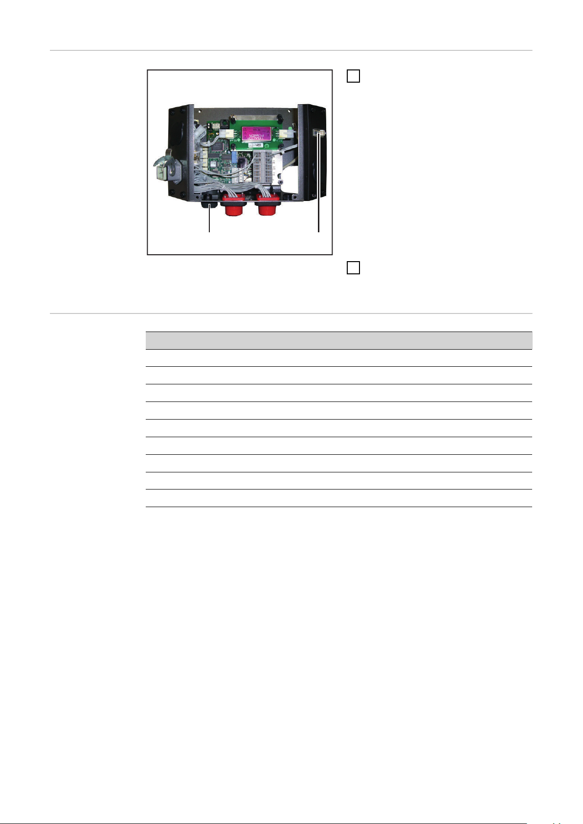
Raccorder l’in-
(2)(1)
terface AB DeviceNet Enterprise
Raccorder l’interface AB DeviceNet Enterprise
Raccorder la prise LocalNet du
1
faisceau de câbles intermédiaire au
connecteur LocalNet (1)
REMARQUE! Aussi longtemps que
l’interface robot est connectée au
LocalNet, le mode de service „Mode 2 temps“ reste automatiquement sélectionné (affichage : Mode
de service à 2 temps).
Vous trouverez des informations
plus détaillées concernant le mode
de soudage „Mode 2 temps spécial
pour interface robot“ dans le mode
d’emploi de la source de courant.
Raccorder le câble de données De-
2
viceNet Enterprise au connecteur
DeviceNet Enterprise (2).
Affectation pour
la connexion DeviceNet Enterprise (prise Submin 9 pôles)
Broche Affectation
1 Non utilisé
2 CAN_L
3 CAN_GND
4 Non utilisé
5 Non utilisé
6 GND
7 CAN_H
8 Non utilisé
9 CAN_V+
76
Page 77

Configurer des
AB DeviceNet Enterprise
signaux supplémentaires
La configuration des signaux d’entrée et de sortie supplémentaires s’effectue à
l’aide du programme Fronius „Module de service“ :
Start / Programme / Fronius Product Group / Servicemodul
-
Sélectionner l’entrée AB DeviceNet Enterprise
-
Cliquer sur le bouton Configuration
-
FR
Sélectionner „System settings“
-
Pour les signaux supplémentaires 105 - 112 sous „ROB I/O“, activer la case
-
de contrôle „Connect“
Pour les signaux supplémentaires 113 - 200 sous „Part number“, activer la
-
case de contrôle „Part number active“
IMPORTANT! Si seuls les signaux supplémentaires 105 - 112 doivent être utilisés
sans les signaux 113 - 200, l’option suivante est nécessaire au niveau de l’interface AB Device-Net Enterprise : „Kit d’installation Rob I/O“
Pour en savoir plus sur la configuration, consulter la notice EDS du module de
bus DeviceNet Anybus-S.
77
Page 78

Régler l’ID Mac
Le réglage de l’ID Mac se fait au niveau
du commutateur de configuration
TCP/IP à l’aide du commutateur Dip 3
- 8.
sw. = commutateur Dip
TCP/IP-Konfigurationsschalter
Mac ID sw. 3 (MSB) sw. 4 sw. 5 sw. 6 sw. 7 sw. 8 (LSB)
0 OFF OFF OFF OFF OFF OFF
1 OFF OFF OFF OFF OFF ON
2 OFF OFF OFF OFF ON OFF
3 OFF OFF OFF OFF ON ON
Régler le taux de
bauds
... ... ... ... ... ... ...
62 ON ON ON ON ON OFF
63 ON ON ON ON ON ON
Le réglage du taux de bauds se fait au
niveau du commutateur de configuration TCP/IP à l’aide du commutateur Dip
1 - 2.
sw. = commutateur Dip
Débit binaire sw. 1 sw. 2
125 kBit/s OFF OFF
250 kBit/s OFF ON
500 kBit/s ON OFF
(réservé) ON ON
Sélecteur de configuration TCP/IP
78
Page 79

Diagnostic d'erreur, élimination des erreurs sur le
(2)
(3)
(1)
(8)
(4)
(7)
(5)
(6)
circuit imprimé UBST1
Voyants DEL
d’état de service
sur circuit imprimé UBST 1
FR
(1) DEL „+5 V“
(2) DEL „Traffic 1 - 4“
(3) DEL „L1 - L7“
(4) DEL „EXT“
DEL „+5 V“ (1) La DEL „+5 V“ (1) s’allume lorsque la tension d’alimentation interne ou externe
DEL „Traffic 1 4“ (2)
est raccordée. La DEL „+5 V“ indique que le système électronique du circuit imprimé fonctionne correctement.
DEL Affichage Signification Remède
Traffic X Éteint ou al-
lumé
Traffic X Clignote Communication sur Lo-
Pas de communication
sur le LocalNet Fronius
calNet Fronius active
(5) Cavalier „EXT“
(6) Cavalier „INT“
(7) DEL „INT“
(8) DEL „VCC“
Vérifier la tension d’alimentation;
Contrôler le câblage
-
79
Page 80

DEL „L1 - L7“ (3)
(a) (b) (c)
DEL Affichage Signification Remède
L1 Éteint / Cli-
gnote
Erreur produite dans le
module
Voir numéro d’erreur selon
tableau / service aprèsvente
L2 Allumé Communication sur Local-
-
Net Fronius active
L3 Clignote Ethernet-Stack envoie des
-
données
L6 Allumé Ethernet - Connexion phy-
-
sique établie
L7 Cignote Transmission de données
-
Ethernet active
DEL „L1“ allumée :
La description des erreurs et les affichages correspondants à l’écran au niveau de
la source de courant sont décrits dans la notice „Interface robot“
(42,0410,0616) :
chapitre „Signaux de sortie vers le robot“, section „Numéro d’erreur UBST“
La DEL „L1“ clignote - L’erreur est signalée par le code de clignotement :
(a) Clignotement rapide :
Démarrage du code d’erreur
(b) Première impulsion lente :
Type d’erreur
(c) Deuxième impulsion lente :
Localisation de l’erreur
Code
d’erreur
Explication
de l’erreur Description de l’erreur Remède
1 1 Taille de cadre Ethernet max.
dépassée
2 Type Mailbox incorrect -
4 Flux de données UDP trop faible
sur le port 15000
5 Flux de données UDP excessif -
6 Flux de données UDP trop faible
sur le port 15001
7 Port UDP incorrect -
8 Erreur lors de l’initialisation Stack -
9 Appel de fonction non valide -
Déconnecter et
reconnecter l’interface
-
-
DEL „EXT“ (4) La DEL „EXT“ (4) s’allume si la tension d’alimentation externe est sélectionnée à
l’aide du cavalier „EXT“ (5).
80
Page 81

Cavalier „EXT“
(5) / Cavalier
„INT“ (6)
DEL „INT“ (7) La DEL „INT“ (7) s’allume si la tension d’alimentation interne est sélectionnée à
DEL „VCC“ (8) La DEL „VCC“ (8) s’allume lorsque la tension d’alimentation interne ou externe
Le cavalier „EXT“ (5) et le cavalier „INT“ (6) servent à choisir entre la tension
d’alimentation interne et externe. Lors de la livraison, le cavalier se trouve sur
„Tension d’alimentation externe“.
l’aide du cavalier „INT“ (6).
est raccordée. La DEL „VCC“ indique que la tension d’alimentation + 24 V pour
les composants est correcte dans le sens externe du côté LocalNet.
FR
81
Page 82

Diagnostic d’erreur, élimination des erreurs sur le
(2)
(4)
(1)
(3)
module de bus DeviceNet Anybus-S
Voyants DEL sur
le module de bus
DeviceNet Anybus-S
(1) Réserve
(2) Statut du réseau
(3) État du module
(4) Réserve
Voyants DEL sur le module de bus DeviceNet
Anybus-S
DEL Affichage Signification
1 - Réservé pour d’autres applications
2 Éteint pas d’alimentation en courant / pas en ligne
S’allume en vert connexion OK, en ligne
(3) Éteint Pas d’alimentation en courant du module de bus
4 - Réservé pour d’autres applications
Clignote en vert En ligne, pas de connexion
S’allume en rouge Problème de connexion critique
Clignote en rouge Temps de connexion dépassé
DeviceNet Anybus-S
S’allume en vert Module de bus DeviceNet Anybus-S prêt à fonc-
tionner
Clignote en vert Quantité de données supérieure à la quantité con-
figurée
S’allume en rouge Panne importante
Clignote en rouge Panne mineure
82
Page 83

Voyant d’état
Anybus-S
Le voyant d’état Anybus-S est une DEL
placée sur la surface du module de bus
DeviceNet Anybus-S.
Les erreurs et états suivants sont indiqués par le voyant d’état Anybus-S :
Voyant d’état allumé en rouge
Erreur Interner ou fonctionnement en
mode bootloader
Voyant d’état clignote en rouge, 1 Hz
Erreur dans la mémoire de configuration RAM
Voyant d’état clignote en rouge, 2 Hz
Défaut ASIC ou FLASH
Voyant d’état Anybus-S sur le module de bus
Ethernet/IP Anybus-S
Voyant d’état clignote en rouge, 4 Hz
Défaut de DPRAM
Voyant d’état clignote en vert, 2 Hz
Module de bus non initialisé
Voyant d’état clignote en vert, 1 Hz
Module de bus initialisé, fonctionnement normal
FR
83
Page 84

Propriétés de la transmission de données et caractéristiques techniques
Propriétés de la
transmission de
données
Dispositif de
sécurité
Topologie du réseau Bus linéaire, fermeture de bus
aux deux extrémités (121 Ohm),
câbles de dérivation possibles
Médium câble blindé torsadé à 2x2 conducteurs,
le blindage doit être exécuté
Nombre max. de participants 64
Longueur de bus max., selon le taux
de bauds réglé
Connexion bus Open Style Connector 5-polig
Modes de service Bit Strobe, Polling, Cycling,
Bande passante de données de processus
Format de données de processus Intel
En cas d’absence de transmission de données, toutes les entrées et sorties sont
remises à zéro et la source de courant se trouve à l’état „Stop“. Après la reprise
de la transmission de données a lieu la reprise du processus par les signaux suivants :
Signal “Robot ready”
-
Signal „confirmer défaut sources“
-
104 Bit (configuration standard)
100 m à 500 ko/s
250 m à 250 ko/s
500 m à 125 ko/s
Change of State (COS)
Caractéristiques
techniques AB
DeviceNet Enterprise
Fichier EDS Electronic Data
Sheet
Alimentation électrique 24 V DC +/- 10% interne
Absorption de courant 400 mA typ.
Emplacement de montage face arrière des
sources de courant :
Classe de protection IP23
Interface de configuration par module de configuration
Un fichier EDS est attribué à chaque participant dans un réseau DeviceNet. Le fichier EDS contient toutes les informations concernant les participants. Le fichier
EDS est nécessaire pour la configuration du réseau et est disponible sur le site
de téléchargement de l’adresse Internet suivante :
http://www.anybus.de/products/devicenet/Techn. Dokumentation/Configuration
file
TPS 3200 / 4000 / 5000
TS 4000 / 5000
bus de terrain
84
Page 85

Description des signaux AB DeviceNet Enterprise
Généralités En fonction du mode de service sélectionné, l’interface AB DeviceNet Enterprise
peut transmettre des signaux d’entrée et de sortie très différents.
Modes de service
de la source de
courant
Aperçu Le chapitre „Description des signaux AB DeviceNet Enterprise“ se compose des
Mode de service E05 E04 E03
Soudage MIG/MAG Synergic standard 0 0 0
Soudage MIG/MAG Synergic pulsé 0 0 1
Mode Job 0 1 0
Sélection de paramètres internes 0 1 1
Soudage MIG/MAG manuel standard 1 0 0
CC / CV 1 0 1
Soudage TIG 1 1 0
CMT / Procédé spécial 1 1 1
sections suivantes :
Signaux d’entrée et de sortie pour soudage MIG/MAG Synergic standard/
-
Synergic pulsé et CMT
Signaux d’entrée et de sortie pour TIG
-
Signaux d’entrée et de sortie pour CC/CV
-
Signaux d’entrée et de sortie pour standard manuel
-
FR
85
Page 86

Signaux d'entrée et de sortie pour soudage
MIG/MAG Synergic standard/Synergic pulsé et
CMT
Signaux d’entrée
(du robot vers la
source de courant)
N° d’ordre Description du signal Plage Activité
E01 Soudage activé - High
E02 Robot prêt - High
E03 Modes de service Bit 0 - High
E04 Modes de service Bit 1 - High
E05 Modes de service Bit 2 - High
E06 Identification du maître Twin - High
E07 Non utilisé - -
E08 Non utilisé - -
E09 Gas Test - High
E10 Amenée de fil - High
E11 Retour de fil - High
E12 Valider la panne de source - High
E13 Recherche de position - High
E14 Soufflage torche - High
E15 Non utilisé - -
E16 Non utilisé - -
E17- E24 Numéro de job 0 - 99 -
E25 - E31 Numéro de programme 0 - 127 -
E32 Simulation du soudage - High
Avec RCU 5000i et en mode de service Mode tâche
E17- E31 Numéro de job 0 - 999 -
E32 Simulation du soudage - High
Valeur de consigne puissance 0 - 65535 (0 - 100
%)
E33-E40 Low Byte - -
E41-E48 High Byte - -
Correction de la longueur de
l’arc électrique, Valeur de consigne
0 - 65535 (-30 - +30%)-
-
86
Page 87

N° d’ordre Description du signal Plage Activité
E49-E56 Low Byte - -
E57-E64 High Byte - -
E65-E72 Correction arc pulsé ou dynami-
0 - 255 (-5 - +5 %) -
que 1), Valeur de consigne
E73-E80 Valeur de consigne Brûlure re-
tour
0 - 255 (-200 - +200
ms)
-
Vitesse de soudage 0 - 32767 (0-3276
-
cm/min)
E81 - E88 Non utilisé - -
E89 - E96 Non utilisé - -
E97 Synchro Puls disable - High
E98 SFI disable - High
E99 Correction arc pulsé ou dynami-
- High
que 1) disable
E100 Burn back disable - High
E101 Pleine puissance (0 - 30 m) - High
E102-104 Non utilisé - -
FR
Signaux d’entrée
supplémentaires
„Rob I/O“ (du
robot vers la
source de courant)
1)
En fonction du procédé sélectionné et du programme de soudage réglé,
différents paramètres sont indiqués :
Procédé Paramètres
Impulsion Correction de l’impulsion
Standard Correction arc dynamique
CMT Hotstart-time
Correction de l’impulsion
Cycles d’impulsions Hotstart
Correction boost
Correction arc dynamique
N° d’ordre Description du signal Plage Activité
E105 ROB I/O Output 1 - High
E106 ROB I/O Output 2 - High
E107-112 Non utilisé - -
87
Page 88

Signaux d’entrée
supplémentaires
„Numéro de
composant“ (du
robot vers la
source de courant)
N° d’ordre Description du signal Plage Activité
E113-120 N° de composant, Caractère 1 ASCII 32 - 254 -
E121-128 N° de composant, Caractère 2 ASCII 32 - 254 -
E129-136 N° de composant, Caractère 3 ASCII 32 - 254 -
E137-144 N° de composant, Caractère 4 ASCII 32 - 254 -
E145-152 N° de composant, Caractère 5 ASCII 32 - 254 -
E153-160 N° de composant, Caractère 6 ASCII 32 - 254 -
E161-168 N° de composant, Caractère 7 ASCII 32 - 254 -
E169-176 N° de composant, Caractère 8 ASCII 32 - 254 -
E177-184 N° de composant, Caractère 9 ASCII 32 - 254 -
E185-192 N° de composant, Caractère 10 ASCII 32 - 254 -
E193-200 N° de composant, Caractère 11 ASCII 32 - 254 -
Signaux de sortie (de la source
de courant vers
le robot)
N° d’ordre Description du signal Plage Activité
A01 Arc électrique stable - High
A02 Signal limite (uniquement en re-
lation avec RCU 5000 i)
A03 Processus actif - High
A04 Signal courant principal - High
A05 Protection collision torche - High
A06 Source de courant prête - High
A07 Communication prête - High
A08 Non utilisé - -
A09 - A16 Numéro d’erreur 0 - 255 -
A17 - A24 Non utilisé - -
A25 Contrôle collage - High
A26 Non utilisé - -
A27 Accès robot (uniquement en re-
lation avec RCU 5000 i)
A28 Fil disponible - High
- High
- High
88
A29 Durée dépassée court-circuit - High
A30 Données documentation prêtes
(uniquement avec RCU 5000 i)
A31 Non utilisé - -
A32 Puissance hors plage - -
Tension de soudage (Valeur réelle)
A33 - A40 Low Byte - -
- High
0 - 65535
(0 - 100 V)
-
Page 89

N° d’ordre Description du signal Plage Activité
A41 - A48 High Byte - -
Courant de soudage (Valeur
réelle)
0 - 65535
(0 - 1000 A)
-
A49 - A56 Low Byte - -
A57 - A64 High Byte - -
A65 - A72 Courant moteur (Valeur réelle) 0 - 255
-
(0 - 5 A)
A73 - A80 Non utilisé - -
Vitesse du fil (Valeur réelle) 0 - 65535
(-327,68 - +327,67
0 - vD
max
)
A81 - A88 Low Byte - -
A89 - A96 High Byte - -
A97 Non-respect d'une limite vD - High
A98 Limite inférieure dépassée vD - High
A99 Non-respect d'une limite
- High
Courant de soudage
FR
Signaux de sortie supplémentaires „Rob I/O“
(du robot vers la
source de courant)
A100 Limite inférieure dépassée
- High
Courant de soudage
A101 Non-respect d'une limite
- High
Tension de soudage
A102 Limite inférieure dépassée
- High
Tension de soudage
A103 Non-respect d'une limite
- High
Moteur principal
A104 Non-respect d'une limite
- High
Moteur PushPull
N° d’ordre Description du signal Plage Activité
A105 ROB I/O Input 1 - High
A106 ROB I/O Input 2 - High
A107 ROB I/O Input 3 - High
A108 ROB I/O Input 4 - High
A109-112 Non utilisé - -
89
Page 90

Signaux de sortie supplémentaires „Numéro
de composant“
(du robot vers la
source de courant)
N° d’ordre Description du signal Plage Activité
A113-120 Non utilisé - -
A121-128 Non utilisé - -
A129-136 Non utilisé - -
A137-144 Non utilisé - -
A145-152 Non utilisé - -
A153-160 Non utilisé - -
A161-168 Non utilisé - -
A169-176 Non utilisé - -
A177-184 Non utilisé - -
A185-192 Non utilisé - -
A193-200 Non utilisé - -
90
Page 91

Signaux d'entrée et de sortie pour TIG
Signaux d’entrée
TIG (du robot
vers la source de
courant)
N° d’ordre Description du signal Plage Activité
E01 Soudage activé - High
E02 Robot prêt - High
E03 Modes de service Bit 0 - High
E04 Modes de service Bit 1 - High
E05 Modes de service Bit 2 - High
E06 Identification du maître Twin - High
E07 Non utilisé - -
E08 Non utilisé - -
E09 Gas Test - High
E10 Amenée de fil - High
E11 Retour de fil - High
E12 Valider la panne de source - High
E13 Recherche de position - High
E14 KD disable - High
E15 Non utilisé - -
FR
E16 Non utilisé - -
E17- E24 Numéro de job 0 - 99 -
E25 DC/AC - High
E26 DC- / DC+ - High
E27 Formation de calottes - High
E28 Impulsions disable - High
E29 Sélection plage d’impulsion Bit 0 - High
E30 Sélection plage d’impulsion Bit 1 - High
E31 Sélection plage d’impulsion Bit 2 - High
E32 Simulation du soudage - High
Courant principal (valeur de consi-
gne)
E33 - E40 Low Byte - -
E41 - E48 High Byte - -
0 - 65535 (0 I
)
max
-
Paramètre externe (valeur de con-
signe)
0 - 65535
91
Page 92

N° d’ordre Description du signal Plage Activité
E49 - E56 Low Byte - -
E57 - E64 High Byte - -
Signaux d’entrée
supplémentaires
„Rob I/O“ (du
robot vers la
source de courant)
E65 - E72 Courant de base (valeur de consi-
0 - 255 (0 - 100 %) -
gne)
E73 - E80 Duty Cycle (valeur de consigne) 0 - 255 (10 - 90 %) -
Vitesse du fil Fd.1 (valeur de con-
signe)
0 - 65535 (0 vD
)
max
-
E81 - E88 Low Byte - -
E89 - E96 High Byte - -
E97 - E98 Non utilisé - -
E99 Courant de base disable - High
E100 Duty Cycle disable - High
E101-104 Non utilisé - -
N° d’ordre Description du signal Plage Activité
E105 ROB I/O Output 1 - High
E106 ROB I/O Output 2 - High
E107-112 Non utilisé - -
Signaux d’entrée
supplémentaires
„Numéro de
composant“ (du
robot vers la
source de courant)
N° d’ordre Description du signal Plage Activité
E113-120 N° de composant, Caractère 1 ASCII 32 - 254 -
E121-128 N° de composant, Caractère 2 ASCII 32 - 254 -
E129-136 N° de composant, Caractère 3 ASCII 32 - 254 -
E137-144 N° de composant, Caractère 4 ASCII 32 - 254 -
E145-152 N° de composant, Caractère 5 ASCII 32 - 254 -
E153-160 N° de composant, Caractère 6 ASCII 32 - 254 -
E161-168 N° de composant, Caractère 7 ASCII 32 - 254 -
E169-176 N° de composant, Caractère 8 ASCII 32 - 254 -
E177-184 N° de composant, Caractère 9 ASCII 32 - 254 -
E185-192 N° de composant, Caractère 10 ASCII 32 - 254 -
E193-200 N° de composant, Caractère 11 ASCII 32 - 254 -
92
Page 93

Réglage de la
plage d'impulsion TIG
Sélection de la plage E31 E30 E29
Régler la plage d'impulsion au niveau de la source de courant
0 0 0
Signaux de sortie (de la source
de courant vers
le robot)
Plage de réglage impulsion désactivée
0,2 - 2 Hz 0 1 0
2 - 20 Hz 0 1 1
20 - 200 Hz 1 0 0
200 - 2000 Hz 1 0 1
N° d’ordre Description du signal Plage Activité
A01 Arc électrique stable - High
A02 Non utilisé - -
A03 Processus actif - High
A04 Signal courant principal - High
A05 Protection collision torche - High
A06 Source de courant prête - High
A07 Communication prête - High
0 0 1
FR
A08 Réserve - -
A09 - A16 Numéro d’erreur 0 - 255 -
A17 - A24 Non utilisé - -
A25 Non utilisé - -
A26 Haute fréquence active - High
A27 Non utilisé - -
A28 Fil disponible - High
A29 Non utilisé - -
A30 Non utilisé - -
A31 Puls High - High
A32 Non utilisé - -
Tension de soudage (valeur réelle)
A33 - A40 Low Byte - -
A41 - A48 High Byte - -
0 - 65535
(0 - 100 V)
-
Courant de soudage (valeur
réelle)
A49 - A56 Low Byte - -
0 - 65535
(0 - 1000 A)
-
93
Page 94

N° d’ordre Description du signal Plage Activité
A57 - A64 High Byte - -
Signaux de sortie supplémentaires „Rob I/O“
(du robot vers la
source de courant)
A65 - A72 Courant moteur (valeur réelle) 0 - 255
-
(0 - 5 A)
A73 - A80 Longueur de l’arc électrique
0 - 255 -
(valeur réelle) (AVC)
Vitesse d’avance du fil (valeur
réelle)
0 - 65535
(0 - vD
max
)
A81 - A88 Low Byte - -
A89 - A96 High Byte - -
A97 - E104 Non utilisé - -
N° d’ordre Description du signal Plage Activité
A105 ROB I/O Input 1 - High
A106 ROB I/OIntput 2 - High
A107 ROB I/O Input 3 - High
A108 ROB I/O Input 4 - High
Signaux de sortie supplémentaires „Numéro
de composant“
(du robot vers la
source de courant)
A109-112 Non utilisé - -
N° d’ordre Description du signal Plage Activité
A113-120 Non utilisé - -
A121-128 Non utilisé - -
A129-136 Non utilisé - -
A137-144 Non utilisé - -
A145-152 Non utilisé - -
A153-160 Non utilisé - -
A161-168 Non utilisé - -
A169-176 Non utilisé - -
A177-184 Non utilisé - -
A185-192 Non utilisé - -
A193-200 Non utilisé - -
94
Page 95

Signaux d'entrée et de sortie pour CC/CV
Signaux d’entrée
(du robot vers la
source de courant)
N° d’ordre Description du signal Plage Activité
E01 Soudage activé - High
E02 Robot prêt - High
E03 Modes de service Bit 0 - High
E04 Modes de service Bit 1 - High
E05 Modes de service Bit 2 - High
E06 Identification du maître Twin - High
E07 Non utilisé - -
E08 Non utilisé - -
E09 Gas Test - High
E10 Amenée de fil - High
E11 Retour de fil - High
E12 Valider la panne de source - High
E13 Recherche de position - High
E14 Soufflage torche - High
E15 - E16 Non utilisé - -
FR
E17- E24 Numéro de job 0 - 99 -
E25 - E31 Non utilisé - -
E32 Simulation du soudage - High
Courant de soudage (valeur de
consigne)
E33-E40 Low Byte - -
E41-E48 High Byte - -
Vitesse du fil 0 - 65535 (-30 - +30%)-
E49-E56 Low Byte - -
E57-E64 High Byte - -
E65-E72 Tension de soudage 0 - 255 (-5 - +5 %) -
E73-E80 Non utilisé - -
0 - 65535 (0 - max.) -
E81 - E88 Low Byte - -
E89 - E96 High Byte - -
E97 - 104 Non utilisé - -
95
Page 96

Signaux d’entrée
supplémentaires
„Rob I/O“ (du
robot vers la
source de courant)
N° d’ordre Description du signal Plage Activité
E105 ROB I/O Output 1 - High
E106 ROB I/O Output 2 - High
E107-112 Non utilisé - -
Signaux d’entrée
supplémentaires
„Numéro de
composant“ (du
robot vers la
source de courant)
Signaux de sortie (de la source
de courant vers
le robot)
N° d’ordre Description du signal Plage Activité
E113-120 N° de composant, Caractère 1 ASCII 32 - 254 -
E121-128 N° de composant, Caractère 2 ASCII 32 - 254 -
E129-136 N° de composant, Caractère 3 ASCII 32 - 254 -
E137-144 N° de composant, Caractère 4 ASCII 32 - 254 -
E145-152 N° de composant, Caractère 5 ASCII 32 - 254 -
E153-160 N° de composant, Caractère 6 ASCII 32 - 254 -
E161-168 N° de composant, Caractère 7 ASCII 32 - 254 -
E169-176 N° de composant, Caractère 8 ASCII 32 - 254 -
E177-184 N° de composant, Caractère 9 ASCII 32 - 254 -
E185-192 N° de composant, Caractère 10 ASCII 32 - 254 -
E193-200 N° de composant, Caractère 11 ASCII 32 - 254 -
N° d’ordre Description du signal Plage Activité
A01 Arc électrique stable - High
A02 Signal limite (uniquement en re-
lation avec RCU 5000i)
- High
A03 Processus actif - High
A04 Signal courant principal - High
A05 Protection collision torche - High
A06 Source de courant prête - High
A07 Communication prête - High
A08 Non utilisé - -
A09 - A16 Numéro d’erreur 0 - 255 -
A17 - A24 Non utilisé - -
A25 Contrôle collage - High
A26 Non utilisé - -
A27 Accès robot (uniquement en re-
lation avec RCU 5000i)
A28 Fil disponible - High
A29 Durée dépassée court-circuit - High
- High
96
Page 97

N° d’ordre Description du signal Plage Activité
A30 Données documentation prêtes
- High
(uniquement avec RCU 5000i)
A31 Non utilisé - -
A32 Puissance hors plage - High
Tension de soudage (valeur réelle)
0 - 65535
(0 - 100 V)
-
A33 - A40 Low Byte - -
A41 - A48 High Byte - -
Courant de soudage (valeur
réelle)
0 - 65535
(0 - 1000 A)
-
A49 - A56 Low Byte - -
A57 - A64 High Byte - -
A65 - A72 Courant moteur (valeur réelle) 0 - 255
-
(0 - 5 A)
A73 - A80 Non utilisé - -
FR
Vitesse du fil (valeur réelle) 0 - 65535
(-327,68 - +327,67
0 - vD
max
)
A81 - A88 Low Byte - -
A89 - A96 High Byte - -
A97 Non-respect d'une limite vD - High
A98 Limite inférieure dépassée vD - High
A99 Non-respect d'une limite
- High
Courant de soudage
A100 Limite inférieure dépassée
- High
Courant de soudage
A101 Non-respect d'une limite
- High
Tension de soudage
A102 Limite inférieure dépassée
- High
Tension de soudage
A103 Non-respect d'une limite
- High
Moteur principal
A104 Non-respect d'une limite
- High
Moteur PushPull
97
Page 98

Signaux de sortie supplémentaires „Rob I/O“
(du robot vers la
source de courant)
N° d’ordre Description du signal Plage Activité
A105 ROB I/O Input 1 - High
A106 ROB I/O Input 2 - High
A107 ROB I/O Input 3 - High
A108 ROB I/O Input 4 - High
A109-112 Non utilisé - -
Signaux de sortie supplémentaires „Numéro
de composant“
(du robot vers la
source de courant)
N° d’ordre Description du signal Plage Activité
A113-120 Non utilisé - -
A121-128 Non utilisé - -
A129-136 Non utilisé - -
A137-144 Non utilisé - -
A145-152 Non utilisé - -
A153-160 Non utilisé - -
A161-168 Non utilisé - -
A169-176 Non utilisé - -
A177-184 Non utilisé - -
A185-192 Non utilisé - -
A193-200 Non utilisé - -
98
Page 99

Signaux d'entrée et de sortie pour standard manuel
Signaux d’entrée
(du robot vers la
source de courant)
N° d’ordre Description du signal Plage Activité
E01 Soudage activé - High
E02 Robot prêt - High
E03 Modes de service Bit 0 - High
E04 Modes de service Bit 1 - High
E05 Modes de service Bit 2 - High
E06 Identification du maître Twin - High
E07 Non utilisé - -
E08 Non utilisé - -
E09 Gas Test - High
E10 Amenée de fil - High
E11 Retour de fil - High
E12 Valider la panne de source - High
E13 Recherche de position - High
E14 Soufflage torche - High
E15 Non utilisé - -
FR
E16 Non utilisé - -
E17- E24 Non utilisé - -
E25 - E31 Numéro de programme 0 - 127 -
E32 Simulation du soudage - High
Vitesse du fil 0 - 65535 (-327,67 -
+327,67 m/min)
E33-E40 Low Byte - -
E41-E48 High Byte - -
Tension de soudage 0 - 65535 (0 - U
E49-E56 Low Byte - -
E57-E64 High Byte - -
E65-E72 Correction arc dynamique 0 - 255 (-5 - +5 %) -
max
-
) -
E73-E80 Brûlure retour (valeur de consi-
gne)
0 - 255 (-200 - +200
ms)
-
99
Page 100

N° d’ordre Description du signal Plage Activité
Non utilisé - -
E81 - E88 Low Byte - -
E89 - E96 High Byte - -
E97 Non utilisé - -
E98 Non utilisé - -
Signaux d’entrée
supplémentaires
„Rob I/O“ (du
robot vers la
source de courant)
Signaux d’entrée
supplémentaires
„Numéro de
composant“ (du
robot vers la
source de courant)
E99 Correction arc pulsé ou dynami-
que 1) disable
E100 Burn back disable - High
E101 Pleine puissance (0 - 30 m) - High
E102-104 Non utilisé - -
N° d’ordre Description du signal Plage Activité
E105 ROB I/O Output 1 - High
E106 ROB I/O Output 2 - High
E107-112 Non utilisé - -
N° d’ordre Description du signal Plage Activité
E113-120 N° de composant, Caractère 1 ASCII 32 - 254 -
E121-128 N° de composant, Caractère 2 ASCII 32 - 254 -
E129-136 N° de composant, Caractère 3 ASCII 32 - 254 -
E137-144 N° de composant, Caractère 4 ASCII 32 - 254 -
- High
100
E145-152 N° de composant, Caractère 5 ASCII 32 - 254 -
E153-160 N° de composant, Caractère 6 ASCII 32 - 254 -
E161-168 N° de composant, Caractère 7 ASCII 32 - 254 -
E169-176 N° de composant, Caractère 8 ASCII 32 - 254 -
E177-184 N° de composant, Caractère 9 ASCII 32 - 254 -
E185-192 N° de composant, Caractère 10 ASCII 32 - 254 -
E193-200 N° de composant, Caractère 11 ASCII 32 - 254 -
 Loading...