

Fronius Symo Series, 12.0-3 208-240, 10.0-3 480, 12.5-3 480, 15.0-3 480 Installation Instructions Manual
...Page 1
Fronius prints on elemental chlorine free paper (ECF) sourced from certified sustainable forests (FSC).
/ Perfect Charging / Perfect Welding / Solar Energy
Fronius Symo - Installation
10.0-3 208-240
12.0-3 208-240
10.0-3 480
12.5-3 480
15.0-3 480
15.0-3 208
17.5-3 480
20.0-3 480
22.7-3 480
24.0-3 480
Installation Instructions
Inverter for grid-connected photo-
EN-US
voltaic systems
42,0426,0202,EA 011-29072019
Page 2

2
Page 3

Contents
Location selection and installation position................................................................................................ 5
Safety Instructions Explanation............................................................................................................. 5
Safety.................................................................................................................................................... 5
Intended Use......................................................................................................................................... 6
Location Selection................................................................................................................................. 7
Installation position of the inverter ........................................................................................................ 8
General Location Selection................................................................................................................... 9
Example: Installation of several inverters ............................................................................................. 10
Do not ground the solar modules.......................................................................................................... 10
Power Line Communication (PLC) Transmitter .................................................................................... 10
Preparation 11
Attaching the Mounting Bracket ................................................................................................................. 13
Safety.................................................................................................................................................... 13
Selecting Dowels and Screws............................................................................................................... 13
Screw recommendation ........................................................................................................................ 13
Opening the Inverter ............................................................................................................................. 13
Installing the Mounting Bracket on a Wall............................................................................................. 14
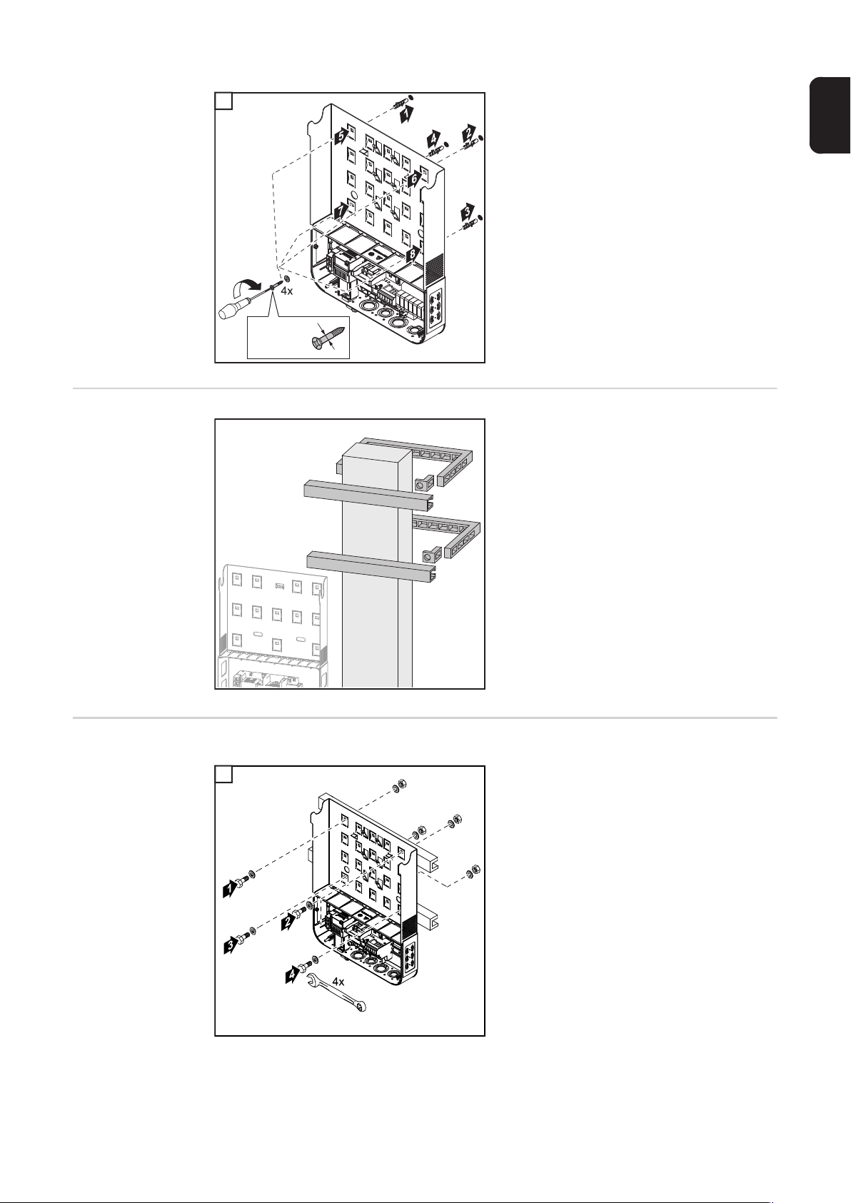
Installing the Mounting Bracket on a Mast or Beam ............................................................................. 15
Attaching the mounting bracket to a metal carrier ................................................................................ 15
Do not warp or deform the mounting bracket........................................................................................ 16
Knockouts .................................................................................................................................................. 17
Safety.................................................................................................................................................... 17
General ................................................................................................................................................. 17
Knocking or Drilling Out Knockouts ...................................................................................................... 18
EN-US
AC~ 21
Suitable Grids ............................................................................................................................................ 23
Connecting the inverter to the public grid (AC side) .................................................................................. 24
Safety.................................................................................................................................................... 24
Permitted Cables .................................................................................................................................. 25
Preparing Aluminum Cables for Connection......................................................................................... 26
Monitoring the grid ................................................................................................................................ 27
Fronius Symo 15.0-3 208 – ferrite ring ................................................................................................. 27
Connecting the Inverter to the Public Grid (AC).................................................................................... 27
Maximum AC fuse protection................................................................................................................ 29
Additional external AC and/or DC disconnect....................................................................................... 30
DC= 31
Notes on the Multi-MPP Tracker inverter................................................................................................... 33
Multi MPP Tracker – Inverter ................................................................................................................ 33
Connecting Solar Module Strings to the Inverter ....................................................................................... 34
Safety.................................................................................................................................................... 34
String Fuses.......................................................................................................................................... 35
Permitted Cables .................................................................................................................................. 36
General Information about Solar Modules ............................................................................................ 38
Connecting Aluminum Cables............................................................................................................... 38
Connecting Solar Module Strings to the Inverter .................................................................................. 39
Laying Solar.Net Cables 41
Data communication .................................................................................................................................. 43
Lay data communication cables............................................................................................................ 43
Installing Datamanager in the Inverter .................................................................................................. 44
Finally... 47
3
Page 4

Seal Conduits............................................................................................................................................. 49
Clipping the Inverter onto the Mounting Bracket........................................................................................ 50
Clipping the Inverter onto the Mounting Bracket................................................................................... 50
Using for the first time ................................................................................................................................ 53
Using the Inverter for the First Time ..................................................................................................... 53
Options 55
USB Stick as a Data Logger and for Updating Inverter Software .............................................................. 57
USB Flash Drive as a Data Logger....................................................................................................... 57
Data on the USB stick........................................................................................................................... 57
Data Amount and Memory Capacity ..................................................................................................... 58
Buffer Memory ...................................................................................................................................... 59
Suitable USB Thumb Drives ................................................................................................................. 59
USB Stick for Updating Inverter Software............................................................................................. 60
Removing the USB Stick....................................................................................................................... 60
Options....................................................................................................................................................... 61
Options.................................................................................................................................................. 61
OPTION 'ShadeCover'.......................................................................................................................... 61
Service and Maintenance 63
Notes on Maintenance ............................................................................................................................... 65
Maintenance ......................................................................................................................................... 65
Cleaning................................................................................................................................................ 65
4
Page 5
Location selection and installation position
EN-US
Safety Instructions Explanation
WARNING!
Indicates a potentially dangerous situation.
► Death or serious injury may result if appropriate precautions are not taken.
CAUTION!
Indicates a situation where damage or injury could occur.
► Minor injury or damage to property may result if appropriate precautions are not taken.
NOTE!
Indicates a possibility of flawed working results and possible damage to the equipment.
IMPORTANT!
Indicates tips for correct operation and other particularly useful information.
It does not indicate a harmful or dangerous situation.
Please pay special attention when one of the symbols from the "Safety rules" chapter appears in these instructions.
Safety
WARNING!
Danger from incorrect operation and work that is not carried out properly.
This can result in severe personal injury and damage to property.
► Only qualified staff are authorized to commission the inverter and only within the scope
of the respective technical regulations.
► Read the Installation Instructions and Operating Instructions before installation and
commissioning.
WARNING!
Danger from work that is not carried out properly.
This can result in damage to property and severe personal injury.
► The surge protection device should only be installed and connected by licensed elec-
tricians.
► Observe the safety rules!
► Prior to all installation and connection work, disconnect the AC and DC supply to the
inverter.
Fire Prevention
5
Page 6
CAUTION!
Danger due to faulty or incorrect installation.
This may result in damage to inverters and other current-carrying parts of a photovoltaic system.
Faulty or improper installation may cause overheating
of cables and terminals as well as the formation of arcs.
This could cause thermal damage, which in turn may
lead to fires.
Please note the following when connecting the AC and
3
DC cables:
► Securely tighten all terminals using the proper
torque listed in the Operating Instructions
► Securely tighten all grounding terminals (PE/GND)
2
2.5 Nm
1
using the proper torque listed in the Operating In-
structions, even for free grounding terminals
► Do not overload cables
► Check cables for damage and correct wiring
► Follow all safety instructions, Operating Instructions, and any local connection regula-
tions
► Always secure the inverter to the mounting bracket with fixing screws using the torque
specified in the Operating Instructions.
► Only put the inverter into operation with the fixing screws securely tightened.
Notice! Fronius will not bear any costs for production downtimes, or for installations, etc.,
which may arise due to a detected electric arc and its consequences. Fronius accepts no
liability for fires which may break out despite integrated arc detection/interruption (e.g., due
to a parallel arc).
Notice! Before an inverter can be reset following a detected electric arc, check the entire
affected photovoltaic system for any damage.
The manufacturer's specifications for connection, installation, and operation must be observed. You must carefully follow all installation steps and make all connections in accordance with specifications and regulations to minimize any risk of danger.
The tightening torques for the respective terminals are listed in the Installation Instructions
for the devices.
Intended Use The inverter is designed exclusively to convert direct current from solar modules into alter-
nating current and feed this power into the public grid.
The following are deemed to be not in conformity with its intended purpose:
- Utilization for any other purpose, or in any other manner
- Alternations to the inverter are not expressly recommended by Fronius
- Installation of components that are not expressly recommended or sold by Fronius.
The manufacturer is not responsible for any damage resulting from improper use.
All warranty claims are considered void in such cases.
Proper use also means
- carefully reading and obeying the instructions and all the safety and danger notices in
the Operating and Installation Instructions
- compliance with the maintenance operations
- installation as specified in the Installation Instructions
When configuring the photovoltaic system, make sure that all components are operating
completely within their permitted operating range.
6
Page 7
All measures recommended by the solar module manufacturer for maintaining solar module properties must be followed.
Location Selection
Follow all grid operator regulations regarding grid power feed and connection methods.
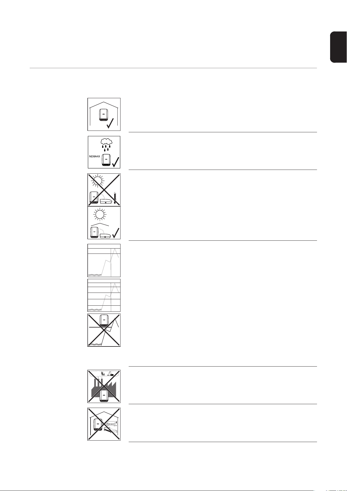
Please note the following criteria when choosing a location for the inverter:
The inverter is suitable for indoor installation.
The inverter is suitable for outdoor installation.
Because of its NEMA 4X protection class, the inverter is not susceptible
to hose water on any side and can also be operated in moist environments. However:
In order to keep inverter heating as low as possible, do not expose the
inverter to direct sunlight. The inverter should be installed in a protected
location, e.g., near the solar modules or under an overhanging roof.
EN-US
10.0-3 - 12.0-3 208-240
ft. (m)
0 - 11154 ft.
(0 - 3400 m)
10.0-3 - 24.0-3 480
ft. (m)
> 9842 - 11154 ft.
(> 3000 - 3400 m)
> 8202 - 9842 ft.
(> 2500 - 3000 m)
> 6561 - 8202 ft.
(> 2000 - 2500 m)
0 - 6561 ft.
(0 - 2000 m)
> 11154 ft.
> 3400 m
NH
3
U
DC max
600 V
U
DC max
850 V
900 V
950 V
1000 V
IMPORTANT! The inverter must not be installed or operated above an
altitude of 11,154 ft. (3400 m).
The maximum permissible DC voltage of the inverter depends on the altitude.
U
at an altitude of:
DCmax
Symo 10.0-3 – 12.0-3 208–240
0 to 11,154 ft ( 0 to 3400 m). = 600 V
Symo 10.0-3 – 24.0-3 480
0 to 6561 ft ( 0 to 2000 m). = 1000 V
6531 to 8202 ft (2000 to 2500 m). = 950 V
8202 to 9842 ft (2500 to 3000 m). = 900 V
9842 to 11,154 ft (3000 to 3400 m). = 850 V
The output power reduces when the device temperature is too high, and
this may occur earlier than normal at increased altitudes.
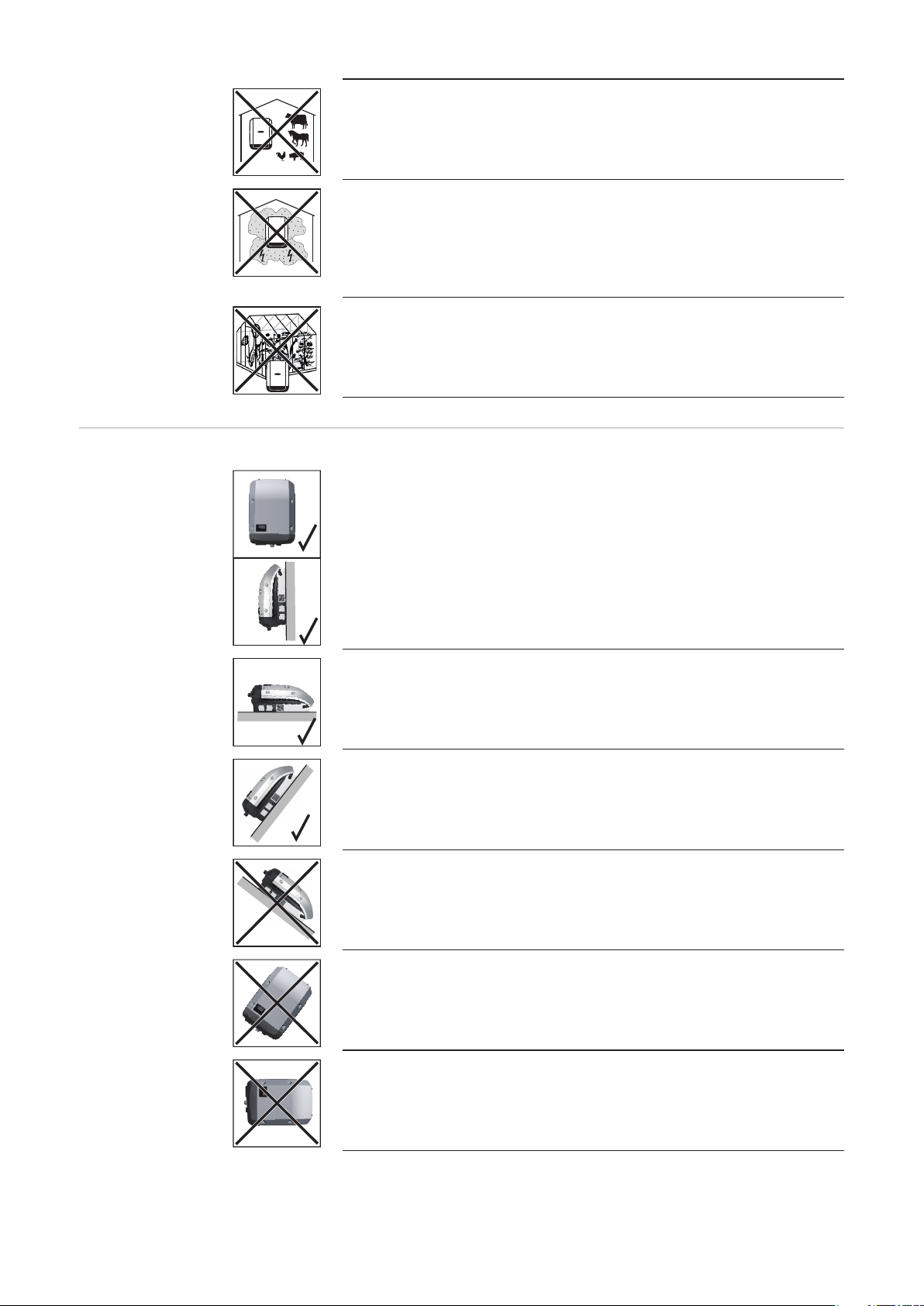
Do not install the inverter:
- where it may be exposed to ammonia, corrosive gases, acids, or
salts
(e.g., fertilizer storage areas, vent openings for livestock stables,
chemical plants, tanneries)
During certain operating phases the inverter may produce a slight noise.
For this reason, it should not be installed in an occupied living area.
7
Page 8
Installation position of the inverter
Do not install the inverter in:
- areas where there is an increased risk of accidents from farm animals (horses, cattle, sheep, pigs, etc.)
- Stables or adjoining areas
- storage areas for hay, straw, chaff, animal feed, fertilizers, etc.
The inverter is designed to be dustproof in principle. However, in areas
of high dust accumulation, the cooling surfaces can become dusty, which
can impair the thermal performance. In this case, the dust must be removed regularly. We therefore recommend that installation is not carried
out in areas and environments with high dust accumulation (e.g., iron filings) as this can cause damage to the inverter.
Do not install the inverter in:
- Greenhouses
- Storage or processing areas for fruit, vegetables, or viticulture products
- Areas used in the preparation of grain, green fodder, or animal feeds
The inverter is suitable for vertical installation on a vertical wall or column.
The inverter is suitable for a horizontal installation position.
The inverter is suitable for installation on a sloping surface.
Do not install the inverter on a sloping surface with the connections upwards.
Do not install the inverter in a sloping position on a vertical wall or column.
Do not install the inverter in a horizontal position on a vertical wall or column.
8
Page 9
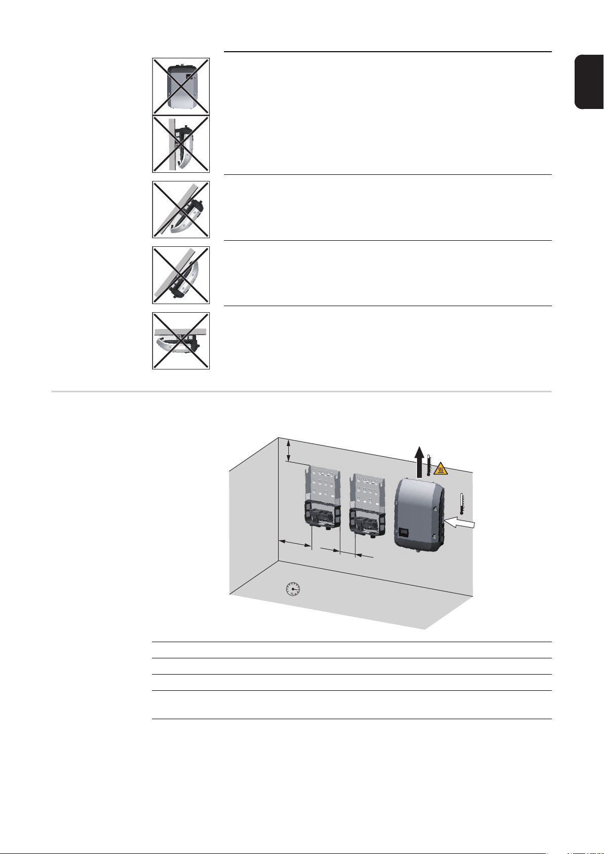
Do not install the inverter with the connections upwards on a vertical wall
or column.
Do not install the inverter overhanging with the connections upwards.
Do not install the inverter overhanging with the connections downwards.
Do not install the inverter on the ceiling.
EN-US
General Location
Selection
Please note the following criteria when choosing a location for the inverter:
8 in.
200 mm
4 in.
100 mm
4 in.
100 mm
-40 °F - +140 °F
-40 °C - +60 °C
0 - 100 %
Only install on a solid, non-flammable surface
Max. ambient temperatures: -40 °F/+140 °F (-40 °C/+60 °C)
Relative humidity: 0–100%
The air flow direction within the inverter is from right to top (cold air intake on the right, hot
air outflow at the top). The waste air may reach a temperature of up to 70 °C.
9
Page 10
When installing the inverter in a switch cabinet or similar closed environment, it is necessary to make sure that the hot air that develops will be dissipated by forced-air ventilation
If you wish to install the inverter on the outer walls of cattle stables, it is important to keep
a minimum clearance of 2 m between all sides of the inverter and air vents and other
openings.
The place of installation should not be exposed to ammonia, corrosive gases, salts, or
acids.
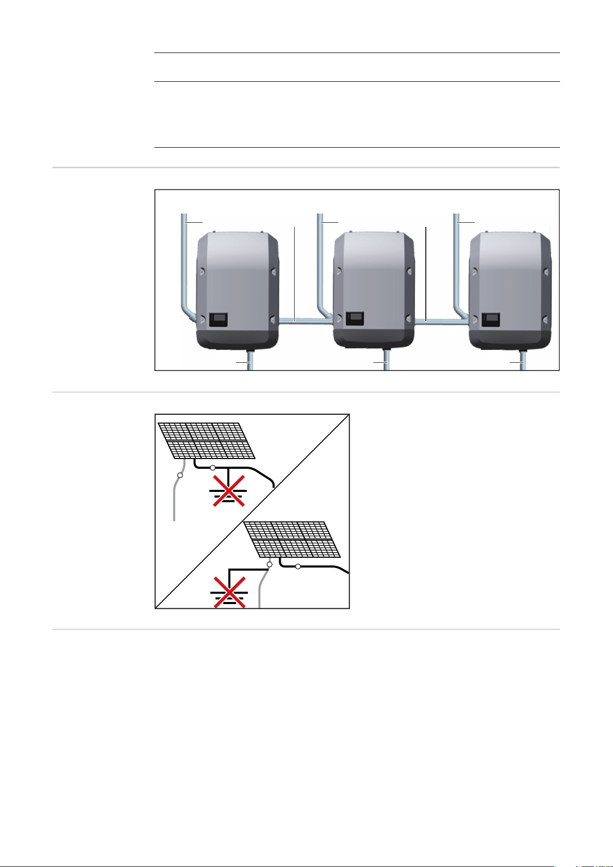
Example: Installation of several inverters
Do not ground the
solar modules.
Installation example of several inverters
DC = DC = DC =
AC ~ AC ~ AC ~
DATCOM DATCOM
The inverter is designed exclusively for
connection to and use with non-grounded
solar modules. The solar modules must not
be grounded at either the positive or nega-
+
-
tive pole.
Power Line Communication (PLC)
Transmitter
10
+
-
This inverter is equipped with a Power Line Communication (PLC) Transmitter on the DC
side.
The purpose is to provide Rapid Shutdown acc. to NEC Edition 2017 Art. 690.12. The PLC
is implemented according to the Specification "Communication Signal for Rapid Shutdown
- SunSpec Interoperability Specification". Details can be found at www.sunspec.org
To ensure compliance with all regulations applicable in your country and to provide best
reception at the receivers, please follow the recommendations below:
- Keep distance between DC+ and DC- Conductors as close as possible
- Avoid cable loops of excessive cables (coiling).
- Use metallic raceways where possible
- Do not run DC cables from different inverters in the same raceway or cable tray.
Page 11

Preparation
Page 12

Page 13

Attaching the Mounting Bracket
EN-US
Safety
WARNING!
Danger of residual voltage from capacitors.
An electric shock can be fatal.
► Wait until the capacitors have discharged. Discharge takes 5 minutes.
CAUTION!
Danger due to soiling or water on the terminals and contacts in the connection area.
This may result in damage to the inverter.
► When drilling, make sure that terminals and contacts in the connection area do not be-
come soiled or wet.
► The mounting bracket without integrated inverter does not correspond to the degree of
protection according to the data sheet. For this reason do not leave the mounting
bracket exposed to environmental influences without the inserted inverter.
► Protect the mounting bracket from soiling and moisture during installation.
NOTE!
Protection class NEMA4X is only ensured when the inverter is mounted and firmly
screwed into the mounting bracket.
The mounting bracket without inverter and ventilation channel has no NEMA protection.
Selecting Dowels
and Screws
Screw recommendation
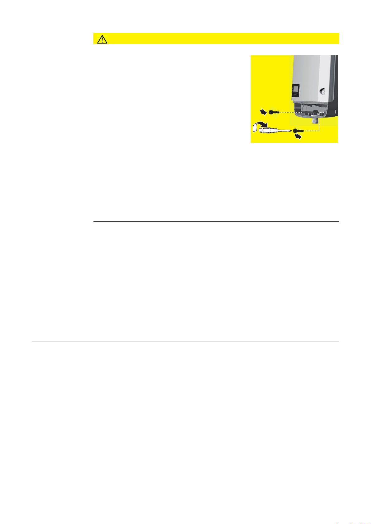
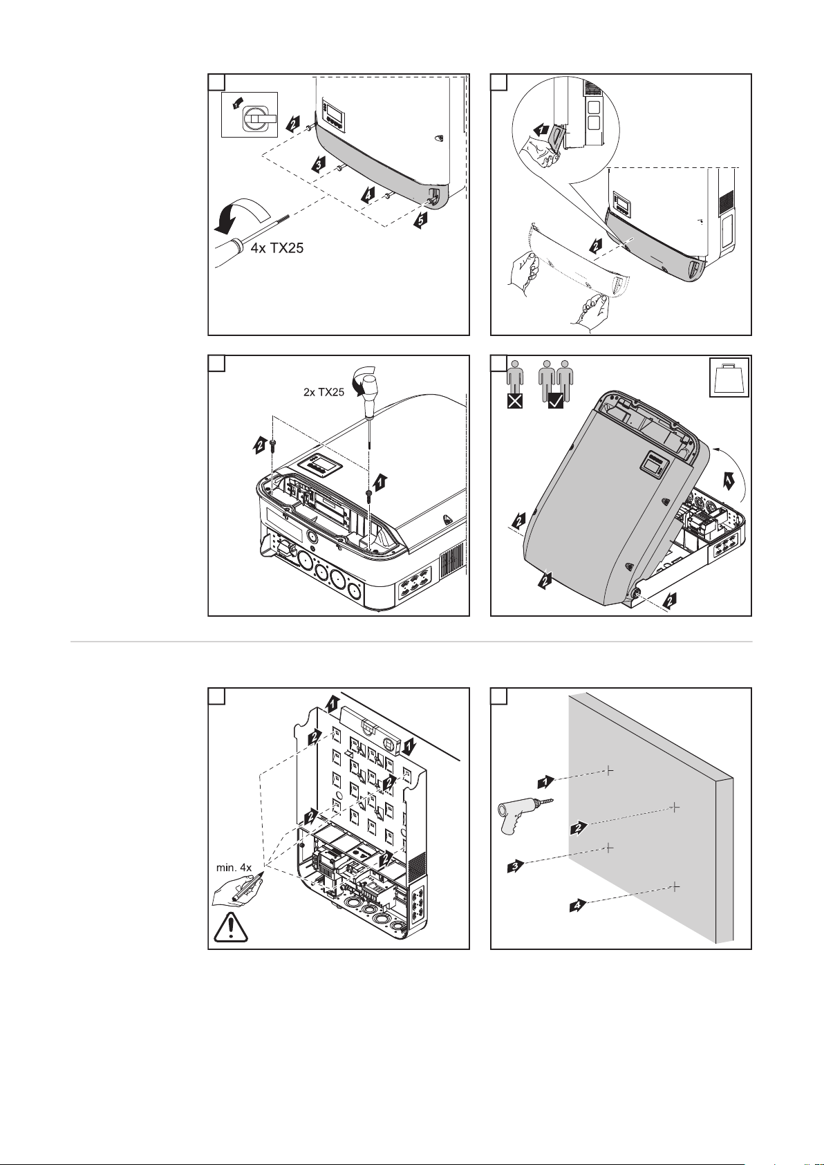
Opening the Inverter
Important! Depending on the surface, different mounting materials may be required for in-
stalling the mounting bracket. These mounting materials are not part of the scope of delivery for the inverter. The installer is responsible for selecting the proper mounting materials.
For the installation of the inverter we recommend steel or aluminum screws with a diameter
of 0.2–0.3 in. (6–8 mm).
WARNING!
Danger due to inadequate ground conductor connection.
This can result in severe personal injury and damage to property.
► The housing screws provide an adequate ground conductor connection for grounding
the housing and should not be replaced under any circumstances by other screws that
do not provide a reliable ground conductor connection.
13
Page 14
1 2
1
ON
OFF
Lock
3 4
3
2
4
lb
Installing the
Mounting Bracket
on a Wall
The mounting bracket must be secured in at least four places.
1 2
1
2
NO NEMA
ENCLOSURE TYPE
14
Page 15
3
3
EN-US
Al / St
0.2 - 0.3 in.
(6 - 8 mm)
Installing the
Mounting Bracket
on a Mast or
Beam
Attaching the
mounting bracket to a metal carrier
For installation of the inverter on a mast or
beam, Fronius recommends using the "Pole clamp" (order no. SZ 2584.000) mast
mounting kit from Rittal GmbH.
The kit can be used to mount the inverter on
round or rectangular masts with the following diameters: from 40 to 190 mm
(round mast), from 50 to 150 mm (rectangular mast)
The mounting bracket must be secured in at least four places.
1
1
15
Page 16
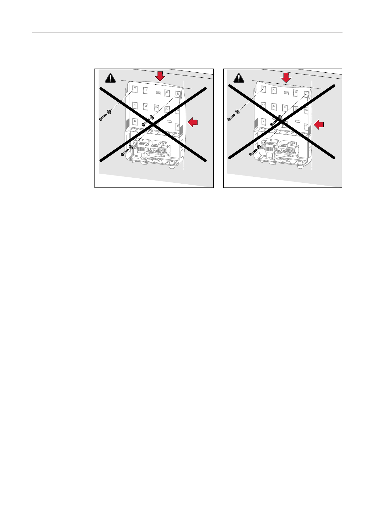
Do not warp or
deform the
mounting bracket
Notice! When attaching the mounting bracket to the wall or to a column, make sure that
the mounting bracket is not warped or deformed.
16
Page 17

Knockouts
EN-US
Safety
General
NOTE!
When using the cable inlets at the back, take care to seal them according to protection class NEMA4X before operating outdoors.
NOTE!
When installing outdoors, only use waterproof conduit fittings and conduits.
Conduit fittings and conduits are not part of the scope of supply for the inverter.
1/2 in. ... DATCOM
*
*
*
*
3/4 in. - 1 1/4 in. ... AC ~ / DC =
Conduit size
*
1/2 in. / 3/4 in. / 1 in.
Conduit size
**
1/2 in. / 3/4 in. / 1 in. / 1 1/4 in.
*
METAL EMPOSSING
Remove parts fallen
into the connection
area before hanging the
inverter to the wall
bracket!
** **
1 1/4 in. 1 1/4 in. 1 in. 1 in.
*
METAL EMPOSSING
Remove parts fallen
into the connection area before
hanging the inverter to the wall
bracket!
** **
The wall bracket contains several knockouts of different sizes. When knocked out, the
openings are used for the inputs of various wires.
1/2 in. for data communication cable (DATCOM)
3/4 in. - 1 1/4 in. for AC and DC cables
* A grounding electrode terminal (GET) may be required depending on local regula-
tions.
The cable for the grounding electrode terminal can be fed through the designated
opening on the underside of the wall bracket.
IMPORTANT! The knockouts on the rear of the wall bracket are made of metal.
17
Page 18
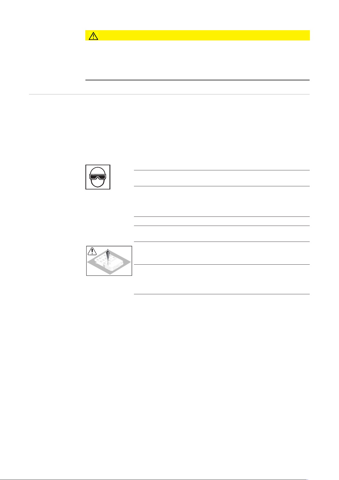
CAUTION!
Danger of short circuit from loose metal parts from knockouts.
Loose metal parts in the inverter may cause short circuits when the inverter is powered up.
When removing knockouts, make sure that
► no loose metal parts fall into the connection area of the inverter,
► any metal pieces that do fall into the connection area are removed immediately.
Knocking or Drilling Out Knockouts
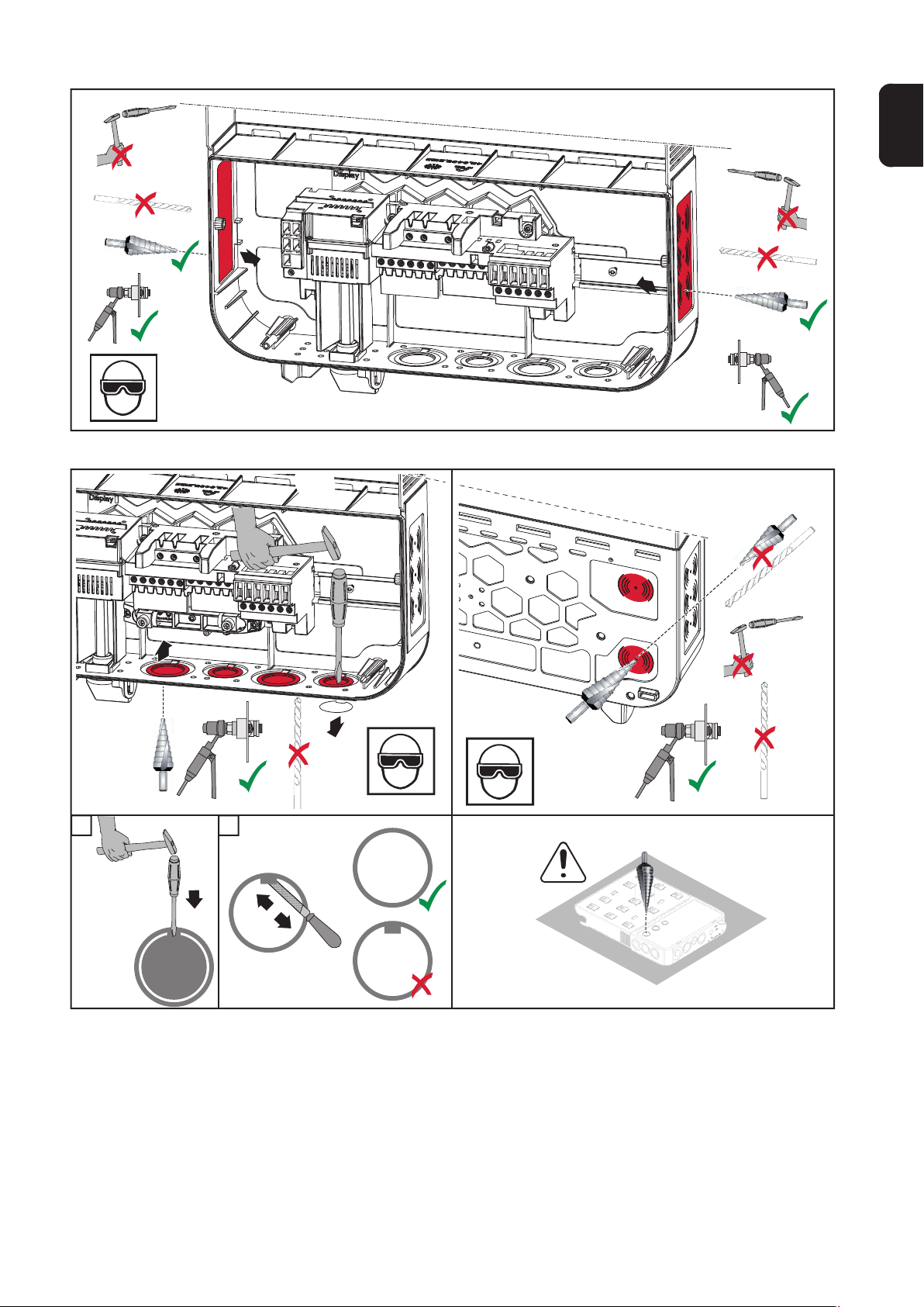
IMPORTANT! The knockouts on the underside of the mounting bracket may be knocked
out using a hammer or screwdriver, drilled out using a step drill, or opened using a hole
punch. The side knockouts and the knockouts at the back may only be drilled out with a
step drill or opened with a hole punch.
IMPORTANT! You should only remove the minimum number of knockouts required for the
available cables.
Use suitable eye protection when knocking/drilling out the knockouts.
Only knock out knockouts using a hammer or screwdriver from the inside outwards.
Only use suitable step drills to drill out the knockouts.
Do not use spiral drills for drilling out!
Only drill out knockouts using a step drill from the outside inwards.
When drilling out using a step drill, ensure that the inside of device
(e.g. connection block) is not damaged.
*
When drilling out the knockouts at the back, place the mounting
bracket on an even surface with the back upwards so that shavings
and pieces of metal can fall out of the mounting bracket.
Attach appropriate conduits to all knocked/drilled out knockouts.
In the event of installation outside, only use watertight conduits and
conduit fittings.
Conduits and conduit fittings are not included with the inverter.
If necessary, deburr the number of knockouts required with a suitable
tool.
18
Page 19
EN-US
1 2
*
*
19
Page 20

20
Page 21

AC~
Page 22

Page 23

Suitable Grids
Delta
Setup:
208
240
220
BR
50 Hz
MG 3P
MG 1P
WYE
Setup:
208 N
220 N
BR N
50 HN
HI2
480 N
440 N
50 HN
MG 3N
MG 2N
MG 5N
MG 6
No neutral conductor
Nominal voltage:
208 V
240 V
220 V
220 V
50 Hz 208–240 V
Microgrid 208 V
Microgrid 240 V
Neutral conductor required
Nominal voltage:
208 V
220 V
220 V
50 Hz 208–240 V
208 V
480 V
440 V
50 Hz 415 V
Microgrid 208 V
Microgrid 50 Hz 208–240 V
Microgrid 50 Hz 480 V
Microgrid 480 V
Appropriate inverter:
Symo 10.0-3 208–240 /
12.0-3 208–240 / 15.0-3
208
Appropriate inverter:
Symo 10.0-3 208–240 /
12.0-3 208–240 / 15.0-3
208
Symo 10.0-3 480 / 12.5-3
480 / 15.0-3 480 / 17.5-3
480 / 20.0-3 480 / 22.7-3
480 / 24.0-3 480
L1
EN-US
=
~
L3
=
L2-L3
120°
L1
N
L2
~
L3
L2-L3
120°
L2
CAL3
HI3
Hi-Leg Delta
Setup:
240 N
50 HN
MG 1N
MG 2N
HI1
480 V
480 V
Neutral conductor required
Nominal voltage:
240 V
50 Hz 208–240 V
Microgrid 240 V
Microgrid 50 Hz 208–240 V
208 V
Appropriate inverter:
Symo 10.0-3 208–240 /
12.0-3 208–240
L3
90°
=
L2-L3
90°
L3-L1
~
L2
L1-NL2-N
N
180°
L1
23
Page 24

Connecting the inverter to the public grid (AC side)
Safety
WARNING!
Danger from grid voltage and DC voltage from solar modules that are exposed to
light.
An electric shock can be fatal.
► Prior to all connection work, disconnect the AC and DC supply to the inverter.
► The DC main switch is used only to switch off power to the power stage set. When the
DC main switch is turned off, the connection area is still energized.
► Maintenance and service work on the inverter power stage set should only be carried
out by Fronius-trained service technicians.
► All maintenance and service work should only be carried out when the inverter and the
mounting bracket have been disconnected from each other.
► The inverter must only be disconnected from the mounting bracket after being discon-
nected from the mains power.
► Only an authorized electrician is permitted to connect this inverter to the public grid.
WARNING!
Inadequately sized electrical components can cause serious injury and damage to
property.
An electric shock can be fatal.
► All electrical connections must be made in accordance with the national standard (e.g.,
for the US National Electrical Code, ANSI/NFPA 70) and any other regulations appli-
cable to the installation site.
► Use min. 194 °F (90 °C) copper wire for all grounding wires (see NEC table 250.122).
► For all AC/DC wires, use a minimum of 167 °F (75 °C).
► Voltage drop and other considerations, such as improving power quality, may mean
larger cable cross sections need to be used.
WARNING!
Danger from work that is not carried out properly
This can result in damage to property and severe personal injury.
► The surge protection device should only be installed and connected by licensed elec-
tricians.
► Observe the safety rules!
► Prior to all installation and connection work, disconnect the AC and DC supply to the
inverter.
CAUTION!
Danger due to improperly connected terminals.
This may result in thermal damage to the inverter, which in turn may lead to fires.
► When connecting the AC and DC cables, make sure that all terminals are tightened se-
curely using the proper torque.
24
Page 25

NOTE!
When connecting aluminum cables:
► Follow all national and international guidelines regarding the connection of aluminum
cables.
► Follow the instructions of the cable manufacturer, especially the note about whether an
annual check to ensure that the cables are firmly attached should be performed.
NOTE!
Form a min. 4 in. (100 mm) cable loop with all cables.
NOTE!
To ensure that the inverter operates without any problems:
► Make sure that the grid's neutral conductor is grounded. For insulated networks (with-
out grounding), this is not the case, and operation of the inverter is not possible.
► A neutral conductor is required for measurement purposes when operating the invert-
er. The neutral conductor must have a current carrying capacity of at least 1 A.
EN-US
Permitted Cables AC cables with the following design can be connected to the AC terminals of the inverter:
Cu / Al Cu
- Copper (Cu) or aluminum (Al): round, solid
- Copper: round, stranded, up to conductor class 4
AC & DC = copper cables (Cu)
The following wire combinations can be used for wiring.
Select a sufficiently large cable cross-section based on the actual device output!
AWG
round
4
6
8
10
12
14
16
AWG
strand
ed
2)
2)
2)
2)
2)
2)
3)
6/6
8
10
12
14
16
4)
1)
8/101)8/121)8/14
1)
1)
1)
3)
AWG
stranded/round
AWG
round/round
stranded/stranded
AWG
6/122)6/142)6/16
1)
10/101)10/121)10/14
8/12
2)
1)
8/102)8/121)8/141)8/16
10/101)10/121)10/141)10/16
12/101)12/121)12/141)12/161)12/101)12/121)12/141)12/16
14/101)14/121)14/141)14/161)14/101)14/121)14/141)14/16
16/141)16/161)16/103)16/121)16/141)16/16
3)
3)
3)
1)
1)
1)
AC & DC = aluminum cables (Al)
The following wire combinations can be used for wiring.
Select a sufficiently large cable cross-section based on the actual device output!
AWG
round
4
6
8
AWG
strand
ed
2)
2)
2)
6
8
4)
2)
8/102)8/122)8/14
AWG
stranded/round
AWG
round/round
2)
8/12
2)
AWG
stranded/stranded
6/122)6/142)6/16
8/102)8/122)8/142)8/16
5)
5)
25
Page 26
AC & DC = aluminum cables (Al)
The following wire combinations can be used for wiring.
Select a sufficiently large cable cross-section based on the actual device output!
2)
2)
2)
5)
AWG
strand
ed
2)
10
2)
12
2)
14
5)
16
AWG
stranded/round
AWG
round/round
10/102)10/122)10/14
12/102)12/122)12/14
2)
2)
10/102)10/122)10/142)10/16
12/102)12/122)12/142)12/16
14/102)14/122)14/142)14/162)14/102)14/122)14/142)14/16
16/142)16/162)16/105)16/122)16/142)16/16
AWG
round
10
12
14
16
AWG
stranded/stranded
5)
2)
2)
2)
1)
2)
3)
4)
5)
tested and inspected as per UL
not inspected as per UL; connection possible
with ferrules only
use stranded PV (ZKLA) or 2-wire
not inspected as per UL; connection possible; AWG 16 with ferrules only
Minimum AWG as per NEC
Copper (Cu)/aluminum (Al)
Copper (Cu)/aluminum (Al)
Copper (Cu)/aluminum (Al)
208 V
220 V
240 V
440 V
480 V
440 V
480 V
10.0-3 208-240 12.0-3 208-240 15.0-3 208
AWG 10/AWG 10 AWG 10/AWG 8 AWG 8/AWG 6
AC
AWG 10/AWG 10 AWG 10/AWG 8
AC
AWG 12/AWG 10 AWG 10/AWG 10
AC
10.0-3 480 12.5-3 480 15.0-3 480
AWG 14/AWG 12 AWG 14/AWG 12 AWG 14/AWG 12
AC
AWG 14/AWG 12 AWG 14/AWG 12 AWG 14/AWG 12
AC
17.5-3 480 20.0-3 480 22.7-3 480
AWG 12/AWG 10 AWG 10/AWG 10 AWG 10/AWG 8
AC
AWG 14/AWG 12 AWG 12/AWG 10 AWG 10/AWG 10
AC
Copper (Cu)/aluminum (Al) 480 V
Preparing Aluminum Cables for
Connection
The AC-side terminals are designed for connecting single-wire, round aluminum cables.
Due to the reaction of aluminum with air that creates a tough, non-conductive oxide layer
the following points must be considered when connecting aluminum cables:
- Reduced rated currents for aluminum cables
- The connection requirements listed below
Always follow the instructions of the cable manufacturer when using aluminum cables.
Take into account local specifications when configuring cable cross sections.
Connection Requirements:
Carefully clean off the oxide layer of the stripped end of the cable, e.g., using a knife
1
26
AWG 10/AWG 10
AC
24.0-3 480
Page 27

IMPORTANT! Do not use brushes, files, or sandpaper; aluminum particles may get stuck
and can transfer to other cables.
Monitoring the
grid
Fronius Symo
15.0-3 208 – ferrite ring
After removing the oxide layer of the cable end, rub in a neutral grease, e.g., acid-free
2
and alkali-free Vaseline
Then immediately connect it to the terminal
3
IMPORTANT!Repeat the steps above whenever the cable is disconnected and then reconnected.
The resistance in the leads to the AC-side connection terminals must be as low as possible
for optimal functioning of grid monitoring.
1
1
With Fronius Symo 15.0-3 208, the three
phases and neutral conductor must be fed
through a ferrite ring. The ferrite ring is included in the scope of delivery for the inverter.
The ground conductor (PE) must not be fed
through the ferrite ring.
EN-US
Connecting the
Inverter to the
Public Grid (AC)
Fronius Symo
15.0-3 208
Fronius Symo 15.0-3 208
NOTE!
To ensure a proper ground connection, all grounding terminals GND must be tightened with the specified torque during installation.
NOTE!
Form loops of at least 4 in. (102 mm) in the AC cables when connecting them to the
AC terminals.
IMPORTANT! The ground conductor GND of the AC cable must be laid so that it is discon-
nected last.
Measure the ground conductor GND longer, for example, and loop.
27
Page 28

1 2
PE
1
1
2
3
3
AC ~
PE
0.6 in. (15 mm)
§
OFF
?
PE
max. 80 A
IΔN ≥ 100 mA
RCD
GNDGND
Torque (Nm /
lbf.in.) → see
printing near
wire terminal
AC
~
YES
National Standards
Type A
If AC cables are laid over the shaft of the
DC main switch or across the DC main
switch connection block, the cables may be
damaged when the inverter is pivoted or the
inverter may not be able to be pivoted.
IMPORTANT! Do not lay AC cables over the shaft of the DC main switch or across the DC
main switch connection block!
28
Page 29

If excessively long AC or DC cables are laid
in loops in the connection area, fix the cables to the designated eyelets at the top and
bottom of the connection block using cable
ties.
EN-US
Maximum AC
fuse protection
Power circuit breaker
AC ~
max. 80 A
Inverter Phases AC power Maximum fuse protection
Fronius Symo 10.0-3 208-240 3+N 10,000 W C 80 A
Fronius Symo 12.0-3 208-240 3+N 12,000 W C 80 A
Fronius Symo 10.0-3 480 3+N 10,000 W C 80 A
Fronius Symo 12.5-3 480 3+N 12,500 W C 80 A
Fronius Symo 15.0-3 480 3+N 15,000 W C 80 A
Fronius Symo 15.0-3 208 3+N 15,000 W C 80 A
Fronius Symo 17.5-3 480 3+N 17,500 W C 80 A
Fronius Symo 20.0-3 480 3+N 20,000 W C 80 A
Fronius Symo 22.7-3 480 3+N 22,700 W C 80 A
Fronius Symo 24.0-3 480 3+N 24,000 W C 80 A
RCCB
§
National Standards
?
IΔN ≥ 100 mA
RCD
YES
Type A
29
Page 30

NOTE!
A residual current circuit breaker for the AC connecting cable may be required depending on local regulations, the grid operator, and other conditions.
A type A residual current circuit breaker with a trip current of at least 100 mA is generally
sufficient in this case. However, false alarms can be triggered for the residual current circuit
breaker type A in individual cases and depending on local conditions. For this reason, Fronius recommends that you use a residual current circuit breaker suitable for frequency converters.
Additional external AC and/or DC
disconnect
Depending on the installation, an additional external AC and/or DC disconnect may be required if the inverter is installed in a location not easily accessible to utility or fire personnel.
Contact your local authorities for additional information.
30
Page 31

DC=
Page 32

Page 33

Notes on the Multi-MPP Tracker inverter
DC
+1
DC
+2
DC-
42,0201,4479
42,0201,4480
EN-US
Multi MPP Tracker – Inverter
PV 1PV 1
PV 2
max 33 A to a single
DC terminal
DC+2
DC
1
+1 +2
+1
2
3123
DC
DC
+2
123456
BASIC
MPP TRACKER 2
OFF
10.0-3, 12.0-3 max. 43,5A
15.0-3,17.5-3,20.0-3 max 51A
DC+
42,0201,4479
DC-
42,0201,4480
PV 1
DC+1
DC-2
DC+1
PV 2
DC-1
DC-1
Connecting two solar module fields to a Multi MPP
Tracker inverter
Multi MPP Tracker inverters have two independent DC inputs (MPP Tracker). These
inputs can be connected to a number of different modules.
Each MPP Tracker has 3 DC+ terminals.
There are a total of six DC- terminals.
Connecting two–six strings in Multi MPP
Tracker mode:
Connect the strings separately to the two
MPP Tracker inputs (DC+1/DC+2). The
DC- terminals can be used as desired, since they are connected internally.
Set MPP TRACKER 2 to "ON" when starting for the first time (also subsequently
possible in the basic menu)
Single MPP Tracker mode on a Multi MPP
Tracker inverter:
If the inverter is being operated with an external string collection box, the DC connector kit (item numbers 42,0201,4479 and
42,0201,4480) must be used
Set MPP TRACKER 2 to "OFF" when starting for the first time (also subsequently
possible in the basic menu)
Connecting multiple combined solar module fields to a
line on a Multi MPP Tracker inverter
If the Multi MPP Tracker inverter is operated in Single MPP Tracker mode, the currents of the connected DC lines are
distributed evenly across both inputs.
33
Page 34

Connecting Solar Module Strings to the Inverter
Safety
WARNING!
Danger from grid voltage and DC voltage from solar modules that are exposed to
light.
An electric shock can be fatal.
► Prior to all connection work, disconnect the AC and DC supply to the inverter.
► The DC main switch is used only to switch off power to the power stage set. When the
DC main switch is turned off, the connection area is still energized.
► Maintenance and service work on the inverter power stage set should only be carried
out by Fronius-trained service technicians.
► All maintenance and service work should only be carried out when the inverter and the
mounting bracket have been disconnected from each other.
► The inverter must only be disconnected from the mounting bracket after being discon-
nected from the mains power.
► Only an authorized electrician is permitted to connect this inverter to the public grid.
WARNING!
Inadequately sized electrical components can cause serious injury and damage to
property.
An electric shock can be fatal.
► All electrical connections must be made in accordance with the national standard (e.g.,
for the US National Electrical Code, ANSI/NFPA 70) and any other regulations appli-
cable to the installation site.
► Use min. 194 °F (90 °C) copper wire for all grounding wires (see NEC table 250.122).
► For all AC/DC wires, use a minimum of 167 °F (75 °C).
► Voltage drop and other considerations, such as improving power quality, may mean
larger cable cross sections need to be used.
WARNING!
Danger from work that is not carried out properly
This can result in damage to property and severe personal injury.
► The surge protection device should only be installed and connected by licensed elec-
tricians.
► Observe the safety rules!
► Prior to all installation and connection work, disconnect the AC and DC supply to the
inverter.
CAUTION!
Danger due to improperly connected terminals.
This may result in thermal damage to the inverter, which in turn may lead to fires.
► When connecting the AC and DC cables, make sure that all terminals are tightened se-
curely using the proper torque.
34
Page 35
CAUTION!
Danger due to overloading on the inverter.
This may result in damage to the inverter.
► Observe the maximum current carrying capacity of the various power categories (see
Table A).
► Only connect a maximum of 33 A to each DC terminal.
► Connect the DC+ and DC- cables to the correct DC+ and DC- terminals on the inverter.
► Observe the maximum DC input voltage.
Table A
Power category Maximum current carrying
capacity
MPP1 / MPP2
10.0-3 208–240/12.0-3 208–240/10.0-3 480/12.5-3 480 25 A / 16.5 A
15.0-3 208 50 A
15.0-3 480/17.5-3 480/20.0-3 480/22.7-3 480/24.0-3 480 33 A / 25 A
NOTE!
Solar modules exposed to light supply current to the inverter.
EN-US
NOTE!
When using the cable inlets at the back, take care to seal them according to protection class NEMA4X before operating outdoors.
NOTE!
When connecting aluminum cables:
► follow all national and international guidelines regarding the connection of aluminum
cables
► follow the instructions of the cable manufacturer
► perform an annual check to ensure that the cables are firmly attached according to the
proper torque
NOTE!
When connecting DC cables, ensure the polarity is correct.
NOTE!
Form a min. 4 in. (100 mm) cable loop with all cables.
String Fuses Only applies to device type Fronius Symo 15.0-3 208 and device types Fronius Symo
15.0-3 480 / 20.0-3 480 / 22.7-3 480 / 24.0-3 480 with the "Ecofuse" option:
The use of string fuses in the Fronius Symo provides additional fuse protection for solar
modules.
The maximum short circuit current ISC, the maximum module backfeed current IR and the
specification of the maximum string fuse value in the module data sheet of the respective
35
Page 36

solar module are decisive factors in the protection of the solar module.
Do not remove cover!
Each Terminal: I
max
= 15 A
The maximum short circuit current ISC per terminal is 15 A.
The string fuse release current can be set to greater than 15 A if required. However, a release current of 20 A must not be exceeded.
If the inverter is being operated with an external string collection box, the DC connector kit
25 (item numbers 42,0201,4479 for DC+ and 42,0201,4480 for DC-) must be used. In this
case the solar modules are externally protected in the string collection box and the metal
bolts should be used in the inverter.
National regulations regarding fuse protection must be observed. The electrical engineer
carrying out the installation is responsible for the correct choice of string fuses.
CAUTION!
Danger due to faulty fuses.
This can result in fire.
► Only replace faulty fuses with new ones of the same rating.
The inverter is delivered with metal bolts as standard.
Option DC SPD
DC+ 2.1
DC+ 1.3
DC+ 1.2
DC+ 1.1
Permitted Cables AC cables with the following design can be connected to the AC terminals of the inverter:
Cu / Al Cu
Do not remove cover!
- Copper (Cu) or aluminum (Al): round, solid
- Copper: round, stranded, up to conductor class 4
DC+ 2.3
DC+ 2.2
DC- 1.2
DC- 1.1
Each Terminal: I
= 15 A
max
DC- 1.3
DC- 2.1
DC- 2.2
DC- 2.3
AC & DC = copper cables (Cu)
The following wire combinations can be used for wiring.
Select a sufficiently large cable cross-section based on the actual device output!
AWG
round
4
6
8
36
AWG
strand
ed
2)
2)
2)
6/6
8
4)
1)
stranded/round
8/101)8/121)8/14
AWG
1)
AWG
round/round
2)
8/12
AWG
stranded/stranded
6/122)6/142)6/16
8/102)8/121)8/141)8/16
3)
3)
Page 37

AC & DC = copper cables (Cu)
The following wire combinations can be used for wiring.
Select a sufficiently large cable cross-section based on the actual device output!
2)
2)
2)
3)
AWG
strand
ed
1)
10
1)
12
1)
14
3)
16
AWG
stranded/round
AWG
round/round
10/101)10/121)10/14
1)
10/101)10/121)10/141)10/16
12/101)12/121)12/141)12/161)12/101)12/121)12/141)12/16
14/101)14/121)14/141)14/161)14/101)14/121)14/141)14/16
16/141)16/161)16/103)16/121)16/141)16/16
AWG
round
10
12
14
16
AC & DC = aluminum cables (Al)
The following wire combinations can be used for wiring.
Select a sufficiently large cable cross-section based on the actual device output!
AWG
round
4
6
8
10
12
14
16
AWG
strand
ed
2)
2)
2)
2)
2)
2)
5)
6
8
10
12
14
16
4)
2)
8/102)8/122)8/14
2)
2)
2)
5)
AWG
stranded/round
AWG
round/round
2)
10/102)10/122)10/14
12/102)12/122)12/14
8/12
2)
2)
2)
10/102)10/122)10/142)10/16
12/102)12/122)12/142)12/16
14/102)14/122)14/142)14/162)14/102)14/122)14/142)14/16
16/142)16/162)16/105)16/122)16/142)16/16
AWG
stranded/stranded
AWG
stranded/stranded
6/122)6/142)6/16
8/102)8/122)8/142)8/16
EN-US
3)
1)
1)
1)
5)
5)
5)
2)
2)
2)
1)
2)
3)
4)
5)
tested and inspected as per UL
not inspected as per UL; connection possible
with ferrules only
use stranded PV (ZKLA) or 2-wire
not inspected as per UL; connection possible; AWG 16 with ferrules only
Minimum AWG as per NEC
Copper (Cu)/aluminum (Al)
Copper (Cu)/aluminum (Al)
Copper (Cu)/aluminum (Al)
208 V
220 V
240 V
440 V
480 V
440 V
480 V
10.0-3 208-240 12.0-3 208-240 15.0-3 208
AWG 10/AWG 10 AWG 10/AWG 8 AWG 8/AWG 6
AC
AWG 10/AWG 10 AWG 10/AWG 8
AC
AWG 12/AWG 10 AWG 10/AWG 10
AC
10.0-3 480 12.5-3 480 15.0-3 480
AWG 14/AWG 12 AWG 14/AWG 12 AWG 14/AWG 12
AC
AWG 14/AWG 12 AWG 14/AWG 12 AWG 14/AWG 12
AC
17.5-3 480 20.0-3 480 22.7-3 480
AWG 12/AWG 10 AWG 10/AWG 10 AWG 10/AWG 8
AC
AWG 14/AWG 12 AWG 12/AWG 10 AWG 10/AWG 10
AC
Copper (Cu)/aluminum (Al) 480 V
AWG 10/AWG 10
AC
24.0-3 480
37
Page 38

General Information about Solar
Modules
In order to select suitable solar modules, observe the following points:
- The open circuit voltage of the solar modules increases as the temperature decreas-
es, assuming constant irradiance. The open circuit voltage may not exceed the following values, depending on the altitude:
Symo 10.0-3 – 12.0-3 208–240
0 to 11,154 ft
Symo 10.0-3 – 24.0-3 480
0 to 6561 ft. (0 to 2000 m) = 1000 V
6531 to 8202 ft. (2000 to 2500 m) = 950 V
8202 to 9842 ft. (2500 to 3000 m) = 900 V
9842 to 11,154 ft.(3000 to 3400 m)= 850 V
- If the open circuit voltage exceeds the values stated above, the inverter may be dam-
aged and all warranty rights will become null and void as the inverter records the last
DC voltage in the system meaning that non-compliance with the maximum permitted
limits can be checked.
- Note the temperature coefficients in the solar module data sheet
- More exact data for sizing the solar modules for the particular location can be obtained
using calculation tools such as the Fronius Solar.configurator (available at https://
www.solarweb.com).
- See NEC table 690.7 for the appropriate voltage adjustment factor for crystalline sili-
con solar modules, or use the manufacturer's specified voltage coefficients.
(0 to 3400 m)= 600 V
.
Connecting Aluminum Cables
NOTE!
Before connecting solar modules, make sure that the voltage specified by the manufacturer corresponds to the actual measured voltage.
► Note the safety instructions and specifications of the solar module manufacturer re-
garding solar module grounding.
The DC-side terminals are designed for connecting single-wire, round aluminum cables.
Due to the reaction of aluminum with air that creates a tough, non-conductive oxide layer
the following points must be considered when connecting aluminum cables:
- Reduced rated currents for aluminum cables
- The connection requirements listed below
Notice! Always follow the instructions of the cable manufacturer when using aluminum cables.
Notice! Take into account local specifications when configuring cable cross sections.
Connection Requirements:
Carefully clean off the oxide layer of the stripped end of the cable, e.g. using a knife
1
38
IMPORTANT! Do not use brushes, files, or sandpaper; aluminum particles may get stuck
and can transfer to other cables.
After removing the oxide layer of the cable end, rub in a neutral grease, e.g., acid-free
2
and alkali-free Vaseline
Page 39

Then immediately connect it to the terminal
42,0201,4479
42,0201,4480
3
IMPORTANT! Repeat the steps above whenever the cable is disconnected and then reconnected.
EN-US
Connecting Solar
Module Strings to
the Inverter
CAUTION!
Danger due to incorrectly connected PV cables and voltage from the solar modules
This can result in damage to the inverter.
► Check the polarity and voltage of the solar module strings before connection. The volt-
age must not exceed the following values:
Symo 10.0-3 - 12.0-3 208-240
0-11,154 ft (0- 3400 m) = 600 V
Symo 10.0-3 - 24.0-3 480
0-6561 ft (0-2000 m) = 1000 V
6531- 8202 ft (2000-2500 m) = 950 V
8202-9842 ft (2500-3000 m) = 900 V
9842-11,154 ft (3000-3400 m) = 850 V
1 2
1
2
> AWG 10
(6 mm²)
2.76 in.(70 mm)
AWG 14 ... AWG 6 copper direct
AWG 6 aluminum direct
AWG 4 copper or aluminum with
input combiner
0.59 in.
(15 mm)
3 4
3
BASIC
MPP TRACKER 2
OFF
option
12x 1.8 Nm / 16 lbf.in
DC+
42,0201,4479
6-35 mm² / 10-2 AWG / Al/Cu
5.5 Nm / 50 lbf.in
10.0-3, 12.0-3 208-240 / 10.0-3, 12.5-3 480 max. 41,5 A
15.0-3, 17.5-3, 20.0-3, 22.7-3, 24.0-3 480 max 51 A
DC-
42,0201,4480
D1
D2
D3
D1
D1
4
Torque (Nm / lbf.in.)
→ see printing near wire terminal
D1
39
Page 40

5 6
5
U
DC max
600 V
10.0-3 - 24.0-3 480
ft. (m)
> 9842 - 11154 ft.
(> 3000 - 3400 m)
> 8202 - 9842 ft.
(> 2500 - 3000 m)
> 6561 - 8202 ft.
(> 2000 - 2500 m)
0 - 6561 ft.
(0 - 2000 m)
U
DC max
850 V
900 V
950 V
1000 V
6
10.0-3 - 12.0-3 208-240
ft. (m)
0 - 11154 ft.
(0 - 3400 m)
If DC cables are laid over the shaft of the
DC main switch or across the DC main
switch connection block, the cables may be
damaged when the inverter is pivoted or the
inverter may not be able to be pivoted.
IMPORTANT! Do not lay DC cables over
the shaft of the DC main switch or across
the DC main switch connection block!
40
Page 41

Laying Solar.Net Cables
Page 42

Page 43

Data communication
Lay data communication cables
1 2
1
3 4
3 4
EN-US
2
5 6
5
6
22 lbf.in
2.5 Nm
43
Page 44

7
7
IMPORTANT! If data communication cables are wired into the inverter, observe the following points:
- Provide separate conduits for data communication cables
- Lay data communication cables in the supplied conduit
- Knock out the appropriate opening
- Cleanly deburr the knocked-out opening
- Clip the inverter onto the mounting bracket
- Guide the data communication cables through the cable glands from behind
- When pivoting the inverter, ensure that the cables are not trapped, kinked, or dam-
aged in any other way. Do not loop the data communication cables.
- Lay the data communication cables in the data communication area of the inverter and
connect to the Solar.Net “IN” and “OUT” connections.
Plug the termination plugs into the remaining Solar.Net connections.
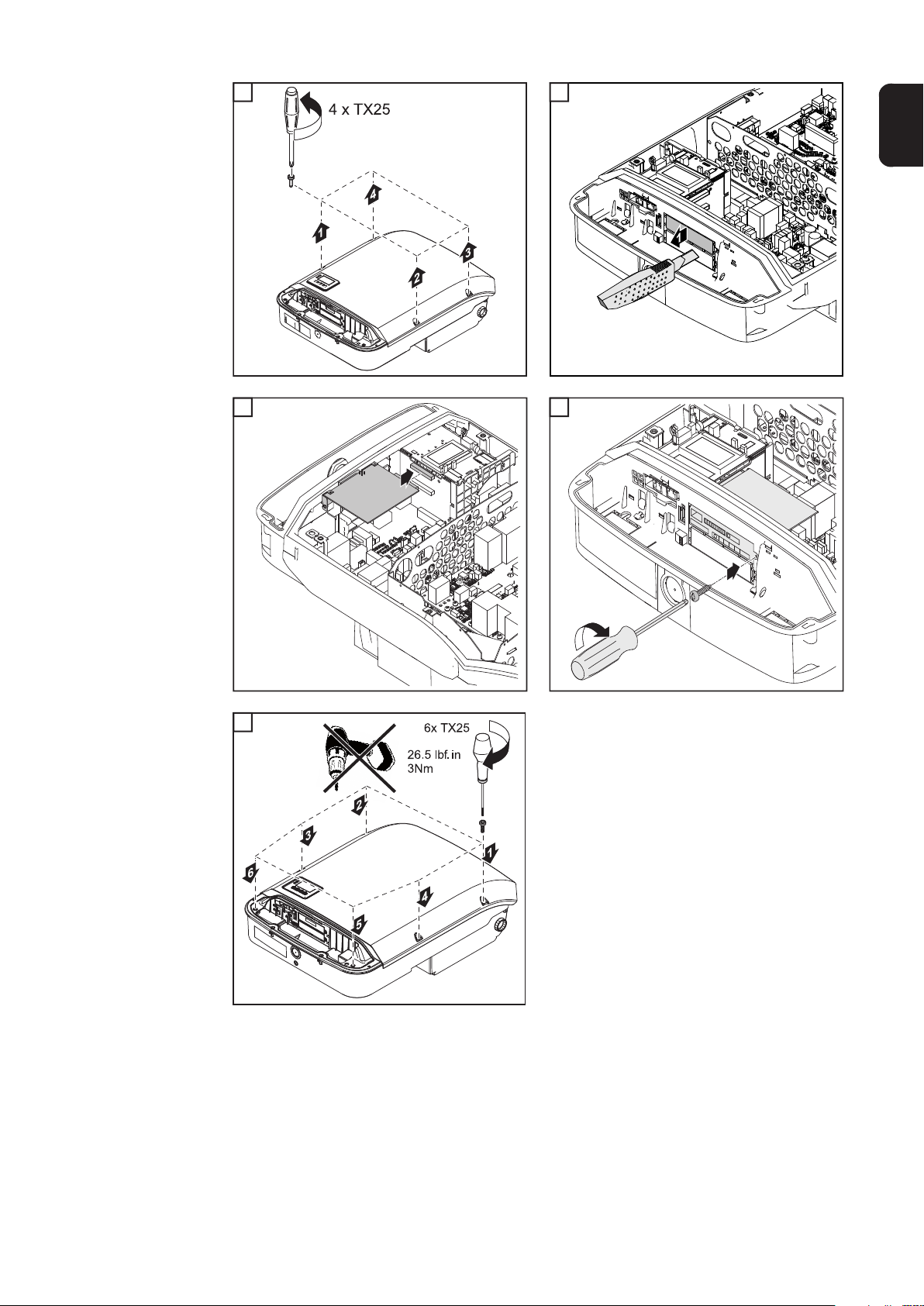
Installing Datamanager in the Inverter
WARNING!
Danger of residual voltage from capacitors.
An electric shock can be fatal.
► Wait until the capacitors have discharged. Discharge takes 5 minutes.
WARNING!
An inadequate ground conductor connection can cause serious injury and damage
to property.
► The housing screws provide an adequate ground conductor connection for grounding
the housing and should not be replaced under any circumstances by other screws that
do not provide a reliable ground conductor connection.
IMPORTANT! Follow general ESD guidelines when handling option cards.
IMPORTANT! Only one Fronius Datamanager in master mode is permitted per Fronius
Solar.Net Ring. Switch other Fronius Datamanagers to slave mode or remove them.
Unused option card slots can be closed by replacing the cover (item number
42,0405,2094), or an inverter without Fronius Datamanager (light version) can be used.
IMPORTANT! Only knock out one opening for the PC board when installing a data manager in the inverter.
44
Page 45
1 2
1
3 4
3
1
2
EN-US
4
1
TX20
2
5
10.6 lbf.in
1.2 Nm
5
45
Page 46

46
Page 47

Finally...
Page 48

Page 49

Seal Conduits
EN-US
NOTE!
InsideOutside
Condensation in the conduits can damage the inverter or the photovoltaic
system components.
DC=
Air circulation
Condensation
AC~
1
1
2
DC=
Permanently elastic sealant
AC~
4
Conduit
Conduit
Conduit
1
Conduit
To avoid undesirable air circulation and
condensation in the conduits:
► seal all conduits in use with a perma-
nently elastic sealant
► seal every incoming and outgoing con-
duit
► seal both conduit ends.
InsideOutside
3
Conduit
Seal all used conduits!
Seal every incoming and every outgoing conduit!
Seal both conduit ends!
Conduit fitting
1
1
Permanently elastic
sealant
Inverter housing
49
Page 50

Clipping the Inverter onto the Mounting Bracket
Clipping the Inverter onto the
Mounting Bracket
WARNING!
Danger due to inadequate ground conductor connection.
This can result in severe personal injury and damage to property.
► The housing screws provide an adequate ground conductor connection for grounding
the housing and should not be replaced under any circumstances by other screws that
do not provide a reliable ground conductor connection.
Due to the high weight, two people are required to clip the inverter into the mounting bracket.
NOTE!
The inverter is fitted with a lock for safety reasons, which allows the inverter to be
pivoted in the mounting bracket only when the DC main switch is off.
► Only clip on and pivot the inverter in the mounting bracket when the DC main switch is
off.
► Do not use excessive force to clip on the inverter and pivot it.
The fixing screws in the data communication area of the inverter are used to fix the inverter
to the mounting bracket. Fixing screws must be properly tightened to ensure correct contact between the inverter and the mounting bracket.
CAUTION!
Danger due to improperly tightened fixing screws.
When the inverter is in operation, this can result the formation of arcs, which in turn may
lead to fires.
► Always tighten the fixing screws with the specified torque.
Use a torque screwdriver to insert the
screws into the inverter. Do not use a conventional cordless screwdriver – the tightening torque will not be sufficiently
accurate.
Before attaching the Datcom cover, check the seals on the back for damage. If there is
damage, replacement covers (DatCom Cover Upgrade Kit) must be ordered.
50
Page 51

1 2
1
EN-US
2
ON
OFF
Lock
4.3 in.
3 4
3 4
22.1 lbf.in / 2.5 Nm
51
Page 52

5
5
22.1 lbf.in
2.5 Nm
6
6
7
7
AC
ON
OFF
Lock
2
ON
1
52
Page 53

Using for the first time
EN-US
Using the Inverter
for the First Time
WARNING!
Danger from incorrect operation and work that is not carried out properly.
This can result in severe personal injury and damage to property.
► Only qualified staff are authorized to commission the inverter and only within the scope
of the respective technical regulations.
► Read the Installation Instructions and Operating Instructions before installation and
commissioning.
When starting up the inverter for the first time, various setup settings must be selected.
If setup is stopped before it is completed, it can be started again via an AC reset. An AC
reset can be carried out by switching the automatic circuit breaker off and on again.
The country setup can only be set when starting the inverter for the first time. If the country
setup needs to be changed at a later date, contact your technical support.
1 2
1
2
y
r
t
n
u
o
C
t
c
e
l
e
S
50 Hz
International 50 Hz
1
2
1
2
Setups:
Symo 208 – 240
240N (with NL-Mon)
240 (without NL-Mon)
208N (with NL-Mon)
208 (without NL-Mon)
220N (with NL-Mon)
220 (without NL-Mon)
50 HZ
50 HN (with NL-Mon)
BR N (Brazil 220 V with NL-Mon)
BR (Brazil 220 V without NL-Mon)
Symo 208 – 240
MG1N* (Microgrid 240V with NLMon)
MG1P* (Microgrid 240 V without
NL-Mon)
MG2N* (Microgrid 220V without NLMon)
MG3N* (Microgrid 208 V without
NL-Mon)
MG3P* (Microgrid 208 V without
NL-Mon)
Symo 480
480N (with NL-Mon)
440N (with NL-Mon)
50HN (with NL-Mon)
CAL3 (California 480 V with NLMon)
HI3 (Hawaii with NL-Mon)
MG5N* (Microgrid 240 V with NLMon)
MG6* (Microgrid)
HI1 (Hawaii 240 V with NL-Mon)
HI2 (Hawaii 208 V with NL-Mon)
* For more information about "Field Adjustable Trip Points" and "Special Purpose Utility-Interactive" see
www.fronius.com/QR-link/42042102339
3 4 5
3
Loading Country Setup
CONFIG
4
5
6x
7x
1
2
4x
1
5x
2
53
Page 54

6 7 8
6
SETUP
Auto Daylightsaving
7 8
BASIC
MPP TRACKER 2
1
9
2
1
2
9
54
Page 55

Options
Page 56

Page 57

USB Stick as a Data Logger and for Updating Inverter Software
EN-US
USB Flash Drive
as a Data Logger
Data on the USB
stick
A USB flash drive connected to the USB A socket can act as a data logger for an inverter.
The logging data that is saved on the USB flash drive can be viewed directly in third-party
applications (e.g., Microsoft® Excel) at any time via the included CSV file.
Older Excel versions (up to Excel 2007) have a row limit of 65536.
If the USB stick is used as a datalogger, three files are automatically created:
- FRONIUS.sys system file:
This file saves information from the inverter that is irrelevant to the customer. The file
must not be deleted individually. Only delete all files together (sys, fld, csv).
- DALO.fld log file:
Log file for reading out data in Fronius Solar.access.
You can find additional information on the Fronius Solar.access Software in the "DATCOM Detail" operating instructions at http://www.fronius.com
- DATA.csv log file:
A log file for reading out data in a spreadsheet program (e.g., Microsoft® Excel)
(1) USB root directory
USB_Drive (1)
GALVO / SYMO / PRIMO / ECO
(2)
01 (3)
FRONIUS.sys
DALO.fld
DATA.csv
02
FRONIUS.sys
DALO.fld
DATA.csv
Data structure on the USB stick
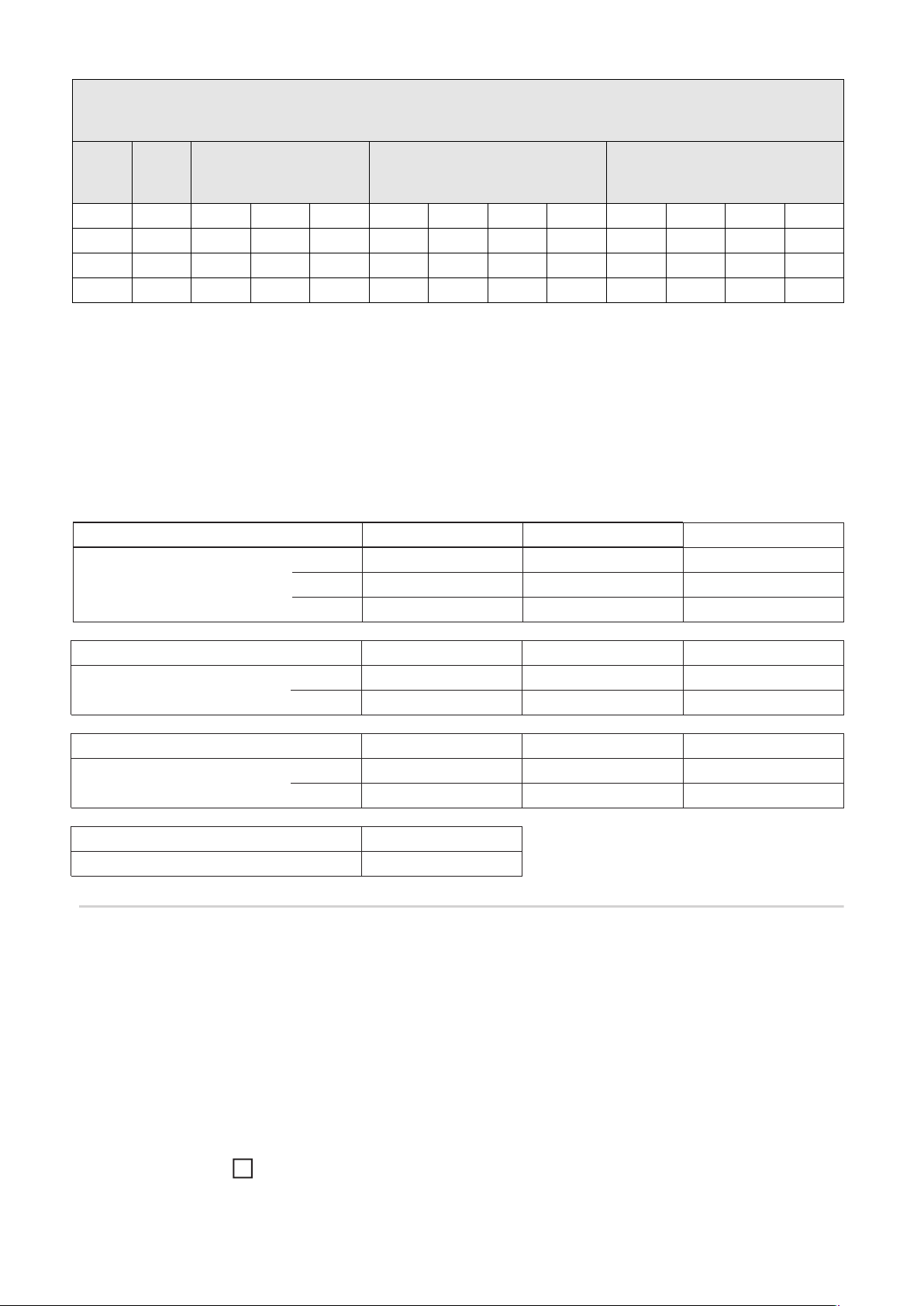
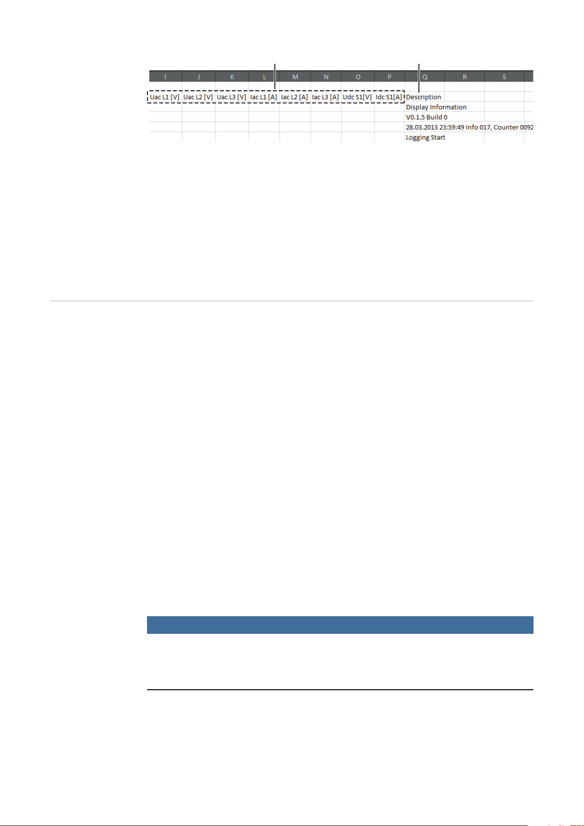
Structure of the CSV file:
(1) (2) (3) (4) (5) (6) (7)
(2) Fronius inverter (Fronius Galvo,
Fronius Symo, Fronius Primo, or
Fronius Eco)
(3) Inverter number – can be set in the
setup menu under DATCOM
If multiple inverters exist with the same inverter number, the three files are saved in
the same folder. A number is appended to
the file name (e.g., DALO_02.fld)
57
Page 58
(8) (9)
(1) ID
(2) Inverter no.
(3) Inverter type (DATCOM code)
(4) Logging interval in seconds
(5) Energy in watt-seconds with reference to the logging interval
(6) Inductive reactive power
(7) Capacitive reactive power
(8) Averages over the logging interval (AC voltage, AC current, DC voltage, DC cur-
rent)
(9) Additional information
Data Amount and
Memory Capacity
One USB thumb drive with a memory capacity of 1 GB, for example, can record logging
data at a logging interval of 5 minutes for approx. 7 years.
CSV file
CSV files can store only 65,535 rows (data records) (up to Microsoft® Excel version 2007,
afterwards there is no limit).
At a logging interval of 5 minutes, the 65,535 rows are written within approx. 7 months
(CSV data size of approx. 8 MB).
To avoid a loss of data, the CSV file should be backed up to a PC within these 7 months
and deleted from the USB thumb drive. If the logging interval is set longer, this time frame
is extended accordingly.
FLD file
The FLD file should not be larger than 16 MB. At a logging interval of 5 minutes, this corresponds to a storage duration of approx. 6 years.
If the file exceeds this 16 MB limit, it should be backed up to a PC, and all data should be
deleted from the USB thumb drive.
After you have backed up the data and removed it from the USB thumb drive, the thumb
drive should be immediately reinserted so that it can record logging data; no further steps
are required.
Notice! A full USB thumb drive can lead to loss of data or overwriting of data. When inserting the USB thumb drive, make sure that it has a sufficient memory capacity.
58
NOTE!
Risk from a full USB thumb drive.
This can result in the loss of data or data being overwritten.
► When inserting the USB thumb drive, make sure that it has a sufficient memory capac-
ity.
Page 59
Buffer Memory If the USB flash drive is removed (e.g., to back up data), the logging data is written to a
buffer memory in the inverter.
As soon as the USB flash drive is reinserted, the data is automatically transferred from the
buffer memory to the USB flash drive.
The buffer memory can store a maximum of 6 logging points. Data is logged only during
inverter operation (power greater than 0 W). The logging interval is set to 30 minutes. This
results in a time span of 3 hours for recording data in the buffer memory.
When the buffer memory is full, the oldest data in the buffer memory is written over with
the new data.
IMPORTANT! The buffer memory requires a constant power supply.
If there is an AC power outage during operation, all data in the buffer memory is lost. The
automatic night switch-off must be deactivated so that data is not lost at night (set “Night
Mode” setup parameter to ON – see the Operating Instructions for Datamanager 2.0 and
the sections “Setting and Displaying Menu Items,” “Displaying and Setting Parameters in
the ‘DATcom’ Menu Item”).
For Fronius Eco or Fronius Symo 15.0-3 208, the buffer memory also works with pure DC
voltage.
EN-US
Suitable USB
Thumb Drives
Due to the number of USB thumb drives on the market, we cannot guarantee that every
USB thumb drive will be recognized by the inverter.
Fronius recommends using only certified, industrial USB thumb drives (look for the USBIF logo).
The inverter supports USB thumb drives using the following file systems:
- FAT12
- FAT16
- FAT32
Fronius recommends that the USB thumb drive only be used for recording logging data or
for updating the inverter software. USB thumb drives should not contain any other data.
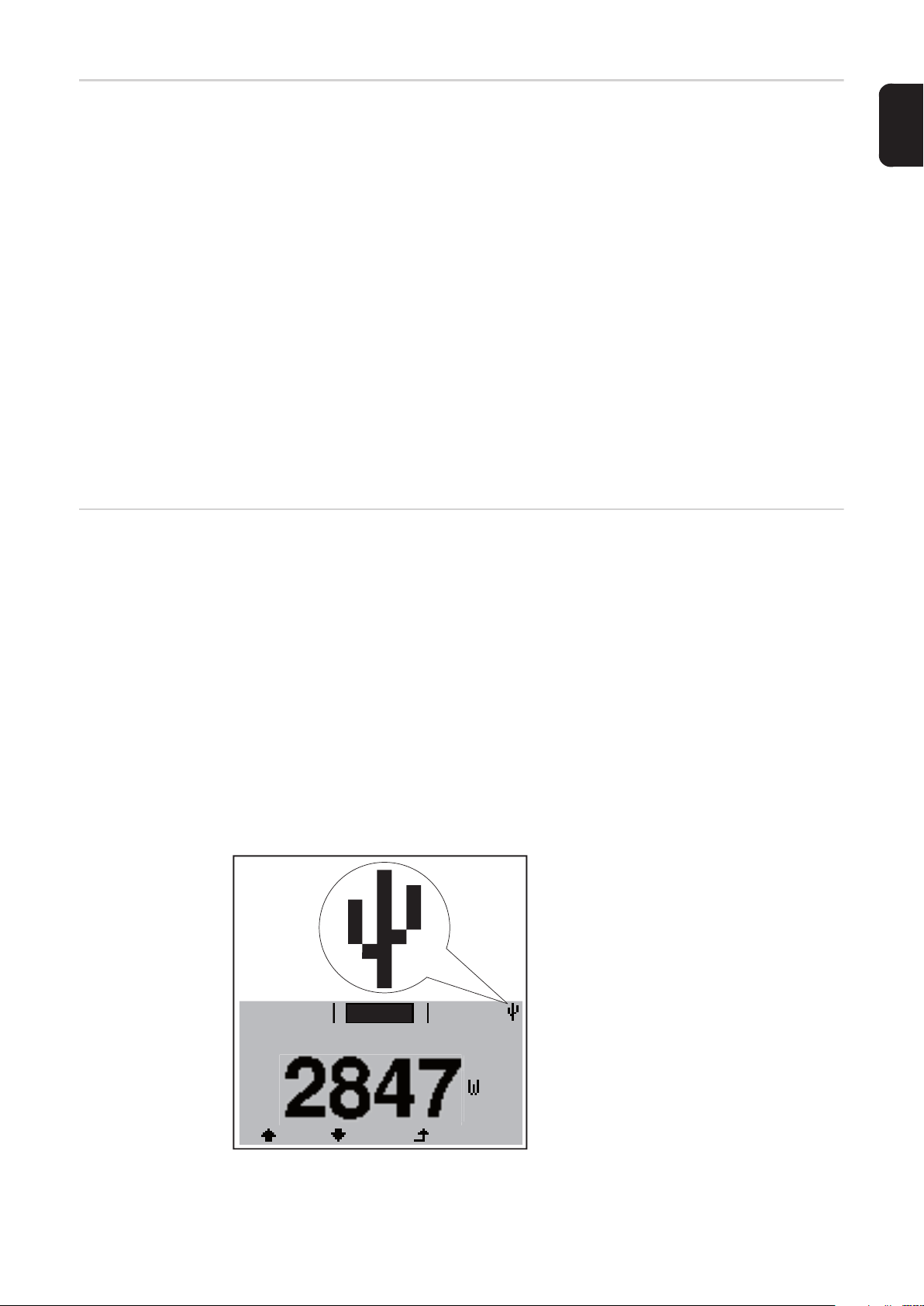
USB symbol on the inverter display, e.g., in the 'NOW' display mode:
When the inverter recognizes a USB
thumb drive, the USB symbol will appear
at the top right of the display.
When inserting the USB thumb drive,
make sure that the USB symbol is displayed (it may also be flashing).
NOW
AC Output Power
59
Page 60

Notice! Please be aware that in outdoor applications the USB thumb drive may only function in a limited temperature range.
Make sure, for example, that the USB thumb drive will also function at low temperatures
for outdoor applications.
USB Stick for Updating Inverter
Software
Removing the
USB Stick
The USB stick can be used to help end customers update inverter software via the USB
menu item in the SETUP menu item: the update file is first saved on the USB stick and then
transferred to the inverter. The update file must be saved in the USB stick root directory.
Safety information for removing a USB stick
IMPORTANT! To prevent a loss of data,
X
Do not disconnect
USB-Stick
while LED is flashing!
the connected USB stick should only be
removed under the following conditions:
- via the SETUP and "Safely remove
USB / hardware" menu items
- when the "Data Transfer" LED is no
longer flashing or illuminated.
60
Page 61

Options
Options
4 in.
100 mm
4.75 in.
120 mm
2.75 in.
70 mm
EN-US
NOTE!
A DIN rail is provided in order to mount
accessory electrical devices including,
but not limited to, overcurrent protection, metering, radio or cellular modem.
Maximum size for mounting of all devices is
4 w x 4.75 l x 2.75 inches. The installer takes responsibility for any undesired effect
on the inverter by installing an electrical device in this area. Caution should be taken
when installing a device that may output significant amounts of heat or radio interference. Always ensure that the device does
not inhibit the inverter from closing and sealing properly. Any questions about device
eligibility should be directed toward technical support.
OPTION
'ShadeCover'
- Use the ShadeCover when the inverter
is exposed to direct sunlight
- Use 4 screws for proper mounting
NO MOUNTING
61
Page 62

62
Page 63

Service and Maintenance
Page 64

Page 65

Notes on Maintenance
Maintenance Notice! For a horizontal installation position and installation outside: perform an annual
check to ensure that all screw connections are tightly fastened.
Maintenance and service work may only be carried out by Fronius-trained service technicians.
Cleaning Wipe the inverter, if necessary, with a damp cloth.
Do not use cleaning agents, scouring agents, solvents, or similar products to clean the inverter.
EN-US
65
Page 66

66
Page 67

EN-US
67
Page 68

FRONIUS INTERNATIONAL GMBH
Froniusstraße 1, A-4643 Pettenbach, Austria
E-Mail: sales@fronius.com
www.fronius.com
Under www.fronius.com/contact you will find the addresses
of all Fronius Sales & Service Partners and locations
 Loading...