

Fromm P404, P403 Operation Manual & Spare Parts List
OPERATION MANUAL / SPARE PARTS LIST
MANUAL PLASTIC STRAPPING TOOL
MODEL P404
43.0404.02
43040402.en/MAS/© 12.05
2
1 SAFETY INSTRUCTIONS
Read these instructions carefully. Failure to follow these instructions can result in severe personal injury.
Eye injury hazard
Failure to wear safety glasses with side shields can result in severe eye injury or blindness.
Always wear safety glasses with side shields which conform to ANSI Standard Z87.1.
Operation
Tool must not be used by persons not properly trained in their use. Before tensioning strap, read and
understand the tool operating instructions. Failure to follow the operating instructions or improperload
positioning could result in strap breakage.
Become familiar with your tool and keep fingers away from areas that can pinch or cut.
Cutting tensioned strap
When cutting strappi ng, use the proper strapping cutter an d keep other personnel and yourself at a safe
distance from the strap. Always stand to side of the s tr ap, awa y from the dir e ction th e loosened strap end will
fly. Use only cutters designed for strap and never hammers, pliers, hacksaws, axes, etc.
INDEX PAGE
1 SAFETY INSTRUCTIONS 2
2 TECHNICAL DATA 3
3 OPERATION ELEMENTS 4
4 ADJUSTMENT OF THE STRAP THICKNESS 5
5OPERATION 5
6 SPARE PARTS LIST 43.0404.02 10
7 EXCHANGE OF WEARING PARTS 12
7.1 Exchange of the cutter . . . . . . . . . . . . . . . . . . . . 12
7.2 Exchange of gripper and gripping jaw . . . . . . . . 13
8 WARRANTY CONDITIONS AND LIABILITY 14
9 APPROPRIATE USE 14
3
Joints
You are fully responsible to review the joints made by your tool. Become familiar with the seal control and seal
adjustment described in this operation manual.
Misformed joints may n ot sec ure t he loa d and c ould cause serio us in jury. Never handle or ship any l oad wi th
improperly formed joints.
Dispensing strap
Only dispense strap from a dispenser specifically designed for strap.
Tuck strap end back into dispenser when not in use.
Strap warnings
Never use str ap as a means of pulling or l ifting loads. Failu re to follow th ese warnings c an result in severe
personal injury.
Strap breakage hazard
Improper operation of the tool, excessive tensioning, using strap not recommended for this tool or sharp
corners on the load ca n r es ul t i n a su dde n l os s o f st rap tens io n o r in str ap breakage during tension in g, which
could result in the following:
• A sudden loss of balance causing you to fall.
• Both tool and strap flying violently towards your face.
Note as follows:
• If the load corners are sharp, use edge protectors.
• Place the strap correctly around a properly positioned load.
• Positioning yourself in-line with the strap, during tensioning and sealing, can result in severe personal
injury from flying strap or tool. When tensioning or sealing, position yourself to one side of the strap and
keep all bystanders away.
• Use the correct strap quality, strap width, strap gauge and strap tensile strength recommended in this
manual for your tool. Using strap not recommended for this tool can result in strap breakage during
tensioning.
Fall hazard
Maintaining improper fo oting a nd/or b alance whe n oper ating the tool ca n cause y ou to fal l. Before tensio ning
and especially i n elevated a reas, always es tablish good balan ce. Both feet s hould be secur ely placed on a
flat, solid surface, especially when working in elevated areas. Do not use the tool when you are in an awkward
position.
Tool hazards
A well maintained tool is a safe tool!
Check tool regularly for broken or worn parts. Do not operate a tool with broken or worn parts.
Never modify any tool. Modification can result in severe bodily injury.
2 TECHNICAL DATA
Dimensions
Length: 376 mm / 14.8"
Width: 128 mm / 5"
Height: 244 mm / 9.6"
Weight
Tool : 3.8 Kg / 8.4 lbs
Strap Dimensions
Widths: 15 - 16 mm / 0.59 - 0.63"
Thicknesses: 0.5 - 0.9 mm / 0.020 - 0.035"
4
Strap Qualities
Polypropylene, plain or embossed
Polyester, plain or embossed
Seals
P404 / 16 MM Item No.: 41.5082
Joint strength
Depending on the stra p quality the joint stren gth varies between 40 t o 80 % of the breaking st rength of the
strap.
Using low gauge s traps, the jo int strengt h is relative ly high wh ereas high g auge straps tend to have a lower
joint strength.
Tension force
The tension force is calculated by the applied manual force multiplied by 10.
Thus the tension force is 200 N x 10= 2‘000 N if the applied manual force is 200 N at the tension lever.
When applying tension, the tension force must not exceed the breaking strength of the seal joint.
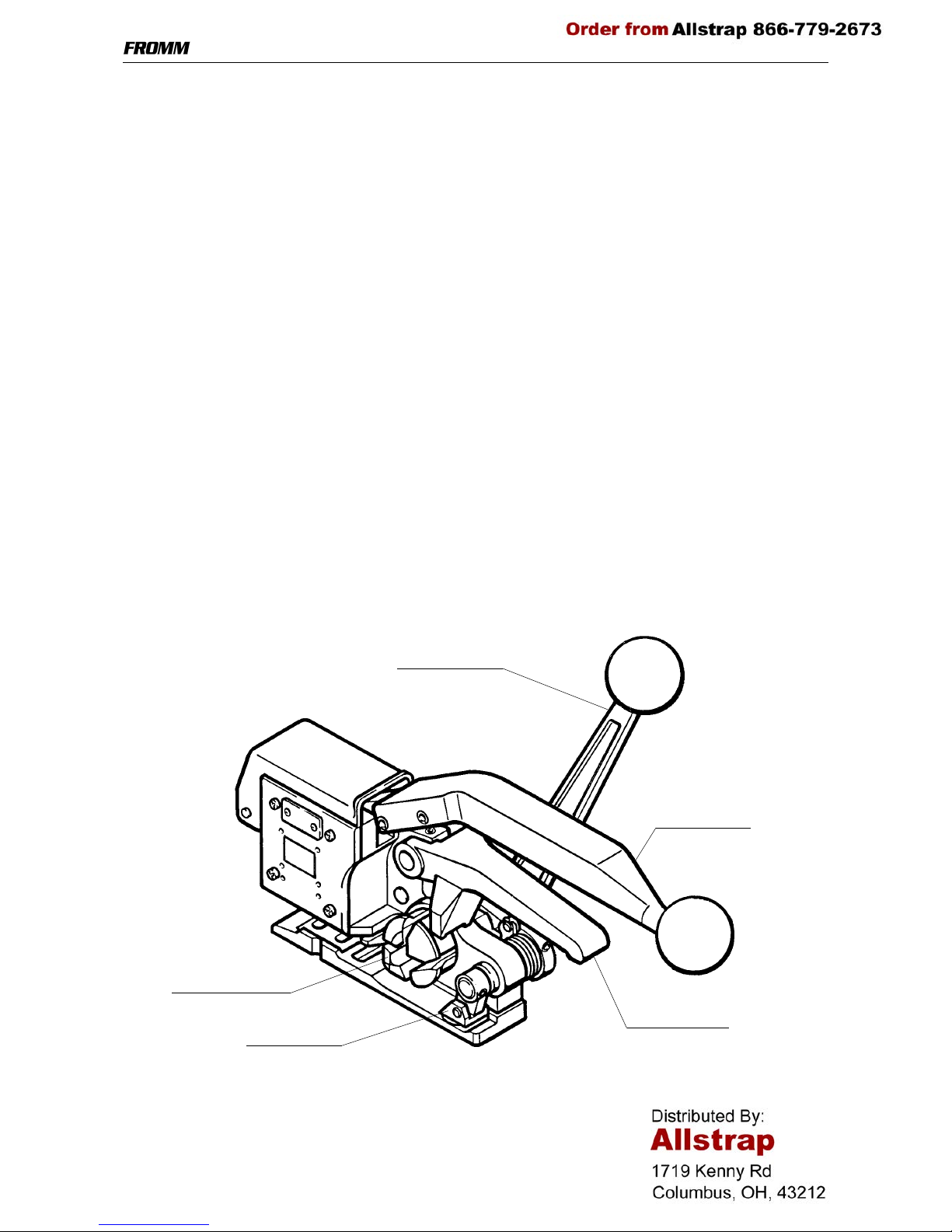
3 OPERATION ELEMENTS
Tension handle
Sealing lever
Lifting handle
Tensioning drum
Gripping jaw
5
ATTENTION! Before starting using the tool it has to be adjusted
to the strap thickness used!
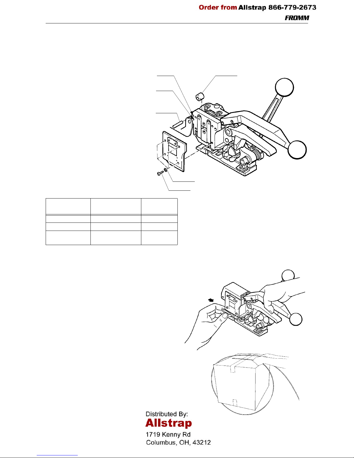
4 ADJUSTMENT OF THE STRAP THICKNESS
In order to achieve the highest possible
seal efficiency the tool must be adjusted t o
the respective stra p thickness through th e
use of the parallel pin N2.2185 and the
stop P40.2511. Please proceed as follows:
- remove the side plate
- bring the parallel pin N2.2185 and if
necessary the stop P40.2511 into
the correct position of the strap
thickness used
- reattach the side plate
- in order to avoid the strap slipping
between gripper and gripping jaw
the shims underneath the gripping
jaw have to be assembled according
to below table.
* See 7.2 changing of gripper and gripping jaw.
5 OPERATION
Introducing the seal
The seal is introduced i nto the tool from the rear side
until it hits the strap stop. Use the left hand.
Feeding the strapping around the pack age
The plastic strapping is fed around the package as
shown in the illustration.
Strap
thickness
Stop Shim*
0.50 - 0.59 mm N2.2185 in Pos. 1 2 x P40.2052
0.60 - 0.74 mm N2.2185 in Pos. 2 1 x P40.2052
0.75 - 0.90 mm N2.2185 and
P40.2511 in Pos. 2
0
N2.2185
Pos. 1
Pos. 2
P40.2511
N1.6504
N1.1910
 Loading...