

Page 1
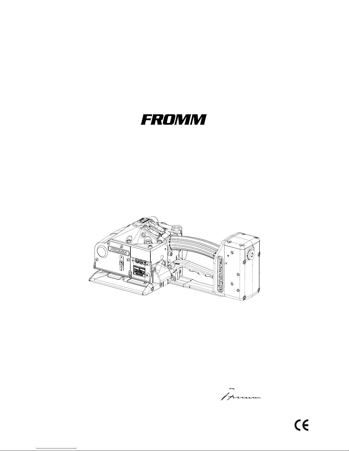
OPERATION MANUAL / SPARE PARTS LIST
PNEUMATIC
PLASTIC STRAPPING TOOL
MODEL P359
49.0524.01
CE Declaration of conformity
We declare that the machine P359
is in conformity with the following standard or
standardised documents:
2006/42/EC
Technical file at:
M.Rauch
FROMM System GmbH
Neulandstrasse 10
D-77855 Achern
25.04.2013
R.Fromm
Director
FROMM Holding AG
Hinterbergstrasse 26
CH - 6330 Cham
49052401.en/DS/© 04.13
Original instructions
Page 2

2
INDEX PAGE
1 SAFETY INSTRUCTIONS 3
2 TECHNICAL DATA 4
3 CHART OF TYPES 5
4APPROPRIATE USE 5
5 INSTALLATION 5
5.1 Compressed air connection. . . . . . . . . . . . . . . . . . . . . . . . . . . . . . . . . . . . . . . . 5
5.2 Suspension of tool. . . . . . . . . . . . . . . . . . . . . . . . . . . . . . . . . . . . . . . . . . . . . . . 6
5.3 Accessories . . . . . . . . . . . . . . . . . . . . . . . . . . . . . . . . . . . . . . . . . . . . . . . . . . . . 7
5.4 Adjustments. . . . . . . . . . . . . . . . . . . . . . . . . . . . . . . . . . . . . . . . . . . . . . . . . . . . 8
5.4.1 Preselecting of strap tension and tensioning speed . . . . . . . . . . . . . . . . . . . . . 8
5.4.2 Adjustment of the welding time . . . . . . . . . . . . . . . . . . . . . . . . . . . . . . . . . . . . . 8
5.4.3 Adjustment of the cool down time . . . . . . . . . . . . . . . . . . . . . . . . . . . . . . . . . . . 8
5.4.4 Choose operation mode . . . . . . . . . . . . . . . . . . . . . . . . . . . . . . . . . . . . . . . . . . 9
6 OPERATING CONTROLS 9
7OPERATION 10
7.1 Feeding the strap around the package . . . . . . . . . . . . . . . . . . . . . . . . . . . . . . 10
7.2 Inserting the strap . . . . . . . . . . . . . . . . . . . . . . . . . . . . . . . . . . . . . . . . . . . . . . 10
7.3 Tensioning the strap,
Operation mode Manual . . . . . . . . . . . . . . . . . . . . . . . . . . . . . . . . . . . . . . . . . 10
7.4 Sealing the straps,
Operation mode Manual . . . . . . . . . . . . . . . . . . . . . . . . . . . . . . . . . . . . . . . . . 11
7.5 Tensioning and sealing the plastic strap
Operation mode Semi-Automatic . . . . . . . . . . . . . . . . . . . . . . . . . . . . . . . . . . 11
7.6 Removing the tool . . . . . . . . . . . . . . . . . . . . . . . . . . . . . . . . . . . . . . . . . . . . . . 11
7.7 Seal - Control. . . . . . . . . . . . . . . . . . . . . . . . . . . . . . . . . . . . . . . . . . . . . . . . . . 12
8 PNEUMATIC SCHEMATIC 12
9 EXCHANGE OF WEARING PARTS 13
9.1 Exchange of tensioning wheel and grippers . . . . . . . . . . . . . . . . . . . . . . . . . . 13
9.2 Exchange of cutter, welding stop gripper and welding gripper . . . . . . . . . . . . 14
9.3 Adjustment of the coupler P35.0227 . . . . . . . . . . . . . . . . . . . . . . . . . . . . . . . . 15
10 MAINTENANCE 15
10.1 Air unit . . . . . . . . . . . . . . . . . . . . . . . . . . . . . . . . . . . . . . . . . . . . . . . . . . . . . . . 15
10.2 Cleaning: . . . . . . . . . . . . . . . . . . . . . . . . . . . . . . . . . . . . . . . . . . . . . . . . . . . . . 16
11 SERVICE 16
12 WARRANTY CONDITIONS AND LIABILITY 16
13 SPARE PARTS LIST 49.0524.01 22
Page 3
3
P359mane.fm
1 SAFETY INSTRUCTIONS
Read these instructions carefully. Failure to follow these instructions can result in severe personal injury.
Eye injury hazard
Failure to wear safety glasses with side shields can result in
severe eye injury or blindness. Always wear safety glasses with
side shields which conform to ANSI Standard Z87.1.
Operation
Tool must not be used by persons not properly trained in their use.
Before tensioning strap, read and understand the tool operating
instructions. Failure to follow the operating instructions or improper
load positioning could result in strap breakage.
Become familiar with your tool and keep fingers away from areas
that can pinch or cut.
Joints
You are fully responsible to review the joints made by your tool.
Become familiar with the seal control and seal adjustment
described in this operation manual. Misformed joints may not
secure the load and could cause serious injury. Never handle or
ship any load with improperly formed joints.
Dispensing strap
Only dispense strap from a dispenser specifically designed for
strap.
Tuck strap end back into dispenser when not in use.
Protective gloves
When handling strap, always wear protective gloves.
Strap warnings
Never use strap as a means of pulling or lifting loads. Failure to
follow these warnings can result in severe personal injury.
Strap breakage hazard
Improper operation of the tool, excessive tensioning, using strap
not recommended for this tool or sharp corners on the load can
result in a sudden loss of strap tension or in strap breakage during
tensioning, which could result in the following:
• A sudden loss of balance causing you to fall.
• Both tool and strap flying violently towards your face.
Note as follows:
• If the load corners are sharp, use edge protectors.
• Place the strap correctly around a properly positioned
load.
• Positioning yourself in-line with the strap, during tensioning and sealing, can result in severe personal injury from
flying strap or tool. When tensioning or sealing, position
yourself to one side of the strap and keep all bystanders
away.
• Use the correct strap quality, strap width, strap gauge and
strap tensile strength recommended in this manual for
your tool. Using strap not recommended for this tool can
result in strap breakage during tensioning.
Cutting tensioned strap
When cutting strapping, use the proper strapping cutter and keep
other personnel and yourself at a safe distance from the strap.
Always stand to side of the strap, away from the direction the
loosened strap end will fly. Use only cutters designed for strap and
never hammers, pliers, hacksaws, axes, etc.
Fall hazard
Keep your working area tidy. Untidiness of your working area may
cause a risk of injury. Maintaining improper footing and/or balance
when operating the tool can cause you to fall. Before tensioning
and especially in elevated areas, always establish good balance.
Both feet should be securely placed on a flat, solid surface,
especially when working in elevated areas. Do not use the tool
when you are in an awkward position.
Pay attention to the rules and regulations for preventions of
accident which are valid for the work place.
Tool hazards
A well maintained tool is a safe tool!
Check tool regularly for broken or worn parts. Do not operate a
tool with broken or worn parts.
Never modify any tool. Modification can result in severe bodily
injury.
Page 4

4
P359mane.fm
2 TECHNICAL DATA
Description of the tool
The tool model P359 has been designed to strap packages with plastic strapping. The plastic strapping is fed
around the package manually or in combination with a strap feeder. The straps are inserted in the tool,
tensioned, sealed by friction welding and separated from the strap coil.
Tool size without suspension bracket with suspension bracket
Length: 372 mm / 14.7" 446 mm / 17.6"
Width: 176 mm / 6.9" 176 mm / 6.9"
Height: 146 mm / 5.7" 239 mm / 9.4"
Weight: 8.2 kg / 18.1 lbs 8.9 kg / 19.6 lbs
Sound information
The A-weighted equivalent continuous sound level at the work place of the machine operator is
typical 82 dB (A). The sound power level is 90 dB (A).
Deviation K: 3 dB
These values were determined according to EN ISO 11204 / EN ISO 3744.
Wear ear protection!
Vibration information
The weighted effective value of the acceleration typically amounts to 1.0 m/s2.
Deviation K: 0.5 m/s
2
This value was determined according to DIN EN 20 643.
Strap material
Strap qualities: PET (Polyester) plain or embossed.
The plastic strap must be according to DIN EN 13394.
Use only plastic straps recommended by your sales shop (name and
address on the rear of the operation manual).
Strap dimensions: 19.0 - 32.0 mm / 3/4" - 1 1/4" x 0.6 - 1.53 mm / .023" - .060" (see chart of types).
Use only plastic straps with the correct strap dimensions for your tool.
Operation mode
Manual or Semi-Automatic mode
Strap tension
Tensioning force*: Adjustable from 2000 - 3500 N / 450 - 787 lbs resp.
4000 - 7000 N / 900 - 1575 lbs at 6 bar / 87 psi (see chart of types).
Tensioning speed*: 120 mm/s / 4.7" per second with steady air pressure of 6 bar/87 psi resp.
60 mm/s / 2.4" per second with steady air pressure of 6 bar/87 psi (see chart of
types).
Seal
Type of seal: Friction weld sealing
Strength of seal*: Up to approx 75% of strap tensile strength
* The value depends on the strap quality.
Page 5
5
P359mane.fm
3 CHART OF TYPES
4 APPROPRIATE USE
The tool model P359 has been designed to strap packages with plastic strapping exclusively.
For the use in hazardous areas the tool is not suitable.
The warranty / liability excludes:
• non appropriate use of the tool,
• disregard of directions in the operation manual,
• disregard of control- and maintenance instructions.
5INSTALLATION
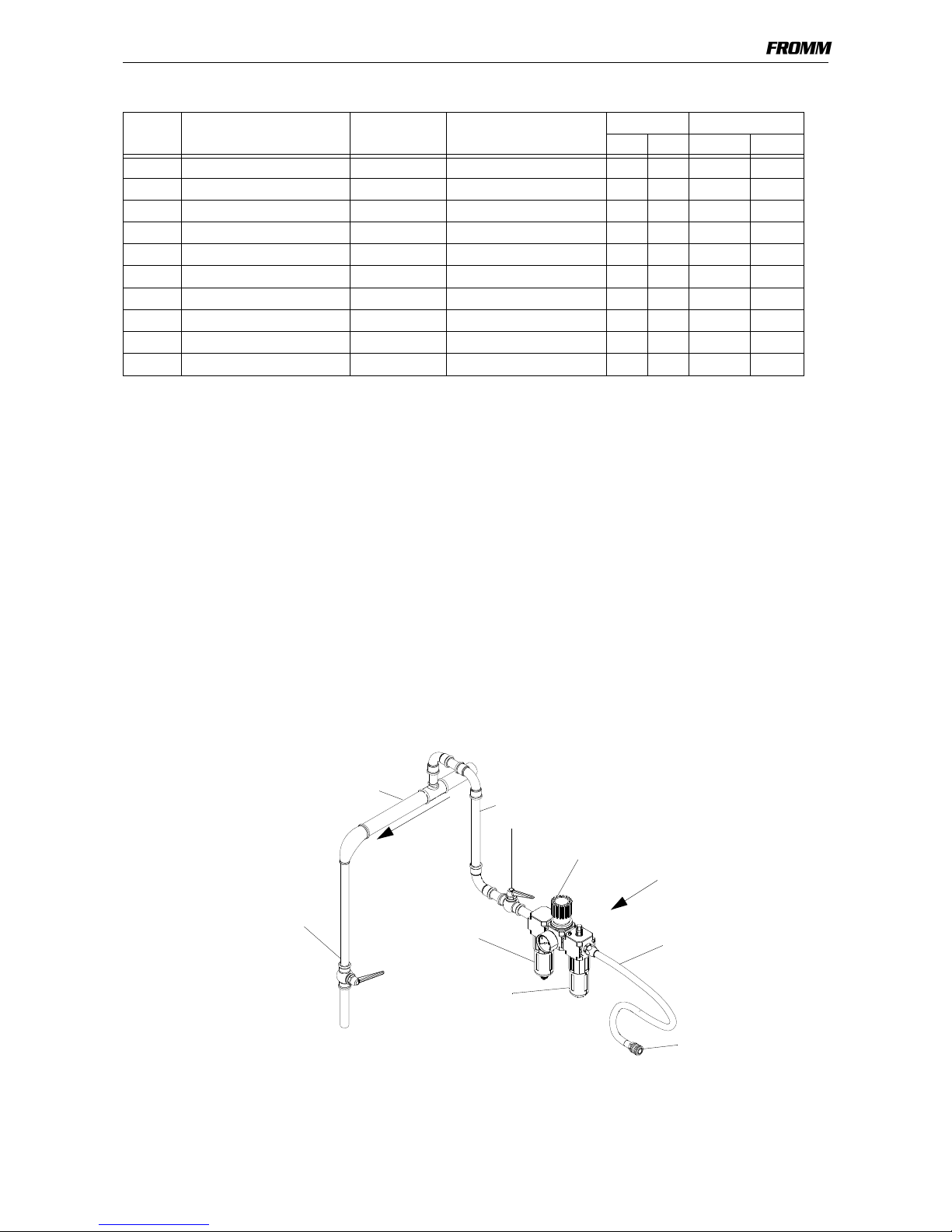
5.1 Compressed air connection
The compressed air should be connected to the tool preferably by a quick coupling.
It is very important to clean the compressed air with an air unit consisting of a separator for water and dirt, a
pressure regulator with a manometer and a lubricator (see sketch).
Item No. Model Strap width Strap thickness Max. tension Tensioning speed
N lbs. mm/s inch/s
49.0503 P359/19/0.80-1.53/3.5 19.0 mm / 3/4" 0.80 - 1.53 mm / .031" - .060" 3500 785 120 4.7
49.0504 P359/19/0.80-1.53/7.0 19.0 mm / 3/4" 0.80 - 1.53 mm / .031" - .060" 7000 1570 60 2.4
49.0511 P359/25/0.60-0.79/3.5 25.0 mm / 1" 0.60 - 0.79 mm / .023" - .030" 3500 785 120 4.7
49.0512 P359/25/0.60-0.79/7.0 25.0 mm / 1" 0.60 - 0.79 mm / .023" - .030" 7000 1570 60 2.4
49.0513 P359/25/0.80-1.35/3.5 25.0 mm / 1" 0.80 - 1.35 mm / .031" - .053" 3500 785 120 4.7
49.0514 P359/25/0.80-1.35/7.0 25.0 mm / 1" 0.80 - 1.35 mm / .031" - .053" 7000 1570 60 2.4
49.0521 P359/32/0.60-0.79/3.5 32.0 mm / 1 1/4" 0.60 - 0.79 mm / .023" - .030" 3500 785 120 4.7
49.0522 P359/32/0.60-0.79/7.0 32.0 mm / 1 1/4" 0.60 - 0.79 mm / .023" - .030" 7000 1570 60 2.4
49.0523 P359/32/0.80-1.35/3.5 32.0 mm / 1 1/4" 0.80 - 1.35 mm / .031" - .053" 3500 785 120 4.7
49.0524 P359/32/0.80-1.35/7.0 32.0 mm / 1 1/4" 0.80 - 1.35 mm / .031" - .053" 7000 1570 60 2.4
a
p
p
.
2
%
f
a
l
l
Shut off valve
Drain of main air line
Main air line min. 2
"
Air line min. 1/2"
Pressure adjustment valve
with manometer
Filter with
Lubricator
(1 - 2 drops/min)
water separator
with shut off valve
Air hose
max. length 5m (16ft.)
min. Ø inside 10mm
Coupling min. G1/4
Air unit min. G3/8
min. Ø inside 7.2mm
Page 6
6
P359mane.fm
Air pressure
Joining thread: G 1/4, minimum Ø inside 7.2mm (0.283")
Air pressure: The maximum air pressure allowed is 6.0 bar / 87 psi.
The minimum working air pressure is 5.5 bar / 80 psi.
Air flow of air unit*: Min.200 Nl/min / 7.06 cu.ft /min with a maximum pressure drop of 0.5 bar/ 7.25 psi.
Air consumption
Tensioning*: 6.5 Nl / 0.23 cu.ft uncompressed air per second with the air motor running.
Sealing*: 10.9 Nl / 0.39 cu.ft uncompressed air per second with the air motor running.
* The values have been determined according to company standard.
Oil for air unit
HL resp. CL ISO-VG 10
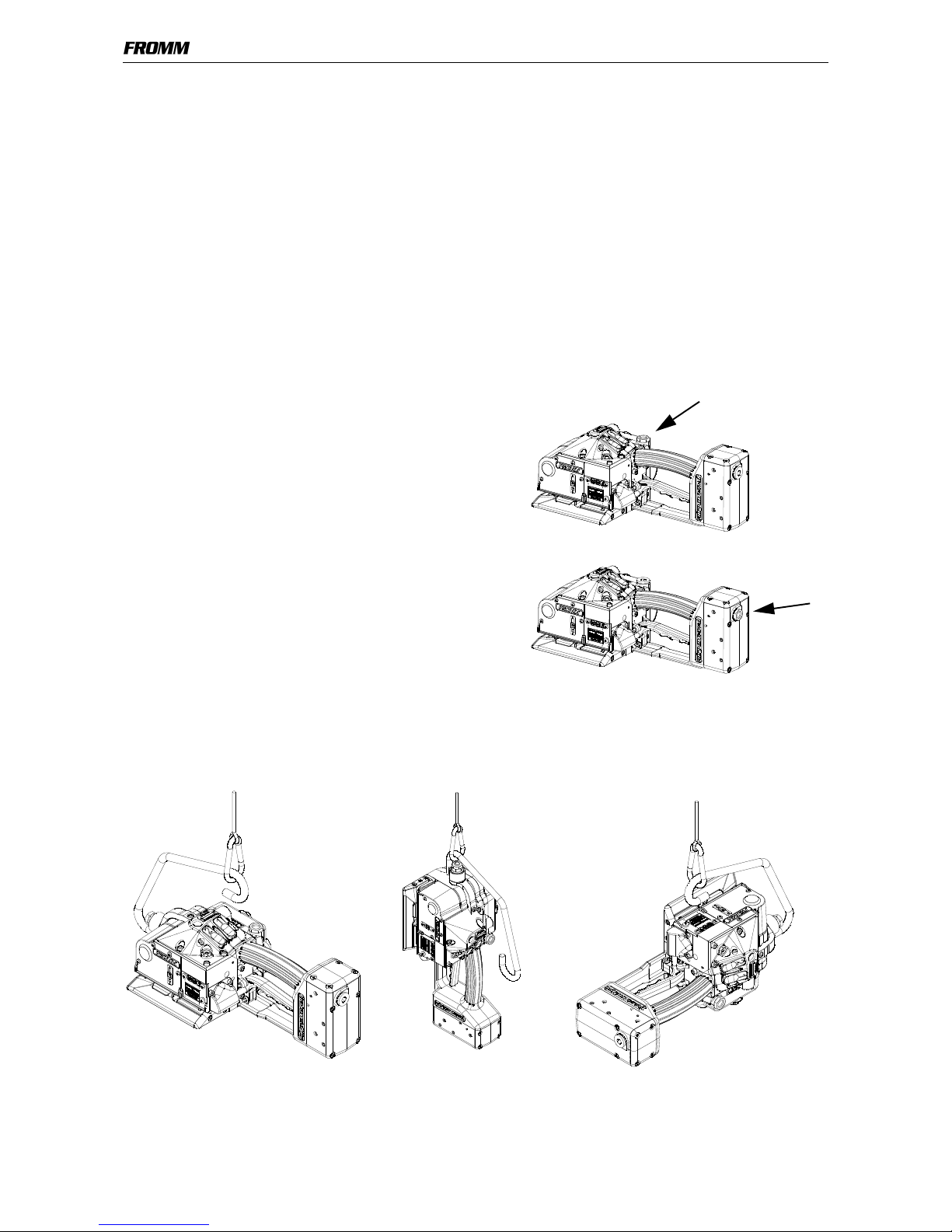
Possible connections at the tool
Factory produced the connection for the air supply is
prepared from the top.
According to requirement the connection can also be
assembled to the rear end of the tool.
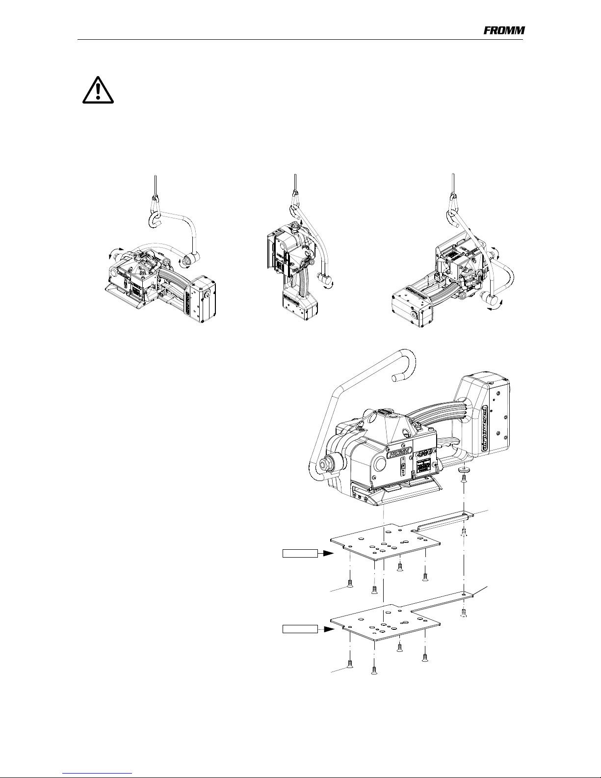
5.2 Suspension of tool
It is possible to suspend the tool on a spring loaded balancer using the suspension bracket which is supplied
with the tool. The suspension bracket has been designed in such a way, that the tool can be used for all three
working positions.
Page 7
7
P359mane.fm
5.3 Accessories
Use only parts and accessories mentioned in the operating instruction.
Using other parts or accessories can cause injuries to you and other persons.
Universal suspension
Comfortable, stepless pivoting without moving of the suspension eye.
The universal suspension can be ordered under item number P35.0230.
Wearing plate (steel)
As an option, the tool can be equipped with a
wearing plate to protect the base from
excessive wear on abrasive package surfaces.
The complete wearing plate can be ordered
together with the fastening screws under item
number P35.0231.
Protection plate (plastic)
For using the P359 on packages with sensitive
surface there can a plastic protection plate be
mounted for protecting the package.
The complete protection plate can be ordered
together with the fastening screws under item
number P35.0232.
P35.4307
N1.2163
P35.0231
P35.0232
P35.4308
N1.2163
Page 8
8
P359mane.fm
5.4 Adjustments
5.4.1 Preselecting of strap tension and tensioning speed
Do not adjust the tensioning force too high.
If the tensioning force is higher than the tensioning strength of the strap,
the strap will tear while the tensioning.
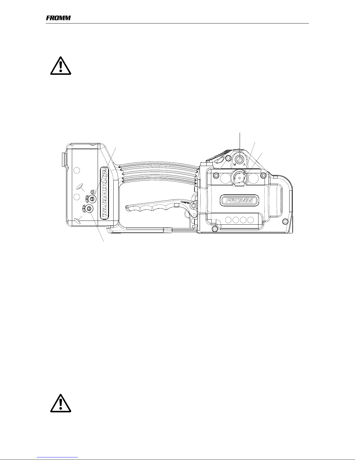
Tensioning force and tensioning speed can be preselected at the control head.
• Loose lock screw;
• press the control head against the tool and turn it.
Turning clockwise increases;
turning counterclockwise decreases the tensioning force and the tensioning speed resp..
• Tight lock screw.
5.4.2 Adjustment of the welding time
Depending on the size and quality of the strap, different welding times are required.
The welding time can be set at the throttle screw using a screw-driver 4.5 x 0.8 mm .
• Remove the cap cover.
• Turning the screw-driver clockwise increases the welding time.
• Turning the screw-driver counter-clockwise decreases the welding time.
Adjustment in small steps is recommended!
5.4.3 Adjustment of the cool down time
In order to obtain a high seal strength, the welded straps must cool down under pressure of the sealing jaws.
The required cool down time between 1 to 5 seconds depends on the strap dimension, the strap quality and
the strap tension.
The time can be adjusted at the throttle screw for cool down time using a screw-driver of 4.5 x 0.8 mm.
• Remove the cap cover.
• Turning the screw-driver clockwise increases the cool down time.
• Turning the screw-driver counter-clockwise decreases the cool down time.
Adjustment in small steps is recommended!
Do not adjust the cool down time too short.
If the cooling time is too short, the not yet solidified strap is pulled apart or
the strapping breaks.
Lock screw
Adjustment screw
Throttle screw for welding time
Throttle screw for cooling down time
Control head
for operation mode
Page 9
9
P359mane.fm
5.4.4 Choose operation mode
There are 2 operation modes possible.
1. Manual
In this operation mode is the tensioning as well as the welding of the strap started by the operator.
2. Semi-Automatic
In this operation mode the welding of the strap is automatically started as soon as the preselected tension has
been reached.
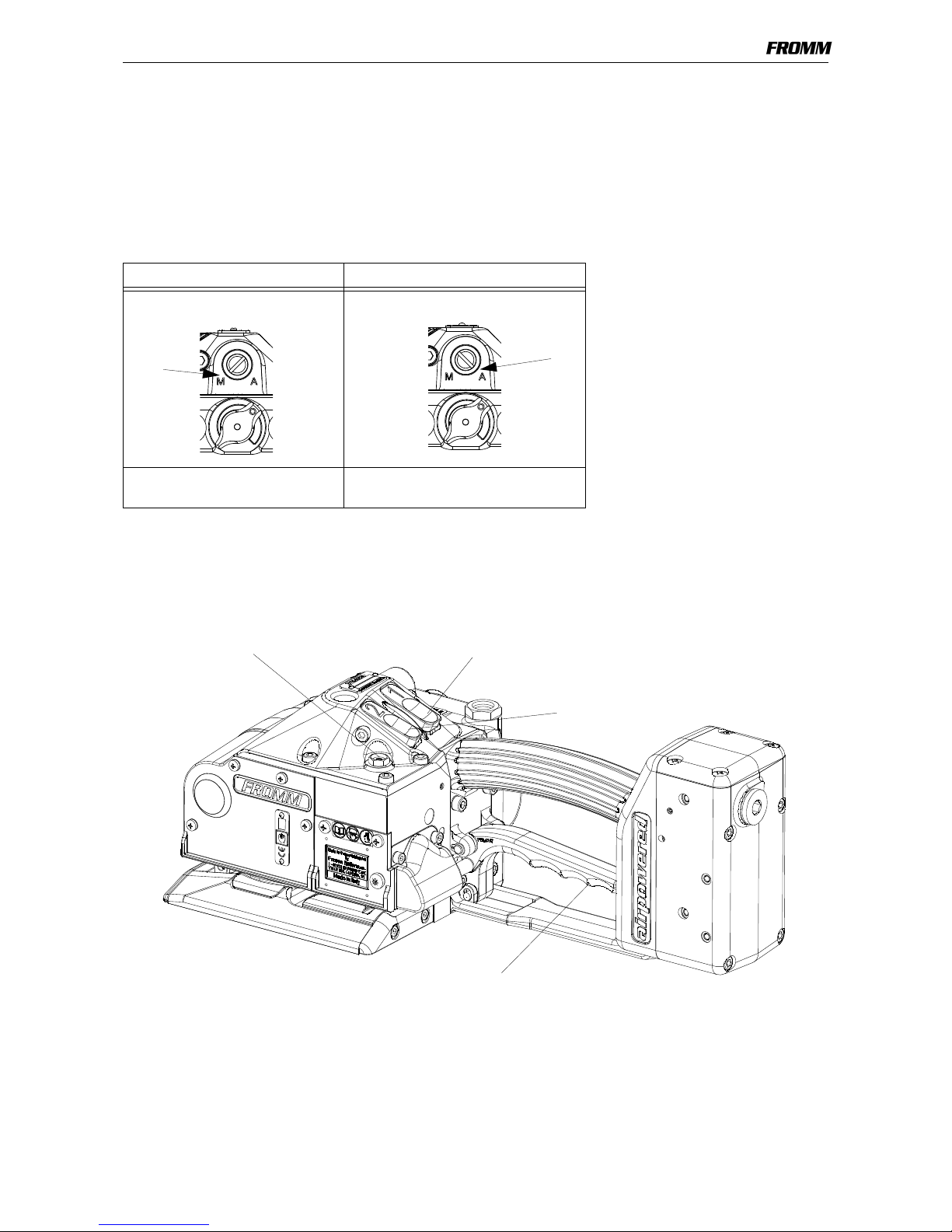
The choice of the operation mode can be made with the adjustment screw for operation mode.
6 OPERATING CONTROLS
Operation mode Manual Operation mode Semi-Automatic
Press adjustment screw in the tool and
turn clockwise till it locks.
Turn adjustment screw counter clockwise,
the screw moves to the outside of the tool.
Tension button
Handle lever
Sealing button
Signalisation pin
Page 10
10
P359mane.fm
7OPERATION
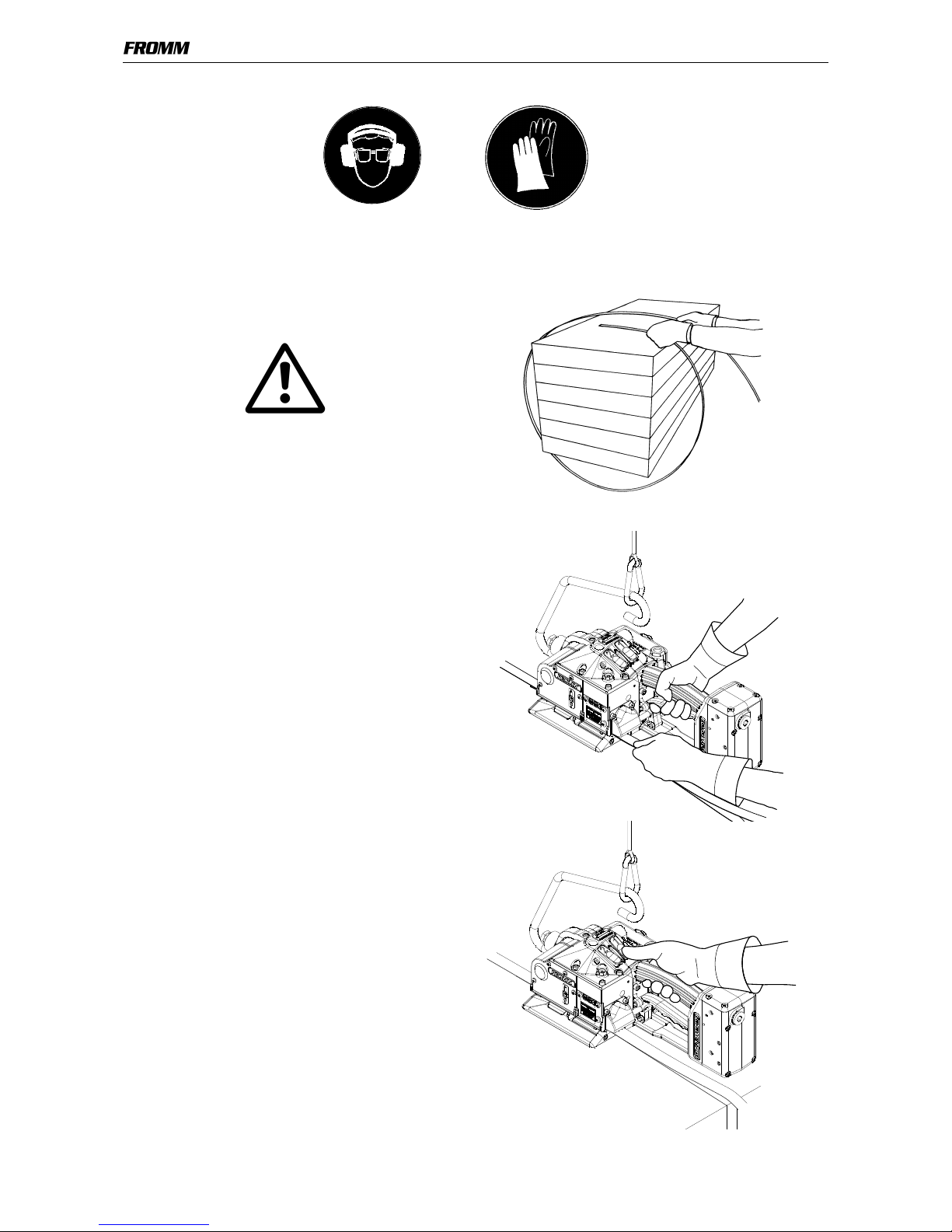
7.1 Feeding the strap around the
package
• The strapping is fed around the package as
illustrated.
Warning! The plastic strap which will be
welded must be free from oil, grease and other
dirt.
Dirty plastic straps can't be welded correct!
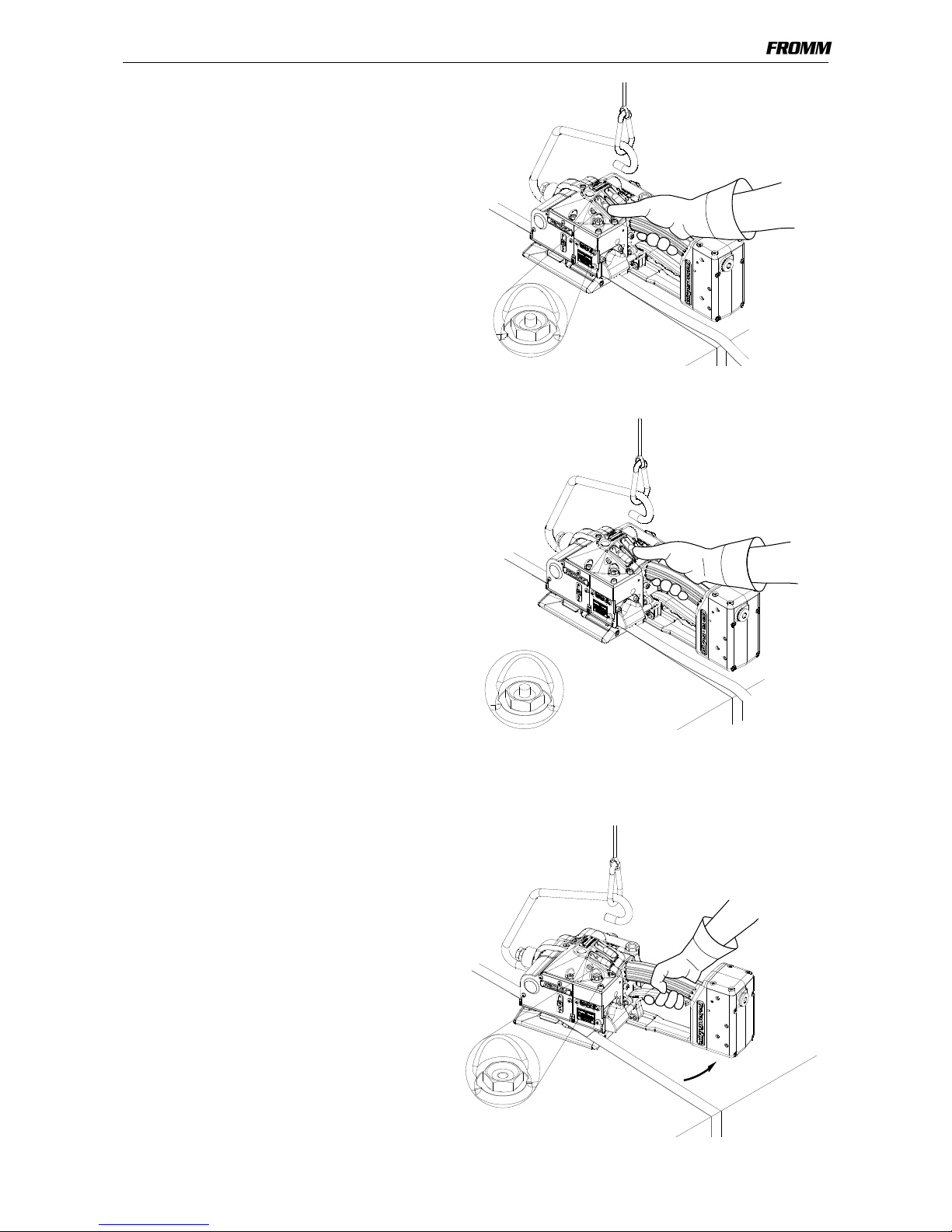
7.2 Inserting the strap
• Pull up the handle lever firmly with your right
hand.
• Insert the two straps well aligned on each other
into the strap guide using your left hand.
The lower strap end must slightly protrude the
end of the base plate.
• Release the handle lever.
7.3 Tensioning the strap,
Operation mode Manual
• Press the tension button and then release it
again after the desired strap tension has been
reached.
The tensioning operation can be interrupted and
restarted at any time.
Page 11
11
P359mane.fm
7.4 Sealing the straps,
Operation mode Manual
• Press and release immediately the sealing
button
The plastic strap is welded and cut off from the
strap coil at the same time.
The signalisation pin is extended.
After termination of the welding operation, the
welding gripper and the signalisation pin remains
in its position during the cooling down time.
During that time, the tool can not be removed from
the sealed strap.
7.5 Tensioning and sealing the
plastic strap
Operation mode Semi-Automatic
• Push tension button until the adjusted tension
force is reached.
The tensioning operation can be interrupted and
restarted at any time.
After reaching the adjusted strap tension the
sealing cycle is initiated automatically.
• Release the tension button after the sealing
process has been started.
The plastic strap is welded and cut off from the
strap coil at the same time.
The signalisation pin is extended.
After termination of the welding operation, the
welding gripper and the signalisation pin remains
in its position during the cooling down time.
During that time, the tool can not be removed from
the sealed strap.
7.6 Removing the tool
After the expiration of the adjusted cooling time
the welding jaw move upwards.
The signalsiation pin is sunken.
Now the tool can be removed from the strap.
• Pull up the handle lever,
• pull the tool right / backwards and off the
strapping.
Page 12
12
P359mane.fm
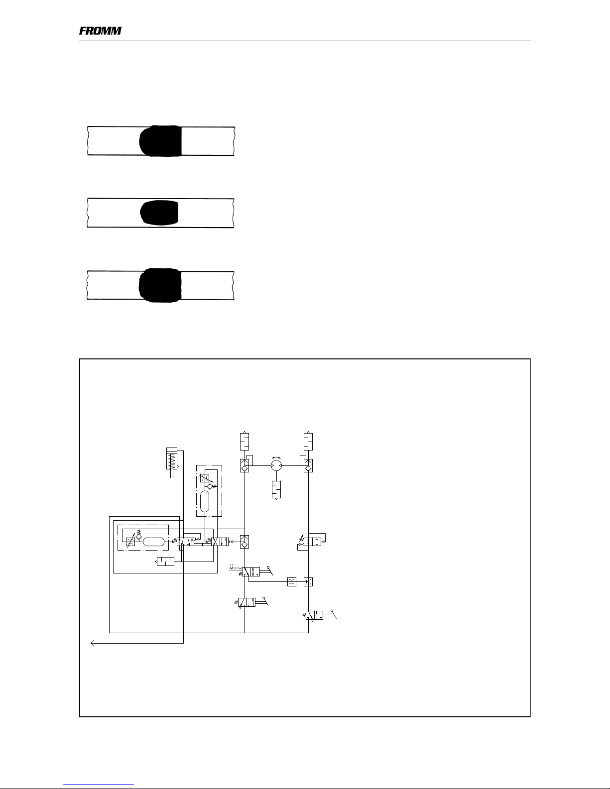
7.7 Seal - Control
A regular control of the seal is necessary. The seal can be examined visually.
Make a seal, peel it apart and examine it as follows:
Correct seal
The seal must be completely welded over the whole width of the strap
on a length of approx. 25 mm. Minor quantities of fused plastic may
overflow on sides.
Welding time too short
The plastic strap is not welded over the whole width of the strap. The
seal efficiency is insufficient.
Warning! Straps with insufficient seal strength must be removed from
the package!
Adjust the welding time (see 5.4.2).
Welding time too long
If the welding time is too long the straps are overheated. The fused
plastic overflows on both sides of the straps. The seal efficiency is
affected.
Warning! Straps with insufficient seal strength must be removed from
the package!
Adjust the welding time (see 5.4.2).
8 PNEUMATIC SCHEMATIC
P
78 9
2
14
12
17
a
1
1110
13
15
16
18
19
c
5
6
b
34
1 Tensioner valve
2 Welding start valve
3Throttle
4Throttle
5 Reversing valve
6 Exhaust silencer
7 Cooling time valve
8 Welding cylinder valve
9 Welding motor valve
10 Shuttle valve
11 Tension force control valve
12 Welding time valve
13 Exhaust silencer
14 Welding cylinder
15 Diaphragm valve
16 Diaphragm valve
17 Air motor
18 Exhaust silencer
19 Exhaust silencer
a Tensioner valve lever
b Welding valve lever
c Manual - Automatic switchover
Page 13
13
P359mane.fm
9 EXCHANGE OF WEARING PARTS
Before any maintenance work always disconnect the tool from the air supply.
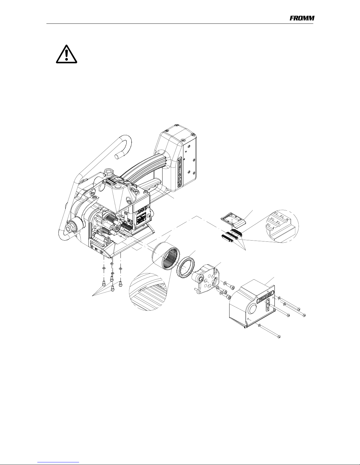
9.1 Exchange of tensioning wheel and grippers
• Unscrew cover P35.4211 and remove it;
• Unscrew end cover P35.0226, squeeze off from the body by means of a screwdriver;
• Raise tension wheel by lifting the handle lever P35.4147;
• Remove the tensioning wheel together with the bearing N31.1148 from the tool;
• Unscrew the holder P35.4184 and remove it from the body;
• Remove the grippers from the body.
Assembling in opposite order.
Assembly advise
• Lubricate the internal toothing of the tensioning wheel with Molykote BR2 plus.
• Observe the position of the tensioning wheel. The direction of rotation of the tensioning wheel is marked at
the front of the tensioning wheel (see drawing).
• Observe the position of the grippers (see drawing).
• Safe the screws N11.1115 with Loctite 222.
Tensioning wheel
P35.4184
Molykote BR2 plus
Grippers
N11.111 5
Loctite 222
P35.0226
P35.4211
N31.1148
P35.4147
Page 14
14
P359mane.fm
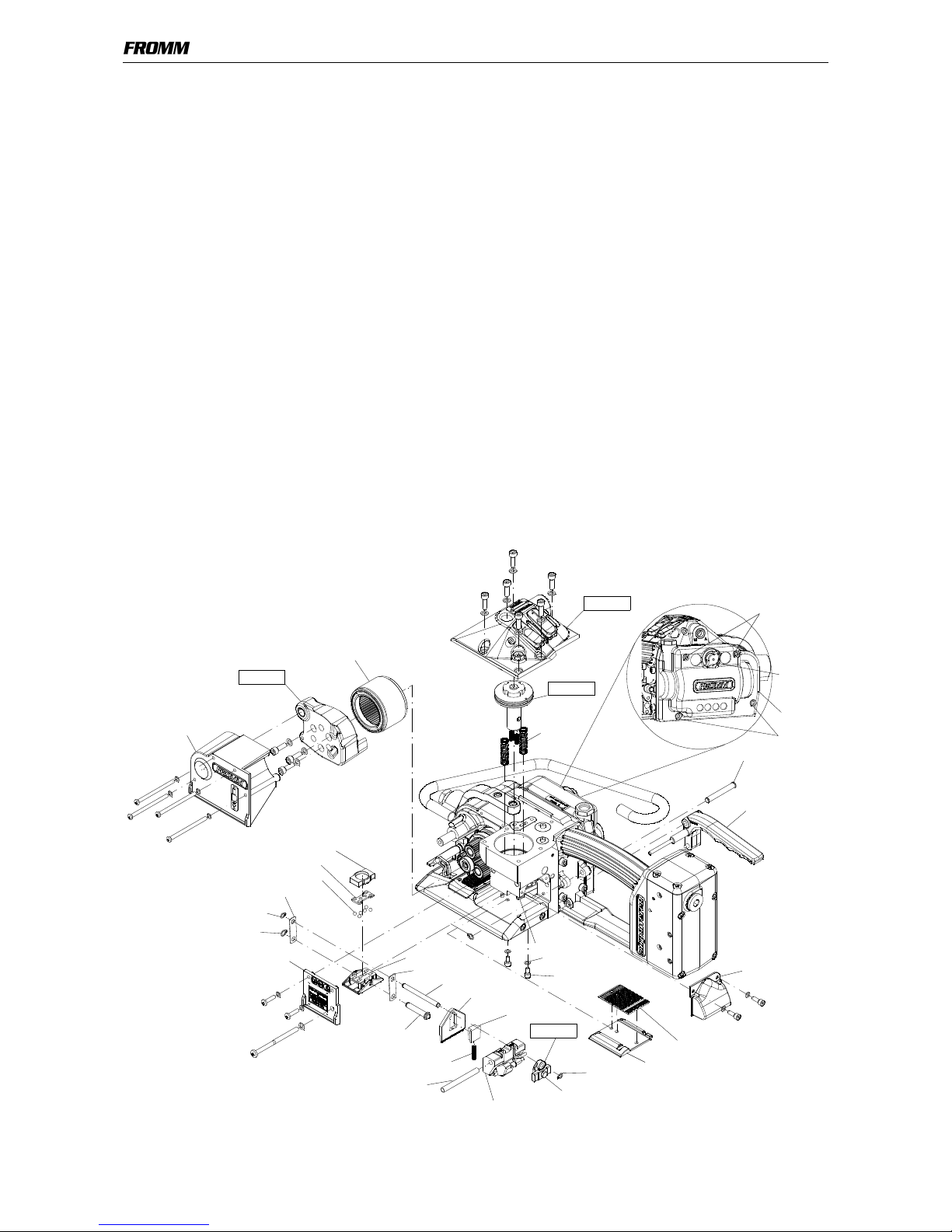
9.2 Exchange of cutter, welding stop gripper and welding gripper
• Remove cover P35.4213;
• Remove cover P35.4212 and cover P35.4211;
• Unscrew end cover P35.0226, squeeze off from the body by means of a screwdriver;
• Raise tension wheel by lifting the handle lever P35.4147;
• Remove the tensioning wheel together with the bearing N31.1148 from the tool;
• Disassemble the security ring N2.1118, pull the grip axle P35.2064 from the tool;
• Pull handle lever P35.4147 slightly back, remove from the tool to the right;
• Don’t loose screw N1.1553 at the coupler P35.0227.
• Disassemble the security ring N2.1121 from the coupler, remove the coupler;
• Pull out the centering sleeve P35.4206 from the guide case, disassemble the guide case;
• Remove the cutter P35.4198 together with the pressure spring and the guide from the driving pin P35.4110;
• Take pressure spring N21.5211 together with the spring guide P35.4199 from the cutter.
• Set control head P35.4207 to minimum tension force, fix with lock screw;
• Open the four fixation screws (2x N11.1133, 2x N11.1193) at the cover P35.4183 two turns each.
• Disassemble the cover P35.0207;
• Disassemble the two security rings N2.1121 and N2.1118 at the left hand side of the welding gripper;
• Press down the piston P35.0203.
• Disassemble the left driver P35.4111;
• Remove the two bolts P35.4110 and P35.4210 together with the driver P35.4111;
Attention! When releasing the piston, it jumps to the top due to spring pressure!
• Take piston with springs from the tool;
• Take the both springs N21.5127 from the tool;
• Remove thrust piece P32.1029 from the welding gripper;
• Lift the rocker P35.4106 behind the welding gripper with a screw driver, remove the welding gripper together with
the ball cage P32.1027 and the balls N3.1702 from the tool;
• Unscrew welding stop gripper P35.4104 from the bottom, take it from the tool.
Assembling in opposite order.
P35.4211
P35.4213
Guide case
P35.0227
N2.1118
P35.4106
P35.4107
N11.1115
Klüber Isoflex Alltime SL2
Mobilux EP2
Klüber Isoflex NBU 15
Loctite 222
Molykote BR2 plus
P35.4212
P35.4198
N2.1121
P35.4103
P35.4104
P35.4110
P35.4199
N1.1553
N11.1193
N11.1133
P35.4207
Tensioning wheel
P32.1029
P32.1027
6x N3.1702
P35.4111
N2.1118
N2.1121
N21.5211
P35.4206
P35.0226
P35.0207
N1.6504
P35.4183
P35.2064
P35.4147
P35.4210
P3 5.4111
P35.0203
N21.5127
Page 15
15
P359mane.fm
Assembly advise
• When inserting the piston pay attention to the proper seat of the piston in the thrust piece.
• Pay attention to the fitting position of the cutter (see drawing).
• Safe the screws N11.1115 with Loctite 222.
• Lubricate the rocker and the bolt P35.4210 in the area of the welding jaw with Klüber Isoflex NBU 15.
• Lubricate the balls, ball cage and the running surface of the balls on the welding gripper with Klüber Isoflex
Alltime SL2.
• Lubricate the cutter and the driver with Mobilux EP2.
9.3 Adjustment of the coupler P35.0227
The coupler is adjusted in our works.
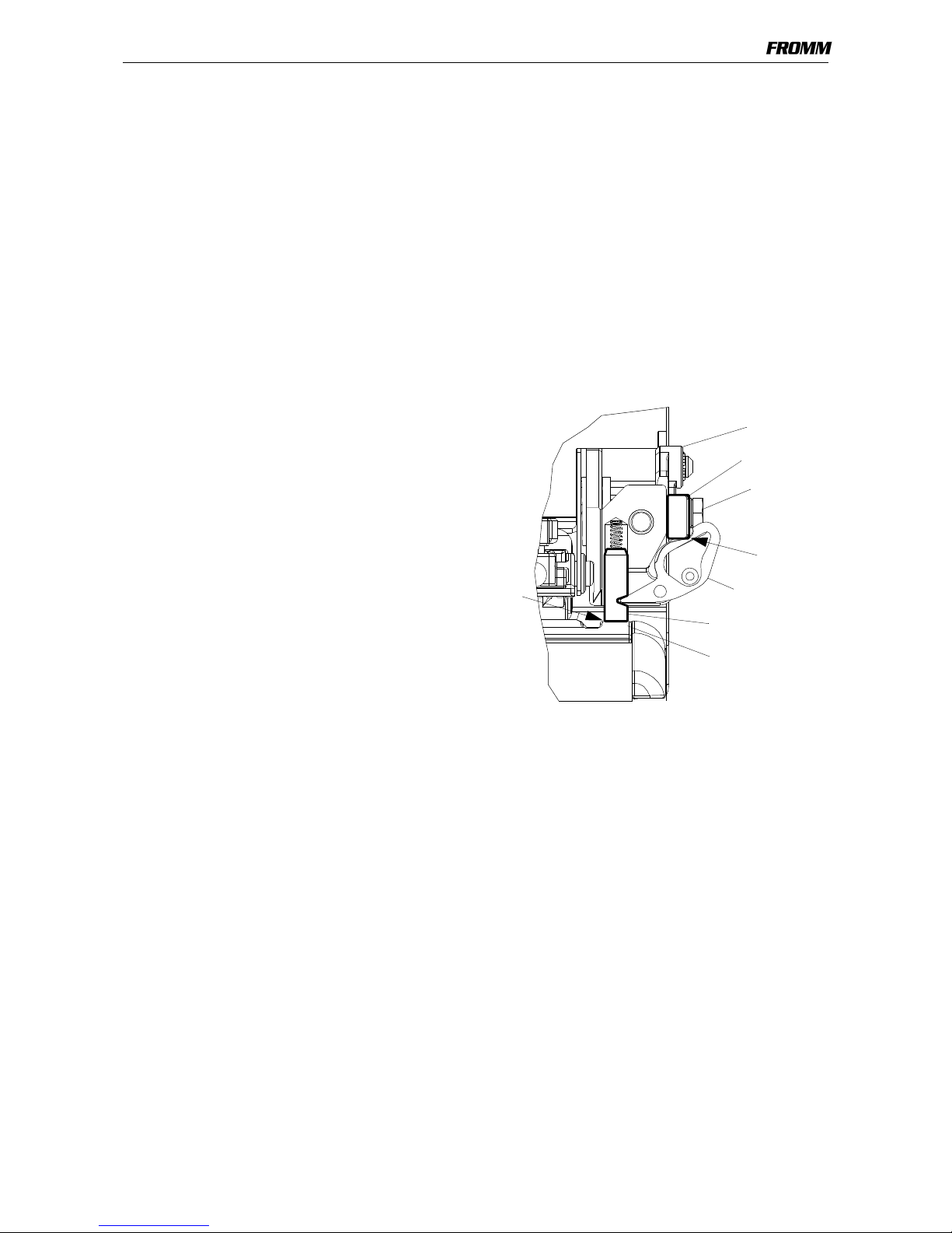
In case of replacing the seesaw lever, the coupler or the lever body, the coupler has to be readjusted.
Procedure as follows:
The tool is disconnected from the air supply.
The coupler is fitted into the tool.
• Loosen screw N1.1553.
• Displace thrust piece, so that it touches the two
seesaw levers without moving them.
• Retighten screw N1.1553.
Control:
The thrust piece must touch the seesaw levers (X1).
Both guide pins must sit on the welding stop
gripper(X2).
10 MAINTENANCE
Depending on the working conditions and the use of the tool the following maintenance has to be made
periodically:
10.1 Air unit
• Checking the air-pressure daily (never exceed 6 bar / 87psi)
• Checking oil-level daily
• The water separator must be emptied before it is full (unless automatic)
• The filter has to be cleaned following the instructions of the manufacturer of the air- unit
• Check the function and proper adjustment of the lubricator daily (approximately 1-2 drops/min.)
Coupler
Thrust piece
N1.1553
Seesaw lever
Welding stop
X1
X2
Guide pin
gripper
Page 16
16
P359mane.fm
10.2 Cleaning
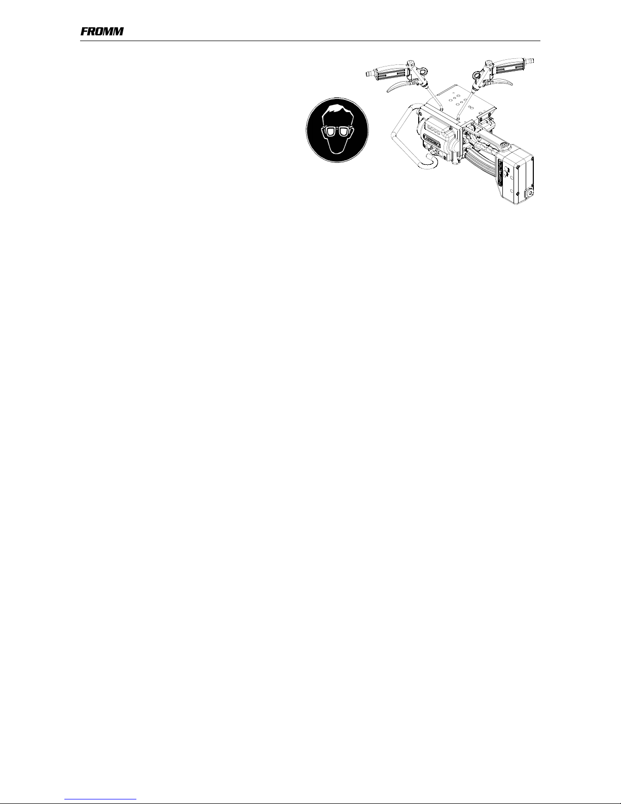
Clean tension- and sealing parts from strap
abrasion regularly using compressed air.
For that are additional openings existent in the
base plate.
Do not use any mechanical tool for cleaning.
When cleaning the surface of the tool do not use
water or aggressive solvents!
11 SERVICE
Servicing and repair work must only be carried out by authorized service centres.
If the tool breaks down or does no longer operate do not disassemble it. Send it fully assembled to the local
service center (see name and address on the rear page of this manual). Use original packing.
The pneumatic plastic strapping tool P359 is a high performance tool. We strongly recommend you to have it
serviced by an authorized service shop after 12 months at the latest if used one shift per day. If used two or
more shifts per day the tool has to be serviced after a shorter period of time.
12 WARRANTY CONDITIONS AND LIABILITY
FROMM Holding AG warrants all its strapping tools and machine heads during a period of 24 months from the
date of installation at the end-user's sight by the distributor, however, not later than 30 months from the date of
shipment to the distributor of FROMM Holding AG.
The warranty includes all deficiencies clearly resulting from poor manufacturing or faulty materials. Damage
claims as a result of production shutdowns and claims for damage to persons and to property resulting from
warranty deficiencies cannot be asserted by the customer.
The warranty excludes:
• wearing parts (tensioning wheels, cutters, punches, dies, notching knifes, grippers and motors),
• deficiencies resulting from improper installing, incorrect handling and maintaining the tool,
• deficiencies resulting from using the tool without or with defective security- and safety devices,
• disregard of directions in the operation manual,
• arbitrary modifications of the tool,
• deficient control of wearing parts,
• deficient repair works of the tool.
• Use of consumable products not recommended by FROMM Holding AG.
We reserve the right to modify the product at any time in order to improve its quality.
Page 17
17
49052401.z
A1
B
C
234
5
6
D
2P35.4169
N1.1930
1N6.6262
P35.4179
1 N6.6706
1 N6.6211
P35.4176
P35.4180
1 N6.6217
P35.4182
N3.1174
N2.5604
P35.4172
1N6.6214
N31.1163
1N6.6214
1N6.6214
N31.1163
9N3.4509
2P35.4168
1N61.6213
P35.4171
N2.2443
P35.4174
N2.2401
P35.4170
9N3.45 09
N1.21 86
2P33.1120
P35.4177
N31.1163
1N6.6214
1N6.6214
P35.4172
N2.56 04
N1.21 86
8 N61.5606
N11.1193
N1.65 03
N11.1193
N1.6503
1 N3.1702
N1.3128
P35.4207
1 P35.1344
N11.1133
N2.2102
1N6.62 35
1N6.62 68
1N21.5210
N31.1163
P35.4181
N31.1163
P35.0224
P35.0223
P35.0221
P35.0222
P35.4183
P35.4175
38x P36.1232
1N61.6213
P35.4173
P35.0237
P35.0236
N31.1150
N44.9104
N41.9129
1P35.4163
1N6.6163
1 N61.6219
1P35.4162
1 N6.6235
1P35.4161
1P35.4164
7 Loctite 222
6 Loctite 603
5 Klüber Isoflex NBU 15
4 Klüber Isoflex Alltime SL2
3 Mobil Velocite No.6
2 Molykote BR 2 plus
1 Mobil ux EP2
9 Orientation
8 Loctite 542
Page 18
18
49052401.z
A7
B
C
F
8910
E
D
1 N21.5212
1 P35.4112
1 N6.6291
1 P35.4114
1 N6.6291
1 N6.6117
1 P35.3143
1 N6.6291
1 N6.6117
1 P35.4113
1N21.5212
1N2.1606
1P35.4118
1N6.6117
1N6.6217
1P35.4117
1N6.6247
1N6.6217
1P35.4116
1N6.6217
1N6.6117
1P35.4115
8 N6.3223
1 P35.4166
N1.65 03
N2.4902
N43.9195
1N21.5212
1N6.6291
1N6.6291
1P35.3143
1N6.62 91
1N6.61 17
1P35.4121
1P35.4114
1P35.3143
N1.6503
7 P35.4165
N2.21 42
1P35.4304
N1.5144
N1.5144
1N2.5628
P35.4302
N11.1147
N1.6503
P32.1210
1 N6.6220
N1.6503
P35.4123
N11.1147
7 P35.4165
P35.4303
1 P35.3143
1P35.4119
1 P35.4167
1P35.4124
1 P35.4122
P35.0207
P35.0206
P35.0205
P35.0204
P35.0229
1 N6.6117
1N6.61 17
1N6.6117
1
7 Loctite 222
6 Loctite 603
5 Klüber Isoflex NBU 15
4 Klüber Isoflex Alltime SL2
3 Mobil Velocite No.6
2 Molyko te BR 2 pl us
1 Mobil ux EP2
9 Orientati on
8 Loctite 542
Page 19
19
49052401.z
A11
B
C
12 13 14
15
16
D
N1.1919
N1.19 68
N1.6503
N1.65 04
P35.4206
P35.4204
P35.4205
N1.65 04
N1.1553
P33.1236
P33.1237
N2.51 78
N21.5211
N1.6504
5 P35.4210
4 P35.4107 7N11.1115
N11.1116
N1.65 04
N3.23 47
N1.5602
1N6.6192
1N6.6267
1P35.4108
1N21.5127
1N2.5157
N1.6504
P35.4213
P35.0203
P35.4104
P35.4103
N41.9140
P35.4212
N2.1118
4 P32.1027
4 6xN3.1702
4 P32.1029
N2.21 62
P32.1251
N2.1121
N2.2162
P35.4110
5P35.4106
N2.2187
P35.4199
1P35.4198
N2.21 10
P35.4105
N2.21 90
N2.21 01
N3.1134
P32.1022
N3.1134
2P32.1123
2N1.63 31
2P32.1037
6N3.11 59
2N1.6331
P35.4126
N11.1116
P33.0115
P35.0137
P35.0227
P35.0202
1 P35.4111
N2.11 21
P35.4201
1P35.4109
P35.4203
1 P35.4111
7 Loctite 222
6 Loctite 603
5 Klüber Isoflex NBU 15
4 Klüber Isoflex Alltime SL2
3 Mobil Velocite No.6
2 Molykote BR 2 plus
1 Mobil ux EP2
9 Orientation
8 Loctite 542
Page 20
20
49052401.z
A17
B
C
18 19 20
21
22
D
9 N3.4519
2 P35.4152
P35.4158
1 N2.5123
N2.2172
2P35.4150
2N2.21 38
2N2.52 96
N1.6384
P35.4149
N3.3166
6 N21.2106
N31.1148
N31.1145
2 P35.4154
6 N21.2130
2 P35.4155
2 N3.2106
2 P35.4151
7 N1.2189
N31.1121
2 P35.4153
N3.3318
P35.4157
N1.2212
1P35.4146
N11.1119
P35.4209
N1.21 63
P35.4147
N11.1119
N1.6503
1 N21.5103
N1.6504
N4.9159
N2.4902
N44.9104
N1.1944
P35.4211
7N11.1115
N1.6504
N2.2147
N2.11 18
N3.1174
6 P35.4102
2 P33.2229
N31.1148
P35.4197
N3.3103
N2.2119
N1.6503
N11.1147
N2.21 54
P35.4195
P35.4191
P35.4192
P35.4184
P35.4186
P35.4187
P35.4185
2P35.4156
2 P35.4196
26x N3.2111
1 P35.4125
N1.22 18
P35.0235
P35.0216
P35.0214
P35.0219
P35.0213
P35.0215
P35.0201
P35.0226
N1.6503
P35.2064
N2.1606
P35.0234
P35.4101
N2.1614
P35.0233
N3.11 60
7 Loctite 222
6 Loctite 603
5 Klüber Isoflex NBU 15
4 Klüber Isoflex Alltime SL2
3 Mobil Velocite No.6
2 Molykote BR 2 pl us
1 Mobilux EP2
9 Orientation
8 Loctite 542
Page 21
21
49052401.z
A23
B
C
F
24 25 26
E
D
N1.1813
P35.4129
1 N6.6255
1N6.62 67
1N6.62 67
1P35.1318
1N6.62 67
P35.1317
1N6.6247
1P35.1350
1N6.62 67
1 P35.4144
1 N6.6255
1 N21.5209
1 N6.6120
1 N6.6255
1 P35.4139
1 N6.6255
1 N6.6123
1 P35.4141
1 N6.6255
1 N6.6123
1 P35.4139
1 N6.6255
1 N6.6123
1 P35.4140
1 N6.6255
1 N6.6123
1 P35.4138
1 N2.5232
1 P35.4131
1 N2.1601
1 N6.6255
1 P35.4134
1 N6.6123
1 P35.4135
1 N6.6255
1 N6.6123
1 P35.4136
1 N6.6255
1 N6.6117
1 P35.4137
1 N6.6255
1 N6.6117
1 P35.4133
1 N6.6255
1 N6.6117
1 P35.4133
1 N6.6255
1 N6.6117
1 P35.4132
1 P35.4130
1 N61.6208
N6.6157
P35.2058
P36.1305
1 N61.6208
P36.1306
N4.5137
P35.4128
N2.2101
1N6.62 83
P36.1306
N2.1301
1N6.62 83
1N61.6208
P36.1305
P35.2058
P35.4145
1N61.6208
N4.5137
N11.1193
N1.6503
N11.1193
N21.5213
N6.6157
P35.2060
N1.6503
N6.51 36
1 N6.6123
1 P35.4142
1 P35.4143
P35.0209
P35.0208
P35.0210
P35.0211
P35.0211
P35.0212
P35.4127
N21.5213
P35.4145
N2.1301
P35.2060
7 Loctite 222
6 Loctite 603
5 Klüber Isoflex NBU 15
4 Klüber Isoflex Alltime SL2
3 Mobil Velocite No.6
2 Molyko te BR 2 pl us
1 Mobil ux EP2
9 Orientati on
8 Loctite 542
Page 22
[ ] = Group * = Wearing parts
22
49052401.een.fm
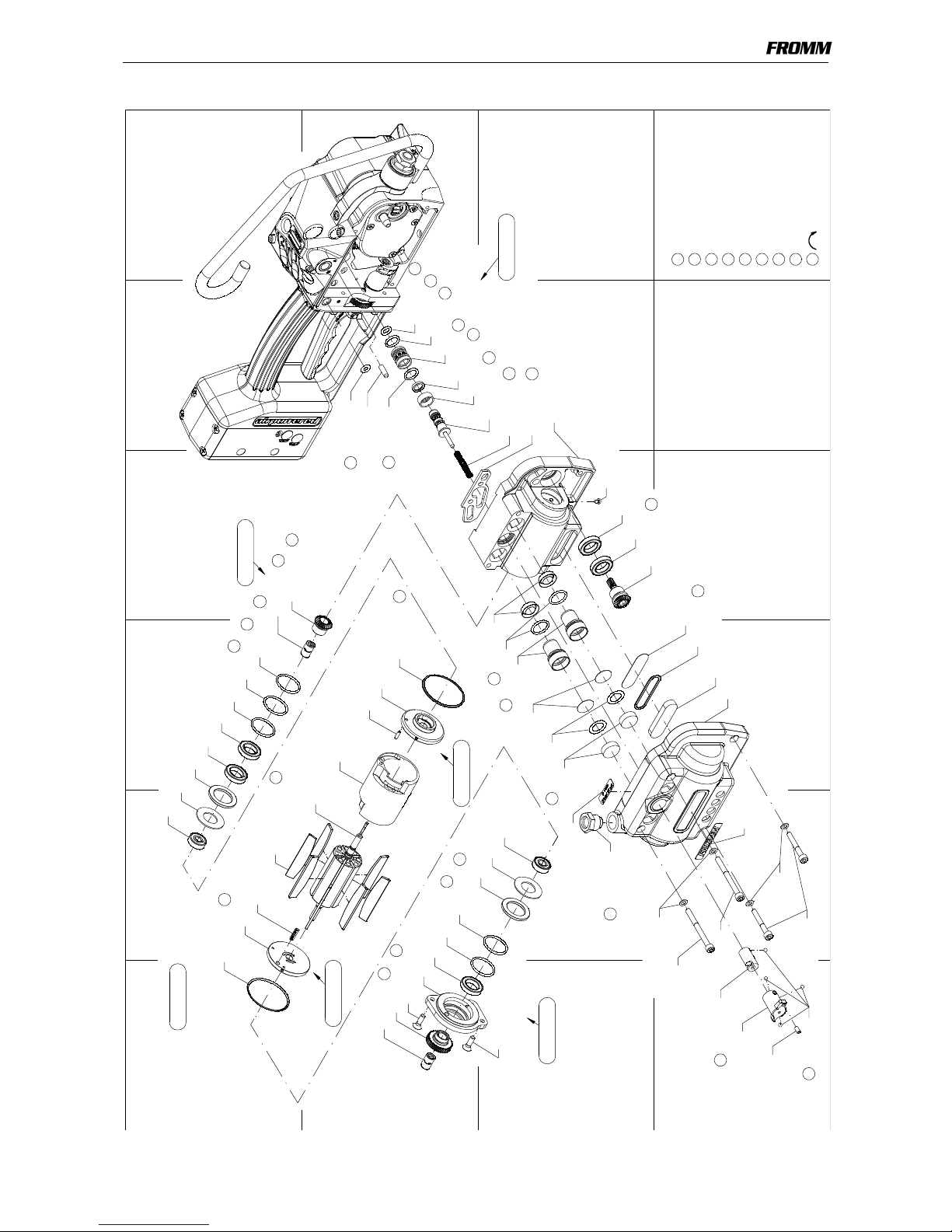
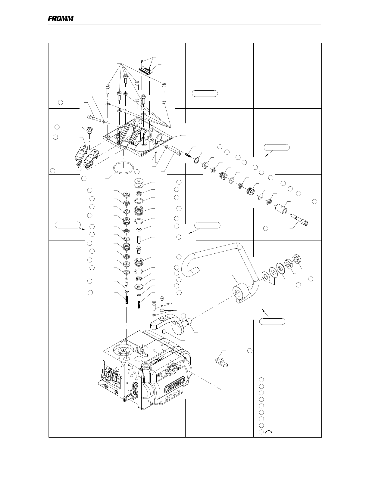
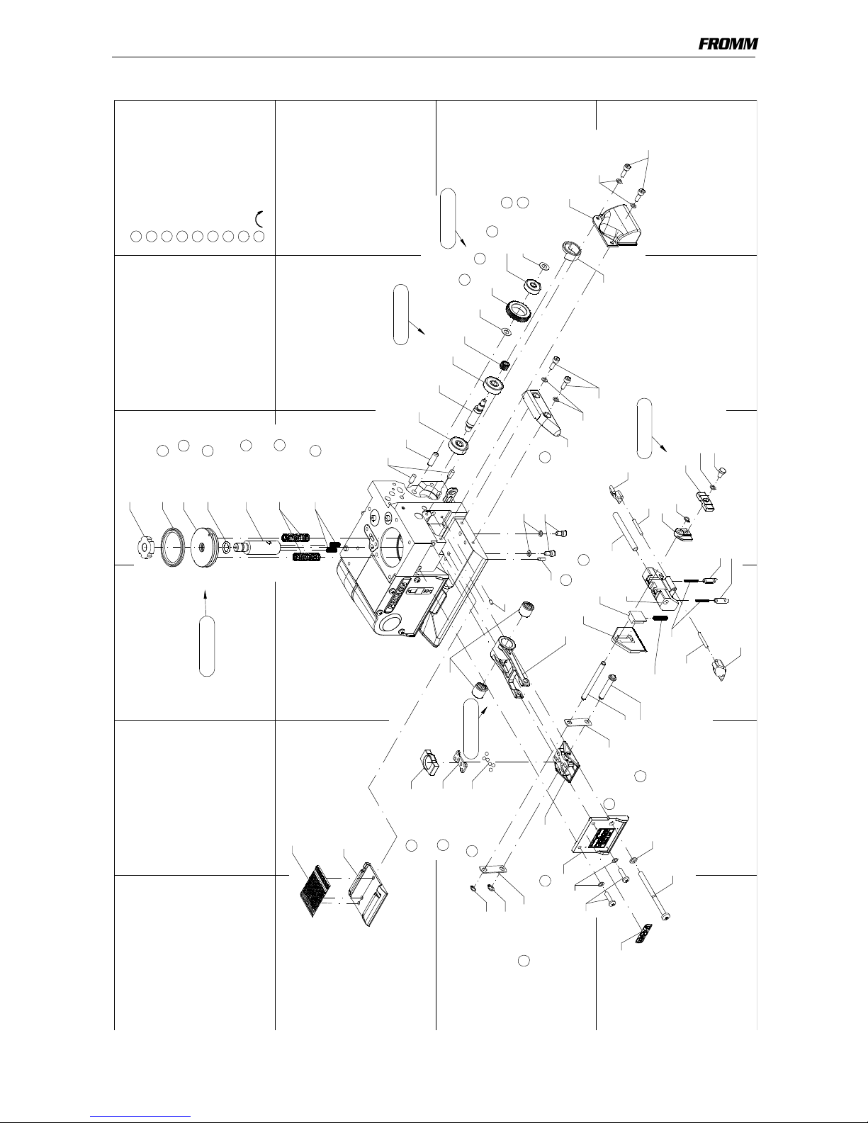
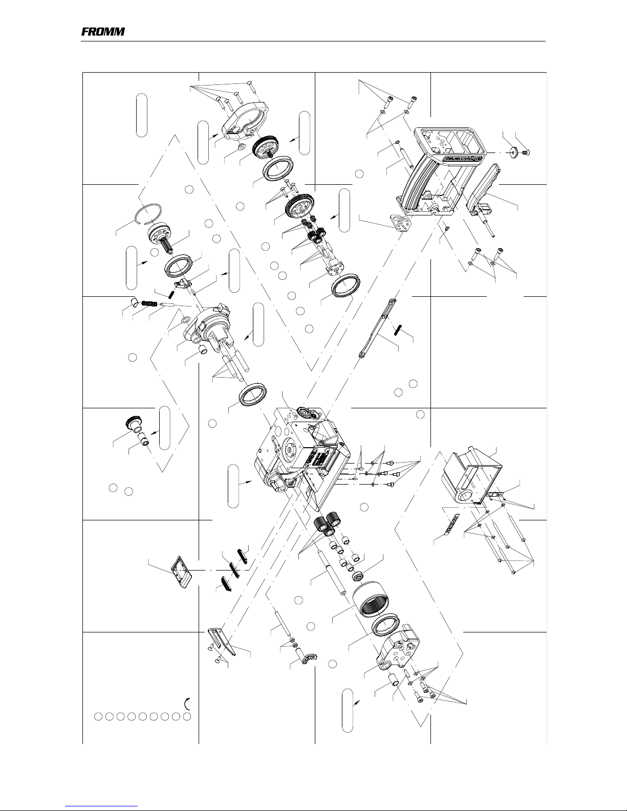
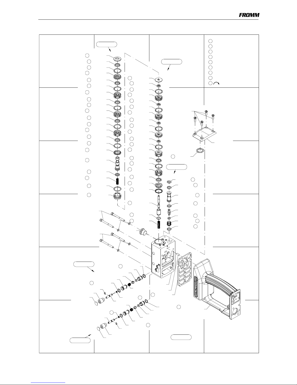
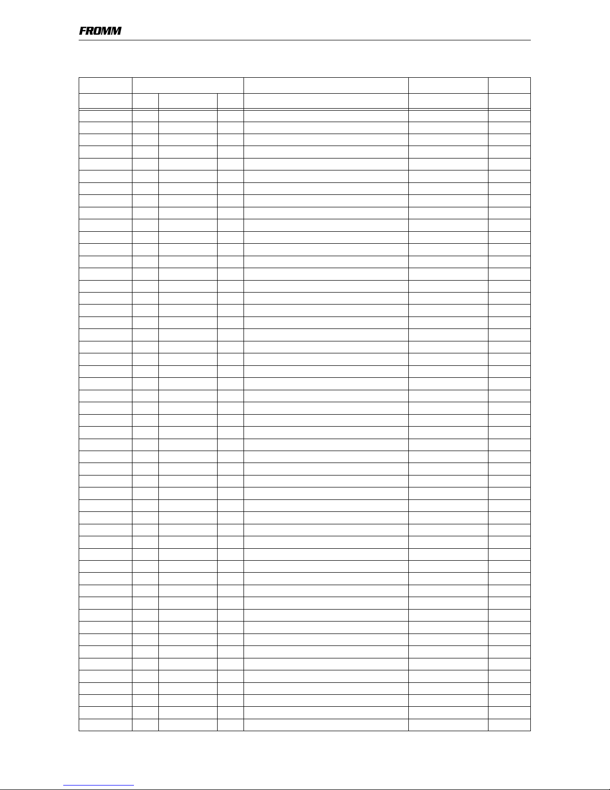
13 SPARE PARTS LIST 49.0524.01
49.0524.01 P359/32/0.80-1.35/7.0 P359.0001.01 13.03.13
Item-No. in group Pcs. Description Dimension Field
N1.1553 P35.0227 1 HEXAGON SCREW M4 X 8 D14
N1.1813 P35.0212 4 RAISED CTRS. HEAD SCREW M5 X 16 B25
N1.1919 2 SCREW M4 X 16 C11
N1.1930 P35.0224 1 FLAT HEAD SCREW M3 X 4 C4
N1.1944 4 SCREW M4 X 60 D18
N1.1968 1 SCREW M5 X 70 D12
N1.2163 1 COUNTERSUNK SCREW M5 X 12 D22
N1.2186 P35.0224 2 COUNTERSUNK SCREW M5 X 16 B1+
N1.2189 P35.0214 3 COUNTERSUNK SCREW M4 X 20 B21
N1.2212 P35.0219 4 COUNTERSUNK SCREW M4 X 25 A22
N1.2218 2 COUNTERSUNK SCREW M4 X 12 B17
N1.3128 1 SOCKET SET SCREW M4 X 8 D1
N1.5144 P35.0229 2 HEXAGON NUT M12 X 1.25 D10
[N1.5602] P35.0203 1 SLOTTED ROUND NUT M10 X 1 A14
N1.6331 2 SPACER WASHER 6 X 12 X 0.5 C15+
N1.6384 P35.0219 1 SPACER WASHER 11 X 17 X 0.5 A20
N1.6503 20 SAFETY WASHER M5 D2+
N1.6503 P35.0207 2 SAFETY WASHER M5 A7+
N1.6503 P35.0212 4 SAFETY WASHER M5 D24
N1.6504 16 SAFETY WASHER M4 C11+
N1.6504 P35.0227 1 SAFETY WASHER M4 D14
N11.1115 6 SCREW M4 X 8 C14+
N11.1116 4 SCREW M4 X 12 C14+
N11.1119 4 SCREW M5 X 20 D21+
N11.1133 2 SCREW M5 X 35 D2
N11.1147 11 SCREW M5 X 16 A7+
N11.1193 2 FLAT HEAD SCREW M5 X 55 D1+
N11.1193 P35.0212 4 FLAT HEAD SCREW M5 X 55 D23
N2.1118 2 SECURITY RING 6 C11+
N2.1121 2 SECURITY RING 5 C11+
N2.1301 P35.0211 1 CIRCLIP 6 E23+
N2.1601 P35.0208 1 SPRING RING SW12 D24
N2.1606 1 SPRING RING SW6 C22
N2.1606 P35.0205 1 SPRING RING SW6 D8
N2.1614 P35.0219 1 SPRING RING A21
N2.2101 2 PARALLEL PIN 5 m6 X 12 B14
N2.2101 P35.0212 1 PARALLEL PIN 5 m6 X 12 E25
N2.2102 1 PARALLEL PIN 5 m6 X 16 B5
N2.2110 P35.0201 1 PARALLEL PIN 4 m6 X 10 C13
N2.2119 P35.0226 1 PARALLEL PIN 4 m6 X 18 C17
N2.2138 P35.0234 1 PARALLEL PIN 4 m6 X 12 B21
N2.2142 P35.0207 1 PARALLEL PIN 4 m6 X 28 B8
N2.2147 P35.0201 2 PARALLEL PIN 3 m6 X 10 C19
N2.2154 1 PARALLEL PIN 5 h6 X 60 B17
N2.2162 2 PARALLEL PIN 3 m6 X 24 D13+
N2.2172 P35.0233 1 PARALLEL PIN 5 m6 X 30 A20
N2.2187 P35.0201 1 PARALLEL PIN 3 m6 X 6 C13
N2.2190 1 PARALLEL PIN 6 h6 X 18 B14
N2.2401 P35.0236 1 DOWEL PIN 3 X 10 B3
N2.2443 P35.0237 1 DOWEL PIN 4 X 15 A2
N2.4902 4 HAMMER HEAD BOLT 1.85 X 4.76 A8+
Page 23
[ ] = Group * = Wearing parts
23
49052401.een.fm
N2.5123 1 PRESSURE SPRING 1 X 8 X 40/12.5 A20
N2.5157 2 PRESSURE SPRING 0.6 X 4.8 X 20/15.5 B14
N2.5178 2 PRESSURE SPRING 0.32X2.82X20.5/20.5 D13
N2.5232 P35.0208 1 PRESSURE SPRING 0.80X7.80X39.0/10.5 D24
N2.5296 P35.0219 1 PRESSURE SPRING 0.5 X 4 X 24/16.5 A21
N2.5604 P35.0224 2 CUP SPRING 31.5 X 16.3 X 1.25 A3+
N2.5628 P35.0229 2 CUP SPRING 25 X 12.2 X 1/1.8 D10
N21.2106 P35.0233 3 PARALLEL PIN 8 h6 X 50 B20
N21.2130 P35.0214 3 PARALLEL PIN 5 h6 X 20 B21
N21.5103 1 PRESSURE SPRING 0.5 X 4 X 31/21.5 C20
N21.5127 2 PRESSURE SPRING 1.1 X 9.0 X 50/14.5 B14
N21.5209 P35.0209 1 PRESSURE SPRING 0.7 X 7.5 X 35.8/11.5 C24
N21.5210 1 PRESSURE SPRING 0.8 X 6.1 X 46/17.5 C5
N21.5211 1 PRESSURE SPRING 0.75 X 4.5 X 24/15.5 D13
N21.5212 P35.0204 1 PRESSURE SPRING 0.5 X 3.7 X 26.5/18.5 D7
N21.5212 P35.0205 1 PRESSURE SPRING 0.5 X 3.7 X 26.5/18.5 D8
N21.5212 P35.0206 1 PRESSURE SPRING 0.5 X 3.7 X 26.5/18.5 B9
N21.5213 P35.0211 1 PRESSURE SPRING 0.32 X 8.5 X 17/6.5 E24+
N3.1134 1 BALL BEARING 7 X 22 X7 B15
N3.1134 P33.0115 1 BALL BEARING 7 X 22 X7 C15
N3.1159 P35.0137 1 BALL BEARING 6 X 19 X 6 C16
N3.1160 P35.0213 1 BALL BEARING 40 X 52 X 7 B21
N3.1174 1 BALL BEARING 7 X 19 X 6 C18
N3.1174 P35.0224 1 BALL BEARING 7 X 19 X 6 A2
N3.1702 10 BALL 4 MM D1+
N3.2106 P35.0214 3 NEEDLE CAGE K 5 X 8 X 10 TN B21
N3.2111 6 NEEDLE CAGE K 8 X 11 X 10 TV C18
N3.2347 P35.0202 2 NEEDLE BUSH 10 X 14 X 12 C13
N3.3103 P35.0226 1 SLIDE-BEARING 10 X 12 X 20 C17
N3.3166 P35.0233 1 SLIDE-BEARING 10 X 12 X 12 A20
N3.3318 P35.0235 1 SLIDE-BEARING 8 X 10 X 4 B22
N3.4509 P35.0222 1 NEEDLE FREE WHEELING 6 X 10 X 15 B1
N3.4509 P35.0223 1 NEEDLE FREE WHEELING 6 X 10 X 15 A4
N3.4519 P35.0215 1 FREE-WHEELING 8 X 12 X 22 A19
N31.1121 P35.0216 1 BALL BEARING 45 X 58 X 7 B21
N31.1145 P35.0214 1 BALL BEARING 45 X 55 X 6 C20
N31.1148 2 BALL BEARING 40 X 52 X 7 C17+
N31.1150 P35.0224 1 BALL BEARING 8 X 19 X 6 C2
N31.1163 P35.0222 1 BALL BEARING 15 X 24 X 5 B2
N31.1163 P35.0224 4 BALL BEARING 15 X 24 X 5 A3+
N4.5137 2 PROTECTING CAP E23+
N4.9159 1 LABEL <<CE>> D19
N41.9129 1 ADHESIVE LABEL p max. 6 bar/87 psi C2
N41.9140 1 ADHESIVE LABEL 30 X 10 X 0.1 D11
N43.9195 1 TYPE PLATE <<P359>> A8
N44.9104 2 ADHESIVE LABEL <<FROMM>> D2+
N6.3223 P35.0207 1 PRESSURE READING B7
N6.5136 P35.0212 1 SEALING SCREW D24
N6.6117 P35.0204 3 SEAL 6 X 13 X 2.3 C7+
N6.6117 P35.0205 2 SEAL 6 X 13 X 2.3 C8+
N6.6117 P35.0206 3 SEAL 6 X 13 X 2.3 B9+
N6.6117 P35.0208 4 SEAL 6 X 13 X 2.3 A24+
N6.6120 P35.0209 1 SEAL 16 X 9 X 2.3 C24
49.0524.01 P359/32/0.80-1.35/7.0 P359.0001.01 13.03.13
Item-No. in group Pcs. Description Dimension Field
Page 24
[ ] = Group * = Wearing parts
24
49052401.een.fm
N6.6123 P35.0208 2 SEAL 12 X 19 X 2.3 C24
N6.6123 P35.0209 5 SEAL 12 X 19 X 2.3 A24+
N6.6157 P35.0211 1 PACKING RING 4 MM E24+
N6.6163 P35.0221 1 SEAL 10 X 13.6 X 2.3 B5
N6.6192 P35.0203 1 SEAL 45 X 36 X 2.8 A14
N6.6211 P35.0224 2 O-RING 16 X 2 C3
N6.6214 P35.0222 2 O-RING 23 X 2 B2
N6.6214 P35.0224 3 O-RING 23 X 2 A3
N6.6217 2 O-RING 15 X 2 C3
N6.6217 P35.0205 3 O-RING 15 X 2 C8+
N6.6220 P35.0207 1 O-RING 40 X 2.5 C7
N6.6235 P35.0221 2 O-RING 12 X 2 B5
N6.6247 P35.0205 1 O-RING 5 X 2.5 C8
N6.6247 P35.0210 1 O-RING 5 X 2.5 D25
N6.6255 P35.0208 6 O-RING 21 X 2 B24+
N6.6255 P35.0209 6 O-RING 21 X 2 A24+
N6.6255 P35.0212 1 O-RING 21 X 2 C25
N6.6262 1 O-RING 32 X 2.0 D3
N6.6267 P35.0203 1 O-RING 10 X 2.0 A14
N6.6267 P35.0210 3 O-RING 10 X 2.0 C25+
N6.6267 P35.0212 1 O-RING 10 X 2.0 C25
N6.6268 P35.0221 1 O-RING 6 X 2.5 B5
N6.6283 P35.0211 1 O-RING 4 X 1 E24+
N6.6291 P35.0204 3 O-RING 11.5 X 1.5 C7+
N6.6291 P35.0206 3 O-RING 11.5 X 1.5 B9+
N6.6706 P35.0224 2 DIAPHRAGM C3
N61.5606 1 REDUCING COUPLING C2
N61.6208 P35.0211 2 O-RING 9.5 X 1.5 E24+
N61.6213 P35.0224 2 O-RING 45 X 1.5 A2+
N61.6219 1 O-RING 7 X 2 B5
P32.1022 P33.0115 1 WELDING EXCENTRIC C15
P32.1027 1 BALL CAGE C12
[P32.1029] 1 THRUST PIECE B12
P32.1037 P35.0137 1 GEAR WHEEL C15
P32.1123 P33.0115 1 PINION C15
P32.1210 1 CENTERING SLEEVE E9
[P32.1251] P35.0227 1 PUSHER D14
[P33.0115] 1 WELDING EXCENTRIC B15
P33.1120 P35.0222 1 GEAR WHEEL B1
P33.1236 1 GUIDE PIN D14
P33.1237 1 GUIDE PIN D14
[P33.2229]
*
1 TENSIONING WHEEL C17
[P35.0137] 1 GEAR WHEEL C16
[P35.0201] 1 BODY B19
[P35.0202] 1 ROCKER C12
[P35.0203] 1 PISTON A13
[P35.0204] 1 VALVE C7
[P35.0205] 1 VALVE C9
[P35.0206] P35.0207 1 VALVE B10
[P35.0207] 1 COVER A9
[P35.0208] P35.0212 1 VALVE A25
[P35.0209] P35.0212 1 VALVE A24
[P35.0210] P35.0212 1 SHUTTLE VALVE C25
49.0524.01 P359/32/0.80-1.35/7.0 P359.0001.01 13.03.13
Item-No. in group Pcs. Description Dimension Field
Page 25
[ ] = Group * = Wearing parts
25
49052401.een.fm
[P35.0211] P35.0212 2 THROTTLE E23+
[P35.0212] 1 HANDLE F25
[P35.0213] P35.0219 1 GEAR WHEEL A21
[P35.0214] P35.0219 1 WHEEL C21
[P35.0215] P35.0219 1 RATCHET WHEEL A19
[P35.0216] P35.0219 1 GEAR WHEEL B22
[P35.0219] 1 GEAR A22
[P35.0221] 1 VALVE C6
[P35.0222] P35.0224 1 GEAR WHEEL C1
[P35.0223] P35.0224 1 CONICAL GEAR WHEEL A4
[P35.0224] 1 AIR MOTOR A1
[P35.0226] 1 END COVER C17
[P35.0227] 1 PUSHER D14
[P35.0229] 1 SUSPENSION E10
[P35.0233] P35.0219 1 GEAR BODY B20
[P35.0234] P35.0219 1 LEVER B21
[P35.0235] P35.0219 1 GEARING COVER B22
[P35.0236] P35.0224 1 END PLATE B3
[P35.0237] P35.0224 1 END PLATE B1
P35.1317 P35.0210 1 VALVE STEM D25
P35.1318 P35.0210 1 VALVE SHELL D25
P35.1344 1 SLIDE GATE D1
P35.1350 P35.0210 1 COUNTER SLEEVE D25
P35.2058 P35.0211 1 THROTTLE BODY E24+
P35.2060 P35.0211 1 THROTTLE SCREW F24
P35.2064 1 HANDLE SHAFT C21
P35.3143 P35.0204 2 SUSTAINING RING C7+
P35.3143 P35.0206 2 SUSTAINING RING B9+
[P35.4101] P35.0201 1 BODY B20
P35.4102 P35.0201 1 BOLT B18
[P35.4103] 1 STEEL INSERT B12
P35.4104
*
1 WELDING STOP GRIPPER B12
[P35.4105] 1 STRAP GUIDE PLATE C14
[P35.4106] P35.0202 1 ROCKER C13
[P35.4107]
*
1 WELDING GRIPPER C12
P35.4108 P35.0203 1 PISTON ROD A14
P35.4109 P35.0203 1 PISTON PLATE A14
P35.4110 1 DRIVING PIN D12
[P35.4111] 2 DRIVER C11+
P35.4112 P35.0204 1 PUSHER D7
P35.4113 P35.0204 1 EXHAUST RING C7
P35.4114 P35.0204 1 GUIDE D7
P35.4114 P35.0206 1 GUIDE B9
P35.4115 P35.0205 1 VALVE RING C8
P35.4116 P35.0205 1 SUSTAINING RING C8
P35.4117 P35.0205 1 SUSTAINING RING D8
P35.4118 P35.0205 1 DISK D8
P35.4119 P35.0205 1 PUSHER C8
P35.4121 P35.0206 1 DOWEL C10
P35.4122 P35.0206 1 SLIDE BOLT C10
[P35.4123] P35.0207 1 COVER B9
P35.4124 1 SEAL PLATE E9
[P35.4125] 1 PUSHER C20
49.0524.01 P359/32/0.80-1.35/7.0 P359.0001.01 13.03.13
Item-No. in group Pcs. Description Dimension Field
Page 26
[ ] = Group * = Wearing parts
26
49052401.een.fm
P35.4126 1 BEARING SUPPORT D15
[P35.4127] P35.0212 1 HANDLE F25
[P35.4128] P35.0212 1 VALVE HOUSING E25
[P35.4129] P35.0212 1 COVER C26
P35.4130 P35.0212 1 SEAL PLATE E25
P35.4131 P35.0208 1 VALVE STEM D24
P35.4132 P35.0208 1 INTERMEDIATE RING A24
P35.4133 P35.0208 2 SUSTAINING RING B24
P35.4134 P35.0208 1 END RING C24
P35.4135 P35.0208 1 SUSTAINING RING C24
P35.4136 P35.0208 1 SUSTAINING RING C24
P35.4137 P35.0208 1 SUSTAINING RING B24
P35.4138 P35.0209 1 END RING A24
P35.4139 P35.0209 2 SUSTAINING RING B24
P35.4140 P35.0209 1 SUSTAINING RING A24
P35.4141 P35.0209 1 SUSTAINING RING B24
P35.4142 P35.0209 1 INTERMEDIATE RING C24
P35.4143 P35.0209 1 VALVE STEM C24
P35.4144 P35.0209 1 CYLINDER D24
P35.4145 P35.0211 1 THROTTLE SEAT E24+
P35.4146 1 SEAL PLATE C21
[P35.4147] 1 HANDLE LEVER D21
[P35.4149] P35.0233 1 GEAR BODY A20
P35.4150 P35.0213 1 GEAR WHEEL A21
P35.4151 P35.0214 1 GEAR WHEEL B21
P35.4152 P35.0215 1 GEAR WHEEL A19
P35.4153 P35.0216 1 GEAR WHEEL B22
P35.4154 P35.0214 1 PLANET SHAFT B20
P35.4155 P35.0214 3 PINION B21
[P35.4156] P35.0234 1 LEVER B21
[P35.4157] P35.0235 1 GEARING COVER B22
[P35.4158] 1 ROCKER A20
[P35.4161] P35.0221 1 CONTROL ROD C5
P35.4162 P35.0221 1 END RING B5
P35.4163 P35.0221 1 VALVE SHELL B5
P35.4164 1 SEAL PLATE C5
[P35.4165] P35.0207 2 SHAFT A7+
[P35.4166] P35.0207 1 LEVER B7
[P35.4167] P35.0207 1 LEVER B7
P35.4168 P35.0223 1 CONICAL GEAR WHEEL A4
P35.4169 P35.0224 1 CONICAL GEAR WHEEL C4
P35.4170 P35.0236 1 END PLATE B3
P35.4171 P35.0237 1 END PLATE A2
P35.4172 P35.0224 2 SUPPORTING DISK C2+
P35.4173 P35.0224 1 ROTOR B3
P35.4174 P35.0224 1 JACKET B3
[P35.4175] P35.0224 1 MOTOR HOUSING C5
P35.4176 P35.0224 2 RETAINER C3
P35.4177 P35.0222 1 COVER B2
P35.4179 1 SIEVE D4
P35.4180 2 SIEVE C3
P35.4181 1 EXHAUST SILENCER D3
P35.4182 2 EXHAUST SILENCER C2
49.0524.01 P359/32/0.80-1.35/7.0 P359.0001.01 13.03.13
Item-No. in group Pcs. Description Dimension Field
Page 27
[ ] = Group * = Wearing parts
27
49052401.een.fm
[P35.4183] 1 COVER D3
[P35.4184] 1 HOLDER A18
[P35.4185]
*
1 GRIPPER B18
[P35.4186]
*
1 GRIPPER B18
[P35.4187]
*
1 GRIPPER B18
[P35.4191] 1 STRAP STOP B17
[P35.4192] 1 STRAP STOP B17
P35.4195 2 SPACER WASHER B17
P35.4196 3 PINION B18
[P35.4197] P35.0226 1 END COVER C17
[P35.4198]
*
1 CUTTER C13
P35.4199 1 GUIDE D13
[P35.4201] 1 GUIDE CASE D13
[P35.4203] 1 SEESAW LEVER D13
[P35.4204] 1 SEESAW LEVER D14
[P35.4205] P35.0227 1 THRUST PIECE D14
P35.4206 1 CENTERING SLEEVE D13
P35.4207 1 CONTROL HEAD D1
P35.4209 1 DISK D22
[P35.4210] 1 BOLT D12
P35.4211 1 COVER D19
P35.4212 1 COVER C11
P35.4213 1 COVER C16
[P35.4302] P35.0229 1 RETAINER E9
[P35.4303] P35.0229 1 SUSPENSION BRACKET D9
P35.4304 P35.0229 1 DISK D10
P36.1232
*
P35.0224 8 VANE A2
P36.1305 P35.0211 1 GUIDE E24+
P36.1306 P35.0211 1 THROTTLE HOLDER E23+
49.0524.01 P359/32/0.80-1.35/7.0 P359.0001.01 13.03.13
Item-No. in group Pcs. Description Dimension Field
 Loading...