

Fromm P355.0001.01 Service Manual
SERVICE MANUAL
PNEUMATIC PLASTIC
STRAPPING TOOL
MODEL P355.0001.01
P355.0001.01se.en.fm/MAS/© 11.03
Manual for autorized dealers and service points
SERVICE MANUAL
PNEUMATIC PLASTIC
STRAPPING TOOL
MODEL P355.0001.01

1-2
INDEX PAGE
1.1 TECHNICAL DETAILS 1-3
1.1.1 Air supply. . . . . . . . . . . . . . . . . . . . . . . . . . . . . . . . . . . . . . . . . . . . . . . . . . . . . 1-3
1.1.2 Pneumatic schematic . . . . . . . . . . . . . . . . . . . . . . . . . . . . . . . . . . . . . . . . . . . 1-4
1.1.3 Functional description . . . . . . . . . . . . . . . . . . . . . . . . . . . . . . . . . . . . . . . . . . . 1-4
1.1.4 Details of the pneumatic control system . . . . . . . . . . . . . . . . . . . . . . . . . . . . . 1-5
1.2 CONVERSION PARTS 1-7
1.2.1 Conversion parts: strap width . . . . . . . . . . . . . . . . . . . . . . . . . . . . . . . . . . . . . 1-7
1.2.2 Conversion parts: strap thickness . . . . . . . . . . . . . . . . . . . . . . . . . . . . . . . . . . 1-7
1.3 PERIODIC MAINTENANCE AND CONTROL 1-8
1.3.1 Procedure . . . . . . . . . . . . . . . . . . . . . . . . . . . . . . . . . . . . . . . . . . . . . . . . . . . . 1-8
1.3.2 Troubleshooting. . . . . . . . . . . . . . . . . . . . . . . . . . . . . . . . . . . . . . . . . . . . . . . . 1-9
1.3.3 Checklist . . . . . . . . . . . . . . . . . . . . . . . . . . . . . . . . . . . . . . . . . . . . . . . . . . . . 1-10
1.3.4 Glueing rules . . . . . . . . . . . . . . . . . . . . . . . . . . . . . . . . . . . . . . . . . . . . . . . . . 1-11
1.3.5 Lubrication rules . . . . . . . . . . . . . . . . . . . . . . . . . . . . . . . . . . . . . . . . . . . . . . 1-11
1.3.6 Assembly information . . . . . . . . . . . . . . . . . . . . . . . . . . . . . . . . . . . . . . . . . . 1-12
1.4 RECOMMENDED SPARE PARTS 1-14
1.5 ACCESSORY TOOLS 1-15
1.5.1 Use of accessory tools . . . . . . . . . . . . . . . . . . . . . . . . . . . . . . . . . . . . . . . . . 1-16
1.6 ORDERING SPARE PARTS 1-22
1.6.1 Ordering manuals . . . . . . . . . . . . . . . . . . . . . . . . . . . . . . . . . . . . . . . . . . . . . 1-22
1.6.2 Ordering address. . . . . . . . . . . . . . . . . . . . . . . . . . . . . . . . . . . . . . . . . . . . . . 1-22
1.6.3 Finding out of the tool type (item number), the serial number
and the version number: . . . . . . . . . . . . . . . . . . . . . . . . . . . . . . . . . . . . . . . . 1-23
1.7 SERVICE ADDRESS 1-23
TECHNICAL DETAILS
1-3
1.1 TECHNICAL DETAILS
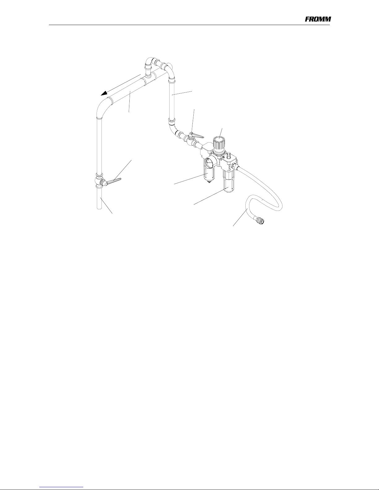
1.1.1 Air supply
Air pressure:
• The maximum air pressure allowed is 6.0 bars / 87 psi
Air unit:
•min. G3/8
• Air line in front of F.R.L.-unit min. 1/2"
• Main air line 2"
Maintenance:
• Checking the air-pressure daily
• Checking oil-level daily
• The water separator must be drained depending on developed water amount (unless automatic)
• The filter has to be cleaned regularly following the instructions of the manufacturer of the air- unit
• Check the function and proper adjustment of the lubricator daily (approximately 1-2 drops/min.)
Oil for the air-unit:
• Hl / CL ISO VG10
Shut off Valve
Drain of
Main air line
max. length 5m (16 ft.)
min. Ø-inside 9mm (3/8")
Lubricator
(app. 1-2 drops/min.)
Filter with
a
p
p
.
2
%
f
a
l
l
Shut off Valve
Pressure adjustment valve
with Manometer
water separator
coupling G1/4
2"
1/2"
TECHNICAL DETAILS
1-4
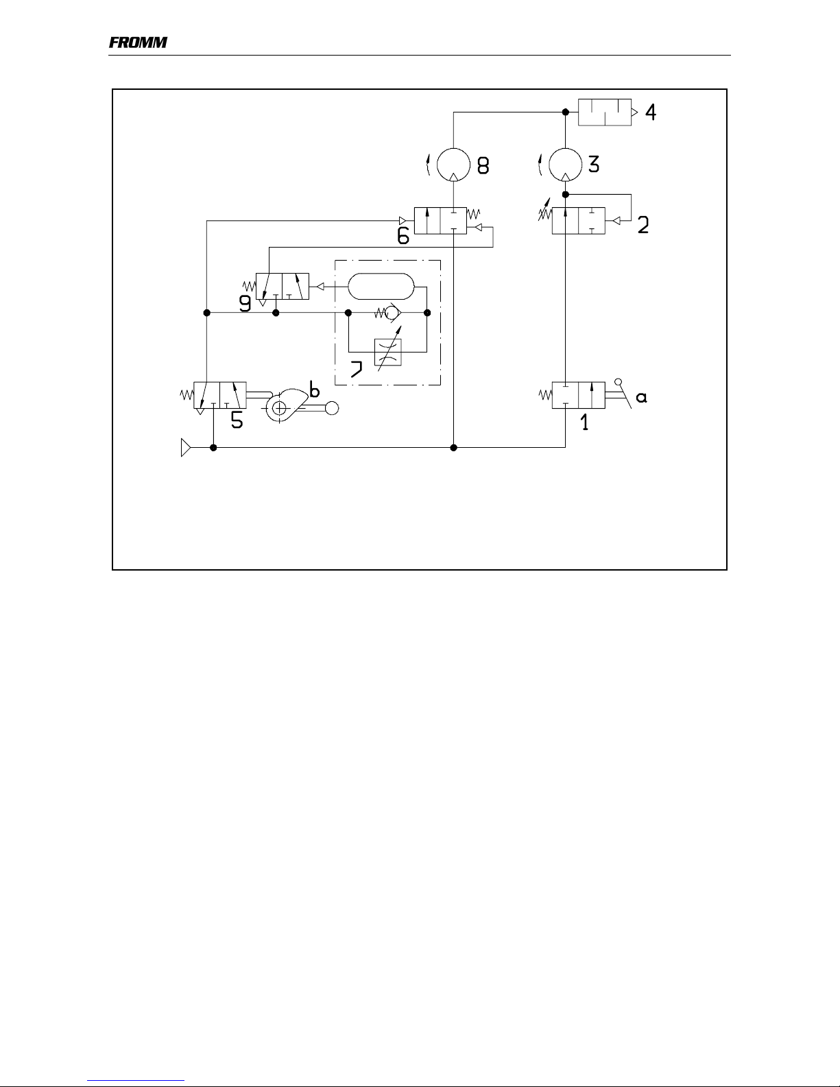
1.1.2 Pneumatic schematic
1.1.3 Functional description
A mechanical lock mechanism avoids simultaneous operation of tensioning and sealing lever.
• Pressing of the tensioning valve lever (a)
- The tensioning valve (1) is flowed through.
- The tension force control valve (2) is driven, the spring force is assisted and the valve is flown
through.
- The tensioning motor (3) starts.
- When reaching the preselected tension force the tension force control valve (2) is shut by the back
pressure of the tensioning motor.
- The motor stops.
- A return movement of the tension wheel is blocked by the needle free wheeling N3.4509.
- The tensioning valve lever (a) can be released.
• Activating the sealing valve lever (b)
- The welding valve (5) is flown through.
- The welding motor valve (6) is driven and releases the air flow to the welding motor (8).
- The welding motor (8) starts.
- At the same time the air is present at the turn off valve (9) and the welding time valve (7) is flown
through.
- When the preselected welding time (pressure) is reached the turn off valve (9) is driven.
- The turn off valve resets the welding motor valve (6) in combination with the spring pressure.
- The welding motor stops.
After the welding operation the welding lever (b) must be kept pressed in the welding position for 1-2 seconds in order to
let the welding seam cool down.
The outgoing air escapes in each case through the exhaust silencer (4).
Pos. Description Pos. Description Pos. Description
1 Tensioner valve 6 Welding motor valve a Valve lever for tensioning
2 Tension force control valve 7 Welding time valve b Valve lever for welding
3 Tensioning motor 8 Welding motor
4 Exhaust silencer 9 Turn off valve
5 Welding valve
P
TECHNICAL DETAILS
1-5
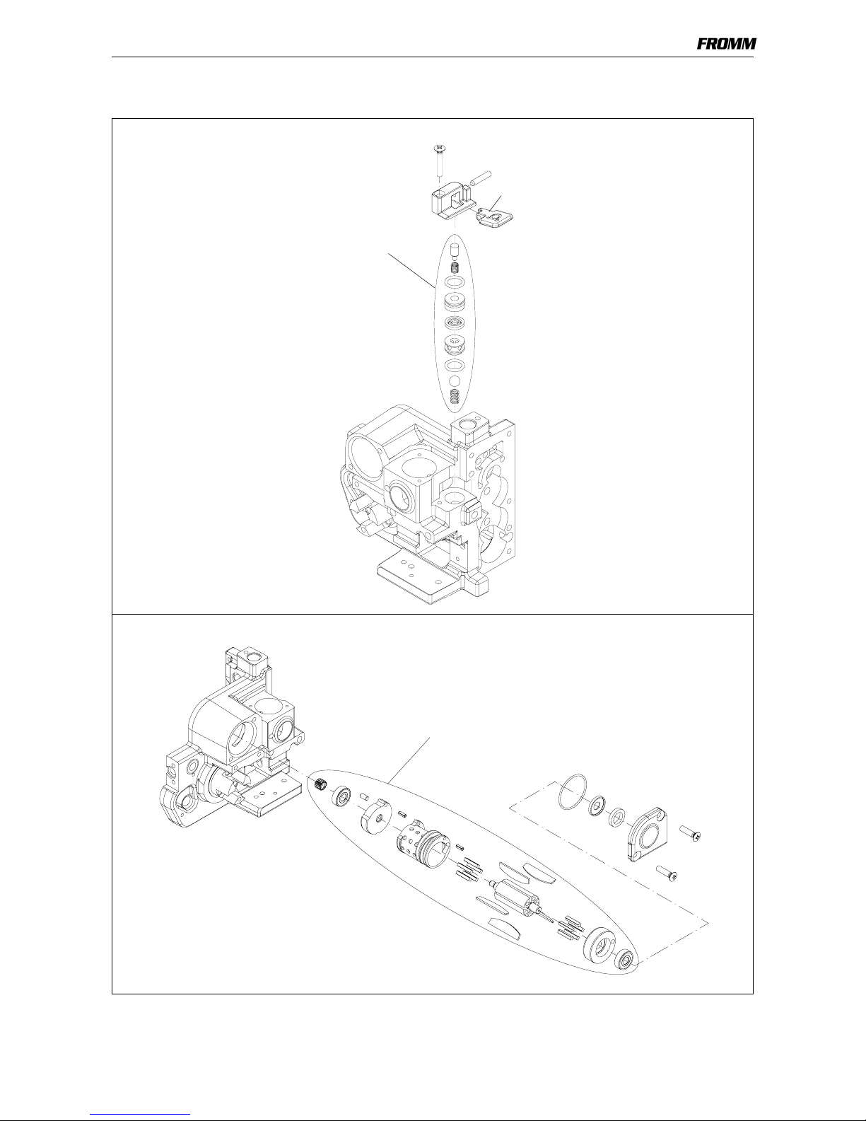
1.1.4 Details of the pneumatic control system
(Valve numbers correspond to the pneumatic schematic)
1 Tensioner valve
a Valve lever for tensioning
3
Tensioning motor
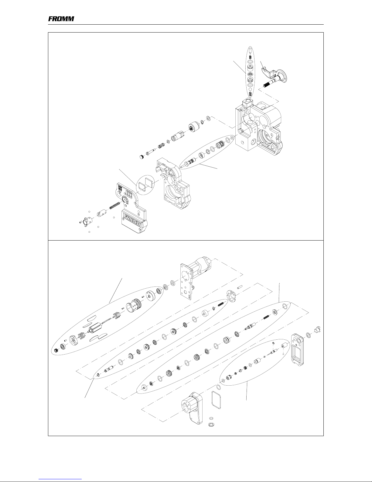
TECHNICAL DETAILS
1-6
5 Welding valve
2 Tension force control valve
4 Exhaust silencer
b Valve lever for welding
8 Welding motor
6 Welding motor valve
9 Turn off valve
7 Welding time valve
CONVERSION PARTS
1-7
1.2 CONVERSION PARTS
When changing strap thickness or strap width following parts must be exchanged.
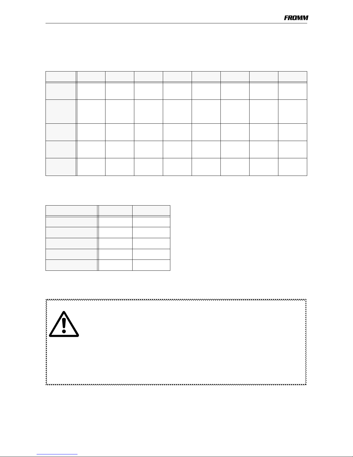
1.2.1 Conversion parts: strap width
1.2.2 Conversion parts: strap thickness
10mm 11.1mm 12mm 12.7mm 13mm 15mm 15.5mm 16mm
Guide
pin P30.1156 P30.1158 P30.1156 P30.1157 P30.1158 P30.1159 P30.1160 P30.1161
Guide
pin P30.1162 P30.1164 P30.1162 P30.1163 P30.1164 P30.1165 P30.1166 P30.1167
Guide
case P32.1205 P32.1205 P32.1206 P32.1206 P32.1206 P32.1206 P32.1206 P32.1206
Strap
stop P32.1230 P32.1231 P32.1232 P32.1233 P32.1234 P32.1235 P32.1236 P32.1237
Strap
guide P32.1239 P32.1240 P32.1241 P32.1242 P32.1243 P32.1244 P32.1245 P32.1246
0.4-0.64mm 0.65-1.05mm
Steel insert P32.1201 P32.1202
Tensioning wheel P32.1219 P32.1220
Gripper P32.1222 P32.1225
Gripper P32.1223 P32.1226
Gripper P32.1224 P32.1227
Attention!
When converting tools always change the item number on the ty pe label
Replace following parts:
Type label N41.9143
2 x hammer head bolts N2.4902
Enclose the suitable operation manual with the tool after each conversion
(see paragraph Ordering manuals)
PERIODIC MAINTENANCE AND CONTROL
1-8
1.3 PERIODIC MAINTENANCE AND CONTROL
Carry out 12- months cycles doing one shift work. Doing multiple shift work respectively more often.
1.3.1 Procedure
Before using check tool for following possible faults:
• Visual test of the tool for loose, lost or damaged parts
• Clean all dirty parts of the tool, especially strap abrasion in the tensioning or the welding unit by
using compressed air. (Never use any hard tools like a wire brush or a screw driver for cleaning)
• Condition of the tensioning wheel, the welding grippers and the tensioning grippers
Connect tool to the air supply and perform a test strapping.
Check the following:
• Tightness of the pneumatic system
• Strap guidance
• Strap feed and strap tensioning
• Tensioning force adjustment (see operation manual P355)
• Cutting of the upper strap
• Welding time adjustment (see operation manual P355)
• Welding pressure adjustment (see operation manual P355)
• Seal quality (see operation manual P355)
Proceed according to paragraph „Troubleshooting“ after a fault appears.
Attention!
Before maintenance always remove the tool from the compressed air supply.
For exchange of wearing parts see operation manual P355
Never use water or solvents for cleaning the tool’s surface.
PERIODIC MAINTENANCE AND CONTROL
1-9
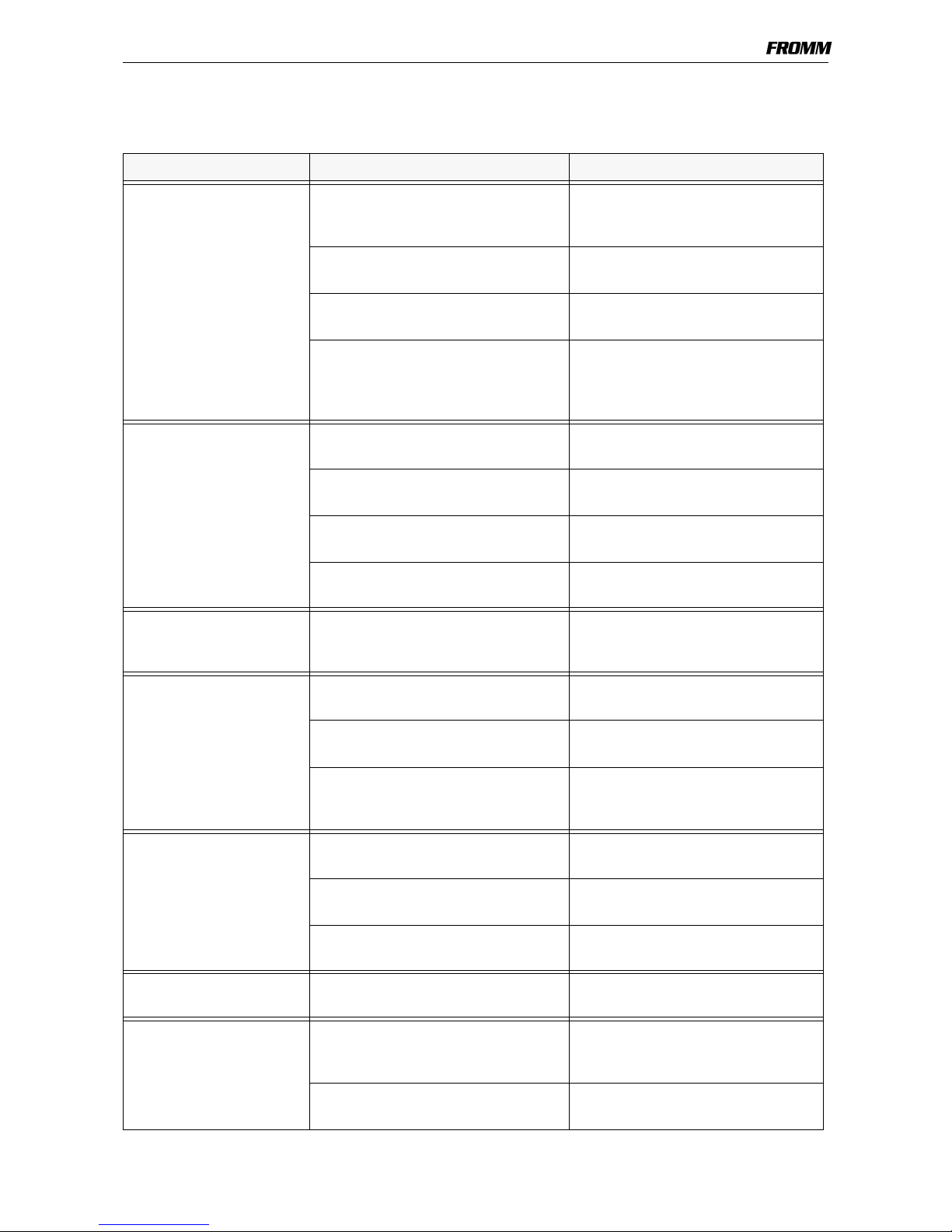
1.3.2 Troubleshooting
A sufficient compressed air supply and the use of the tool’ s specific strap should be guaranteed before
each tool repair.
SYMPTOM CAUSE REMEDY
Tool doesn’t tension,
Tensioning motor runs
The tensioning wheel is packed with
strap residue or is worn and mills on
the strap
Clean tensioning wheel with
compressed air or replace it
Wrong tensioning wheel or tensioning
wheel is assembled reversed
Correct assembling or use the correct
tensioning wheel.
Grippers are dirty, worn or wrongly
assembled
Replace grippers, clean them with
compressed air or assemble correctly
Gearing parts from the tensioning gear
are defective
Loose pinion P32.1123 on tensioning
motor
Check tensioning gear and replace
defect parts
Tensioning motor doesn’t
run
Tensioning motor defective Check component parts and replace
damaged ones
Tensioning gear defective Check component parts and replace
damaged ones
Pneumatic control system is defective Check component parts and replace
damaged ones
Needle free wheeling assembled
reversed
Assemble correctly
Tensioning wheel turns
back immediately after the
tensioning cycle
Defective needle free wheeling
N3.4509
Check and replace if necessary
Tool doesn’t weld,
welding motor runs
Welding gripper is dirty or worn Clean and check welding gripper and
replace damaged one
Welding stop gripper is dirty or worn Clean and check welding stop gripper
and replace damaged one
Pinion P32.1023 lose at the motor or
welding eccentric, resp. The journal at
the welding eccentric is broken off.
Check component parts and replace
damaged ones
Welding motor doesn’t run Welding motor defective Check component parts and replace
damaged ones
Welding mechanism defective Check component parts and replace
damaged ones
Pneumatic control system is defective Check component parts and replace
damaged ones
Gear noise Tensioning or welding gear is worn Check component parts and replace
damaged ones
Welding motor does not
stop
Turn off valve or welding motor valve
jam, resp. the welding time valve is
blocked.
Check and clean parts, exchange
damaged parts
Diameter of the air supply hose is too
small.
Install air supply hose with a minimum
inner diameter of 9mm (3/8")

PERIODIC MAINTENANCE AND CONTROL
1-10
1.3.3 Checklist
Carry out several test strappings and check the following items.
• Connect the tool to the compressed air supply and check if air escapes
• Insertion of the strap
• Strap guidance
• Strap feed and strap tension
• Tension force adjustment (see operation manual P355)
• Cutting of the upper strap
• Welding time adjustment (see operation manual P355)
• Seal quality (see operation manual P355)
• Type label
Tool badly cuts the strap or
doesn’t cut at all
Cutter is worn or damaged Replace cutter
Wrong adjustment of the coupler
P32.1250
Check adjustment and readjust if
necessary
(see operation manual P355)
Welding gripper is worn Replace welding gripper
Welding time too short Change adjustment
(see operation manual P355)
Defective pressure spring N2.5237 Replace pressure spring
Welding time not
adjustable
Welding time valve dirty or damaged Clean and check component parts
and replace damaged ones
Tensioning force not
adjustable
Tension force control valve dirty or
damaged
Clean and check component parts
and replace damaged ones
SYMPTOM CAUSE REMEDY
PERIODIC MAINTENANCE AND CONTROL
1-11
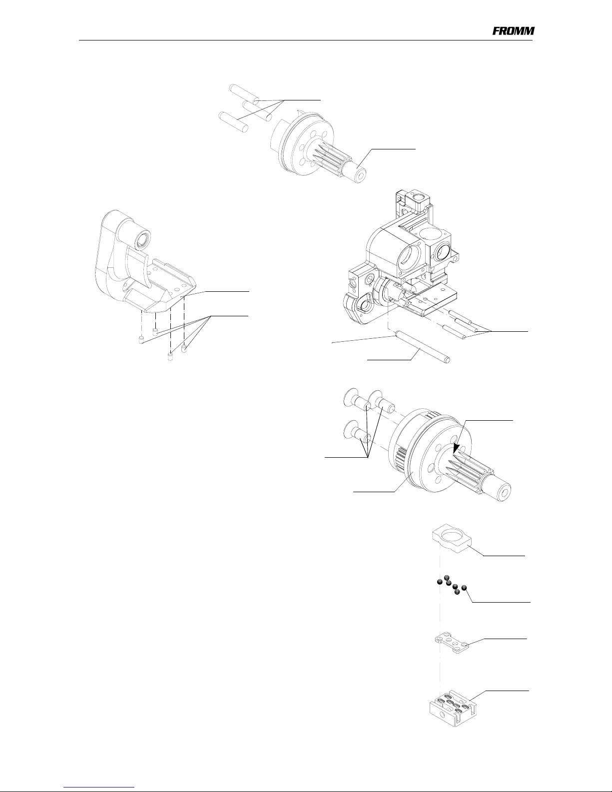
1.3.4 Glueing rules
Following parts have to be glued with LOCTITE 603:
Additional the screws N1.2112 have to be glued in the
planetary gear stage P32.0118 using LOCTITE 222.
Don’t clamp the planet shaft directly on the teeth when
loosening or tightening the screws N1.2112.
1.3.5 Lubrication rules
All bearing parts of the welding unit have to be cleaned and
lubricated with Klueber Isoflex Alltime SL2 grease during each
maintenance.
Lubrication interval:
At each maintenance or after 12 months at the latest.
Planet shaft P32.1044
with the parallel pins N2.2145.
Tensioning body P32.1254
with the parallel pins N2.2189
Body P35.2002 with
swivel shaft P35.2004
and parallel pins N2.2188
P35.2004
N2.2188
Press in measure see
P32.1044
N2.2145
P32.1254
N2.2189
„Assembly information“
Clamp here
P32.0118
N1.2112
Bearing
welding unit
P32.1029
N3.1702 (6X)
P32.1027
P32.1053
PERIODIC MAINTENANCE AND CONTROL
1-12
All movable gear parts have to be lubricated with MOLYKOTE BR 2 PLUS grease.
Lubrication interval: At each maintenance or after 12 months at the latest.
All other parts have to be greased according to the explosion drawing.
Lubrication interval: At each maintenance or after 12 months at the latest.
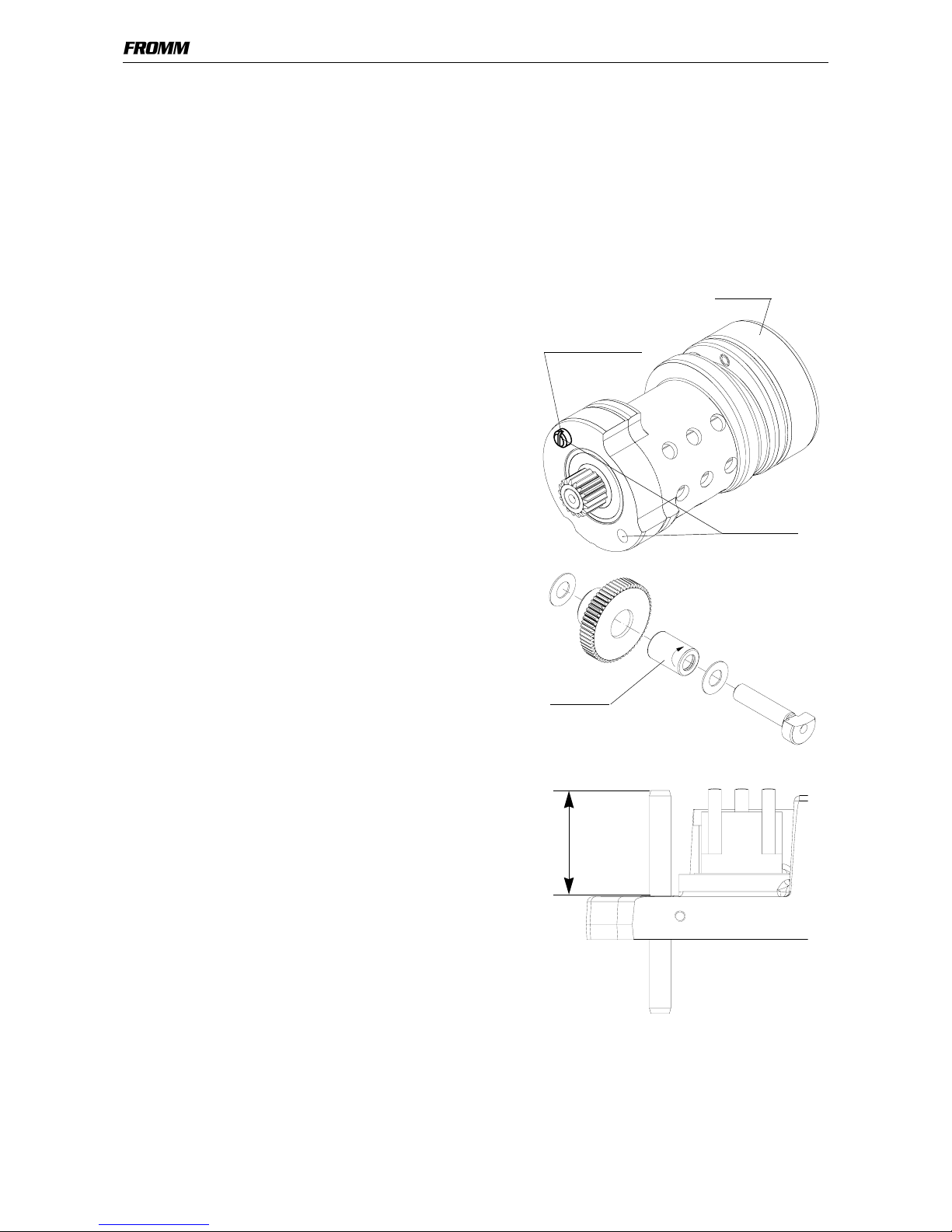
1.3.6 Assembly information
Air motors
Installation:
When installing the air motors pay attention to the correct
position of the position screw.
(see picture)
Removing welding motor:
- Remove positioning screw and screw in two screws
M4 (e.g. N1.1936) in the two existing thread holes.
- Pull out welding motor.
Needle free wheeling:
Pay attention to the assembling direction of the needle
free wheeling N3.4509.
The sense of rotation is stamped in the front of the free
wheeling.
Swivel shaft:
When pressing in the swivel shaft P35.2004 the
dimension 39.2 mm must be observed (see drawing)
Position screw
Thread M4
Air motor
N3.4509
39.2 mm
PERIODIC MAINTENANCE AND CONTROL
1-13
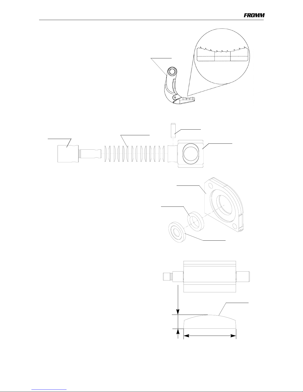
Grippers:
When installing the grippers into the tensioning
body P32.1254 pay attention to the direction of
the teeth.(see picture)
Cup springs:
Assemble the cup springs N2.5621 as shown in the picture.
Motor cover:
When assembling the motor cover P35.2028, pay
attention to the assembling direction of the spring
P35.2026 and the thrust piece P35.2027. (See drawing)
Attach parts with grease (ESSO BEACON 2) !
The same assembling position is valid for the
welding motor too!
Vane:
If the minimum diameters (see drawing) are not
reached anymore, the vanes P35.2024 must be
exchanged.
P32.1254
Grippers
N2.5621(14X)
N2.2443
P32.1031
P32.1030
P35.2028
P35.2026
P35.2027
min. 8.2 mm
min. 37.2 mm
P35.2024
RECOMMENDED SPARE PARTS
1-14
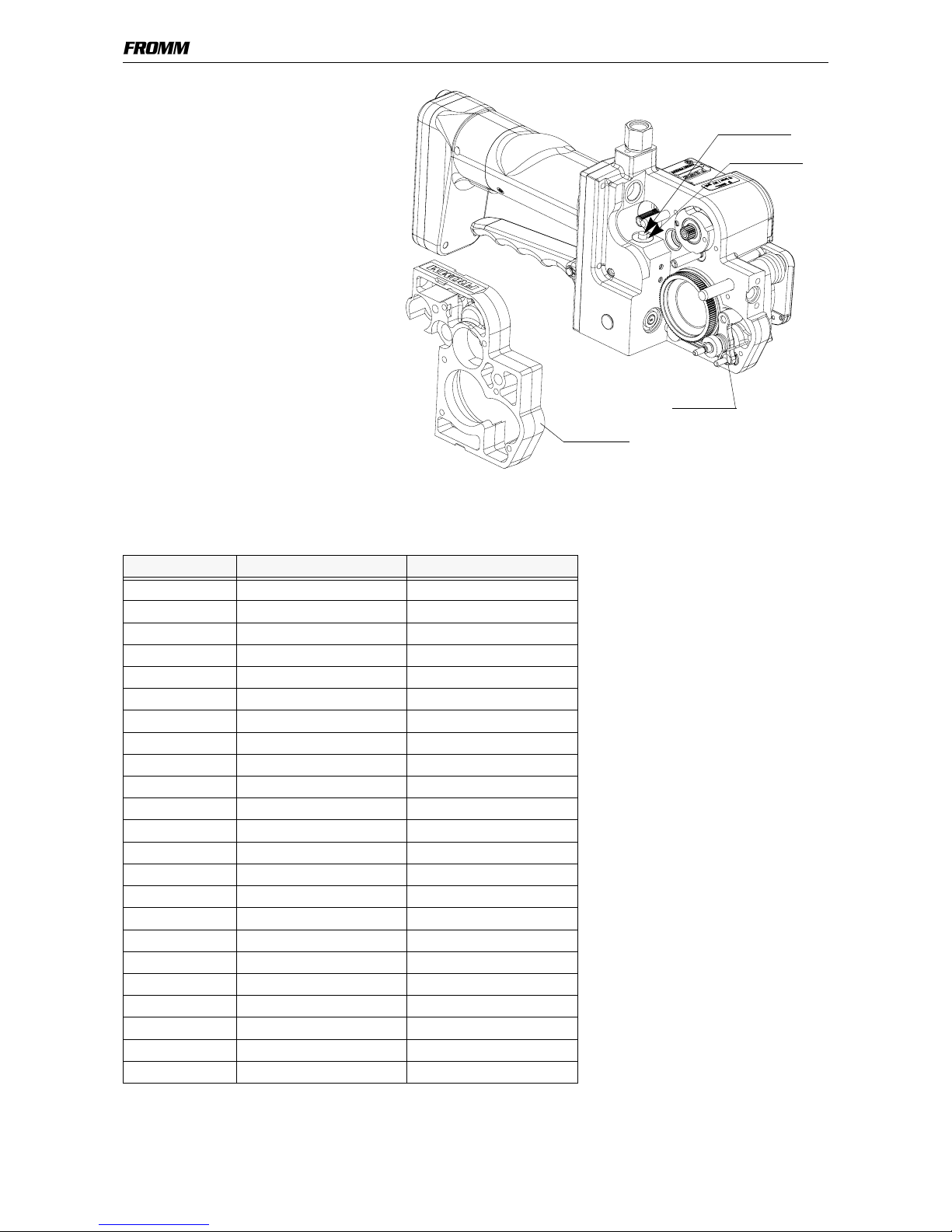
Gear body:
When assembling or disassembling the
gear body (P35.2034) the touch bolt
(P35.2007) and the guide (P35.2006) of
the welding valve must be pressed down.
The spring N2.5822 must be slightly lifted
up. (see drawing)
1.4 RECOMMENDED SPARE PARTS
Following spare parts are recommended for stock keeping:
Besides should be stocked the wearing parts of the different Types.
Stock only parts from tools that are in sale.
Item-No. Description Pieces per tool
N1.1305 Screw 2
N1.1813 Screw 6
N1.1820 Screw 1
N1.1904 Screw 5
N1.1909 Flat head screw 2
N1.1915 Screw 2
N1.1929 Screw 1
N1.1932 Flat head screw 2
N1.1935 Flat head screw 4
N1.1936 Flat head screw 2
N1.6205 Spring lock washer 2
N1.6503 Safety washer 6
N1.6504 Safety washer 9
N1.6505 Safety washer 4
N2.1107 Security ring 1
N2.1118 Security ring 1
N2.1121 Security ring 5
N3.1174 Ball bearing 2
N3.1702 Ball 6
N3.1703 Ball 1
N5.2702 Cover 2
P32.1034 Lever 1
P32.0110 End cover 1
P35.2007
P35.2034
N2.5822
P35.2006

ACCESSORY TOOLS
1-15
1.5 ACCESSORY TOOLS
*These tools are also included in the P320 tool set.
**These tools are also included in the P300 tool set.
Item
number
Field Use
N7.3219 ** F10 Press in and press out pressure pad for N3.3173/P35.2002
N71.3235 * F5 Press in and press out arbor for N3.4509/P35.2036
N71.3237 * F3 Press in and press out arbor for N3.1159/P32.1037
N71.3238 * F3 Press in and press out pressure pad for N3.1159/P32.1037
N71.3239 * F7 Press in arbor for N3.2347/P32.1024
N71.3240 * F7 Press out arbor for N3.2347/P32.1024
N71.3241 * F7 Press in and press out pressure pad for N3.2347/P32.1024
N71.3242 * F8 Press in and press out arbor for N3.2346/P32.1238
N71.3243 * F6 Press in arbor for N3.1134, P32.1023/P32.1022
N71.3244 * F6, F9 Press out arbor for N3.1134, P32.1023/P32.1022; P35.0123/P32.1123;
P35.0124/P32.1023
N71.3245 * F6, F8 Pressure pad for N3.1134, P32.1023/P32.1022; N3.2346/P32.1238
N71.3246 * F1 Press in and press out arbor for N3.1157/P32.1044
N71.3247 * F1 Press in and press out pressure pad for N3.1157/P32.1044
N71.3248 * F4 Press in arbor for N3.3172/P32.1254
N71.3249 * F4 Press out pressure pad for N3.3172/P32.1254
N71.3250 * F2, F4 Press in and press out arbor for N3.3172/P35.2002; N3.3172/P32.1254
N71.3253 * F10 Press in and press out arbor for N3.3173/P35.2002
N71.3254 * F10, F9 Press out arbor for N3.3173/P35.2002; Press on arbor for P32.1123/
P35.0123 and P32.1023/P35.0124
N71.3273 F5 Press in and press out pressure pad for N3.4509/P35.2036
N71.3274 F12 Hook for exhaust ring P35.2005/P35.2002
N71.3275 F9 Press on pressure pad for P32.1123/P35.0123, P32.1023/P35.0124
N71.3276 F11 Pressure pad for P35.2021/P35.2023, N3.1174
N71.3277 F11 Thrust piece for P35.2021/P35.2023, N3.1174
N71.3280 F9 Press out pressure pad for P32.1123/P35.0123, P32.1023/P35.0124
ACCESSORY TOOLS
1-16
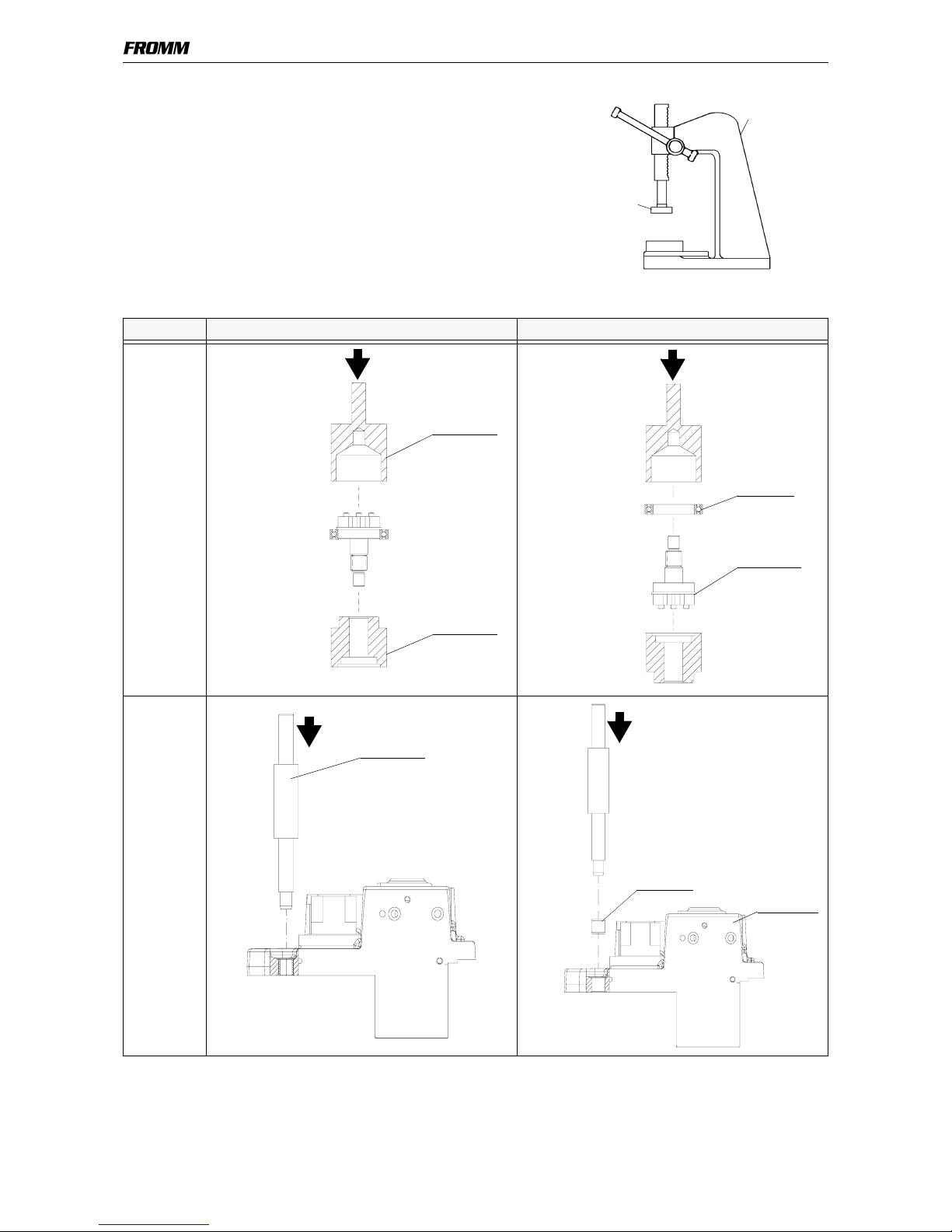
1.5.1 Use of accessory tools
Accessory tools should only be used with the suitable arbor press
N7.5108 in order to avoid a tilt of the pressed in parts.
Additional a retainer (N7.3215) is necessary.
Part Disassembly Assembly
N3.1157/
P32.1044
F1
N3.3172/
P35.2002
F2
N7.5108
N7.3215
N71.3246
N71.3247
N3.1157
P32.1044
N71.3250
N3.3172
P35.2002
ACCESSORY TOOLS
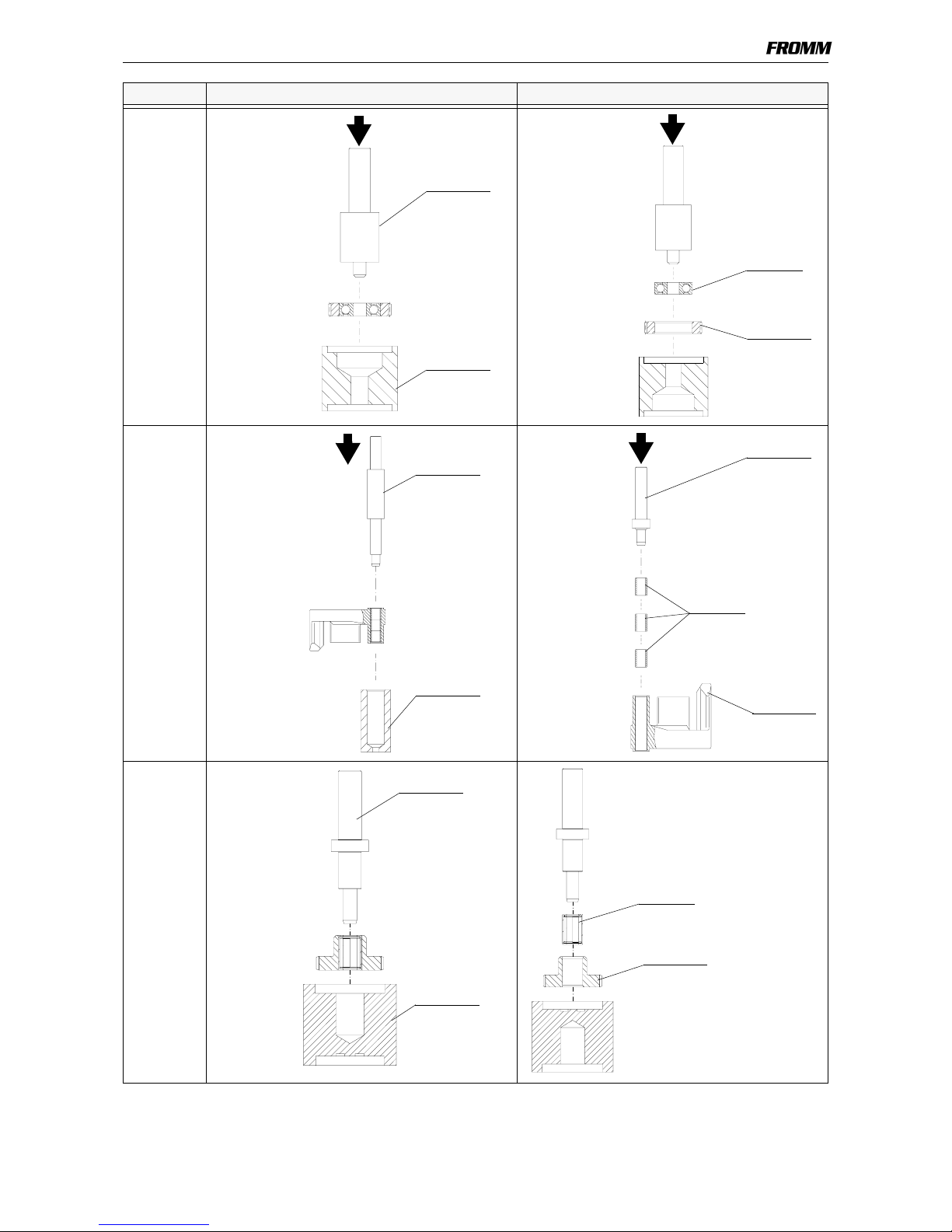
1-17
N3.1159/
P32.1037
F3
N3.3172/
P32.1254
F4
N3.4509/
P35.2036
F5
Part Disassembly Assembly
N71.3237
N71.3238
N3.1159
P32.1037
N71.3250
N71.3249
N71.3248
N3.3172
P32.1254
A
A
N71.3235
N71.3273
N3.4509*
P35.2036
*Assembling position
see „Assembly information“
 Loading...