

Fromm P328 M, P328, P328 HA, P328 A, P329 M/HA Service Manual
...
SERVICE MANUAL
BATTERY - POWERED
PLASTIC STRAPPING TOOL
MODEL
P328 M/HA / P328 A/A
P328.sen.fm/MAS/© 02.16
Manual for authorized dealers and service points
Purchase at Allstrap (866) 779-2673

1. SERVICE MANUAL P328 M/HA / P328 A/A
2. DRAWINGS P328 M/HA / P328 A/A
3. SPARE PARTS LISTS P328 M/HA / P328 A/A
Type i ndep e nden t spare parts
Type d epen dent spa re parts
4. MANUAL P328 M/HA
Techn ical Data
Chart of Types
Exchange of wearing parts
5. MANUAL P328 A/A
Techn ical Data
Chart of Types
Exchange of wearing parts
6. SERVICE MANUAL P329 M/HA / P329 A/A
7. DRAWINGS P329 M/HA / P329 A/A
8. SPARE PARTS LISTS P329 M/HA / P329 A/A
Type i ndep e nden t spare parts
Type d epen dent spa re parts
9. MANUAL P329 M/HA
Techn ical Data
Chart of Types
Exchange of wearing parts
10. MANUAL P329 A/A
Techn ical Data
Chart of Types
Exchange of wearing parts
11. NEWS
12. NOTES

1-2
INDEX PAGE
1.1 ACCESSORIES 1-3
1.1.1 Battery . . . . . . . . . . . . . . . . . . . . . . . . . . . . . . . . . . . . . . . . . . . . . . . . . . . . . . . 1-3
1.1.2 Battery chargers . . . . . . . . . . . . . . . . . . . . . . . . . . . . . . . . . . . . . . . . . . . . . . . 1-3
1.1.3 Battery tester . . . . . . . . . . . . . . . . . . . . . . . . . . . . . . . . . . . . . . . . . . . . . . . . . . 1-3
1.1.4 Memory reader for circuit board . . . . . . . . . . . . . . . . . . . . . . . . . . . . . . . . . . . 1-3
1.1.5 Suspension . . . . . . . . . . . . . . . . . . . . . . . . . . . . . . . . . . . . . . . . . . . . . . . . . . . 1-3
1.1.6 Fan . . . . . . . . . . . . . . . . . . . . . . . . . . . . . . . . . . . . . . . . . . . . . . . . . . . . . . . . . 1-4
1.2 TECHNICAL DETAILS 1-4
1.2.1 Strap tension . . . . . . . . . . . . . . . . . . . . . . . . . . . . . . . . . . . . . . . . . . . . . . . . . . 1-4
1.2.2 Electric schematic Semi Automatic ELS.1082 . . . . . . . . . . . . . . . . . . . . . . . . 1-5
1.2.3 Connecting plan Semi Automatic . . . . . . . . . . . . . . . . . . . . . . . . . . . . . . . . . . 1-5
1.2.4 Electric schematic Automatic ELS.1083 . . . . . . . . . . . . . . . . . . . . . . . . . . . . . 1-6
1.2.5 Connecting plan Automatic . . . . . . . . . . . . . . . . . . . . . . . . . . . . . . . . . . . . . . . 1-6
1.3 CONVERSION PARTS P328 1-7
1.4 PERIODIC MAINTENANCE AND CONTROL 1-8
1.4.1 Procedure . . . . . . . . . . . . . . . . . . . . . . . . . . . . . . . . . . . . . . . . . . . . . . . . . . . . 1-8
1.4.2 Troubleshooting. . . . . . . . . . . . . . . . . . . . . . . . . . . . . . . . . . . . . . . . . . . . . . . . 1-9
1.4.3 Battery test . . . . . . . . . . . . . . . . . . . . . . . . . . . . . . . . . . . . . . . . . . . . . . . . . . 1-11
1.4.4 Checklist . . . . . . . . . . . . . . . . . . . . . . . . . . . . . . . . . . . . . . . . . . . . . . . . . . . . 1-11
1.4.5 Lubrication rules . . . . . . . . . . . . . . . . . . . . . . . . . . . . . . . . . . . . . . . . . . . . . . 1-11
1.4.6 Glueing rules . . . . . . . . . . . . . . . . . . . . . . . . . . . . . . . . . . . . . . . . . . . . . . . . 1-12
1.4.7 Assembly information . . . . . . . . . . . . . . . . . . . . . . . . . . . . . . . . . . . . . . . . . . 1-13
1.5 RECOMMENDED SPARE PARTS 1-20
1.6 MAINTENANCE PLAN P328 1-21
1.7 ACCESSORY TOOLS 1-22
1.8 USE OF ACCESSORY TOOLS 1-23
1.9 ORDERING SPARE PARTS 1-29
1.9.1 Ordering manuals . . . . . . . . . . . . . . . . . . . . . . . . . . . . . . . . . . . . . . . . . . . . . 1-29
1.9.2 Ordering address. . . . . . . . . . . . . . . . . . . . . . . . . . . . . . . . . . . . . . . . . . . . . . 1-29
1.9.3 Finding out of the tool type (item number), the serial number
and the version number: . . . . . . . . . . . . . . . . . . . . . . . . . . . . . . . . . . . . . . . . 1-30
1.10 SERVICE ADDRESS 1-30
1.11 CHART OF TYPES 1-30
1.11.1 Chart of types P328 M / HA . . . . . . . . . . . . . . . . . . . . . . . . . . . . . . . . . . . . . 1-30
1.11.2 Chart of types P328 A / A . . . . . . . . . . . . . . . . . . . . . . . . . . . . . . . . . . . . . . . 1-30
Purchase at Allstrap (866) 779-2673
1-3
1.1 ACCESSORIES
1.1.1 Battery
Use only original Fromm batteries N5.4349 (Li-Ion).
1.1.2 Battery chargers
The battery charger must be ordered separately according to the table mentioned below.
(..) = an adaptor N52.2102 is required.
1.1.3 Battery tester
Information to the Battery tester you will get by FROMM System GmbH.
(see 1.10 SERVICE ADDRESS)
1.1.4 Memory reader for circuit board
To r e ad th e m e mo ry in f or m at i on o f t h e t oo l s ci r cu it bo a rd th e r e ad e r N 7. 5 15 4 c an be or d er e d.
With this the following data could be read:
• software version
•date of software
• strapping cycles
• calibration current
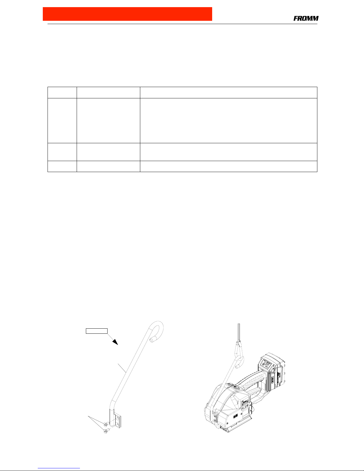
1.1.5 Suspension
When working stationary the strapping tool can be suspended at a spring loaded balancer by using a
suspension bracket.
For working in normal position a stiff suspension bracket with screws and washers can be ordered under item
number P32.0231.
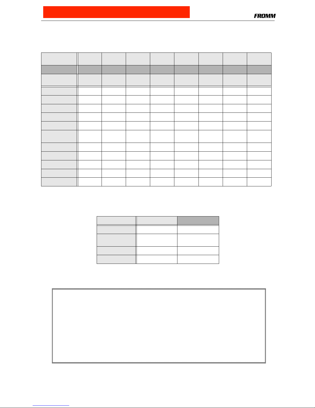
Item-No. Voltage / frequency Admitted for country
N5.4443 220 - 240V / 50 - 60Hz A, B, BG, BIH, BOL, BR, BY, CH, CL, CZ, D, DK, DZ, E, EAS, EST,
ET, F, FIN, GE, GR, H, HK, HR, I, IL, IND, IR, IRQ, IS, JOR, KSA,
KWT, L, LAR, LT, LV, MA, MC, MK, MOC, N, NL, P, PK, PE, PL, PRC,
PY, RA, RCH, RI, RL, RO, ROK, ROU, RP, RUS, S, SK, SLO, SYR,
THA, TN, TR, UA, (UAE), YU, YV, (BRN), (BRU), (CY), (EAK), (EAT),
(GB), (IRL), (M), (MAL), (OM), (SGP), (Y), (Z), (ZA), (ZW)
N5.4447 120V / 50 - 60Hz BR, C, CDN, CO, CR, DOM, EC, GCA, J, JA, KSA, LB, MEX, NIC,
PA, Puerto Rico, RC, RP, USA, YV
N5.4445 220 - 240V / 50 - 60Hz AUS, NZ
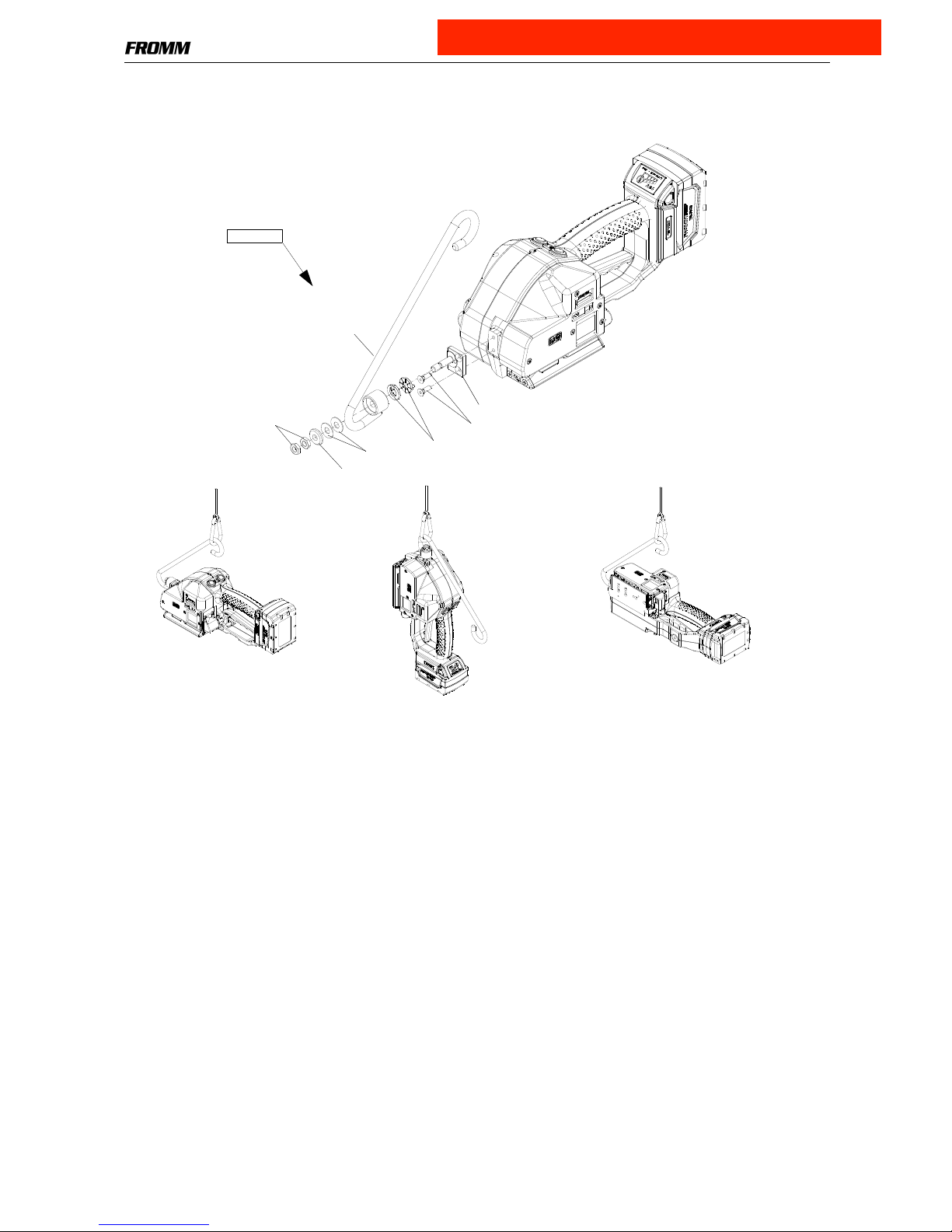
P32.0231
P32.8313
N1.2163
Purchase at Allstrap (866) 779-2673
1-4
For working in alternating positions a turnable suspension bracket with screws and washers can be ordered
under item number P32.0223.
1.1.6 Fan
In order to avoid overheating of the motor we recommend at environmental temperatures above 40°C / 104°F
using the optional fan P32.0228.
(see 1.4.7 Assembly information)
1.2 TECHNICAL DETAILS
1.2.1 Strap tension
The tension force values mentioned in the operation manual (250-2600N) are not achievable with each strap.
They depend on following factors:
•Hardness of the package,
the maximum tension force values are achievable with hard packages.
•Elongation and creep properties of the plastic strap,
the maximum tension force values are achievable by using plastic straps with a low elongation.
•Surface quality of the plastic strap,
the maximum tension force values are achievable with waxed and embossed straps.
•Strap width, strap thickness,
the maximum tension force values are achievable with thick and wide straps.
P32.0223
N1.5105
N2.5623
P35.2073
P32.8302
P35.2069
N1.2163
Mobilux EP2
P32.8301
Purchase at Allstrap (866) 779-2673
1-5
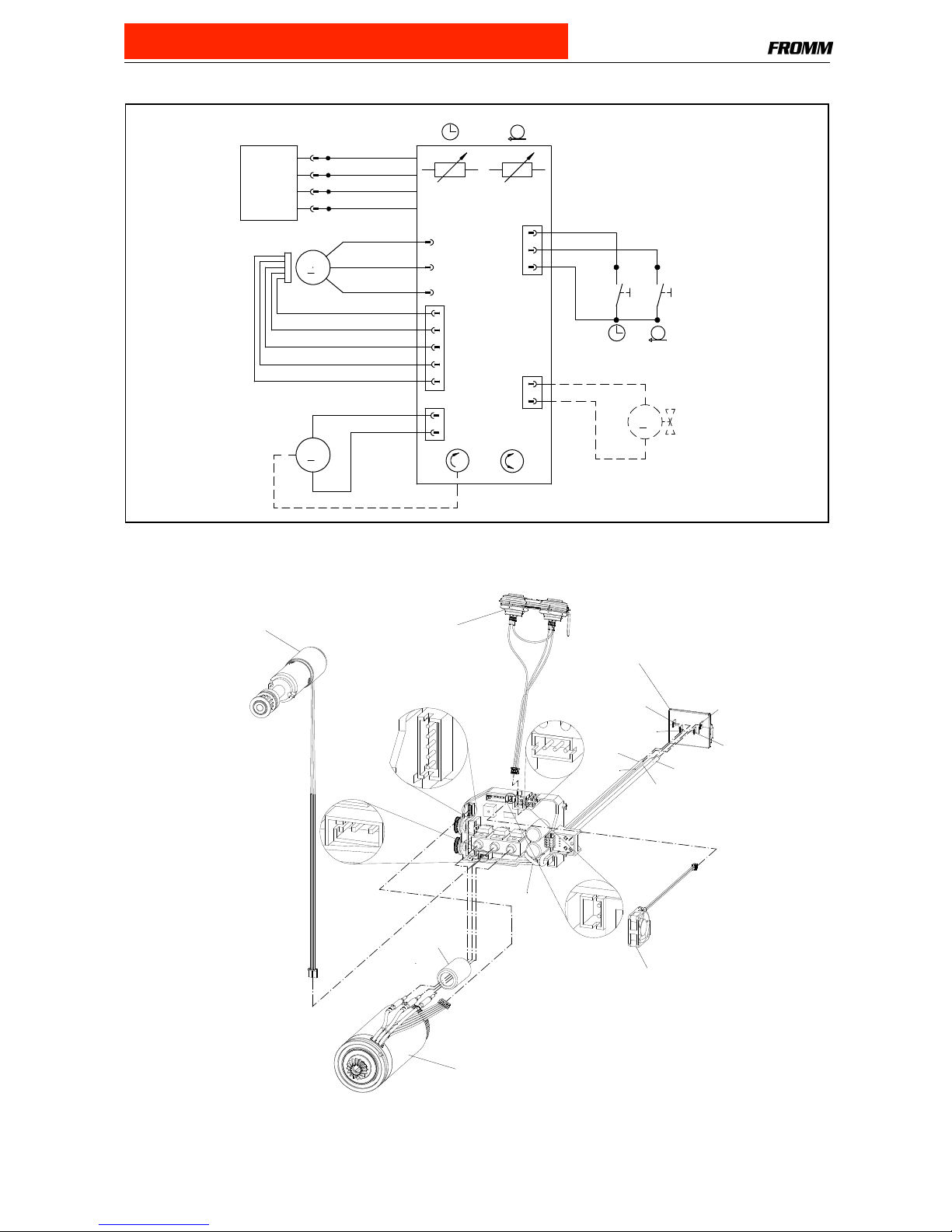
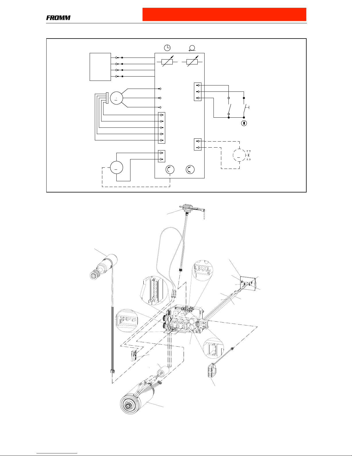
1.2.2 Electric schematic Semi Automatic ELS.1082
1.2.3 Connecting plan Semi Automatic
18VDC
red
-
+
red
2
1
UB
M3
2
1
3
red
blue
1
2
(-)
(+)
M2
U
V
W
yellow
violett
brown
Hall3
Hall2
Hall1
GND
+5V
5
4
3
2
1
M1
2
1black
red
(+)
(-)
optional Fan
blackblack
black
DC
DP
2
1
HA
M
Manual / 1/2 Auto
P32.8150
N51.1127
P32.0213
P32.0228 (optional)
P33.2155
N51.2194
red
red
black
blue
red
blue
black
red
P32.8148
Purchase at Allstrap (866) 779-2673
1-6
1.2.4 Electric schematic Automatic ELS.1083
1.2.5 Connecting plan Automatic
18VDC
red
-
+
red
2
1
UB
M3
2
1
3
red
blue
1
2
(-)
(+)
M2
U
V
W
yellow
violett
brown
Hall3
Hall2
Hall1
GND
+5V
5
4
3
2
1
M1
2
1black
red
(+)
(-)
A
A
Auto / Auto
1(C)
4(N0)
optional Fan
blackblack
black
DC
DP
P32.8154
N51.1127
P32.0213
P32.0228 (optional)
P33.2155
N51.2194
red
red
black
blue
red
blue
black
red
P32.8151
N5.2382
Purchase at Allstrap (866) 779-2673
1-7
1.3 CONVERSION PARTS P328
Conversion parts for changing of strap width and strap thickness
Conversion parts from Semi automatic to Automatic
Semi
automatic
43.2422 43.2423 43.2424 43.2432 43.2453 43.2454 43.2461 43.2462
Automatic
43.2622 43.2623 43.2624 43.2632 43.2653 43.2654 43.2661 43.2662
12 x
0.65-1.05
12.7 x
0.4-0.64
12.7 x
0.65-1.05
13 x
0.65-1.05
15.5 x
0.4-0.64
15.5 x
0.65-1.05
16 x
0.4-0.64
16 x
0.65-1.05
Guide pin
P32.8182 P32.8183 P32.8183 P32.8185 P32.8186 P32.8186 P35.3216 P35.3216
Guide pin
P32.8181 P32.8191 P32.8191 P32.8193 P32.8194 P32.8194 P35.3217 P35.3217
Guide case
P32.8179 P32.8179 P32.8179 P32.8179 P35.3215 P35.3215 P35.3215 P35.3215
Strap stop
P32.8162 P32.8163 P32.8163 P32.8164 P32.8166 P32.8166 P32.8167 P32.8167
Strap guide
P32.8172 P32.8173 P32.8173 P32.8174 P32.8176 P32.8176 P32.8177 P32.8177
Ten si oni ng
wheel
P35.3203 P35.3202 P35.3203 P35.3203 P35.3202 P35.3203 P35.3202 P35.3203
Gripper
P32.8109 P32.8112 P32.8109 P32.8109 P32.8112 P32.8109 P32.8112 P32.8109
Gripper
P32.8110 P32.8113 P32.8110 P32.8110 P32.8113 P32.8110 P32.8113 P32.8110
Gripper
P32.8111 P32.8114 P32.8111 P32.8111 P32.8114 P32.8111 P32.8114 P32.8111
Cutter
P35.3214 P32.8197 P35.3214 P35.3214 P35.3214 P35.3214 P35.3214 P35.3214
Insertation part
-- P32.8198 -- -- P32.8198 -- P32.8198 --
Semi automatic Automatic
Circuit board
P32.8148 P32.8151
Tou ch con tac t-
switch
P32.8150 P32.8154
Pusher
-- P32.8133
Adhesive label
N44.9160 N44.9170
Attention!
When converting tools always change the item number on the type label.
Replace following parts:
Type label N44.9122
2 x hammer head bolts N2.4902
Enclose the suitable operation manual with the tool after each conversion
(see paragraph 1.9.1 Ordering manuals).
Purchase at Allstrap (866) 779-2673
1-8
1.4 PERIODIC MAINTENANCE AND CONTROL
(Carry out 12- months cycles doing one shift work. Doing more shift work respectively more often.)
To a v o i d d a m ages o n t h e mo t o r sha ft the t wo n e edle free wheelings N3.4509 and N3.4520 have to be
replaced after 80 000 strapping cycles.
1.4.1 Procedure
Before using check tool for following possible faults:
•Visual test of the tool for loose, lost or damaged parts
•Clean all dirty parts of the tool, especially strap abrasion in the tensioning or the welding unit by
using compressed air. (Never use any hard tools like a wire brush or a screw driver for cleaning)
Carry out a test strapping and check following:
•Insertion of the strap
•Strap feed and strap tensioning
•Tensioning force adjustment (see operation manual P328)
•Cutting of the upper strap
•Welding time adjustment (see operation manual P328)
• Seal quality (see operation manual P328)
•Function of the LED - display
Proceed according to paragraph 1.4.2 after a fault appears.
For exchange of wearing parts see operation manual P328.
Attention!
Remove battery from tool before each maintenance work.
Never use water or solvents for cleaning the tool’s surface.
Purchase at Allstrap (866) 779-2673
1-9
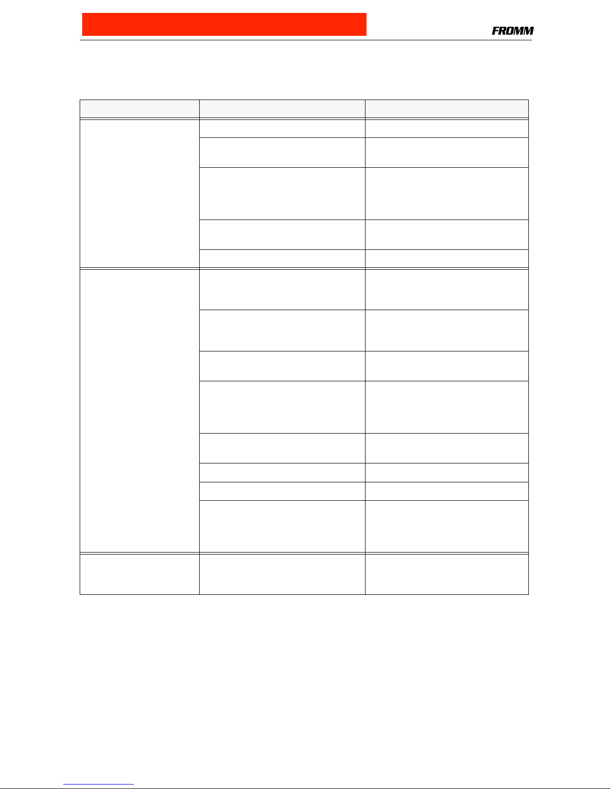
1.4.2 Troubleshooting
Ensure before each tool repair that the battery is charged and
the tool’s specific strap is used
SYMPTOM CAUSE REMEDY
To ol d oe sn ’t w or k at a ll B at t er y is e mpty or defective Charge or replace battery
Contact problems caused by a broken
battery housing
Replace battery
Contact problems caused by a
damaged insertation part N51.2194 or
damaged motor housings P32.8103
and P32.8105/96
Replace insertation part or
motor housing
Contact problem of the internal wires Check contacts and fix them if
required or change defective parts
Defective circuit board Replace circuit board
To ol do e sn ’ t t en si o n Te ns i on i ng wh e el is d i rt y o r w o rn C l ea n t e ns i on i ng wh e el or r e pl a ce it ,
don’t use any hard objects for this
(see operation manual P328)
P32.8128 is not meshing with
P32.8130 because spring N2.5296 is
defective or parts are dirty
Replace spring N2.5296,
clean dirty parts
Faulty tensioning wheel or tensioning
wheel is assembled reversed
Correct assembling
(see operation manual P328)
Grippers are dirty, worn or wrongly
assembled
Replace grippers, clean them or
assemble correct,
don’t use any hard objects for this
(see operation manual P328)
Gearing parts from the tensioning gear
are defective
Check tensioning gear and replace
defective parts
Defective circuit board Replace circuit board
Defective gear bearings Replace bearings
Needle free wheeling N3.4509 in gear
wheel P32.8139 or N3.4520 in conical
gear wheel P32.8138 assembled
reversed or defective
Assemble the needle free wheeling
correct or replace it
Te ns i on i ng wh e el tu rn s
back immediately after the
tensioning cycle
Defective needle free wheeling
N3.4509 in P32.8134
Check parts and replace if necessary
Purchase at Allstrap (866) 779-2673
1-10
To ol do e sn ’ t w el d We l di n g g ri p pe r P 32 . 15 11 is di r ty or
worn
Replace or clean welding gripper,
don’t use any hard objects for this
(see operation manual P328)
Welding stop gripper P32.8107 is dirty
or worn
Replace or clean welding stop gripper,
don’t use any hard objects for this
(see operation manual P328)
Damaged housing parts Replace housing parts
Defective circuit board Replace circuit board
Pressure spring N21.5138 defective Replace pressure spring
Needle free wheeling N3.4509 in
P32.8139 defective or assembled
reversed
Assemble the needle free wheeling
correct or replace it
Gearing parts of the welding gear are
defective
Check welding gear and replace
defective parts
Gear motor N51.1127 defective Replace Gear motor
To ot he d be lt N 4. 3 23 6 or To ot he d be lt
pulley P32.8122 is worn
Replace Toothed belt or
To ot h ed be l t p ul le y
Defective gear bearing Replace bearing
Tool badly cuts the strap or
doesn’t cut at all
Cutter is worn or damaged Replace cutter
(see operation manual P328)
Wrong adjustment of the coupler
P35.0146
Check adjustment and readjust if
necessary
(see operation manual P328)
Welding gripper P32.1511 is worn Replace welding gripper
(see operation manual P328)
Welding time too short Change adjustment
(see operation manual P328)
Defective pressure spring N2.5237 Replace pressure spring
Tool switches off after a few
strappings
(Displaying empty battery)
Battery defective or empty Check the battery and change
defective batteries
Gear noise Tensioning or welding gear is worn Check component parts and replace
defective ones
SYMPTOM CAUSE REMEDY
Purchase at Allstrap (866) 779-2673
1-11
1.4.3 Battery test
The battery should be checked while each maintenance with a battery tester.
Information to the Battery tester you will get by FROMM System GmbH.
(see 1.10 SERVICE ADDRESS)
•Li-Ion-Batteries 18V / (4,0Ah) must be replaced at a capacity less than approx. 60% (2,4 Ah)
1.4.4 Checklist
Carry out some test strappings and check following tool components.
•Inserting of the strap
•Insert battery in the tool and check function of the LED-display (see operation manual P328)
•Strap feed and strap tension
• Tension force adjustment (see operation manual P328)
•Cutting of the upper strap
•Welding time adjustment (see operation manual P328)
• Seal quality (see operation manual P328)
•Function of the LED-display (see operation manual P328)
•Correct type label
1.4.5 Lubrication rules
All gear parts have to be lubricated with MOLYKOTE BR2 PLUS grease.
All other parts have to be lubricated according to the explosion drawing.
Lubrication interval: While each maintenance or after 12 months at the latest.
Particular note:
All bearing parts of the welding unit have to be cleaned and lubricated as follows:
P32.1511
Mobilux EP2
Klüber Isoflex Alltime SL2
Klüber Isoflex NBU 15
P32.1029
N3.1702 (6X)
P32.1027
P32.1028
P32.1035
grease here
P32.1024
P32.1035
Purchase at Allstrap (866) 779-2673
1-12
Eccentric shaft P32.8121, Spring slide P32.8116, Spring bolt P32.8117 and the Pressure spring N21.5138
have to be greased as follows:
Lubrication interval: While each maintenance or after 12 months at the latest.
1.4.6 Glueing rules
P32.8121
P32.8116
P32.8117
Mobilux EP2
N21.5138
N21.2145
N2.2145
P32.8128
N1.2188
P32.0205
P32.8131
P32.2016
N3.1159
The Bearing N3.1159 has to be glued into
the gear wheel P32.2016 with LOCTITE 603.
The parallel pins N21.2145 have to be glued into the
gear body P32.8131 using LOCTITE 603.
Gear wheel P32.8128 and
parallel pins N2.2145
have to be glued with
LOCTITE 603
The screws N1.2188 have to be glued
additionally in the wheel P32.0205 using
LOCTITE 222.
Don‘t damage the teeth when loosening or
tightening the screws.
Purchase at Allstrap (866) 779-2673
1-13
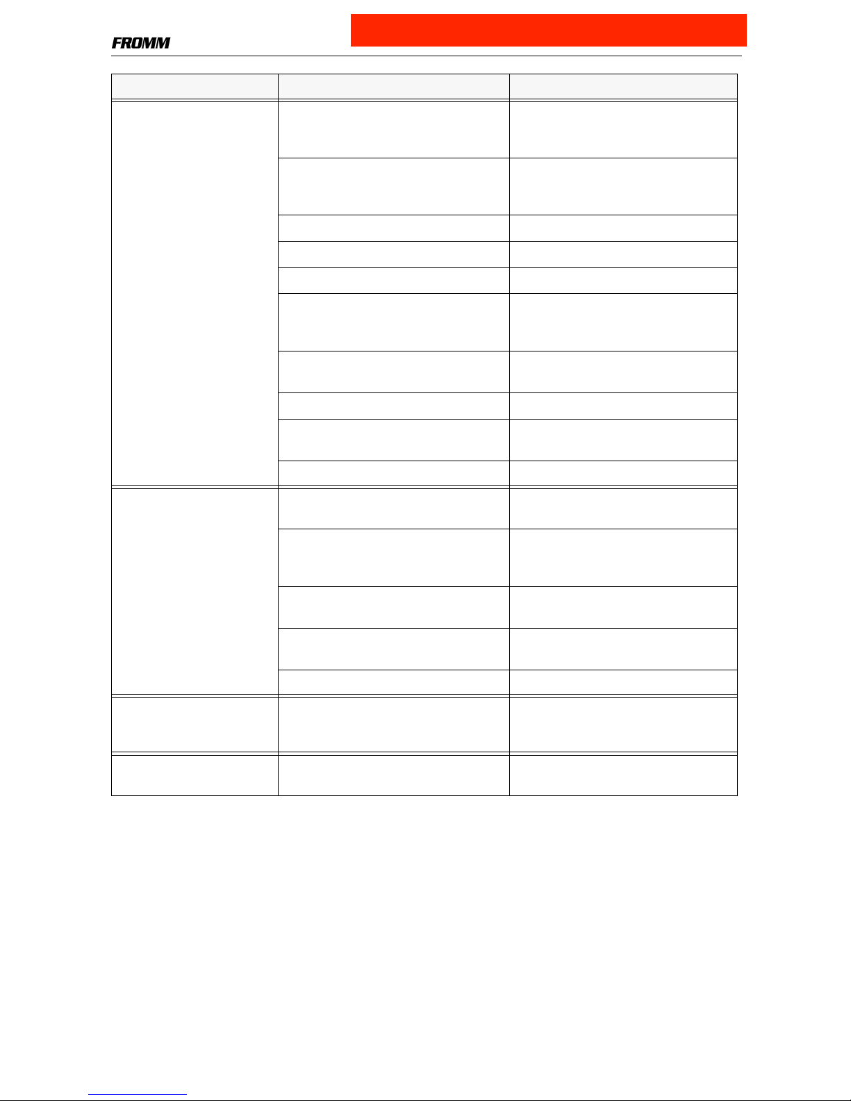
1.4.7 Assembly information
P32.8137
N1.1305
N1.6504
P32.8101
The bolt P32.8137 has to be glued into the
body P32.8101 using Loctite 603.
The screws N1.1305 have to be glued
with Loctite 222.
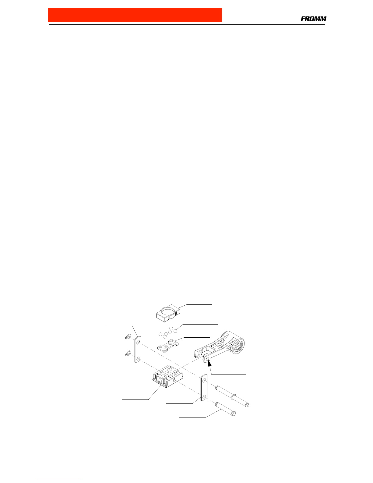
P32.8159
N2.2119
The parallel pin N2.2119 has to be
glued into the end cover P32.8159
with Loctite 603.
P32.8108
Grippers
One sided sealed bearings N3.1172 in the tensioning wheel.
The sealed side has to face to the outside. (see drawing)
When installing the grippers into the holder P32.8108
pay attention to the direction of the teeth (see drawing).
Purchase at Allstrap (866) 779-2673
1-14
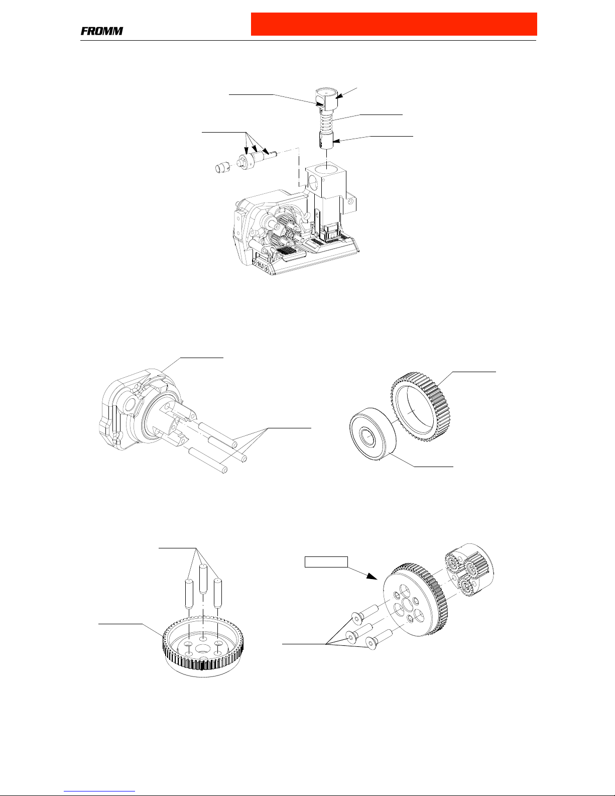
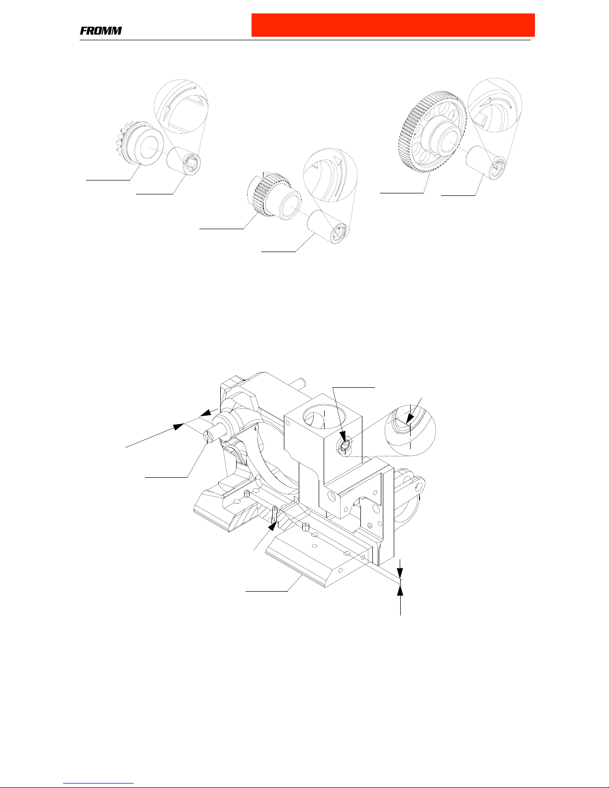
Pay attention to the mounting position of the needle free wheelings N3.4509 and N3.4520.
The rolling direction is stamped in at the front side of the free wheelings.
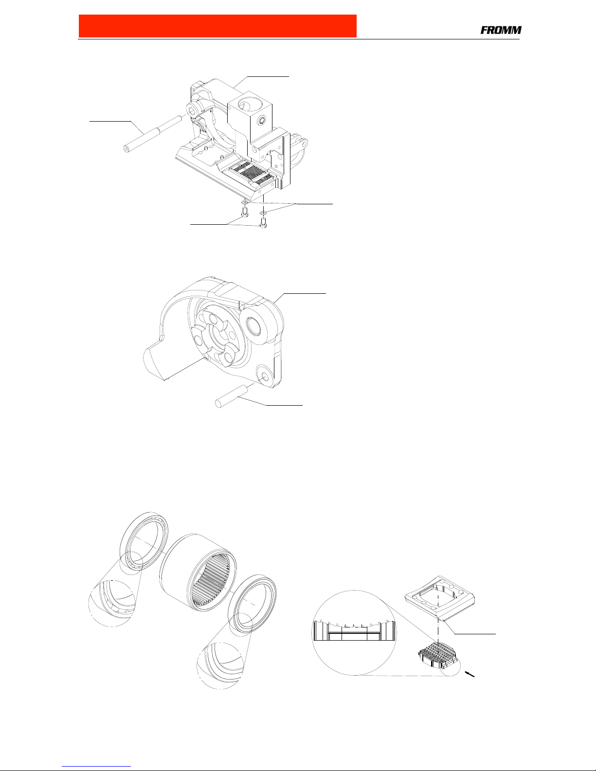
Position of the joint from slide bearings
Pay attention to the position of the joint from the slide bearing N31.3115 (see drawing).
N3.4509
P32.8134
P32.8138
N3.4509
N3.4520
P32.8139
1
2
,
5
5
+
-
0
,
2
N31.3115
press in pins flush
(4,4)
P32.8101
P32.8137
position joint
Purchase at Allstrap (866) 779-2673
 Loading...