

Fromm P325.0001.01 Service Manual
5-1
SERVICE MANUAL
BATTERY - POWERED
PLASTIC STRAPPING TOOL
MODEL P325.0001.01
Manual for authorized dealers and service points
P325.0001.01.sen/MAS/© 12.08

5-2
INDEX PAGE
5.1 ACCESSORIES 5-3
5.1.1 Battery . . . . . . . . . . . . . . . . . . . . . . . . . . . . . . . . . . . . . . . . . . . . . . . . . . . . . . . 5-3
5.1.2 Battery chargers . . . . . . . . . . . . . . . . . . . . . . . . . . . . . . . . . . . . . . . . . . . . . . . 5-3
5.1.3 Battery tester . . . . . . . . . . . . . . . . . . . . . . . . . . . . . . . . . . . . . . . . . . . . . . . . . . 5-3
5.1.4 Charger for car batteries . . . . . . . . . . . . . . . . . . . . . . . . . . . . . . . . . . . . . . . . . 5-3
5.1.5 Battery light . . . . . . . . . . . . . . . . . . . . . . . . . . . . . . . . . . . . . . . . . . . . . . . . . . . 5-3
5.2 TECHNICAL DETAILS 5-4
5.2.1 Electric schematic . . . . . . . . . . . . . . . . . . . . . . . . . . . . . . . . . . . . . . . . . . . . . . 5-4
5.2.2 Connecting plan. . . . . . . . . . . . . . . . . . . . . . . . . . . . . . . . . . . . . . . . . . . . . . . . 5-4
5.2.3 Strap tension . . . . . . . . . . . . . . . . . . . . . . . . . . . . . . . . . . . . . . . . . . . . . . . . . . 5-4
5.3 CONVERSION PARTS P325 5-5
5.4 PERIODIC MAINTENANCE AND CONTROL 5-6
5.4.1 Procedure . . . . . . . . . . . . . . . . . . . . . . . . . . . . . . . . . . . . . . . . . . . . . . . . . . . . 5-6
5.4.2 Troubleshooting. . . . . . . . . . . . . . . . . . . . . . . . . . . . . . . . . . . . . . . . . . . . . . . . 5-7
5.4.3 Battery test . . . . . . . . . . . . . . . . . . . . . . . . . . . . . . . . . . . . . . . . . . . . . . . . . . . 5-9
5.4.4 Checklist . . . . . . . . . . . . . . . . . . . . . . . . . . . . . . . . . . . . . . . . . . . . . . . . . . . . . 5-9
5.4.5 Glueing rules . . . . . . . . . . . . . . . . . . . . . . . . . . . . . . . . . . . . . . . . . . . . . . . . . . 5-9
5.4.6 Lubrication rules . . . . . . . . . . . . . . . . . . . . . . . . . . . . . . . . . . . . . . . . . . . . . . 5-10
5.4.7 Assembly informations . . . . . . . . . . . . . . . . . . . . . . . . . . . . . . . . . . . . . . . . . 5-10
5.4.8 Repair kit for electronic P32.2043 . . . . . . . . . . . . . . . . . . . . . . . . . . . . . . . . . 5-14
5.5 RECOMMENDED SPARE PARTS 5-15
5.6 ACCESSORY TOOLS 5-16
5.7 USE OF ACCESSORY TOOLS 5-17
5.8 ORDERING SPARE PARTS 5-21
5.8.1 Ordering manuals . . . . . . . . . . . . . . . . . . . . . . . . . . . . . . . . . . . . . . . . . . . . . 5-21
5.8.2 Ordering address. . . . . . . . . . . . . . . . . . . . . . . . . . . . . . . . . . . . . . . . . . . . . . 5-21
5.8.3 Finding out of the tool type (item number),
the serial number and the version number:. . . . . . . . . . . . . . . . . . . . . . . . . . 5-21
5.9 SERVICE ADDRESS 5-22
5.10 CHART OF TYPES 5-22
5-3
5.1 ACCESSORIES
5.1.1 Battery
Use only original Fromm batteries N5.4309 (NiCd) or N5.4316 (NiMH) for the P325 tool.
In case of a damaged battery housing, it can be ordered separately under item no. N5.4318.
5.1.2 Battery chargers
The battery charger must be ordered separately according to the table mentioned below.
Standard charger
Turbo charger
5.1.3 Battery tester
For testing the batteries order battery tester N7.5127.
5.1.4 Charger for car batteries
The charger N5.4407 must be ordered for connection to a car battery with 12 or 24V.
Can only charge NiCd-Batteries!
5.1.5 Battery light
For completely discharging of the battery the battery light N5.4313 can be used.
Item-No. Voltage / frequency Admitted for country
N5.4414 220 - 240V / 50 - 60Hz A, B, BG, BIH, BOL, BR, BY, CH, CL, CZ, D, DK, DZ, E, EAS, EST, ET, F,
FIN, GE, GR, H, HK, HR, I, IL, IND, IR, IRQ, IS, JOR, KSA, KWT, L, LAR, LT,
LV, MA, MC, MK, MOC, N, NL, P, PK, PE, PL, PRC, PY, RA, RCH, RI, RL,
RO, ROK, ROU, RP, RUS, S, SK, SLO, SYR, THA, TN, TR, UA, UAE, YU,
YV, (Z), (ZA), (ZW)
N5.4416 220 - 240V / 50 - 60Hz BRN, BRU, CY, EAK, EAT, GB, IRL, M, MAL, OM, SGP, Y
N5.4418 220 - 240V / 50 - 60Hz AUS, NZ
N5.4420 220V / 60Hz ROK
Item-No. Voltage / frequency Admitted for country
N5.4422 220 - 240V / 50 - 60Hz A, B, BG, BIH, BOL, BR, BY, CH, CL, CZ, D, DK, DZ, E, EAS, EST, ET, F,
FIN, GE, GR, H, HK, HR, I, IL, IND, IR, IRQ, IS, JOR, KSA, KWT, L, LAR, LT,
LV, MA, MC, MK, MOC, N, NL, P, PK, PE, PL, PRC, PY, RA, RCH, RI, RL,
RO, ROK, ROU, RP, RUS, S, SK, SLO, SYR, THA, TN, TR, UA, UAE, YU,
YV, (Z), (ZA), (ZW)
N5.4424 120V / 50-60Hz BR, C, CDN, CO, CR, DOM, EC, GCA, J, JA, KSA, LB, MEX, NIC, PA,
Puerto Rico, RC, RP, USA, YV
N5.4426 110V / 50 - 60Hz GB
N5.4428 220 - 240V / 50 - 60Hz BRN, BRU, CY, EAK, EAT, GB, IRL, M, MAL, OM, SGP, Y
N5.4430 220 - 240V / 50 - 60Hz AUS, NZ
5-4
5.2 TECHNICAL DETAILS
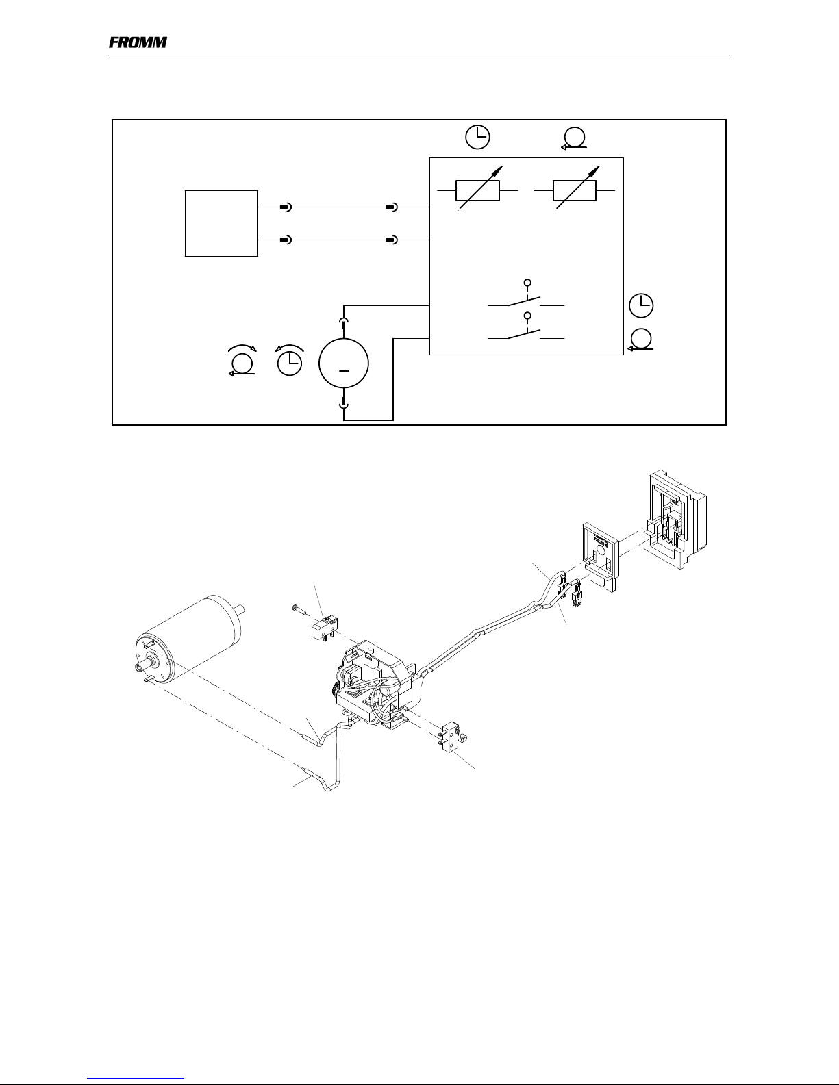
5.2.1 Electric schematic
5.2.2 Connecting plan
5.2.3 Strap tension
The tension force values mentioned in the P325 operation manual (600-3500N) are not achievable with each
strap. They depend on following factors:
• Hardness of the package,
the maximum tension force values are achievable with hard packages.
• Elongation and creep properties of the plastic strap,
the maximum tension force values are achievable by using plastic straps with a low elongation.
• Surface quality of the plastic strap,
the maximum tension force values are achievable with waxed and embossed straps.
• Strap width, strap thickness,
the maximum tension force values are achievable with thick and wide straps.
14,4VDC
+
M
+
-
black
red
red
white
N5.2359
N5.2322
black (-)
red (+)
red (+)
white (-)

5-5
5.3 CONVERSION PARTS P325
By converting to an other tool type the following parts must be changed:
The conversion from tools with the strap thickness 1.06-1.35 and 0.65-1.05 to tools
with the strap thickness 0.40-0.64 is possible. However the number of required parts
and labour cost are making a conversion not economic anymore.
43.0701
12.7 X
0.65-1.05
43.0711
13 X
0.65-1.05
43.0721
16 X
0.65-1.05
43.0722
16 X
1.06-1.35
43.0731
19 X
0.40-0.64
43.0732
19 X
0.65-1.05
43.0733
19 X
1.06-1.35
Spring bolt P32.1403 P32.1403 P32.1403 P32.1910
P32.1403 P32.1403 P32.1910
Tensioning body P35.0143 P35.0143 P35.0143 P35.0144
P35.0143 P35.0143 P35.0144
Gripper P32.1719 P32.1719 P32.1719 P35.3206
P32.1716 P32.1719 P35.3206
Gripper P32.1720 P32.1720 P32.1720 P35.3207
P32.1717 P32.1720 P35.3207
Gripper P32.1721 P32.1721 P32.1721 P35.3208
P32.1718 P32.1721 P35.3208
Holder P32.1229 P32.1229 P32.1229 P35.3209
P32.1229 P32.1229 P35.3209
Holder P32.1228 P32.1228 P32.1228 P35.3210
P32.1228 P32.1228 P35.3210
Strap guide P32.1242 P32.1243 P32.1246 P35.3212
P32.1724 P32.1724 P35.3213
Pressure spring N2.5237 N2.5237 N2.5237 N2.5282
N2.5237 N2.5237 N2.5282
Body P32.0160 P32.0160 P32.0160 P32.0160
P32.0164 P32.0160 P32.0160
Strap stop P32.1736 P32.1734 P32.1722 P32.1722
P32.1723 P32.1723 P32.1723
Tensioning wheel P35.3203 P35.3203 P35.3203 P35.3203
P35.3202 P35.3203 P35.3203
Guide pin P30.1156 P35.3226 P35.3216 P35.3216
P35.3218 P35.3218 P35.3218
Guide pin P30.1156 P35.3226 P35.3217 P35.3217
P35.3219 P35.3219 P35.3219
Cutter P32.1708 P35.3214 P35.3214 P35.3214
P35.3214 P35.3214 P35.3214
Guide case P32.1735 P35.3225 P35.3215 P35.3215
P35.3215 P35.3215 P35.3215
Seesaw lever P32.1248 P35.3220 P35.3220 P35.3220
P35.3220 P35.3220 P35.3220
Seesaw lever P32.1249 P35.3221 P35.3221 P35.3221
P35.3221 P35.3221 P35.3221
Thrust piece P32.1702 P35.3223 P35.3223 P35.3223
P35.3223 P35.3223 P35.3223
Attention!
When converting tools always change the item number on the type label
Replace following parts:
Type label N43.9143
2 x hammer head bolts N2.4902
Enclose the suitable operation manual with the tool after each
conversion
(see paragraph 5.8.1 Ordering manuals)
5-6
5.4 PERIODIC MAINTENANCE AND CONTROL
(Carry out 12- months cycles doing one shift work. Doing more shift work respectively more often.)
5.4.1 Procedure
Before using check tool for following possible faults:
• Visual test of the tool for loose, lost or damaged parts
• Clean all dirty parts of the tool, especially strap abrasion in the tensioning or the welding unit by
using compressed air. (Never use any hard tools like a wire brush or a screw driver for cleaning)
Carry out a test strapping and check following:
• Insertion of the strap
• Strap feed and strap tensioning
• Tensioning force adjustment (see operation manual P325)
• Cutting of the upper strap
• Welding time adjustment (see operation manual P325)
• Seal quality (see operation manual P325)
• Function of the LED - display
Proceed according to paragraph 5.4.2 after a fault appears.
Attention!
Remove battery from tool before each maintenance work.
For exchange of wearing parts see operation Manual P325.
Never use water or solvents for cleaning the tool’s surface.
5-7
5.4.2 Troubleshooting
Ensure before each tool repair that the battery is charged and
the tool’s specific strap is used
SYMPTOM CAUSE REMEDY
Tool doesn’t work at all Battery is empty or defective Charge or replace battery
Contact problems caused by a broken
battery housing N5.4318.
Replace battery housing
Contact problems caused by a
damaged cover P32.2010, insertation
part P32.2011 or damaged motor
housings P32.2040 and P32.2042
Replace cover insertation part or
motor housing
Contact problem of the internal wires Check contacts and fix them if
required, change defective parts or
solder on motor wires
Defective circuit board Replace circuit board
Tool doesn’t tension Tensioning wheel is dirty or worn Clean tensioning wheel or replace it,
don’t use any hard objects for this
(see operation manual P325)
P32.1051 is not meshing with
P32.2044, because spring N2.5822 is
defective or parts are dirty
Replace spring N2.5822,
clean dirty parts
Faulty tensioning wheel or tensioning
wheel is assembled reversed
Correct assembling
(see operation manual P325)
Grippers are dirty, worn or wrongly
assembled
Replace grippers, clean them or
assemble correct,
don’t use any hard objects for this
(see operation manual P325)
Gearing parts from the tensioning gear
are defective
Check tensioning gear and replace
defective parts
Defective motor P32.2065 Replace motor
Defective circuit board Replace circuit board
Micro switch N5.2359 for tensioning
is defective
Replace micro switch
Contact problem of the internal wires Check contacts and fix them if
required, change defective parts or
solder on motor wires
Defective gear bearings Replace bearings
Defective tensioning body Replace tensioning body
Needle free wheeling in gear wheel
P32.0156 or in conical gear wheel
P32.0151 assembled reversed
or defective
Assemble the needle free wheeling
correct or replace it
5-8
Tensioning wheel turns
back immediately after the
tensioning cycle
Defective needle free wheeling
N3.4509 in P32.0156
Check parts and replace if necessary
Tool doesn’t weld Welding gripper P32.1511 is dirty or
worn
Replace or clean welding gripper, don’t
use any hard objects for this
(see operation manual P325)
Welding stop gripper is dirty or worn Replace or clean welding stop gripper,
don’t use any hard objects for this
(see operation manual P325)
Damaged housing parts Replace housing parts
Defective circuit board Replace circuit board
Defective motor P32.2065 Replace motor
Pressure spring N2.5294 defective Replace pressure spring
Needle free wheeling N3.4509 in
P32.0150 defective or assembled
reversed
Assemble the needle free wheeling
correct or replace it
Gearing parts of the welding gear are
defective
Check welding gear and replace
defective parts
Micro switch N5.2322 for welding
is defective
Replace micro switch
Contact problem of the internal wires Check contacts and fix them if
required, change defective parts or
solder on motor wires
Defective gear bearing Replace bearing
Tool badly cuts the strap or
doesn’t cut at all
Cutter is worn or damaged Replace cutter
(see operation manual P325)
Wrong adjustment of the coupler Check adjustment and readjust if
necessary
(see operation manual P325)
Welding gripper is worn Replace welding gripper
(see operation manual P325)
Welding time too short Change adjustment
(see operation manual P325)
Defective pressure spring
N2.5237/N2.5282
Replace pressure spring
Tool switches off after a few
strappings
(Displaying empty battery)
Battery defective or empty Check the battery and change
defective batteries
Gear noise Tensioning or welding gear is worn Check component parts and replace
defective ones
SYMPTOM CAUSE REMEDY
5-9
5.4.3 Battery test
The battery should be checked while each maintenance by using the battery tester N7.5127.
The use is described in the instruction manual of the battery tester.
• NiCd-Batteries 14,4V / (2,4Ah) must be replaced at a capacity less than 70% (1,7 Ah).
• NiMH-Batteries 14,4V / (3Ah) must be replaced at a capacity less than 70% (2,1Ah).
5.4.4 Checklist
Carry out some test strappings and check following tool components.
• Inserting of the strap
• Insert battery in the tool and check function of the LED-display (see operation manual P325)
• Strap feed and strap tension
• Tension force adjustment (see operation manual P325)
• Cutting of the upper strap
• Welding time adjustment (see operation manual P325)
• Seal quality (see operation manual P325)
• Function of the LED-display (see operation manual P325)
• Correct type label
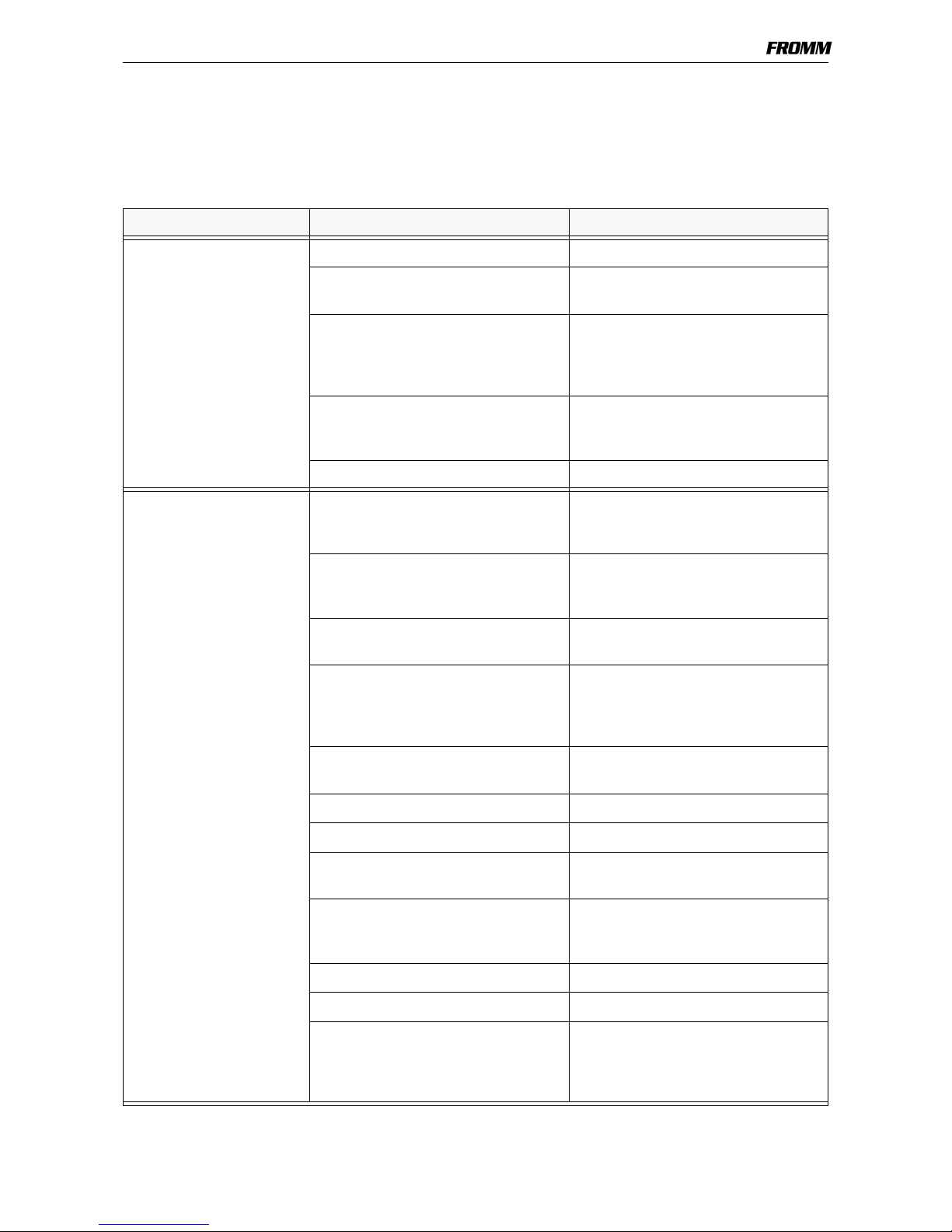
5.4.5 Glueing rules
Following parts have to be glued with LOCTITE 603:
Planet shaft P35.3103
with the parallel pins N2.2145.
Tensioning body P35.3204/05
with the parallel pins N2.2189
Body P32.2003/45 with
swivel shaft P32.2037
and parallel pins N21.2101
N2.2145
P35.3103
N2.2189
P35.3204/05
N21.2101
P32.2037
P32.2003/45
5-10
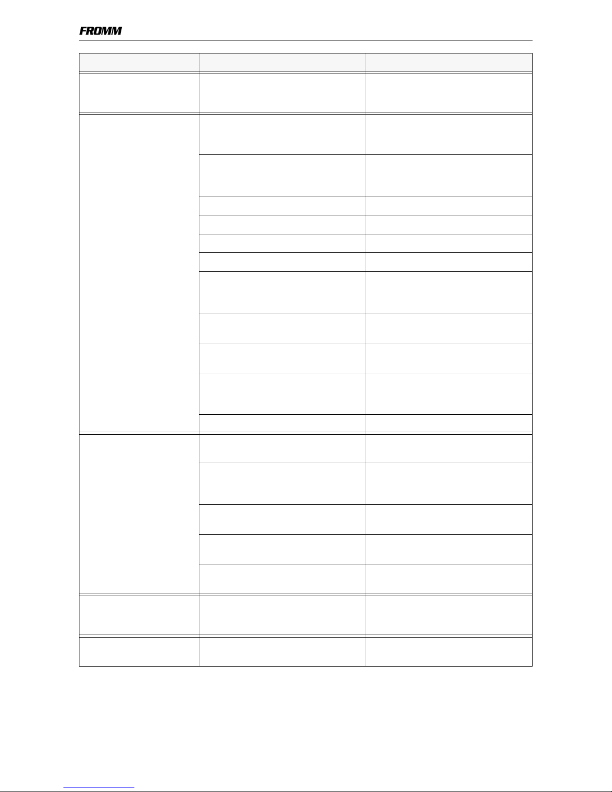
Additional the screws N1.2112 have to be glued with the
idler step P35.0130 using LOCTITE 222.
Don’t clamp the planet shaft on the pinion while loosening or
tightening the screws N1.2112.
5.4.6 Lubrication rules
All gear parts have to be lubricated with MOLYKOTE BR 2 PLUS grease.
Lubrication interval: While each maintenance or after 12 months at the latest.
All bearing parts of the welding unit have to be cleaned and
lubricated with Klüber Isoflex Alltime SL2 grease while
each maintenance.
Lubrication interval: While each maintenance or after 12
months at the latest.
All other parts have to be greased due to the explosion drawing.
Lubrication interval: While each maintenance
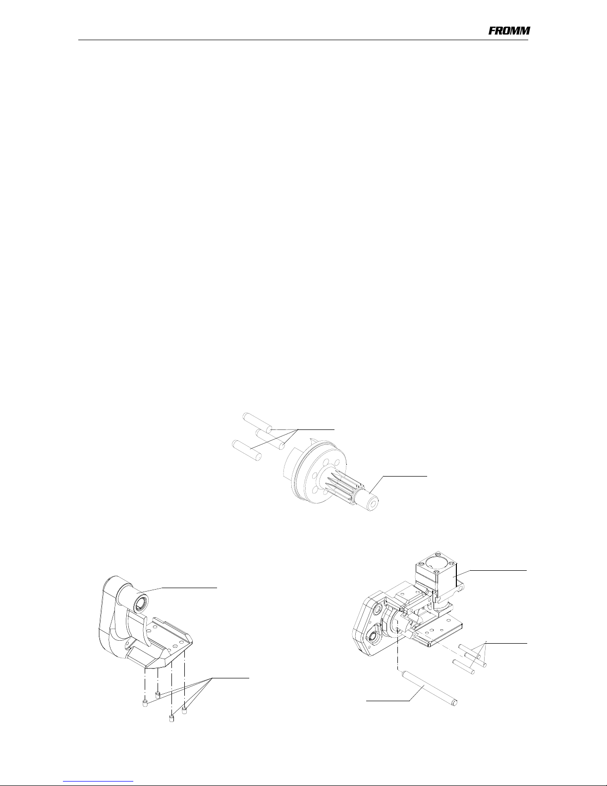
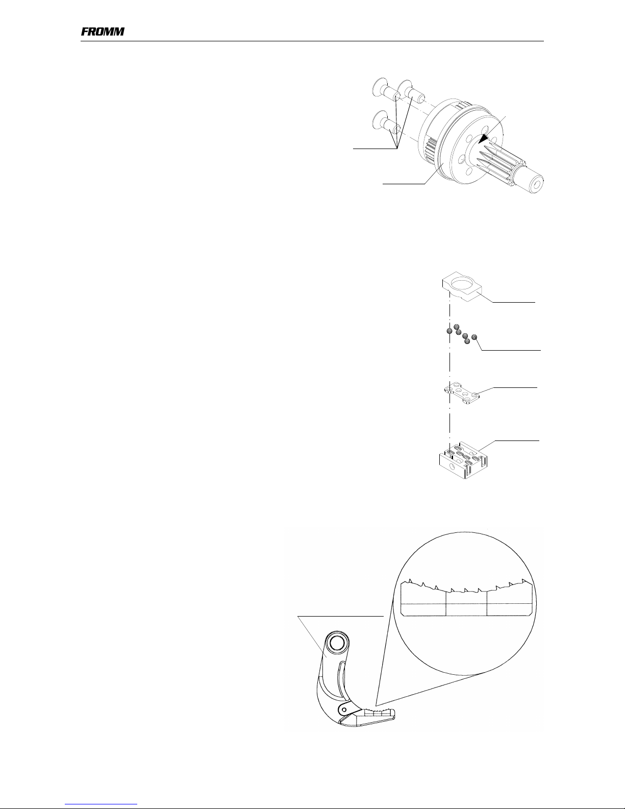
5.4.7 Assembly informations
Pay attention to the direction of the teeths
while assembling the grippers into the
tensioning body P35.3204/P35.3205.
(look at the picture)
P35.0130
N1.2112
Clamp
here
P32.1029
N3.1702 (6X)
P32.1027
P32.1511
Bearing
welding unit
P35.3204/P35.3205
Grippers
5-11
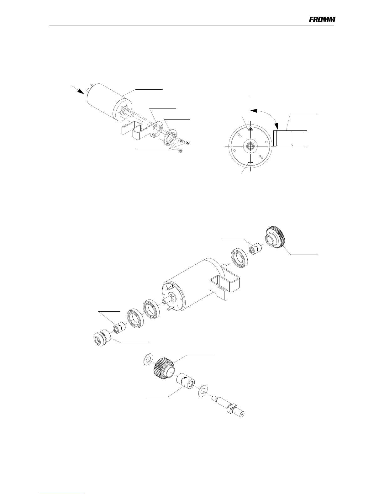
Like imaged the connections of the motor P32.2065 must be adjusted 90° to the sheet P32.2064.
The mounting of the sheet happens by fixation of the disk P32.2063 with the screws N1.2216.
To adjust the sheet the motor could be placed into the housing.
Pay attention to the mounting position of the needle free wheelings N3.4509 and N3.4520.
The rolling direction is stamped in at the front side of the free wheelings.
P32.2065
P32.2064
P32.2063
N1.2216
90°
P32.2064
(+)
(-)
X
view X
N3.4509
P32.2036
P32.2018
N3.4520
N3.4509
P32.2015
5-12
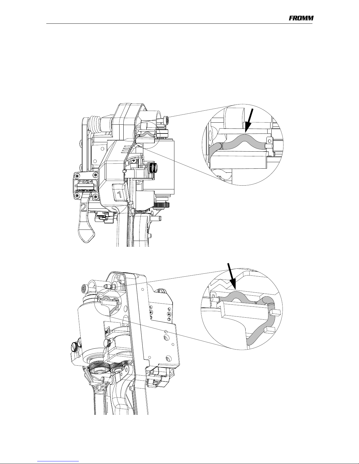
Pay attention to the mounting position of the eccentric (P32.2034).
Adjustment of the lever P32.1414
If the handle lever after welding and cooling of the strap can be pulled up difficult or not at all, the adjustment
of the lever P32.1414 must be checked.
It can be done as follows:
- Loose lock nut N1.5120
- Screw in the socket set screw N1.3150, until it touches the coupler P32.1410
- Tighten lock nut N1.5120
Test without battery and strap:
- Press welding lever down until it locks
- Pull handle lever up
The welding lever must move up before the tension body swings forward.
Swings the tension body forward first, the strap blocks the welding jaw and the handle lever can be pulled up
difficult or not at all.
Afterwards do a test strapping and readjust if necessary.
(P325) Eccentric down
Welding lever
Tension body
P32.1410
N1.3150
N1.5120
P32.1414
Handle lever
5-13
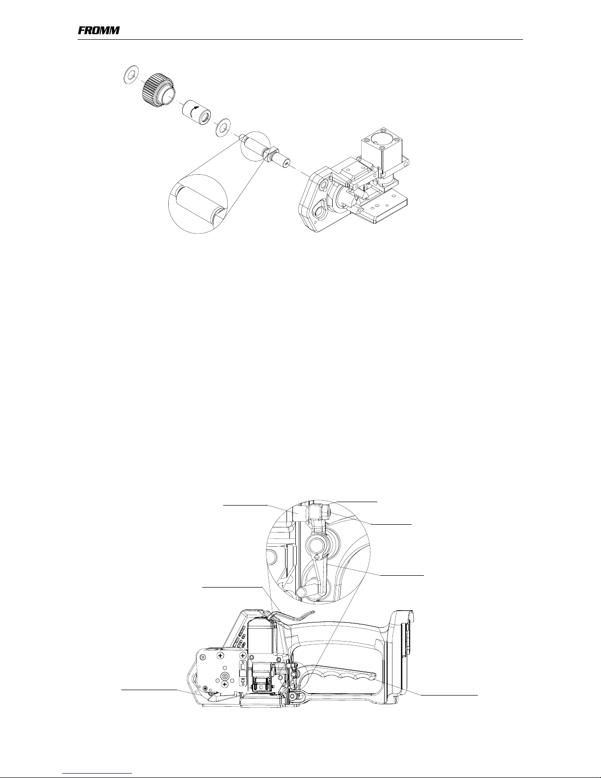
Connection of the electronic to the motor
In order to prevent a cracking of the terminals on the motor, the connection cables of the electronic are laid
with a light bend before soldered to the motor.
This method is used for all battery powered plastic strapping tools.

5-14
5.4.8 Repair kit for electronic P32.2043
The repair kit can be ordered with the article number P32.2075.
With the repair kit defective plugs on the connection cables of the electronic can be changed.
Procedure:
• Cut the cables to a length of 126 mm (see drawing).
• Strip wire ends 6mm,
• tin plate wire ends,
• push insulating hose N5.3420 above the cables.
• Overlap the cables and solder them together,
• push the insulating hoses over the solder joint X.
The cable length after soldering must be between 240 and 248mm (see drawing).
red
white
black
red
6
1
2
6
2
4
0
+
8
P32.2043
N5.3420
P32.2071
P32.2073
X
X
5-15
5.5 RECOMMENDED SPARE PARTS
Following spare parts are recommended for stock keeping:
Besides schould be stocked the wearing parts of the different Types.
Stock only parts from tools that are in sale.
Item-No. Description Pieces per tool
N1.1305 Screw 2
N1.1904 Screw 4
N1.1909 Flat head screw 2
N1.1925 Screw 1
N1.1927 Flat head screw 1
N1.1929 Screw 1
N1.1934 Flat head screw 4
N1.6503 Safety washer 5
N1.6504 Safety washer 13
N1.6505 Safety washer 3
N1.7206 PT-screw 1
N1.7211 PT-screw 7
N2.1118 Security ring 1
N2.1121 Security ring 5
N2.1606 Spring ring 1
N2.1805 Tensioning ring 1
N3.1702 Ball 6
N3.4509 Free wheeling 2
N3.4520 Free wheeling 1
N5.2322 Micro switch 1
N5.2359 Micro switch 1
N5.4318 Housing 1
P32.0160/64 Body 1
P32.2010 Cover 1
P32.2011 Insertation part 1
P32.2028 Lever 1
P32.2040 Motor housing 1
P32.2042 Motor housing 1
P32.2043 Circuit board 1
P32.2065 Electric motor 1
P35.3211 End cover 1

5-16
5.6 ACCESSORY TOOLS
* a) These tools are also included in the P320 tool set.
b) These tools are also included in the P321 tool set.
c) These tools are also included in the P322 tool set.
d) These tools are also included in the P323 tool set.
e) These tools are also included in the P355 tool set.
f) These tools are also included in the P356 tool set.
g) These tools are also included in the P324 tool set.
Item
number
Description Application
N71.3235 *a,b,c,d,e,f,g Press in and press out arbor N3.4509/P32.2036;
N3.4509/P32.2015
N71.3237 *a,b,c,d,e,f,g Press in and press out arbor N3.1159/P32.2016;
N3.2356/P35.3211
N71.3239 *a,b,c,d,e,f,g Press in arbor N3.2347/P32.1510
N71.3240 *a,b,c,d,e,f,g Press out arbor N3.2347/P32.1510
N71.3241 *a,b,c,d,e,f,g Press in and press out pressure pad N3.2347/P32.1510
N71.3243 *a,b,c,d,e,f,g Press in arbor N3.1134, P32.1023/P32.1022
N71.3244 *a,b,c,d,e,f,g Press out arbor N3.1134, P32.1023/P32.1022
N71.3245 *a,b,c,d,e,f,g Pressure pad N3.1134, P32.1023/P32.1022;
N3.2356/P35.3211
N71.3247 *a,d,e,f,g Press in and press out pressure pad N3.1157/P35.3103
N71.3248 *a,b,c,d,e,f,g Press in arbor N3.3150/P35.3204/05
N71.3250 *a,c,e,f,g Press in and press out arbor N3.3172/P32.2003/45
N71.3264 *b,d,f Press in and press out arbor N3.1157/P35.3103
N71.3266 *b,d,f Press out arbor N3.2356/P35.3211
N71.3267 *b,d,f Press out arbor N3.3150/P35.3204/05
N71.3268 *b,d,f Press out pressure pad N3.3150/P35.3204/05
N71.3282 g Press in and press out pressure pad N3.4509/P32.2015; N3.4520/
P32.2018; N3.4509/P32.2036
N71.3283 g Press in and press out pressure pad N3.1159/P32.2016
N71.3284 g Press out arbor N3.4520/P32.2018
N71.3285 g Press out pressure pad N3.1137/P32.2015
N71.3286 g Press out arbor N3.1137/P32.2015
 Loading...