

Fromm P320 Operation Manual & Spare Parts List
43032402.en/DS/© 04.99
OPERATION MANUAL / SPARE PARTS LIST
BATTERY - POWERED
PLASTIC STRAPPING TOOL
MODEL P320
43.0324.02
2
INDEX PAGE
1 SAFETY INSTRUCTIONS 3
2 TECHNICAL DATA 4
3 ACCESSORIES 5
3.1 Battery. . . . . . . . . . . . . . . . . . . . . . . . . . . . . . . . . . . . . . . . . . . . . . . . . . . . . . . . 5
3.2 Battery - chargers . . . . . . . . . . . . . . . . . . . . . . . . . . . . . . . . . . . . . . . . . . . . . . . 5
3.3 Wearing plate . . . . . . . . . . . . . . . . . . . . . . . . . . . . . . . . . . . . . . . . . . . . . . . . . . 5
3.4 Suspension . . . . . . . . . . . . . . . . . . . . . . . . . . . . . . . . . . . . . . . . . . . . . . . . . . . . 5
4 OPERATING ELEMENTS 6
5 OPERATION 6
5.1 Installation. . . . . . . . . . . . . . . . . . . . . . . . . . . . . . . . . . . . . . . . . . . . . . . . . . . . . 6
5.2 Adjustments. . . . . . . . . . . . . . . . . . . . . . . . . . . . . . . . . . . . . . . . . . . . . . . . . . . . 7
5.2.1 Preselecting of the strap tension. . . . . . . . . . . . . . . . . . . . . . . . . . . . . . . . . . . . 7
5.2.2 Adjusting the welding time. . . . . . . . . . . . . . . . . . . . . . . . . . . . . . . . . . . . . . . . . 7
5.2.3 Adjusting the welding pressure . . . . . . . . . . . . . . . . . . . . . . . . . . . . . . . . . . . . . 7
5.3 Feeding the strap around the package . . . . . . . . . . . . . . . . . . . . . . . . . . . . . . . 8
5.4 Inserting the strap . . . . . . . . . . . . . . . . . . . . . . . . . . . . . . . . . . . . . . . . . . . . . . . 8
5.5 Tensioning the strap . . . . . . . . . . . . . . . . . . . . . . . . . . . . . . . . . . . . . . . . . . . . . 8
5.6 Sealing the straps . . . . . . . . . . . . . . . . . . . . . . . . . . . . . . . . . . . . . . . . . . . . . . . 9
5.7 Removing the tool . . . . . . . . . . . . . . . . . . . . . . . . . . . . . . . . . . . . . . . . . . . . . . . 9
5.8 Seal - Control . . . . . . . . . . . . . . . . . . . . . . . . . . . . . . . . . . . . . . . . . . . . . . . . . . 9
6 SPARE PARTS LIST 43.0324.02 12
7 CHART OF TYPES 16
8 WARRANTY CONDITIONS AND LIABILITY 16
9 APPROPRIATE USE 16
10 EXCHANGE OF WEARING PARTS 17
10.1 Exchange of tensioning wheel and grippers . . . . . . . . . . . . . . . . . . . . . . . . . . 17
10.2 Exchange of cutter, welding stop gripper and welding gripper . . . . . . . . . . . . 18
10.3 Adjustment of the coupler P32.1250. . . . . . . . . . . . . . . . . . . . . . . . . . . . . . . . 19
11 ELECTRIC SCHEMATIC 20
12 SERVICE 20
13 CLEANING 20
3
1 SAFETY INSTRUCTIONS
Read these instructions carefully. Failure to follow these instructions can result in severe personal injury.
Operation with battery
Environment protection:
• Do not dispose of used batteries in the household refuse,
water or by burning them.
FROMM distributors offer an environment friendly battery
disposal service.
Danger of shortcircuit:
• Do not store batteries together with metal objects.
• Do not open batteries and store them only in dry and frostproof rooms. The maximum ambient temperature is 50˚C.
Keep dry at all times.
• Never charge a damaged battery. Replace by a new one
immediately.
Eye injury hazard
Failure to wear safety glasses with side shields can result in
severe eye injury or blindness. Always wear safety glasses with
side shields which conform to ANSI Standard Z87.1.
Operation
Tool must not be used by persons not properly trained in their use.
Before tensioning strap, read and understand the tool operating
instructions. Failure to follo w the oper ating instructions or improper
load positioning could result in strap breakage.
Become familiar with your tool and keep fingers away from areas
that can pinch or cut.
Joints
You are fully responsible to review the joints made by your tool.
Become familiar with the seal control and seal adjustment
described in this operation manual. Misformed joints may not
secure the load and could cause serious injury. Never handle or
ship any load with improperly formed joints.
Dispensing strap
Only dispense strap from a dispenser specifically designed for
strap.
Tuck strap end back into dispenser when not in use.
Strap warnings
Never use strap as a means of pulling or lifting loads. Failure to
follow these warnings can result in severe personal injury.
Strap breakage hazard
Improper operation of the tool, excessive tensioning, using strap
not recommended for this tool or sharp corners on the load can
result in a sudden loss of strap tension or in strap breakage during
tensioning, which could result in the following:
• A sudden loss of balance causing you to fall.
• Both tool and strap flying violently towards your face.
Note as follows:
• If the load corners are sharp, use edge protectors.
• Place the strap correctly around a properly positioned
load.
• Positioning yourself in-line with the strap, during
tensioning and sealing, can result in severe personal
injury from flying strap or tool. When tensioning or sealing,
position yourself to one side of the strap and keep all
bystanders away.
• Use the correct strap quality, strap width, strap gauge and
strap tensile strength recommended in this manual for
your tool. Using strap not recommended for this tool can
result in strap breakage during tensioning.
Cutting tensioned strap
When cutting strapping, use the proper strapping cutter and keep
other personnel and yourself at a safe distance from the strap.
Always stand to side of the strap, away from the direction the
loosened strap end will fly. Use only cutters designed for strap and
never hammers, pliers, hacksaws, axes, etc.
Fall hazard
Keep your working area tidy. Untidiness of your working area may
cause a risk of injury. Maintaining improper footing and/or balance
when operating the tool can cause you to fall. Before tensioning
and especially in elevated areas, always establish good balance.
Both feet should be securely placed on a flat, solid surface,
especially when working in elevated areas. Do not use the tool
when you are in an awkward position.
Pay attention to the rules and regulations for preventions of
accident which are valid for the work place.
Tool hazards
A well maintained tool is a safe tool!
Check tool regularly for broken or worn parts. Do not operate a
tool with broken or worn parts.
Never modify any tool. Modification can result in severe bodily
injury.

4
2 TECHNICAL DATA
Description of the tool
The tool model P320 has been designed to strap packages with plastic strapping. The plastic strapping is fed
around the package manually or in combination with a strap feeder. The straps are inserted in the tool,
automatically tensioned, sealed by friction welding and separated.
Tool size with battery
Length: 335 mm / 13.2"
Width: 165 mm / 6.5"
Height: 125 mm / 4.9"
Weight: 4.2 kg / 9.3 lbs
Sound information
The A-weighted equivalent continuous sound level at the work place of the machine operator is
typical 76 dB (A).
This value has been determined according to DIN 45 635 T3 (11.85).
Vibration information
The weighted root mean square value of acceleration is typical below 2,5m/s2.
This value has been determined according to DIN EN 28 662 T1 (01.93).
Strap material
Strap qualities: PET (Polyester) and PP (Polypropylen) plain or embossed.
Use only plastic straps recommended by your sales shop (name and address
on the rear of the operation manual).
Strap dimensions: 10.0 - 16.0 mm / 3/8 - 5/8“ x 0.4 - 1.05 mm / .016 - .041“ (see chart of types).
Use only plastic straps with the correct strap dimensions for your tool.
Strap tension
Tensioning force: Adjustable from 400 - max. 2000 N / 90 - max. 450 lbs.
The maximum value depends on the strap quality.
Tensioning speed: approx. 270 mm/s / 10.6"/sec.
Seal efficiency: approx. 75% of the tensile strength of the plastic strap (depending on the strap
quality).
Battery
Voltage / capacity: 12 VDC / 2.0 Ah
Strappings per charge: approx. 250 strappings with PP strap
approx. 120 strappings with PET strap
(depending on the strap quality, strap dimensions, ambient temperature, tensioning
distance etc.)
Life cycle: approx. 3000 charges
Charging time:
Working temperature: The ambient temperature should be between 5˚ and 45˚ C (41˚ and 113˚F).
The best performance is achieved between 15˚ and 20˚C (59˚ and 68˚F).
Battery - charger: N5.4401 N5.4402 N5.4403 N5.4404 N5.4405
Charging time: approx.
20 min
approx.
20 min
approx.
80 min
approx.
20 min
approx.
36 min
5
3 ACCESSORIES
Use only parts and accessories mentioned in the operating instruction. Using other
parts or accessories can cause injuries to you and other persons.
3.1 Battery
One battery is included in the P320 delivery.
Battery for replacement or exchange can be
ordered under item number N5.4303.
3.2 Battery - chargers
The battery charger must be separately ordered according to the table mentioned below.
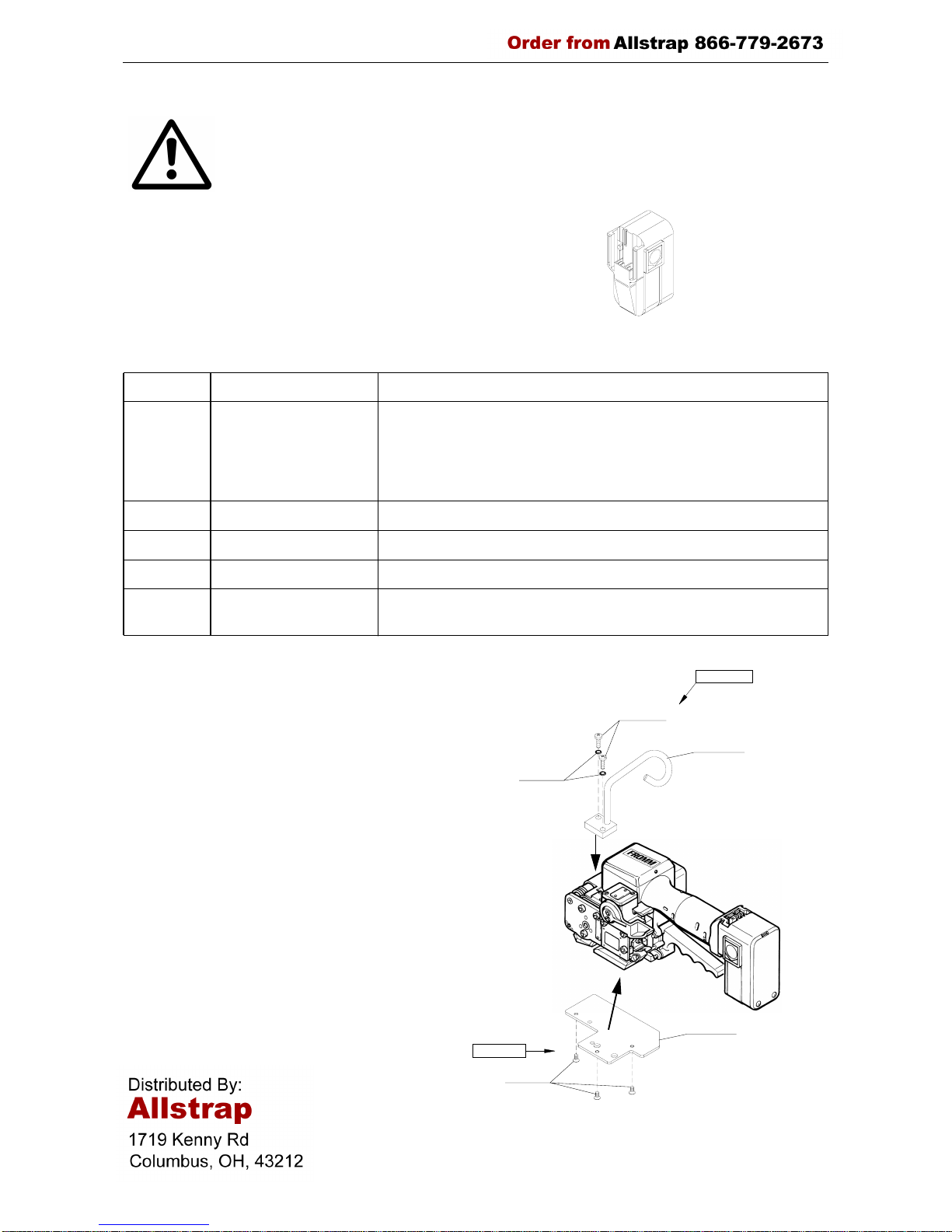
3.3 Wearing plate
As an option, tool can be equipped with a wearing
plate to protect base from excessive wear on
abrasive package surfaces (like bricks, concrete
blocks etc.).
The complete wearing plate can be ordered
together with the fastening screws under item
number P32.0111.
3.4 Suspension
When working stationary in normal position, the
P320 can be suspended at its suspension bracket
at a spring loaded balancer.
The complete suspension with the fastening
screws and washers can be ordered under item
number P32.0112.
Item-No. Voltage / frequency Admitted for country
N5.4401 220 - 240V / 50 - 60Hz A, B, BG, BIH, BOL, BR, CH, CL, CZ, D, DK, DZ, E, EAS, EST, ET,
EY, F, FIN, GE, GR, H, HK, HR, I, IL, IND, IR, IRQ, IS, JOR, KSA,
KWT, L, LAR, LT, LV, MA, MC, MK, MOC, N, NL, P, PK, PE, PL,
PRC, PY, RA, RCH, RI, RL, RO, ROK, ROU , RP, RUS , S , SK, SLO,
SYR, THA, TN, TR, UA, UAE, YU, YV, (Z), (ZA), (ZW)
N5.4402 240V / 50 - 60Hz BRN, BRU, CY, EAK, EAT, GB, IRL, M, MAL, OM, SGP, Y
N5.4403 110V / 50Hz GB
N5.4404 230 - 240V / 50 - 60Hz AUS, NZ
N5.4405 110 - 127V / 50 - 60Hz BR, C, CDN, CO, CR, DOM, EC, GCA, J, JA, KSA, LB, MEX, NIC,
PA, Puerto Rico, RC, RP, USA, YV
N5.4303
P32.0112
N1.1912
N1.6503
P32.1303
P32.0111
P32.1301
N1.2221
6
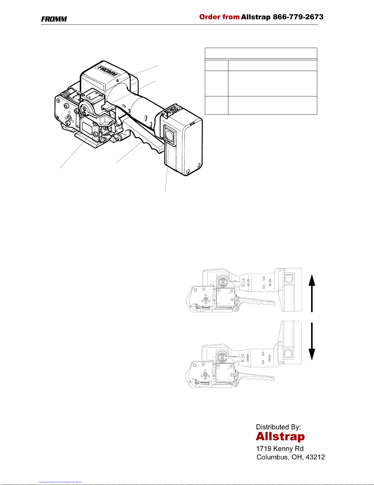
4 OPERATING ELEMENTS
5 OPERATION
5.1 Installation
Do not expose the tool to rain!
For safety reasons the battery is delivered uncharged.
Charge the battery before working. See separate operating instruction of the battery charger.
Inserting the battery
Insert the batter y from bottom to top into the tool both
unlatching push buttons latch.
Depending on the application, the battery can also be
inserted from top to bottom in order achieve a better
handling.
Removing the empty battery
If the red LED starts lighting while a tensioning or
welding procedure, the capacity of the battery is
exhausted. All electric functions of the tool are block ed.
The seal efficiency is insufficient.
Warning! Straps with insufficient seal strength must be removed from the package!
The battery must be recharged.
Push the unlatching push buttons at both sides of the battery.
Push the battery out of the tool in the opposite direction of insertion.
Switch rocker
Lever
Unlatching push button
LED
Handle lever
LED
Red Charge the battery.
Yellow Cooling time is running, the
lever must be held in welding
position.
Green Cooling time elapsed, turn the
lever in start position.
 Loading...