

Fromm A3H.0003 Operation Manual And Spare Parts List
OPERATION MANUAL / SPARE PARTS LIST
For Parts & Service 1-877-862-6699
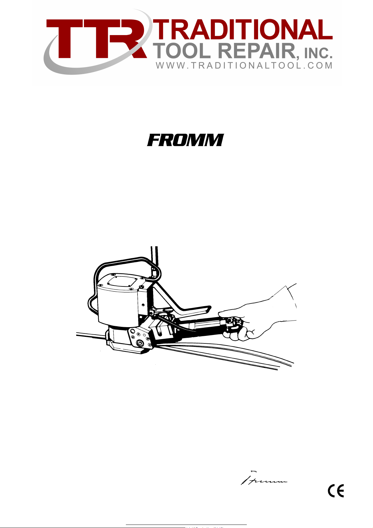
PNEUMATIC
STEEL STRAPPING TOOL
MODEL A3H.0003
13.6090.02
13609002.en/MAS/© 03.06
CE Declaration of conformity
We declare that the machine A3H
is in conformity with the following standard or
standardised documents:
98/37/EEC
FROMM Holding AG
Hinterbergstrasse 26
CH - 6330 Cham
28.02 2005
R.Fromm
Director

INDEX PAGE
For Parts & Service 1-877-862-6699
1 SAFETY INSTRUCTIONS 3
2 WARRANTY CONDITIONS AND LIABILITY 4
3APPROPRIATE USE 4
4 TECHNICAL DATA 4
4.1 Dimensions . . . . . . . . . . . . . . . . . . . . . . . . . . . . . . . . . . . . . . . . . . . . . . . . 4
4.2 Compressed air . . . . . . . . . . . . . . . . . . . . . . . . . . . . . . . . . . . . . . . . . . . . . 5
4.3 Steel strapping . . . . . . . . . . . . . . . . . . . . . . . . . . . . . . . . . . . . . . . . . . . . . 5
4.4 Sound information . . . . . . . . . . . . . . . . . . . . . . . . . . . . . . . . . . . . . . . . . . . 5
4.5 Vibration information . . . . . . . . . . . . . . . . . . . . . . . . . . . . . . . . . . . . . . . . . 5
5 INSTALLATION 5
5.1 Compressed air connection. . . . . . . . . . . . . . . . . . . . . . . . . . . . . . . . . . . . 5
5.2 Suspension of tool. . . . . . . . . . . . . . . . . . . . . . . . . . . . . . . . . . . . . . . . . . . 5
6 CHART OF TYPES 6
6.1 A3H.0003 . . . . . . . . . . . . . . . . . . . . . . . . . . . . . . . . . . . . . . . . . . . . . . . . . 6
6.2 A3H.0003/D (with a throttle valve). . . . . . . . . . . . . . . . . . . . . . . . . . . . . . . 6
7 OPERATION 7
7.1 Feeding the strap around the package . . . . . . . . . . . . . . . . . . . . . . . . . . . 7
7.2 Loading the strap. . . . . . . . . . . . . . . . . . . . . . . . . . . . . . . . . . . . . . . . . . . . 7
7.3 Tensioning the strap . . . . . . . . . . . . . . . . . . . . . . . . . . . . . . . . . . . . . . . . . 7
7.4 Sealing the strap . . . . . . . . . . . . . . . . . . . . . . . . . . . . . . . . . . . . . . . . . . . . 8
7.5 Removing the tool from the tensioned and sealed strap. . . . . . . . . . . . . . 8
8 SEAL CONTROL 9
8.1 Correct seal . . . . . . . . . . . . . . . . . . . . . . . . . . . . . . . . . . . . . . . . . . . . . . . . 9
8.2 Incorrect seal (the sealing mechanism is adjusted too high). . . . . . . . . . . 9
8.3 Incorrect seal (the sealing mechanism is adjusted too low) . . . . . . . . . . . 9
9 SPARE PARTS LIST 13.6090.02 12
10 SEAL ADJUSTMENT 16
11 MAINTENANCE 16
11.1 Air-unit . . . . . . . . . . . . . . . . . . . . . . . . . . . . . . . . . . . . . . . . . . . . . . . . . . . 16
11.2 Cleaning . . . . . . . . . . . . . . . . . . . . . . . . . . . . . . . . . . . . . . . . . . . . . . . . . 16
11.3 Lubrication. . . . . . . . . . . . . . . . . . . . . . . . . . . . . . . . . . . . . . . . . . . . . . . . 16
11.4 Control of oil level . . . . . . . . . . . . . . . . . . . . . . . . . . . . . . . . . . . . . . . . . . 17
12 EXCHANGE OF WEARING PARTS 17
12.1 Shear blade . . . . . . . . . . . . . . . . . . . . . . . . . . . . . . . . . . . . . . . . . . . . . . . 17
12.2 Tensioning wheel. . . . . . . . . . . . . . . . . . . . . . . . . . . . . . . . . . . . . . . . . . . 18
12.3 Square gripper. . . . . . . . . . . . . . . . . . . . . . . . . . . . . . . . . . . . . . . . . . . . . 18
12.4 Punch and die . . . . . . . . . . . . . . . . . . . . . . . . . . . . . . . . . . . . . . . . . . . . . 19
WWW.TRADITIONALTOOL.COM
2

1 SAFETY INSTRUCTIONS
For Parts & Service 1-877-862-6699
Read these instructions carefully. Failure to follow these instructions can result in severe personal injury.
Eye injury hazard
Failure to wear safety glasses with side shields can result in
severe eye injury or blindness. Always wear safety glasses with
side shields which conform to ANSI Standard Z87.1.
Operation
Tool must not be used by persons not properly trained in their use.
Before tensioning strap, read and understand the tool operating
instructions. Failure to follow the operating instructions or improper
load positioning could result in strap breakage.
Become familiar with your tool and keep fingers away from areas
that can pinch or cut.
Joints
You are fully responsible to review the joints made by your tool.
Become familiar with the seal control and seal adjustment described in this operation manual. Misformed joints may not secure the
load and could cause serious injury. Never handle or ship any load
with improperly formed joints.
Strap breakage hazard
Improper operation of the tool, excessive tensioning, using strap
not recommended for this tool or sharp corners on the load can
result in a sudden loss of strap tension or in strap breakage during
tensioning, which could result in the following:
• A sudden loss of balance causing you to fall.
• Both tool and strap flying violently towards your face.
Note as follows:
• If the load corners are sharp, use edge protectors.
• Place the strap correctly around a properly positioned
load.
• Positioning yourself in-line with the strap, during tensioning and sealing, can result in severe personal injury from
flying strap or tool. When tensioning or sealing, position
yourself to one side of the strap and keep all bystanders
away.
• Use the correct strap quality, strap width, strap gauge and
strap tensile strength recommended in this manual for
your tool. Using strap not recommended for this tool can
result in strap breakage during tensioning.
Cutting tensioned strap
When cutting strapping, use the proper strapping cutter and keep
other personnel and yourself at a safe distance from the strap.
Always stand to side of the strap, away from the direction the loosened strap end will fly. Use only cutters designed for strap and
never hammers, pliers, hacksaws, axes, etc.
Dispensing strap
Only dispense strap from a dispenser specifically designed for
strap.
Tuck strap end back into dispenser when not in use.
Protective gloves
When handling strap, always wear protective gloves.
Fall hazard
Keep your working area tidy. Untidiness of your working area may
cause a risk of injury. Maintaining improper footing and/or balance
when operating the tool can cause you to fall. Before tensioning
and especially in elevated areas, always establish good balance.
Both feet should be securely placed on a flat, solid surface, especially when working in elevated areas. Do not use the tool when
you are in an awkward position.
Pay attention to the rules and regulations for preventions of accident which are valid for the work place.
Tool hazards
A well maintained tool is a safe tool!
Check tool regularly for broken or worn parts. Do not operate a
tool with broken or worn parts.
Never modify any tool. Modification can result in severe bodily
injury.
Strap warnings
Never use strap as a means of pulling or lifting loads. Failure to follow these warnings can result in severe personal injury.
WWW.TRADITIONALTOOL.COM
3

2 WARRANTY CONDITIONS AND LIABILITY
For Parts & Service 1-877-862-6699
FROMM Holding AG warrants all its strapping tools and machine heads during a period of 90 days from the
date of sale. The warranty includes all deficiencies clearly resulting from poor manufacturing or faulty materials.
mage claims as a result of production shutdowns and claims for damage to persons and to property resulting
Da
from warranty deficiencies cannot be asserted by the customer.
The warranty excludes:
• wearing parts,
• deficiencies resulting from improper installing, incorrect handling and maintaining the tool,
• deficiencies resulting from using the tool without or with defective security- and safety devices,
• disregard of directions in the operation manual,
• arbitrary modifications of the tool,
• deficient control of wearing parts,
• deficient repair works of the tool.
• Use of consumable products not recommended by FROMM Holding AG
We reserve the right to modify the product at any time in order to improve its quality.
3 APPROPRIATE USE
The tool model A3H has been designed to strap packages with steel strapping exclusively.
The warranty / liability excludes:
• non appropriate use of the tool,
• disregard of directions in the operation manual,
• disregard of control- and maintenance instructions.
4 TECHNICAL DATA
4.1 Dimensions
To ol P ac ka g e
Length: 454 mm / 17.87" 500 mm / 19.69"
Width: 120 mm / 4.72" 300 mm / 11.81"
Height: 255 mm / 10.03" 250 mm / 9.84"
Weight: Net Gross
8.5 kg / 18.7 lbs 9.65 kg / 21.3 lbs
WWW.TRADITIONALTOOL.COM
4

4.2 Compressed air
For Parts & Service 1-877-862-6699
Joining thread: G 1/4"
Air-tube: Min. inside diam. = 8 mm / 5/16"
Max. air pressure: 5 bar / 70 psi
Air consumption: Tensioning Sealing
450 Nl / 15.8 cu.ft per minute with the
air motor running.
5 Nl / 0.17 cu.ft per cycle
4.3 Steel strap
Width: 9.5-20 mm / 3/8"-3/4" (see chart of types)
Thickness: 0.38-0.60 mm / 0.015-0.024"
Quality: Fundamentally the A3H allows the use of all current steel straps with tensile strengths
2
ranging from 700 to 850 N/mm
Straps with a low breaking elongation are unsuitable for the A3H tool.
(100 000 - 123 000 psi).
Joint strength
Approx. 80% of the strap’s tensile strengths
4.4 Sound information
The A-weighted equivalent continuous sound level at the work place of the machine operator is
typical 82 dB (A).
This value was determined according to DIN 45 635 T3 (11.85).
4.5 Vibration information
The weighted effective value of the acceleration typically amounts to less than 2,5m/s2.
This value was determined according to DIN EN 28 662 T1 (01.93).
5 INSTALLATION
5.1 Compressed air connection
The compressed air is connected to the hose angle N6.5108 using a coupling. An air-unit consisting of a
separator for water and dirt, a pressure regulator with a manometer and a lubricator should be installed within
a range of 15 ft / 5 meters. The compressed air must be free from dirt, rust and moisture.
For special attention:
The allowed maximum pressure adjusted at the manometer of the air unit is 5 bar/ 70 psi.
5.2 Suspension of tool
The tool should always be suspended on a balancer. The suspension bracket A3H.1803 which is supplied
with the tool as a standard item allows the use of the tool in the normal and vertical position. Using the tool in
the horizontal position the suspension bracket A3H.1811 should be ordered as an optional item. The
suspension bracket A3H.1812 is offered for using the tool in both positions.
WWW.TRADITIONALTOOL.COM
5

6 CHART OF TYPES
For Parts & Service 1-877-862-6699
6.1 A3H.0003
Item No. Model Strap width Strap thickness Max.Tension Tension. speed
13.6052 A3H/9.5/0.38-0.60/2.5 9.5 mm / 3/8" 0.38-0.60 mm / .015-.024" 2500 N / 560 lbs 170 mm / s
13.6062 A3H/10/0.38-0.60/2.5 10 mm 0.38-0.60 mm / .015-.024" 2500 N / 560 lbs 170 mm / s
13.6070 A3H/12.7/0.38-0.60/4.5 12.7 mm / 1/2" 0.38-0.60 mm / .015-.024" 4500 N / 1010 lbs 100 mm / s
13.6072 A3H/12.7/0.38-0.60/2.5 12.7 mm / 1/2" 0.38-0.60 mm / .015-.024" 2500 N / 560 lbs 170 mm / s
13.6080 A3H/13/0.38-0.60/4.5 13 mm 0.38-0.60 mm / .015-.024" 4500 N / 1010 lbs 100 mm / s
13.6082 A3H/13/0.38-0.60/2.5 13 mm 0.38-0.60 mm / .015-.024" 2500 N / 560 lbs 170 mm / s
13.6090 A3H/16/0.38-0.60/4.5 16 mm / 5/8" 0.38-0.60 mm / .015-.024" 4500 N / 1010 lbs 100 mm / s
13.6092 A3H/16/0.38-0.60/2.5 16 mm / 5/8" 0.38-0.60 mm / .015-.024" 2500 N / 560 lbs 170 mm / s
13.6093 A3H/16/0.38-0.60/1.2 16 mm / 5/8" 0.38-0.60 mm / .015-.024" 1200N / 270 lbs 350 mm / s
13.6110 A3H/19/0.38-0.60/4.5 19 mm / 3/4" 0.38-0.60 mm / .015-.024" 4500 N / 1010 lbs 100 mm / s
13.6112 A3H/19/0.38-0.60/2.5 19 mm / 3/4" 0.38-0.60 mm / .015-.024" 2500 N / 560 lbs 170 mm / s
13.6130 A3H/20/0.38-0.60/4.5 20 mm 0.38-0.60 mm / .015-.024" 4500 N / 1010 lbs 100 mm / s
6.2 A3H.0003/D (throttle valve)
Item No. Model Strap width Strap thickness Max.Tension Tension. speed
13.6056 A3H/9.5/0.38-0.60/2.5/D 9.5 mm / 3/8" 0.38-0.60 mm / .015-.024" 2500 N / 560 lbs 170 mm / s
13.6066 A3H/10/0.38-0.60/2.5/D 10 mm 0.38-0.60 mm / .015-.024" 2500 N / 560 lbs 170 mm / s
13.6074 A3H/12.7/0.38-0.60/4.5/D 12.7 mm / 1/2" 0.38-0.60 mm / .015-.024" 4500 N / 1010 lbs 100 mm / s
13.6076 A3H/12.7/0.38-0.60/2.5/D 12.7 mm / 1/2" 0.38-0.60 mm / .015-.024" 2500 N / 560 lbs 170 mm / s
13.6084 A3H/13/0.38-0.60/4.5/D 13 mm 0.38-0.60 mm / .015-.024" 4500 N / 1010 lbs 100 mm / s
13.6086 A3H/13/0.38-0.60/2.5/D 13 mm 0.38-0.60 mm / .015-.024" 2500 N / 560 lbs 170 mm / s
13.6094 A3H/16/0.38-0.60/4.5/D 16 mm / 5/8" 0.38-0.60 mm / .015-.024" 4500 N / 1010 lbs 100 mm / s
13.6096 A3H/16/0.38-0.60/2.5/D 16 mm / 5/8" 0.38-0.60 mm / .015-.024" 2500 N / 560 lbs 170 mm / s
13.6114 A3H/19/0.38-0.60/4.5/D 19 mm / 3/4" 0.38-0.60 mm / .015-.024" 4500 N / 1010 lbs 100 mm / s
13.6116 A3H/19/0.38-0.60/2.5/D 19 mm / 3/4" 0.38-0.60 mm / .015-.024" 2500 N / 560 lbs 170 mm / s
13.6134 A3H/20/0.38-0.60/4.5/D 20 mm 0.38-0.60 mm / .015-.024" 4500 N / 1010 lbs 100 mm / s
WWW.TRADITIONALTOOL.COM
6
 Loading...