

Operating Instructions
Wood chip boiler T4 24-150 (Touch)
Translation of the original German operating instructions for the operator
Read and follow the instructions and safety information!
Technical changes, typographical errors and omissions reserved!
B0830113_en | Edition 06/11/2013
Froling GesmbH | A-4710 Grieskirchen, Industriestraße 12 | www.froeling.com

Table of Contents
1 General 4
1.1 T4 product overview 5
2 Safety 7
2.1 Hazard levels of warnings 7
2.2 Pictograms used 8
2.3 General safety information 9
2.4 Permitted uses 10
2.4.1 The Clean Air Act 1993 and Smoke Control Areas 10
2.4.2 Permitted fuels 11
Wood chips
11
Wood pellets
11
Changing the fuel
11
2.4.3 Non-permitted fuels 12
2.5 Qualification of operating staff 12
2.6 Protective equipment for operating staff 12
2.7 Design information 12
2.7.1 Installation and approval of the heating system 13
2.7.2 General information for installation room (boiler room) 13
2.7.3 Requirements for central heating water 14
2.7.4 Notes for using pressure maintenance systems 14
2.7.5 Return temperature control 15
2.7.6 Use with storage tank 15
2.7.7 Chimney connection/chimney system 15
2.8 Safety devices 16
2.9 Residual risks 17
2.10 Emergency procedure 18
2.10.1 Overheating of the system 18
2.10.2 Smell of flue gas 18
2.10.3 Fire in the system 19
3 Operating the System 20
3.1 Assembly and initial startup 20
3.2 Filling/refilling the store with fuel 21
3.2.1 Loading of fuel for a partially emptied store with rotary agitator 21
3.2.2 Loading wood chips in an empty store (not under pressure) 21
3.2.3 Blowing in pellets for a store with pellet screw 22
3.2.4 Blowing in fuel for a partially emptied store with rotary agitator 22
3.2.5 Blowing in fuel for an empty store with rotary agitator 22
3.3 Heating up the boiler 23
3.3.1 Switching on the power supply 23
3.3.2 Switching on the boiler 24
3.3.3 Controlling the boiler 24
3.3.4 Switching off the boiler 24
3.3.5 Switching off the power supply 24
4 Boiler Servicing 25
Table of Contents
2 Froling GesmbH | A-4710 Grieskirchen, Industriestraße 12 | www.froeling.com

4.1 General information on servicing 25
4.2 Inspection and cleaning 27
4.2.1 Inspection 27
Checking the system pressure
27
Checking the safety valve
27
Checking the geared motors
27
4.2.2 Cleaning 28
Emptying the ash container
28
4.2.3 Recurrent check and cleaning 30
Before starting inspection and cleaning work
30
After inspection and cleaning work
30
Cleaning the combustion chamber
31
Cleaning the heat-exchanger and flue gas collection chamber
33
Cleaning the flue gas temperature sensor
35
Cleaning the flue gas pipe
35
Checking the seal on the doors
35
Checking the draught controller flap
36
Cleaning the measurement line of the underpressure controller
36
4.3 Emissions measurement by chimney sweep or regulatory body 38
4.3.1 Measurement at nominal load 38
4.3.2 Measurement at partial load (if necessary) 38
4.4 Maintenance agreement / Customer service 39
4.5 Replacement parts 39
4.6 Disposal information 39
4.6.1 Disposal of the ash 39
4.6.2 Disposal of system components 39
5 Troubleshooting 40
5.1 General fault with power supply 40
5.1.1 Behaviour of system after a power failure 40
5.2 Excessive temperature 40
5.3 Faults with fault message 41
5.3.1 Procedure for fault messages 41
5.3.2 Acknowledging a fault message 41
6 Appendix 42
6.1 Addresses 42
6.1.1 Address of manufacturer 42
6.1.2 Address of the installer 42
Table of Contents
Operating Instructions T4 24-150 (Touch) | B0830113_en 3

1 General
Thank you for choosing a quality product from Froling. The product features a state-ofthe-art design and conforms to all currently applicable standards and testing guide‐
lines.
Please read and observe the documentation provided and always keep it close to the
system for reference. It contains important safety information and all the operation and
maintenance specifications needed to operate the system safely, properly, environ‐
mentally friendly and cost-effectively.
The constant further development of our products means that there may be minor dif‐
ferences from the pictures and content. If you discover any errors, please let us know:
doku@froeling.com
Subject to technical change.
Guarantee conditions
Our sale and delivery conditions generally apply. These conditions have been made
available to customers, and customers have been made aware of them at the time of
order completion.
You can also find the guarantee conditions on the enclosed guarantee certificate.
1
General
4 Froling GesmbH | A-4710 Grieskirchen, Industriestraße 12 | www.froeling.com

1.1 T4 product overview
1 Froling T4 wood chip boiler
2 Main switch: switches the power supply on and off for the entire system
3 High-limit thermostat STL
4 Mains supply
5 Control panel of the Lambdatronic H 3200 T4 Touch controller
5.1 Status LED (operating status):
- GREEN constant: BOILER SWITCHED ON
- GREEN flashing (interval: 5 sec OFF, 1 sec ON): BOILER SWITCHED OFF
- ORANGE flashing: WARNING
- RED flashing: FAULT
5.2 Large touch screen for displaying and changing operating statuses and parameters
5.3 Brightness sensor to automatically adjust the display brightness
5.4 USB port for connecting a USB stick for software updates
6 Insulating cover
7 Heat exchanger cover
8 Service port
General
1
T4 product overview
Operating Instructions T4 24-150 (Touch) | B0830113_en 5

9 Fuel transport unit with rotary valve as a burn back protection system (BBF) and stok‐
er screw for fuel transport
10 Automatic ignition
11 Combustion chamber with fireclay combustion chamber and automatic tipping grate
12 Ash box for combined automatic ash removal from combustion chamber and heat ex‐
changer
13 Combustion chamber door with screw lock and inspection glass
14 WOS system with turbulators and automatic drive for heat exchanger cleaning
15 Broadband probe
16 Flue gas temperature sensor
1
General
T4 product overview
6 Froling GesmbH | A-4710 Grieskirchen, Industriestraße 12 | www.froeling.com

2 Safety
2.1 Hazard levels of warnings
This documentation uses warnings with the following hazard levels to indicate direct
hazards and important safety instructions:
DANGER
The dangerous situation is imminent and if measures are not observed it will lead
to serious injury or death. You must follow the instructions!
WARNING
The dangerous situation may occur and if measures are not observed it will lead
to serious injury or death. Work with extreme care.
CAUTION
The dangerous situation may occur and if measures are not observed it will lead
to minor injuries or damage to property.
Safety
2
Hazard levels of warnings
Operating Instructions T4 24-150 (Touch) | B0830113_en 7

2.2 Pictograms used
The following symbols are used in the documentation and/or on the boiler to show
what is required and forbidden and to give warnings.
In accordance with the Machinery Directive, signs fitted directly within the danger area
of the boiler indicate immediate hazards or safety procedures. These stickers must not
be removed or covered.
Refer to the operating instruc‐
tions
Wear safety shoes
Wear protective gloves Turn off the main switch
Keep the doors closed
Unauthorised access prohibited
Warning - hot surface Warning - hazardous electrical
voltage
Warning - hazardous or irritant
materials
Warning - automatic boiler start‐
up
Warning of injury to fingers or
hands, automatic fan
Warning of injury to fingers or
hands, automatic screw
Warning of injury to fingers or
hands, gear/chain drive
Warning of injury to fingers or
hands, cutting edge
2
Safety
Pictograms used
8 Froling GesmbH | A-4710 Grieskirchen, Industriestraße 12 | www.froeling.com
2.3 General safety information
DANGER
If the device is used incorrectly:
Incorrect use of the system can cause severe injury and damage.
When operating the system:
❒ Observe the instructions and information in the manuals
❒ Observe the details on procedures for operation, maintenance and cleaning,
as well as troubleshooting in the individual manuals.
❒ Any work above and beyond this should be carried out by authorised heating
engineers or by Froling customer services.
WARNING
External influences:
Negative external influences, such as insufficient combustion air or non-standard
fuel, can cause serious faults in combustion (e.g. spontaneous combustion of car‐
bonisation gases or flash fires) which can in turn cause serious accidents!
When operating the boiler, please note the following:
❒ Instructions and information regarding versions and minimum values, as well
as standards and guidelines for heating components in the instructions must
be observed.
WARNING
Severe injuries and damage can be caused by an inadequate flue gas system.
Problems with the flue gas system, such as poor cleaning of the flue pipe or insuf‐
ficient chimney draught, can cause serious faults in combustion (such as sponta‐
neous combustion of carbonisation gases or flash fires).
Take the following precautions:
❒ Optimum boiler performance can only be guaranteed if the flue gas system is
functioning correctly.
Safety
2
General safety information
Operating Instructions T4 24-150 (Touch) | B0830113_en 9

2.4 Permitted uses
The Froling Wood chip boiler T4 is designed solely for heating domestic water. Only
use fuels specified in the "Permitted fuels" section.
⇨ See "Permitted fuels" [page 11]
The unit should only be operated when it is in full working order. It should be operated
in accordance with the instructions, observing safety precautions, and you should en‐
sure you are aware of the potential hazards. The inspection and cleaning intervals in
the operating instructions should be observed. Ensure that any faults which might im‐
pair safety are rectified immediately.
The manufacturer or supplier is not liable for any damage resulting from non-permitted
uses.
2.4.1 The Clean Air Act 1993 and Smoke Control Areas
Under the Clean Air Act local authorities may declare the whole or part of the district of
the authority to be a smoke control area. It is an offence to emit smoke from a chim‐
ney of a building, from a furnance or from any fixed boiler if located in a designated
smoke control area. It is also an offence to acquire an „unauthorised fuel“ for use with‐
in a smoke control area unless it is used in an „exempt“appliance („exempted“ from
the controls which generally apply in the smoke control area). The Secretary of State
for Environment, Food and Rural Affairs has powers under the Act to authorise
smokeless fuels or exempt appliances for use in smoke control areas in England. In
Scotland and Wales this power rests with Ministers in the devolved administrations for
those countries. Separate legislation, the Clean Air (Northern Ireland) Order 1981, ap‐
plies in Northern Ireland. Therefore it is a requirement that fuels burnt or obtained for
use in smoke control areas have been „authorised“ in Regluations and that appliances
used to burn solid fuel in those areas (other than „authorised“ fuels) have been ex‐
empted by an Order made and signed by the Secretary of State or Minister in the de‐
volved administrations.
Further information on the requirements of the Clean Air Act can be found here:
http://
smokecontrol.defra.gov.uk
Your local authority is responsible for implementing the Clean Air Act 1993 including
designation and supervision of smoke control areas and you can contact them for de‐
tails of Clean Air Act requirements.
The Froling T4-24, T4-30, T4-40, T4-50, T4-60, T4-75, T4-90, T4-100, T4-110, T4-130
and T4-150 have been recommended as suitable for use in smoke control areas when
burning fuels as listed under "Permitted fuels".
2
Safety
Permitted uses
10 Froling GesmbH | A-4710 Grieskirchen, Industriestraße 12 | www.froeling.com

2.4.2 Permitted fuels
Wood chips
Criterion Designation as per Description acc. to
ÖNORM M 7133
ÖNORM M 7133 EN 14961
Water content W20 M20 Air-dried
W30 M30 Suitable for storage
W35 M35 Limited suitability for
storage
Size G30 P16A / P16B Fine wood chip
G50 P45A Medium-sized wood
chips
EU: Fuel acc. to EN 14961 - Part 4: Wood chips class A2 / P16A-P45A
Germany
also: Fuel class 4 (§3 of the 1st BImSchV in the last amended version)
Wood pellets
Wood pellets made from natural wood with a diameter of 6 mm
EU: Fuel acc. to EN 14961 - Part 2: Wood pellets class A1 / D06
and/or: Certification program EN
plus
or DIN
plus
General note:
Before refilling the store, check for pellet dust and clean if necessary.
Changing the fuel
CAUTION
Incorrect fuel parameter settings:
Incorrect parameter settings have a significant adverse effect on the functioning
of the boiler, and as a result this will invalidate the guarantee.
Therefore:
❒ If the fuel is changed (e.g. from wood chips to pellets), the system must be
reset by Froling customer services.
Note on standards
Note on standards
Safety
2
Permitted uses
Operating Instructions T4 24-150 (Touch) | B0830113_en 11
2.4.3 Non-permitted fuels
The use of fuels not defined in the "Permitted fuels" section, and particularly the burn‐
ing of refuse, is not permitted.
CAUTION
In case of use of non-permitted fuels:
Burning non-permitted fuels increases the cleaning requirements and leads to a
build-up of aggressive sedimentation and condensation, which can damage the
boiler and also invalidates the guarantee. Using non-standard fuels can also lead
to serious problems with combustion.
For this reason, when operating the boiler:
❒ Only use permitted fuels
2.5 Qualification of operating staff
CAUTION
If unauthorised persons enter the installation room / boiler room:
Risk of personal injury and damage to property
❒ The operator is responsible for keeping unauthorised persons, in particular
children, away from the system.
Only trained operators are permitted to operate the unit. The operator must also have
read and understood the instructions in the documentation.
2.6 Protective equipment for operating staff
You must ensure that staff have the protective equipment specified by accident pre‐
vention regulations.
▪ For operation, inspection and cleaning:
- suitable work wear
- protective gloves
- sturdy shoes
2.7 Design information
It is forbidden to carry out modifications to the boiler or to change or deactivate safety
equipment.
Always comply with all fire, building, and electrical regulations when installing or oper‐
ating the boiler system, and follow the operating instructions and mandatory regula‐
tions that apply in the country in which the boiler is operated.
2
Safety
Permitted uses
12 Froling GesmbH | A-4710 Grieskirchen, Industriestraße 12 | www.froeling.com

2.7.1 Installation and approval of the heating system
The boiler should be operated in a closed heating system. The following standards
govern the installation:
ÖNORM / DIN EN 12828 Heating Systems in Buildings
NOTICE! Each heating system must be officially approved.
The appropriate supervisory authority (inspection agency) must always be informed
when installing or modifying a heating system, and authorisation must be obtained
from the building authorities:
Austria: Inform the civic/municipal building authorities.
Germany: Notify an approved chimney sweep and the building authorities.
2.7.2 General information for installation room (boiler room)
Boiler room characteristics
▪ There must not be a potentially explosive atmosphere in the boiler room as the
boiler is not suitable for use in potentially explosive environments.
▪ The boiler room must be frost-free.
▪ The boiler does not provide any light, so the customer must provide sufficient light‐
ing in the boiler room in accordance with national workplace design regulations.
▪ When using the boiler over 2000 metres above sea level you should consult the
manufacturer.
▪ Danger of fire due to flammable materials.
No flammable materials should be stored near the boiler. Flammable objects (e.g.
clothing) must not be put on the boiler to dry.
▪ Damage due to impurities in combustion air.
Do not use any solvents or cleaning agents containing chlorine in the room where
the boiler is installed.
▪ Keep the air suction opening of the boiler free from dust.
Ventilation of the boiler room
Ventilation air for the boiler room should be taken from and expelled directly outside,
and the openings and air ducts should be designed to prevent weather conditions (foli‐
age, snowdrifts, etc.) from obstructing the air flow.
Unless otherwise specified in the applicable building regulations for the boiler room,
the following standards apply to the design and dimensions of the air ducts:
ÖNORM H 5170 - Construction and fire protection requirements
TRVB H118 - Technical directives on fire protection/prevention
Note on standards
Note on standards
Safety
2
Design information
Operating Instructions T4 24-150 (Touch) | B0830113_en 13

2.7.3 Requirements for central heating water
The following standards and guidelines apply:
Austria:
Germany:
Switzerland:
Italy:
ÖNORM H 5195-1
VDI 2035
SWKI 97-1
D.P.R. no. 412
NOTICE! Note on filling with make-up water: Always bleed the filling hose before con‐
necting, in order to prevent air from entering the system.
Observe the standards and also follow the recommendations below:
❒
Max. cumulative value for alkaline earth: 1.0 mmol/l or 100 mg/l (corresponds to
5.6 dH)
❒ Use softened water as the make-up water
❒ Avoid leaks and use a closed heating system to maintain water quality during op‐
eration
2.7.4 Notes for using pressure maintenance systems
Pressure maintenance systems in hot-water heating systems keep the required pres‐
sure within predefined limits and balance out volume variations caused by changes in
the hot-water temperature. Two main systems are used:
Compressor-controlled pressure maintenance
In compressor-controlled pressure maintenance units, a variable air cushion in the ex‐
pansion tank is responsible for volume compensation and pressure maintenance. If
the pressure is too low, the compressor pumps air into the tank. If the pressure is too
high, air is released by means of a solenoid valve. The systems are built solely with
closed-diaphragm expansion tanks to prevent the damaging introduction of oxygen in‐
to the domestic hot water.
Pump-controlled pressure maintenance
A pump-controlled pressure maintenance unit essentially consists of a pressure-main‐
tenance pump, relief valve and an unpressurised receiving tank. The valve releases
hot water into the receiving tank if the pressure is too high. If the pressure drops below
a preset value, the pump draws water from the receiving tank and feeds it back into
the heating system. Pump-controlled pressure maintenance systems with open expan‐
sion tanks (e.g. without a diaphragm) introduce ambient oxygen via the surface of the
water, exposing the connected system components to the risk of corrosion. These
systems offer no oxygen removal for the purposes of corrosion control as required by
VDI 2035 and in the interests of corrosion protection should not be used.
Note on standards
2
Safety
Design information
14 Froling GesmbH | A-4710 Grieskirchen, Industriestraße 12 | www.froeling.com

2.7.5 Return temperature control
If the hot water return is below the minimum return temperature, some of the hot water
outfeed will be mixed in.
CAUTION
Risk of dropping below dew point/condensation formation if operated without re‐
turn temperature control.
Condensation water forms an aggressive condensate when combined with com‐
bustion residue, leading to damage to the boiler.
Take the following precautions:
❒ We recommend using a return temperature control.
➥ The minimum return temperature is 45 °C. We recommend fitting some
sort of control device (e.g. thermometer).
2.7.6 Use with storage tank
NOTICE
In principle it is not necessary to use a storage tank for the system to run smooth‐
ly. However, we recommend that you use the system with a storage tank, as this
ensures a continuous supply of fuel in the ideal output range of the boiler.
For the correct dimensions of the storage tank and the line insulation (in accordance
with ÖNORM M 7510 or guideline UZ37) please consult your installer or Froling.
⇨ See "Addresses" [page 42]
2.7.7 Chimney connection/chimney system
EN 303-5 specifies that the entire flue gas system must be designed to prevent, wher‐
ever possible, damage caused by seepage, insufficient feed pressure and condensa‐
tion. Please note in this respect that flue gas temperatures lower than 160K above
room temperature can occur in the permitted operating range of the boiler.
NOTICE! Please see the technical data contained in the assembly instructions for fur‐
ther information about standards and regulations as well as the flue gas temperatures
when clean and the other flue gas values!
Safety
2
Design information
Operating Instructions T4 24-150 (Touch) | B0830113_en 15
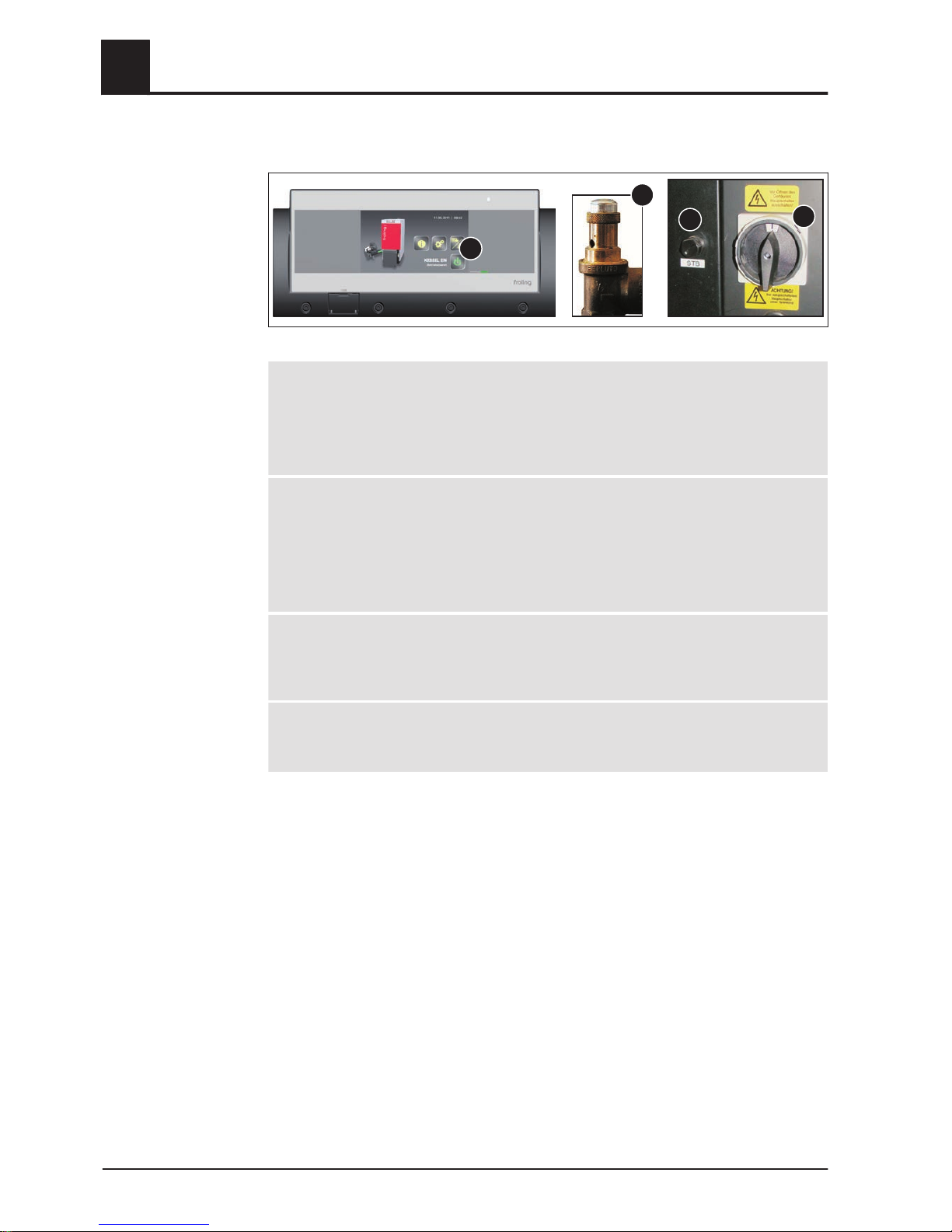
2.8 Safety devices
1
SV
3
2
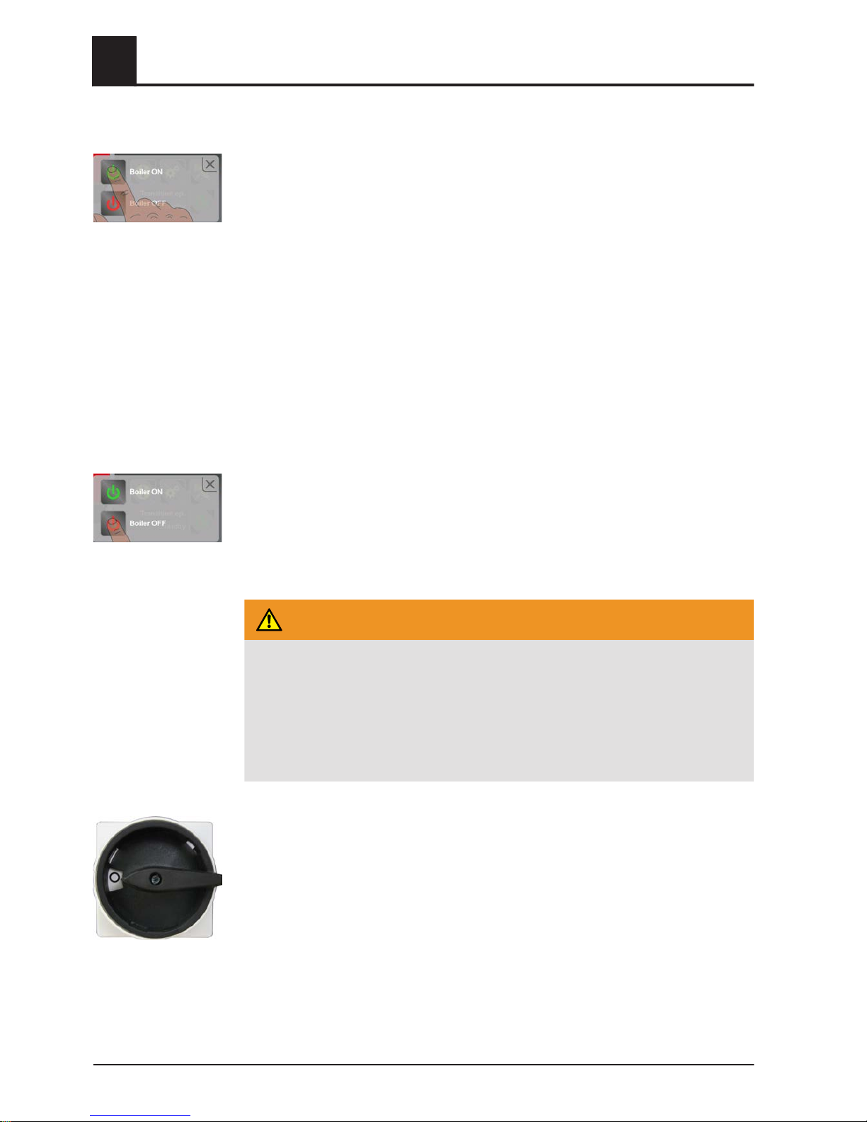
1 BOILER OFF
(switches off the boiler to prevent overheating)
❒ Tap “Boiler off”
➥ Automatic mode is switched off
➥ Control system follows the boiler shut-down procedure
➥ Pumps continue to run
2 MAIN SWITCH
(switches off the power supply)
Before carrying out work on/in the boiler:
❒ Tap “Boiler off”
➥ Automatic mode is switched off
➥ Control system follows the boiler shut-down procedure
❒ Switch off the main switch and let the boiler cool down
3 SAFETY TEMPERATURE LIMITER (STL)
(protection against overheating)
The STL switches off the combustion system when the boiler reaches 105°C. The
pumps continue to run. Once the temperature falls below approx. 75°C, the STL can
be reset mechanically.
SV SAFETY VALVE
(protection against overheating/excess pressure)
When the boiler pressure reaches a maximum of 3 bar, the safety valve opens and the
heated water is blown off in the form of steam.
2
Safety
Safety devices
16 Froling GesmbH | A-4710 Grieskirchen, Industriestraße 12 | www.froeling.com

2.9 Residual risks
WARNING
When touching hot surfaces:
Severe burns are possible on hot surfaces and the flue gas pipe!
When work is carried out on the boiler:
❒ Shut down the boiler in a controlled way (operating status "Boiler off") and al‐
low it to cool down
❒ Protective gloves must generally be worn for work on the boiler, and it should
only be operated using the handles provided
❒ Insulate the flue pipes or simply avoid touching them during operation.
WARNING
When inspecting and cleaning the boiler with the main switch on:
Serious injuries possible due to automatic boiler startup!
Before inspection and cleaning work in/on the boiler:
❒ Switch the boiler off by tapping “Boiler off”
The boiler follows the shutdown procedure and switches to "Boiler off“ mode
❒ Allow boiler to cool for at least 1 hour
❒ Switch off the main switch and take precautions to prevent accidental switch‐
ing on.
WARNING
If non-permitted fuel types are used:
Non-standard fuels can cause serious faults in combustion (e.g. spontaneous
combustion of carbonisation gases / flash fires) which can lead to serious acci‐
dents!
Take the following precautions:
❒ Only use fuels specified in the "Permitted fuels" section of these operating in‐
structions.
Safety
2
Residual risks
Operating Instructions T4 24-150 (Touch) | B0830113_en 17

2.10 Emergency procedure
2.10.1 Overheating of the system
If the system overheats and the safety devices fail, proceed as follows:
NOTICE! Do not under any circumstances switch off the main switch or disconnect the
power supply.
❒
Keep all the doors on the boiler closed
❒ Switch boiler off by tapping “Boiler OFF”
❒ Open all mixing valve taps, switch on all pumps.
➥ The Froling heating circuit control performs this function in automatic operation.
❒ If a third-party controller is used, carry out the appropriate measures to activate
the mixer taps and pumps manually.
❒ Leave the boiler room and close the door
❒ Open any available radiator thermostat valves
If the temperature does not drop:
❒ Contact the installer or Froling customer services
⇨ See "Addresses" [page 42]
2.10.2 Smell of flue gas
DANGER
If you smell flue gas in the boiler room:
Inhaling toxic flue gas can be fatal!
If you smell flue gas in the room where the boiler is installed:
❒ Keep all the doors on the boiler closed
❒ Shut down the boiler according to procedure
❒ Ventilate the room where the boiler is installed
❒ Close the fire door and doors to living areas
2
Safety
Emergency procedure
18 Froling GesmbH | A-4710 Grieskirchen, Industriestraße 12 | www.froeling.com

2.10.3 Fire in the system
DANGER
In case of fire in the system:
Risk of death by fire and poisonous gases
Emergency procedure in case of fire:
❒ Leave the boiler room
❒ Close the doors
❒ Inform the fire department
Safety
2
Emergency procedure
Operating Instructions T4 24-150 (Touch) | B0830113_en 19

3 Operating the System
3.1 Assembly and initial startup
Assembly, installation and initial startup of the boiler must only be carried out by quali‐
fied staff, and these procedures are described in the accompanying assembly instruc‐
tions.
NOTICE! See assembly instructions for the T4
NOTICE
Optimum efficiency and efficient, low-emission operation can only be guaranteed
if the system is set up by trained professionals and the standard factory settings
are observed.
Take the following precautions:
❒
Initial startup should be carried out with an authorised installer or with Froling
customer services
The individual steps for initial start-up are explained in the operating instructions for
the controller
NOTICE! See operating instructions for the Lambdatronic H 3200 T4
The customer is responsible for ensuring the following prior to initial start-up of the
system by Froling customer services:
▪
Electrical installation
▪ Installation of water pipes
▪ Flue gas connection including all insulation work
▪ Work must comply with local fire protection regulations
▪ The necessary "dry run" of the system means that the discharge system must be
empty at the start of initial startup. Fuel must be available, however, so that the
discharge system can be filled once the system is released.
▪ It is essential that the electrician who has carried out the installation work is availa‐
ble when starting up the system for the first time to make any changes to the wir‐
ing which may become necessary.
▪ During initial start-up, operating staff are shown how to use the boiler. It is impera‐
tive for proper handover of the product that those involved are present as this is a
one-off opportunity.
NOTICE
If condensation escapes during the initial heat-up phase, this does not indicate a
fault.
❒
Tip: If this occurs, clean up using a cleaning rag.
3
Operating the System
Assembly and initial startup
20 Froling GesmbH | A-4710 Grieskirchen, Industriestraße 12 | www.froeling.com

3.2 Filling/refilling the store with fuel
When filling the store you should always ensure that you are using the right fuel:
⇨ See "Permitted fuels" [page 11]
3.2.1 Loading of fuel for a partially emptied store with rotary agitator
If there is still sufficient fuel in the store (the head of the rotary agitator is completely
covered with fuel and the rotary agitator arms are not extended), the store can be fil‐
led:
❒
Load the fuel at the filling opening
3.2.2 Loading wood chips in an empty store (not under pressure)
NOTICE! If the head of the rotary agitator is already free of material and the arms /
spring blades are extended, then the feeder unit must be active during the filling proc‐
ess.
❒
Activate “Extra heating” mode in the quick menu
❒ Load a small quantity of wood chips and wait until the arms / spring blades are
touching the head of the rotary agitator (approx. 2 revolutions)
❒ Only then should you load the remaining material
Operating the System
3
Filling/refilling the store with fuel
Operating Instructions T4 24-150 (Touch) | B0830113_en 21

3.2.3 Blowing in pellets for a store with pellet screw
❒ Switch off the boiler by tapping “Boiler off” at the mode icon and allow to cool for at
least two hours
❒
Close all openings to the store to seal out dust
❒ Blow the fuel into the store
3.2.4 Blowing in fuel for a partially emptied store with rotary agitator
If there is still sufficient fuel in the store (the head of the rotary agitator is completely
covered with fuel and the rotary agitator arms are not extended), the store can be filled
as follows:
❒
Switch off the boiler by tapping “Boiler off” at the mode icon and allow to cool for at
least two hours
❒ Close all openings to the store to seal out dust
❒ Blow the fuel into the store
3.2.5 Blowing in fuel for an empty store with rotary agitator
3
Operating the System
Filling/refilling the store with fuel
22 Froling GesmbH | A-4710 Grieskirchen, Industriestraße 12 | www.froeling.com

NOTICE! If the head of the rotary agitator is already free of material and the arms /
spring blades are extended, then the store must not be filled until the following actions
have been taken:
❒
Switch off the boiler by tapping “Boiler off” at the mode icon and switch off main
switch
❒ Turn off the main switch on the expansion switch cabinet (if installed)
❒ Distribute any fuel remaining in the store (in corners, against walls) over the head
of the rotary agitator with your hands
➥ Follow the instructions on working in the fuel store!
NOTICE! Refer to the notice (supplied with the boiler) at the entrance to the store
After working in the store:
❒ Turn on the main switch on the boiler and on the expansion switch cabinet (if in‐
stalled)
❒ Activate “Extra heating” mode in the quick menu
❒ Wait until the arms / spring blades are touching the head of the rotary agitator (ap‐
prox. 2 revolutions)
❒ Switch off the boiler by tapping “Boiler off” at the mode icon and allow to cool for at
least two hours
❒ Close all openings to the store to seal out dust
❒ Blow the fuel into the store
If the fuel store is completely empty and there is no residual fuel to redistribute:
❒ Contact Froling and seek advice before filling the fuel store
⇨ See "Address of manufacturer" [page 42]
3.3 Heating up the boiler
NOTICE
Do not modify the factory settings!
Changing the system's factory settings can be detrimental to efficiency and emis‐
sions of the system.
3.3.1 Switching on the power supply
❒ Turn on the main switch
➥ There is voltage at all of the boiler's components
➥ When the control has completed the system start, the boiler is ready for opera‐
tion
Operating the System
3
Heating up the boiler
Operating Instructions T4 24-150 (Touch) | B0830113_en 23
3.3.2 Switching on the boiler
❒ Switch the boiler on by tapping “Boiler ON”
➥ Automatic mode is active
➥ The heating system is controlled via the controller according to the selected
mode in automatic mode
❒
For other modes press the relevant function key
➥ Information on function keys in the relevant operating instructions for the
"Lambdatronic H 3200 T4" boiler controller
3.3.3 Controlling the boiler
Please see the relevant operating instructions for the "Lambdatronic H 3200 T4" boiler
controller for the necessary control steps, as well as displaying and modifying parame‐
ters
3.3.4 Switching off the boiler
❒ Switch boiler off by tapping “Boiler OFF”
➥ The boiler follows the shutdown program and switches to "
Boiler off" status
➥ The combustion unit is switched off, the chamber discharge unit and the entire
hydraulic system remain active
3.3.5 Switching off the power supply
WARNING
When turning off the main switch in automatic mode:
Serious combustion faults leading to serious accidents are possible.
Before turning off the main switch:
❒ Switch boiler off by tapping “Boiler OFF”
➥ The boiler follows the shutdown procedure and switches to "Boiler off“ sta‐
tus after the cleaning cycle
❒ Turn off the main switch
➥ Boiler controller is switched off
➥ The components powered via the control cabinet are powered down
➥ CAUTION: The expansion switch cabinet, which has its own power supply, is
still live.
NOTICE! Frost protection function is no longer active!
3
Operating the System
Heating up the boiler
24 Froling GesmbH | A-4710 Grieskirchen, Industriestraße 12 | www.froeling.com
4 Boiler Servicing
4.1 General information on servicing
DANGER
When working on electrical components:
Risk of electrocution!
When work is carried out on electrical components:
❒ Only have work carried out by a qualified electrician
❒ Observe the applicable standards and regulations
➥ Work must not be carried out on electrical components by unauthorised
people
WARNING
When inspecting and cleaning the boiler with the main switch on:
Serious injuries possible due to automatic boiler startup!
Before inspection and cleaning work in/on the boiler:
❒ Switch the boiler off by tapping “Boiler off”
The boiler follows the shutdown procedure and switches to "Boiler off“ mode
❒ Allow boiler to cool for at least 1 hour
❒ Switch off the main switch and take precautions to prevent accidental switch‐
ing on.
WARNING
During inspection and cleaning work to the hot boiler:
Hot parts and the flue gas pipe can cause serious burns!
Take the following precautions:
❒ It should be standard practice to wear protective gloves when working on the
boiler.
❒ Only operate the boiler using the handles provided
❒ Before starting any maintenance work activate “Service mode” in the quick
menu
➥ The boiler follows the shutdown procedure and switches to "Boiler off" sta‐
tus
❒ Allow boiler to cool for at least 1 hour
❒ After maintenance has been carried out switch the boiler on in the desired
mode.
➥ In service mode the boiler does not start automatically.
Boiler Servicing
4
General information on servicing
Operating Instructions T4 24-150 (Touch) | B0830113_en 25

WARNING
Incorrect inspection and cleaning:
Incorrect or insufficient inspection and cleaning of the boiler can cause serious
faults in combustion (e.g. spontaneous combustion of carbonisation gases / flash
fires) and this can lead to serious accidents and damage!
Take the following precautions:
❒ Clean the boiler following the instructions in the instruction manual. Follow the
boiler operating instructions.
NOTICE
We recommend that you keep a maintenance book in accordance with ÖNORM
M7510 of the Technical Directive for Fire Prevention (TRVB)
4
Boiler Servicing
General information on servicing
26 Froling GesmbH | A-4710 Grieskirchen, Industriestraße 12 | www.froeling.com

4.2 Inspection and cleaning
❒ Regular cleaning of the boiler extends its life and is a basic requirement for
smooth running.
❒
Recommendation: use an ash vacuum for cleaning.
4.2.1 Inspection
Checking the system pressure
❒ Check the system pressure on the pressure gauge
➥ The value must be 20% above the pre-stressed pressure of the expansion tank
NOTICE! Check that the position of the pressure gauge and rated pressure of
the expansion tank match your installer's specifications!
If the system pressure decreases:
❒ Top up with water
NOTICE! If this happens frequently, the seal of the heating system is faulty! Inform
your installer
If large pressure fluctuations are observed:
❒ Ask an expert to inspect the expansion tank
Checking the safety valve
❒ Check the seal of the safety valve regularly and ensure that the valve is not dirty
NOTICE! Inspection work must be carried out in accordance with the manufactur‐
er’s instructions.
Checking the geared motors
❒ Carry out a visual inspection of the seal on all the geared motors in the system
➥ There should be no significant leakage of lubricant.
NOTICE! The presence of a few drops of lubricant may be normal. If there is
significant loss of lubricant, inform your installer or Froling customer services.
Boiler Servicing
4
Inspection and cleaning
Operating Instructions T4 24-150 (Touch) | B0830113_en 27
4.2.2 Cleaning
Emptying the ash container
The ash container must be emptied at appropriate intervals depending on energy re‐
quirements and fuel quality.
If the ash container is full before you check the ash level, the warning “ash box
full, please empty” will appear on the display.
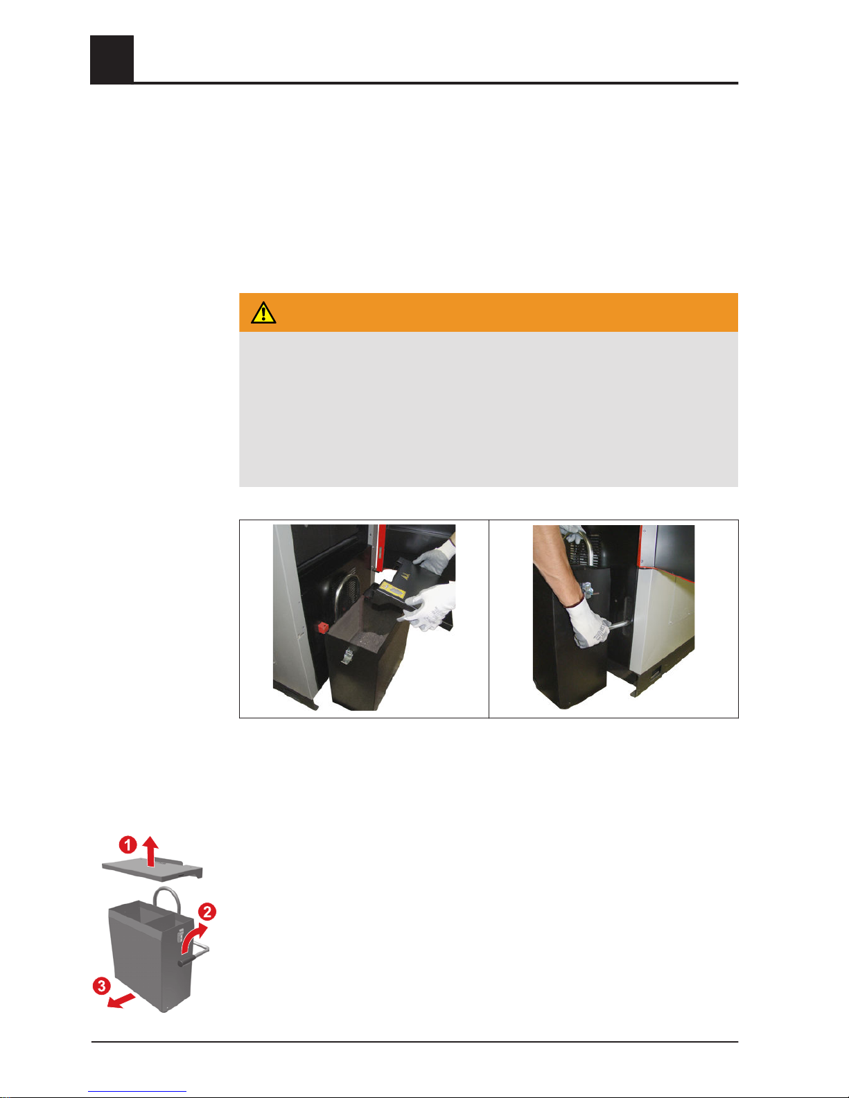
WARNING
When removing the ash container cover during operation:
False air infiltration via the ash screw duct can lead to uncontrolled combustion
and the risk of accidents.
Before checking the ash level / emptying the ash container:
❒ Switch off the boiler by tapping “Boiler off”
➥ The boiler follows the shutdown procedure and switches to "Boiler off" sta‐
tus.
In “Boiler off” operating status:
❒
Open the insulated door
NOTICE! Note the sticker on the cover of the ash container!
❒
Open the side clamps and remove the ash container cover (1)
❒ Check the ash level in both chambers
➥ If either of the two chambers is more than two thirds full, empty the ash con‐
tainer
❒ Open the ash container clamp using the locking lever (2)
❒ Remove the ash container from the boiler (3)
4
Boiler Servicing
Inspection and cleaning
28 Froling GesmbH | A-4710 Grieskirchen, Industriestraße 12 | www.froeling.com

❒
Place the transport cover over the openings of the ash container
❒ Put on the ash container cover, pull out the transport lever and take the ash con‐
tainer to the emptying point
After emptying the ash container:
❒ Replace the ash container in the boiler and clamp with the locking lever
❒
Replace the cover and secure with the clamps
➥ Make sure that the pin (2) is inserted in the limit switch (1) correctly
Boiler Servicing
4
Inspection and cleaning
Operating Instructions T4 24-150 (Touch) | B0830113_en 29

4.2.3 Recurrent check and cleaning
The boiler must be cleaned and inspected at appropriate intervals depending on the
service hours and fuel quality.
For fuels with a low ash content (standard wood chips), annual cleaning and inspec‐
tion (2000 to 2500 service hours) is usually sufficient. For less efficient fuels and fuels
with a high ash content (indicated by short emptying intervals for the ash container),
the work should be carried out more frequently accordingly.
WARNING
Inspection and cleaning work with the boiler switched on
Serious injuries from automatic startup of the boiler and severe burns from hot
parts and the flue gas pipe are possible.
Therefore:
❒ Only carry out work on the boiler when the main switch is turned off
❒ Always wear protective gloves when working on the boiler
❒ Only operate the boiler using the handles provided
❒ Follow the procedure below when starting and finishing inspection and clean‐
ing work
Before starting inspection and cleaning work
❒ Switch off the boiler by tapping “Boiler off”
➥ Boiler shuts down and switches to "Boiler off” status
❒ Allow boiler to cool for at least 1 hour
❒ On the control, go to the "Manual operation" menu
NOTICE! See operating instructions for boiler controller Lambdatronic H 3200 T4
❒ Use the DOWN arrow to navigate to the “Tip drive” parameter
❒ Set parameter to “ON”
➥ Combustion grate tips
❒ Turn off the main switch
After inspection and cleaning work
❒ Turn on the main switch
➥ Combustion grate previously opened manually now closes automatically and
the boiler switches to “Boiler off” status
❒ Activate “service mode” in the quick menu
➥ The boiler starts the cleaning module and removes any remaining ash in the
combustion chamber
➥ Once self-cleaning is finished the boiler switches to "Boiler off" status.
4
Boiler Servicing
Inspection and cleaning
30 Froling GesmbH | A-4710 Grieskirchen, Industriestraße 12 | www.froeling.com

Cleaning the combustion chamber
❒
Open the insulated door and loosen the screw connections on the combustion
chamber door
❒ Open the combustion chamber door
❒
Use a small shovel or the like (ash vacuum recommended) to remove any ash
from the combustion chamber
➥ Do not throw the ash onto the grate
❒
Remove the burn-out opening
❒ Remove the dirt on the burn-out opening with a brush
❒ Remove ash build-up on the side walls using the ash scraper
Boiler Servicing
4
Inspection and cleaning
Operating Instructions T4 24-150 (Touch) | B0830113_en 31
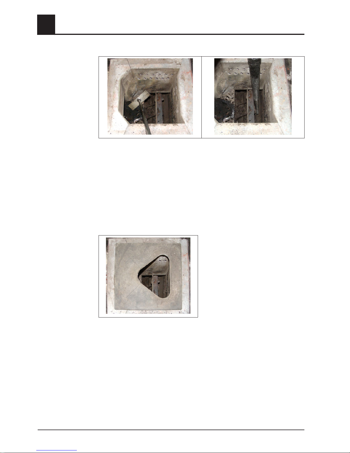
❒
Clean the firebrick in the combustion chamber and combustion grate with ash
scraper
❒ Remove any ash build-up and ash on the baffles and under the grate using ash
vacuum
❒ Carry out a visual inspection of the firebrick for damage
❒ Check the combustion grate for cracks and deformation
➥ Small cracks and deformations are not indicative of a fault. Only when entire
parts of the grate are at risk of breaking, should you stop using the boiler. In‐
form Froling customer services if this is the case!
❒
Install the burn-out opening
➥ The opening must be facing the fuel infeed side!
4
Boiler Servicing
Inspection and cleaning
32 Froling GesmbH | A-4710 Grieskirchen, Industriestraße 12 | www.froeling.com

Cleaning the heat-exchanger and flue gas collection chamber
❒
Removing the insulating cover and the insulating mat
❒
Loosen the lock nut on the star-shaped screw knob
❒ Unlock the cover by turning the star-shaped screw knob and remove
Boiler Servicing
4
Inspection and cleaning
Operating Instructions T4 24-150 (Touch) | B0830113_en 33
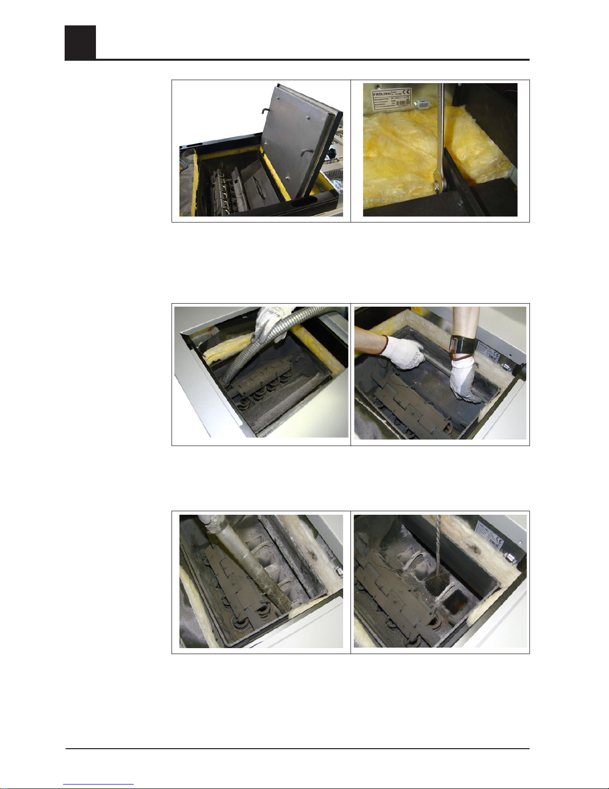
❒
Unlock the cover by turning the star-shaped screw knob and open
In the case of low down boiler rooms, you can remove the heat exchanger cover:
❒ Undo the screw connections on the hinge of the cover and remove the cover
❒
Clean the flue gas collection chamber with an ash vacuum
❒ Pull out the guide plate(s)
❒ Remove the ash under the guide plate with an ash vacuum
❒ Clean the heat exchanger pipes with the cleaning brush provided
➥ Push the cleaning brush right the way through before taking it out again!
❒ After cleaning, reassemble the dismantled components in the reverse order
For T4 60 – 150
4
Boiler Servicing
Inspection and cleaning
34 Froling GesmbH | A-4710 Grieskirchen, Industriestraße 12 | www.froeling.com

Cleaning the flue gas temperature sensor
❒
Release the retaining screw and take the flue gas temperature sensor (AF) out of
the flue gas pipe
❒ Wipe the flue gas temperature sensor with a clean cloth
❒ Push in the flue gas temperature sensor until about 20 mm of the sensor remains
protruding from the bushing and secure with fixing screw
Cleaning the flue gas pipe
❒ Switch off the induced draught fan
➥ This prevents damage to the fan from the cleaning brush
❒ Remove the inspection cover on the connecting pipe
❒ Clean the connecting pipe between the boiler and chimney with a chimney sweep‐
ing brush
➥ Depending on the layout of the flue gas pipes and the chimney draught, clean‐
ing once a year may not be enough!
Checking the seal on the doors
D
❒
Close the relevant door and check its seal
❒ Check the seal (D) for perfect alignment on the door frame
➥ Imprint in the seal
❒ If the seal is black or the imprint is broken:
➥ The seal is no longer guaranteed. Tighten the door latches or replace the seal
Boiler Servicing
4
Inspection and cleaning
Operating Instructions T4 24-150 (Touch) | B0830113_en 35
Checking the draught controller flap
❒ Check that the draught controller flap moves freely
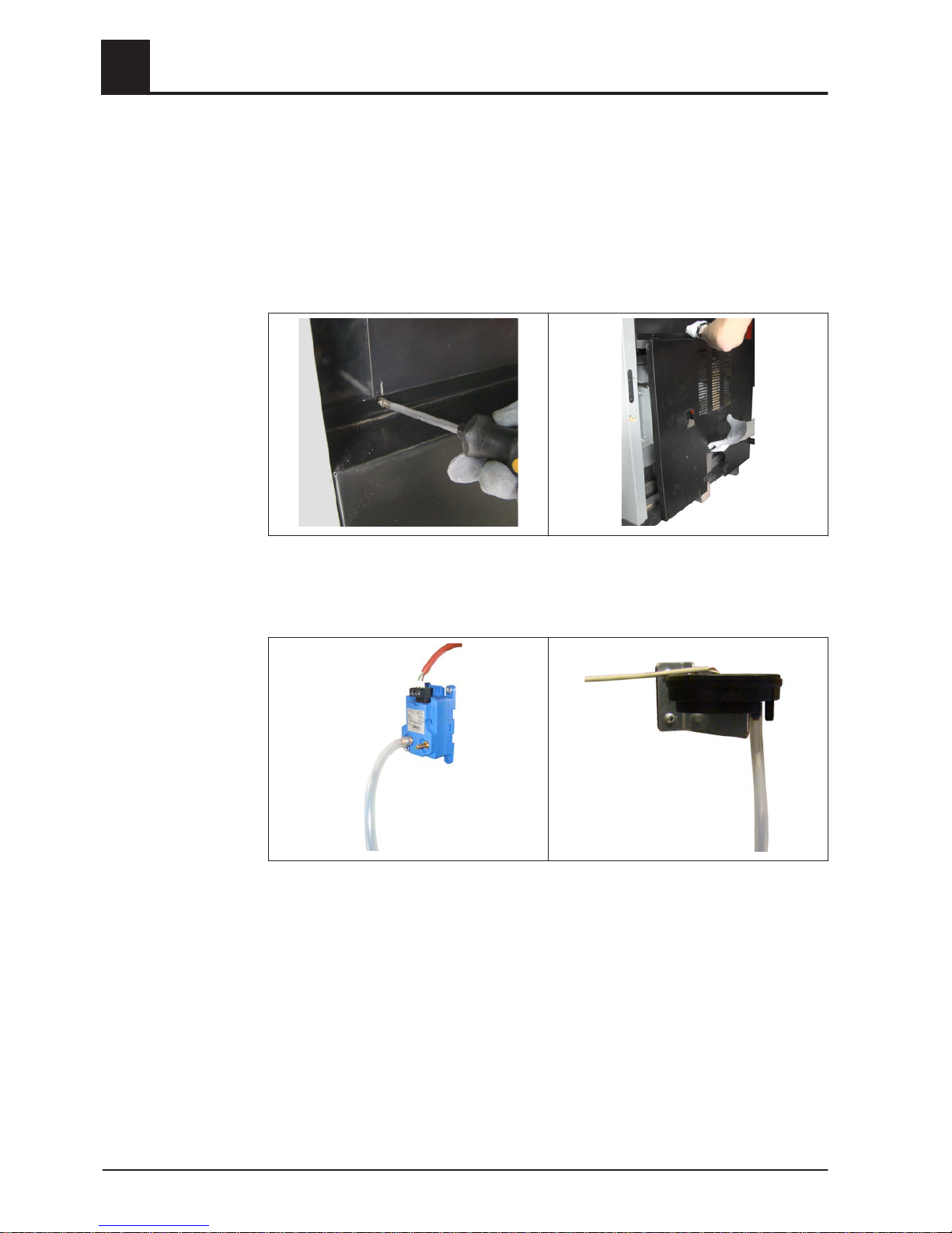
Cleaning the measurement line of the underpressure controller
❒ Open the insulated door and remove the ash box
⇨ See "Emptying the ash container" [page 28]
❒
Remove the left and right screws on the front cover plate
❒ Slide the cover plate up and remove
❒
Loosen the twin wire clamp with pliers and remove the measurement line
4
Boiler Servicing
Inspection and cleaning
36 Froling GesmbH | A-4710 Grieskirchen, Industriestraße 12 | www.froeling.com

❒
Clean the measurement line with gentle compressed air
➥ WARNING! Do not direct compressed air into under-pressure sensor cartridge!
This could damage it!
❒ After cleaning, refit the measurement line (port “-”)
Boiler Servicing
4
Inspection and cleaning
Operating Instructions T4 24-150 (Touch) | B0830113_en 37

4.3 Emissions measurement by chimney sweep or regulatory body
Various legal regulations stipulate that heating systems must be inspected periodical‐
ly. In Germany this is regulated by the First Federal Emissions Protection Ordinance
(BimSchV) in the last amended version, and in Austria by various state laws. The boil‐
er must always be cleaned 2-3 heating days prior to measurement. It is important to
ensure that there is adequate heat consumption on the day of the measurement. (e.g.
storage tank must be able to take heat for the duration of the measurement).
4.3.1 Measurement at nominal load
❒ For the highest possible heat consumption:
▪
Make sure that heating pumps are switched on
▪ Open mixing valves and radiator valves
▪ Set the DHW tank loading time to the current time
▪ Set the boiler temperature setpoint to 85°C
NOTICE! Chimney-sweep mode performs this function
Activate chimney-sweep mode
❒ Activate “Chimney-sweep mode” in the quick menu
➥ The chimney sweeper program is started. The system is operated for 45 mi‐
nutes at nominal load. For this purpose the maximum boiler and heating circuit
flow temperature and DHW tank loading are released.
Permitted measurement parameters:
▪ Flue gas temperature at approx. 140°C
(+/- 20°C depending on the cleanliness of the boiler)
▪ O2 content of the flue gas between 8 and 12%
(corresponds to a CO2 content of between 13 and 19%)
▪ Boiler temperature above 65°C
4.3.2 Measurement at partial load (if necessary)
❒ For heat consumption:
▪
Make sure that heating pumps are switched on
▪ Open mixing valves and radiator valves
▪ Set the DHW tank loading time to the current time
❒ Force partial load:
❒ After measuring at nominal load, lower the boiler temperature setpoint by 5°C
Permitted measurement parameters:
▪ Flue gas temperature at approx. 100°C
(+/- 20°C depending on the cleanliness of the boiler)
▪ O2 content of the flue gas between 10 and 14%
(corresponds to a CO2 content of between 7 and 11%)
▪ Boiler temperature above 65°C
❒ After the measurement all adjusted parameters (e.g. DHW tank loading times,
etc.) must be reset to their original value.
4
Boiler Servicing
Emissions measurement by chimney sweep or regulatory body
38 Froling GesmbH | A-4710 Grieskirchen, Industriestraße 12 | www.froeling.com

4.4 Maintenance agreement / Customer service
NOTICE! We recommend a yearly inspection by Froling customer services or an au‐
thorised partner (third party maintenance).
Regular maintenance and servicing by a heating specialist will ensure a long, troublefree service life for your heating system. It will ensure that your system stays environ‐
mentally-friendly and operates efficiently and cost-effectively.
In the course of this maintenance the entire system is inspected and optimised, partic‐
ularly regulation and control of the boiler. The emission measurement carried out can
also be used to draw conclusions about the combustion performance of the boiler.
For this reason, FROLING offers a service agreement, which optimises operating
safety. Please see the details in the accompanying guarantee certificate.
Your Froling customer service office will also be happy to advise you.
NOTICE
All national and regional regulations relating to regular testing of the system must
be observed. Please be advised that, in Austria, commercial systems with a rated
heat output of 50 kW or more must be regularly tested at yearly intervals in ac‐
cordance with the Heating Plant Regulations (Feuerungsanlagen-Verordnung).
4.5 Replacement parts
With Froling original replacement parts in your boiler, you are using parts that match
perfectly. As the parts fit together so well, installation times are shortened and a long
service life is maintained.
NOTICE
Installing non-original parts will invalidate the guarantee.
❒
Only replace components or parts with original replacement parts
4.6 Disposal information
4.6.1 Disposal of the ash
❒ The ash should be disposed of in accordance with waste management regula‐
tions.
4.6.2 Disposal of system components
❒ Ensure that the system is disposed of in an environmentally friendly way in ac‐
cordance with waste management regulations.
❒
You can separate and clean recyclable materials and send them to a recycling
centre.
❒ The combustion chamber must be disposed of as builders' waste.
Boiler Servicing
4
Maintenance agreement / Customer service
Operating Instructions T4 24-150 (Touch) | B0830113_en 39
5 Troubleshooting
5.1 General fault with power supply
Error characteristics Cause of error Elimination of error
Nothing is shown on the dis‐
play
No power to the controller
General power failure
Main switch is turned off
FI circuit breaker or line pro‐
tection is switched off
Faulty fuse in the controller
Turn on the main switch
Switch on the FI circuit break‐
er or line protection
Replace the fuse – note the
amperage (10AT)
5.1.1 Behaviour of system after a power failure
When the power supply has been restored, the boiler returns to the previous mode
and is controlled according to the specified program.
❒ After a power failure, check whether the STL (high-limit thermostat) has tripped.
❒ Keep the doors of the boiler closed during and after the power failure, at least until
the induced draught fan automatically starts up again.
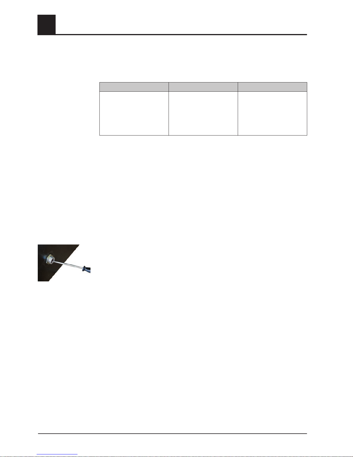
5.2 Excessive temperature
The high-limit thermostat (STL) shuts down the boiler when it reaches a temperature
of max. 105°C. The pumps continue to run.
Once the temperature falls below approx. 75°C, the STL (high-limit thermostat) can be
reset mechanically:
❒
Unscrew the cap on the STL (high-limit thermostat)
❒ Unlock the STL (high-limit thermostat) by pressing with a screwdriver
5
Troubleshooting
General fault with power supply
40 Froling GesmbH | A-4710 Grieskirchen, Industriestraße 12 | www.froeling.com

5.3 Faults with fault message
If a fault has occurred and has not yet been cleared:
❒
Status LED indicates the nature of the fault
- Orange flashing: Warning
- Red flashing: Error or alarm
❒ A fault message is shown on the display
The term "fault" is a collective term for warnings, errors and alarms. The boiler reacts
differently to the three types of message:
WARNING In case of warnings the boiler initially continues controlled opera‐
tion, giving the option of resolving the error quickly to prevent a
shutdown.
ERROR The boiler follows the shutdown procedure and remains in "Boil‐
er off" status until the problem is resolved.
ALARM An alarm triggers a system emergency stop. The boiler shuts
down immediately, the heating circuit controller and pumps re‐
main active.
5.3.1 Procedure for fault messages
The procedure in the case of a fault message, the causes of faults and procedure for
troubleshooting are described in the operating instructions for the boiler controller:
IMPORTANT! See operating instructions for the
Lambdatronic H 3200 - T4
5.3.2 Acknowledging a fault message
Trace and remove the fault and then:
❒
Tap the “Cancel” symbol
➥ Status LED constant or flashing green light (depending on operating status)
- Green constant: Boiler switched on
- Green flashing: Boiler switched off
Troubleshooting
5
Faults with fault message
Operating Instructions T4 24-150 (Touch) | B0830113_en 41

6 Appendix
6.1 Addresses
6.1.1 Address of manufacturer
FRÖLING
Heizkessel- und Behälterbau GesmbH
Industriestraße 12
A-4710 Grieskirchen
AUSTRIA
TEL 0043 (0)7248 606 0
FAX 0043 (0)7248 606 600
INTERNET www.froeling.com
6.1.2 Address of the installer
Stamp
6
Appendix
Addresses
42 Froling GesmbH | A-4710 Grieskirchen, Industriestraße 12 | www.froeling.com
 Loading...