

Froling S3 Turbo 18, S3 Turbo 28, S3 Turbo 45, S3 Turbo 36 Installation Instructions Manual
Installation Instructions
Firewood boiler S3 Turbo
Translation of the original German installation instructions for technicians
Read and follow the instructions and safety information!
Technical changes, typographical errors and omissions reserved!
M1080813_en | Edition 30/09/2013
Froeling GesmbH | A-4710 Grieskirchen, Industriestraße 12 | www.froeling.at

Table of Contents
1 General 4
2 Safety 5
2.1 Hazard levels of warnings 5
2.2 Qualification of assembly staff 6
2.3 Protective equipment for assembly staff 6
2.4 Design Information 7
2.4.1 Notes on standards 7
General standards for heating systems
7
Standards for structural and safety devices
7
Standards for heating water
7
Standards for permitted fuels
8
2.4.2 Installation and approval of the heating system 8
2.4.3 General information for installation room (boiler room) 8
2.4.4 Requirements for central heating water 9
2.4.5 Notes for using pressure maintenance systems 10
2.4.6 Return lift 10
2.4.7 Combination with storage tank 11
2.4.8 Chimney connection/chimney system 13
Draught limiter
13
Boiler data for planning the flue gas system
13
3 Technology 14
3.1 Dimensions 14
3.2 Components and connections 15
3.3 Technical specifications 16
4 Assembly 19
4.1 Materials supplied 19
4.1.1 Tools required 19
4.2 Positioning 20
4.2.1 Temporary storage 20
4.3 Setting up in the boiler room 21
4.3.1 Remove boiler from pallet 21
4.3.2 Moving the boiler in the boiler room 21
4.3.3 Minimum distances in the boiler room 22
4.4 Before Installation 22
4.4.1 Changing door stops (as needed) 22
Converting the fuel loading door
24
4.4.2 Fitting the door handles 25
4.4.3 Setting and checking the seal on the doors 26
Positioning the doors
27
4.5 Installing the boiler 28
4.5.1 Assembly overview 28
Insulation
28
Air duct system
30
WOS system S3 Turbo 18-28
32
WOS system S3 Turbo 36-45
34
Table of Contents
2 Froeling GesmbH | A-4710 Grieskirchen, Industriestraße 12 | www.froeling.at

4.5.2 Installing the flue gas pipe nozzle 36
4.5.3 Fit the induced draught fan 36
4.5.4 Installing the pneumatic rods for the primary and secondary air 36
4.5.5 Final steps before insulating 38
4.5.6 Installing the insulation 39
4.5.7 Installing the door switch 41
4.5.8 Installing the back panel 41
4.5.9 Aligning the insulation and attaching the controller 42
4.5.10 Installing the cleaning port door and blank cover 44
4.5.11 Installing the insulated door 44
4.5.12 Fitting the sensors 47
4.5.13 Install the broadband probe (only with S-Tronic Lambda) 48
4.5.14 Installing the WOS system 49
4.5.15 Installing the manual controller/servo-motors 51
Mounting the manual controller (with S-Tronic/S-Tronic Plus control)
51
Mounting the servo-motors (with S-Tronic Lambda control)
52
4.6 Power connection and wiring 54
4.6.1 S-Tronic control 54
Power connection
54
Hydraulic system
57
4.6.2 S-Tronic Plus / S-Tronic Lambda control 58
Power connection
58
Hydraulic system
58
4.6.3 Information on circulating pumps 59
4.6.4 Concluding work 59
4.7 Connecting the hydraulic safety devices 61
5 Start-up 62
5.1 Before commissioning / configuring the boiler 62
5.2 Initial startup 63
5.2.1 Permitted fuels 63
Firewood
63
5.2.2 Fuels permitted under certain conditions 63
Wood briquettes
63
5.2.3 Non-permitted fuels 64
5.2.4 Heating up for the first time 64
Boiler with Lambda control
65
Boiler with manual controller
65
6 Decommissioning 68
6.1 Mothballing 68
6.2 Disassembly 68
6.3 Disposal 68
7 Appendix 69
7.1 Pressure equipment regulation 69
7.2 Technical specifications - S3 Turbo with partial load values 70
7.3 Addresses 71
7.3.1 Address of manufacturer 71
7.3.2 Address of the installer 71
Table of Contents
Installation Instructions S3 Turbo | M1080813_en 3

1 General
Thank you for choosing a quality product from Froling. The product features a state-ofthe-art design and conforms to all currently applicable standards and testing guide‐
lines.
Please read and observe the documentation provided and always keep it close to the
system for reference. It contains important safety information and all the operation and
maintenance specifications needed to operate the system safely, properly, environ‐
mentally friendly and cost-effectively.
The constant further development of our products means that there may be minor dif‐
ferences from the pictures and content. If you discover any errors, please let us know:
doku@froeling.com
Subject to technical change.
The EC Declaration of Conformity is only valid in conjunction with a delivery certificate,
which has been filled in correctly and signed as part of the commissioning process.
The original document remains at the installation site. Commissioning installers or
heating engineers are requested to return a copy of the delivery certificate together
with the guarantee card to Froling. On commissioning by FROLING Customer Service
the validity of the delivery certificate will be noted on the customer service record.
Issuing a delivery cer‐
tificate
1
General
4 Froeling GesmbH | A-4710 Grieskirchen, Industriestraße 12 | www.froeling.at
2 Safety
2.1 Hazard levels of warnings
This documentation uses warnings with the following hazard levels to indicate direct
hazards and important safety instructions:
DANGER
The dangerous situation is imminent and if measures are not observed it will lead
to serious injury or death. You must follow the instructions!
WARNING
The dangerous situation may occur and if measures are not observed it will lead
to serious injury or death. Work with extreme care.
CAUTION
The dangerous situation may occur and if measures are not observed it will lead
to minor injuries or damage to property.
Safety
2
Hazard levels of warnings
Installation Instructions S3 Turbo | M1080813_en 5
2.2 Qualification of assembly staff
CAUTION
Assembly and installation by untrained personnel:
Risk of personal injury and damage to property.
During assembly and installation:
❒ Observe the instructions and information in the manuals
❒ Only allow trained staff to carry out assembly and installation
Assembly, installation, initial startup and servicing must always be carried out by quali‐
fied personnel:
- Heating technician / building technician
- Electrical installation technician
- Froling customer services
The assembly staff must have read and understood the instructions in the documenta‐
tion.
2.3 Protective equipment for assembly staff
You must ensure that staff have the protective equipment specified by accident pre‐
vention regulations.
▪ For transportation, setup and assembly:
- suitable workwear
- protective gloves
- sturdy shoes
2
Safety
Qualification of assembly staff
6 Froeling GesmbH | A-4710 Grieskirchen, Industriestraße 12 | www.froeling.at

2.4 Design Information
2.4.1 Notes on standards
The system must be installed and commissioned in accordance with the local fire and
building regulations. The following standards and regulations should always be ob‐
served:
General standards for heating systems
EN 303-5 Boilers for solid fuels, manually and automatically fed combus‐
tion systems, nominal output up to 300 kW
EN 12828 Heating systems in buildings - Design of water-based heating
systems
EN 13384-1 Chimneys - Thermal and fluid dynamic calculation methods
Part 1: Chimneys serving one appliance
ÖNORM M 7510-1 Guidelines for checking central heating systems
Part 1: General requirements and one-off inspections
ÖNORM M 7510-4 Guidelines for checking central heating systems
Part 4: Simple check for heating plants for solid fuels
Standards for structural and safety devices
ÖNORM H 5170 Heating installation - Requirements for construction and safety
engineering, as well as fire prevention and environmental pro‐
tection
Standards for heating water
ÖNORM H 5195-1 Prevention of damage by corrosion and scale formation in
closed warm water heating systems at operating temperatures
up to 100 °C (Austria).
VDI 2035 Sheet 1 Prevention of damage in water heating systems - Scale forma‐
tion in domestic water heating systems and hot water heating
systems (Germany)
SWKI 97-1 Water quality for heating, steam, cooling and air conditioning
systems (Switzerland)
D.P.R. no. 412 Regulations for the planning, installation, running/operation and
maintenance of heating systems in buildings to reduce energy
consumption with reference to Article 4, Comma 4 of the Legis‐
lative Decree of 9 January 1991, No. 10 (Italy)
Safety
2
Design Information
Installation Instructions S3 Turbo | M1080813_en 7

Standards for permitted fuels
EN 14961-3 Solid bio-fuel - Fuel specifications and classes
Part 2: Wood briquettes for non-industrial use
EN 14961-5 Solid bio-fuel - Fuel specifications and classes
Part 5: Firewood for non-industrial use
1. BImSchV First Ordinance of the German Federal Government for imple‐
mentation of the Federal Emission Protection Law, BGBl. I P.
491, in the applicable version.
2.4.2 Installation and approval of the heating system
The boiler should be operated in a closed heating system. The following standards
govern the installation:
ÖNORM / DIN EN 12828 Heating Systems in Buildings
NOTICE! Each heating system must be officially approved.
The appropriate supervisory authority (inspection agency) must always be informed
when installing or modifying a heating system, and authorisation must be obtained
from the building authorities:
Austria: Inform the civic/municipal building authorities.
Germany: Notify an approved chimney sweep and the building authorities.
2.4.3 General information for installation room (boiler room)
Boiler room characteristics
▪ There must not be a potentially explosive atmosphere in the boiler room as the
boiler is not suitable for use in potentially explosive environments.
▪ The boiler room must be frost-free.
▪ The boiler does not provide any light, so the customer must provide sufficient light‐
ing in the boiler room in accordance with national workplace design regulations.
▪ When using the boiler over 2000 metres above sea level you should consult the
manufacturer.
▪ Danger of fire due to flammable materials.
No flammable materials should be stored near the boiler. Flammable objects (e.g.
clothing) must not be put on the boiler to dry.
▪ Damage due to impurities in combustion air.
Do not use any solvents or cleaning agents containing chlorine in the room where
the boiler is installed.
▪ Keep the air suction opening of the boiler free from dust.
Ventilation of the boiler room
Ventilation air for the boiler room should be taken from and expelled directly outside,
and the openings and air ducts should be designed to prevent weather conditions (foli‐
age, snowdrifts, etc.) from obstructing the air flow.
Note on standards
2
Safety
Design Information
8 Froeling GesmbH | A-4710 Grieskirchen, Industriestraße 12 | www.froeling.at

Unless otherwise specified in the applicable building regulations for the boiler room,
the following standards apply to the design and dimensions of the air ducts:
ÖNORM H 5170 - Construction and fire protection requirements
2.4.4 Requirements for central heating water
The following standards and guidelines apply:
Austria:
Germany:
Switzerland:
Italy:
ÖNORM H 5195-1
VDI 2035
SWKI 97-1
D.P.R. no. 412
NOTICE! Note on filling with make-up water: Always bleed the filling hose before con‐
necting, in order to prevent air from entering the system.
Observe the standards and also follow the recommendations below:
❒
Max. cumulative value for alkaline earth: 1.0 mmol/l or 100 mg/l (corresponds to
5.6 dH)
❒ Use softened water as the make-up water
❒ Avoid leaks and use a closed heating system to maintain water quality during op‐
eration
Note on standards
Note on standards
Safety
2
Design Information
Installation Instructions S3 Turbo | M1080813_en 9

2.4.5 Notes for using pressure maintenance systems
Pressure maintenance systems in hot-water heating systems keep the required pres‐
sure within predefined limits and balance out volume variations caused by changes in
the hot-water temperature. Two main systems are used:
Compressor-controlled pressure maintenance
In compressor-controlled pressure maintenance units, a variable air cushion in the ex‐
pansion tank is responsible for volume compensation and pressure maintenance. If
the pressure is too low, the compressor pumps air into the tank. If the pressure is too
high, air is released by means of a solenoid valve. The systems are built solely with
closed-diaphragm expansion tanks to prevent the damaging introduction of oxygen in‐
to the domestic hot water.
Pump-controlled pressure maintenance
A pump-controlled pressure maintenance unit essentially consists of a pressure-main‐
tenance pump, relief valve and an unpressurised receiving tank. The valve releases
hot water into the receiving tank if the pressure is too high. If the pressure drops below
a preset value, the pump draws water from the receiving tank and feeds it back into
the heating system. Pump-controlled pressure maintenance systems with open expan‐
sion tanks (e.g. without a diaphragm) introduce ambient oxygen via the surface of the
water, exposing the connected system components to the risk of corrosion. These
systems offer no oxygen removal for the purposes of corrosion control as required by
VDI 2035 and in the interests of corrosion protection should not be used.
2.4.6 Return lift
If the hot water return is below the minimum return temperature, some of the hot water
outfeed will be mixed in.
CAUTION
Risk of dropping below dew point/condensation formation if operated without re‐
turn temperature control.
Condensation water forms an aggressive condensate when combined with com‐
bustion residue, leading to damage to the boiler.
Take the following precautions:
❒ Regulations stipulate the use of a return temperature control.
➥ The minimum return temperature is 60 °C. We recommend fitting some
sort of control device (e.g. thermometer).
2
Safety
Design Information
10 Froeling GesmbH | A-4710 Grieskirchen, Industriestraße 12 | www.froeling.at

2.4.7 Combination with storage tank
Observe the regional regulations for using a storage tank!
Certain subsidy guidelines prescribe compulsory requirements for the installation of
storage tanks. Up-to-date information about individual subsidy guidelines can be found
at www.froeling.com.
Channelling the heat generated by the Firewood boiler to a storage tank, can bring
major advantages, including:
❒
better utilisation of fuel
❒ more user-friendly operation in terms of reloading intervals
❒ maximum independence from instantaneous heating requirements
❒ minimal dirt in boiler and flue gas system
As the boiler’s minimum continuous heat output is 30% above the nominal heat out‐
put, we as the boiler manufacturer are obliged under EN 303-5:2012, Section 4.4.6 to
advise that the Firewood boiler S3 Turbo must always be connected to a storage tank
with adequate storage capacity.
Certain countries have recommended storage capacities; these are listed below. The
specified values apply when the nominal heat output of the boiler corresponds to the
heating requirements of the building and a maximum of 50% of the nominal heat out‐
put can be dissipated to the building being heated under partial load conditions.
The storage tank capacity can be calculated according to EN 303-5:2012 using the fol‐
lowing formula:
VSp = 15TB x QN (1 - 0.3 x QH/Q
min
)
V
Sp
Q
N
T
B
Q
H
Q
min
Storage tank capacity in [l]
Nominal heat output of boiler in [kW]
Burn-off period of boiler in [h]
1)
Heating load of building in [kW]
Minimum heat output of boiler in [kW]
2)
1.Sample combustion times for various fuels are provided in the technical data
2.
The boiler’s minimum output is the lowest value of the output range in the technical data. If there is no minimum heat output specified, use
the nominal heat output (Q
min
= QN)
NOTICE! EN 303-5:2012 stipulates that the storage tank capacity is at least 300l!
According to the relevant Austrian laws governing energy technology, which are based
on Art. 15a B-VG "Agreement on protective measures for small furnaces" (2012):
No storage tank is required on manually fed biomass boilers that have been positively
tested at both nominal load and partial load (below 50% of nominal load) to ensure
they adhere to the emissions limits specified in that agreement.
General information
Austria
Safety
2
Design Information
Installation Instructions S3 Turbo | M1080813_en 11

Recommended storage tank capacity:
Unit S3 Turbo
18 - 28
S3 Turbo
36 - 45
Recommended storage tank capacity
1)
[l] 1700 3000
1.Values for calculating the capacity can be found in the technical data or the technical data with partial load inspection (if available)
The first BImSchV (Ordinance on small and medium-sized heating plants of 26 Janu‐
ary 2010, BGBl. I p. 38) stipulates a minimum water heat storage tank capacity of 55
litres per kilowatt of nominal heat output; a water heat storage tank with a capacity of
12 litres per litre of fuel loading chamber is recommended.
Recommended storage tank capacity:
Unit S3 Turbo
18 - 28
S3 Turbo
36 - 45
Recommended storage tank capacity
1)
[l] 1700 3000
1.Values for calculating the capacity can be found in the technical data or the technical data with partial load inspection (if available)
For the correct dimensions of the storage tank and the line insulation
(e.g. in accordance with ÖNORM M 7510 or guideline UZ37) please consult your installer or
Froling.
Germany
2
Safety
Design Information
12 Froeling GesmbH | A-4710 Grieskirchen, Industriestraße 12 | www.froeling.at

2.4.8 Chimney connection/chimney system
EN 303-5 specifies that the entire flue gas system must be designed to prevent, wher‐
ever possible, damage caused by seepage, insufficient feed pressure and condensa‐
tion. Please note in this respect that flue gas temperatures lower than 160K above
room temperature can occur in the permitted operating range of the boiler.
The flue gas temperatures (for clean systems) and additional flue gas values can be
found in the table below.
The connection between the boiler and the chimney system should be as short as
possible. The upward angle of the connection should not exceed 30° - 45°. Insulate
the connection. The entire flue gas system - chimney and connection - should be cal‐
culated in accordance with EN 13384-1.
Local regulations and other statutory regulations also apply.
NOTICE! The chimney must be authorised by a smoke trap sweeper or chimney
sweep.
Draught limiter
The installation of a draught limiter is recommended.
NOTICE! Install the draught limiter directly under the mouth of the flue line, as the
pressure is constantly low at this point.
Boiler data for planning the flue gas system
Description S3 Turbo
18 28 36 45
Flue gas temperature at nominal load °C 150 170 150 170
Flue gas temperature at partial load - 120 110 120
Flue gas mass flow at nominal load kg/s 0.016 0.022 0.026 0.033
Flue gas mass flow at partial load - 0.011 0.013 0.016
Required feed pressure at nominal load mbar 0.08 0.08 0.08 0.08
Required feed pressure at partial load - 0.08 0.08 0.08
Maximum permissible feed pressure as per ÖNORM/DIN EN 303-5
Flue pipe diameter mm 150 150 150 150
Safety
2
Design Information
Installation Instructions S3 Turbo | M1080813_en 13

3 Technology
3.1 Dimensions
Di‐
men‐
sion
Description Unit S3 Turbo
18-28
S3 Turbo
36-45
L Length, boiler mm 1160 1250
L1 Total length incl. induced draught fan 1260 1350
B Width, boiler 570 670
B1 Total width inc. side cleaning door 680 780
H Height, boiler 1470 1570
H1 Total height incl. flue gas nozzle 1530 1630
H2 Height, flue gas pipe connection 1750 1850
H3 Height, flow connection 1280 1380
H4 Height, return connection 140 140
H5 Height, safety battery connection 890 970
H6 Height, drainage connection 120 120
3
Technology
Dimensions
14 Froeling GesmbH | A-4710 Grieskirchen, Industriestraße 12 | www.froeling.at
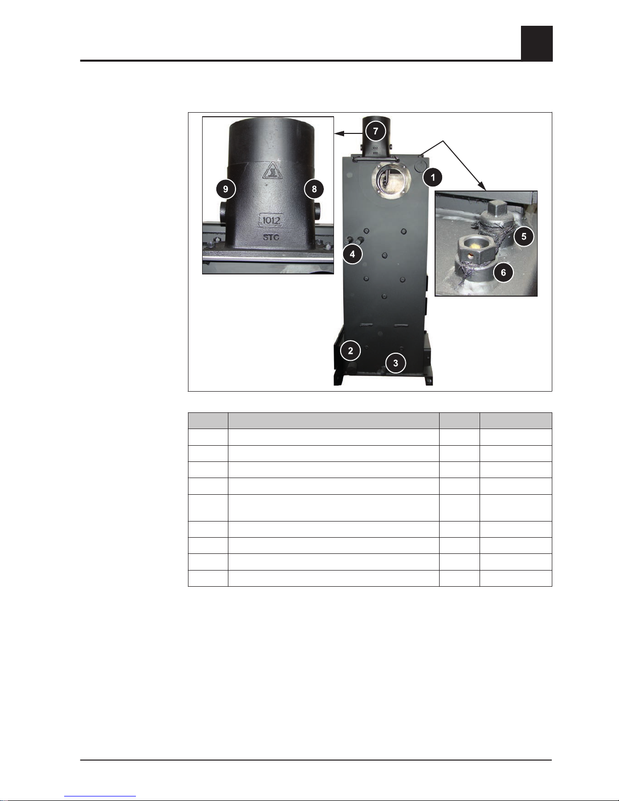
3.2 Components and connections
Item Description Unit S3 Turbo
1 Boiler flow connection inches 6/4
2 Boiler return connection inches 6/4
3 Drainage connection inches 1/2
4 Safety battery connection inches 1/2
5 Immersion sleeve for thermal discharge valve (sup‐
plied by the customer)
inches 1/2
6 Immersion sleeve for boiler sensor and STL inches 1/2
7 Flue gas pipe connection mm 150
8 Flue gas temperature sensor connection inches 1/2
9 Broadband probe connection inches 3/4
Technology
3
Components and connections
Installation Instructions S3 Turbo | M1080813_en 15

3.3 Technical specifications
Description S3 Turbo 18 S3 Turbo 28
Nominal output kW 22.5 31
Electrical connection 230V / 50Hz / fused C13A
Power consumption at nominal load W 70 50 - 70
Power consumption in slumber mode 3 3
Weight of boiler incl. insulation and control kg 525 535
Total boiler capacity (water) L 120 120
Water pressure drop (ΔT = 10 / 20 K) mbar 4.6 / 1.9 9.5 / 3.2
Minimum boiler return temperature °C 60
Maximum permitted operating temperature 90
Permitted operating pressure bar 3
Airborne sound level dB(A) < 70
Permitted fuel as per EN 14961 Part 5: Firewood class A2 / D15 L50
Fuel loading door dimensions (width / height) mm 330 / 370 330 / 370
Fuel loading chamber capacity L 140 140
Combustion time 1) - Beech
h 4.3 - 6.3 3.9 - 5.6
Combustion time1) - Spruce
3.0 - 4.4 2.8 - 3.9
1.Values specified for combustion time are guideline values at nominal load and will vary depending on water content (15-25%) and fill level
(80-100%).
Description S3 Turbo 36 S3 Turbo 45
Nominal output / range kW 36 / 18 - 36 45 / 22.5 – 45
Electrical connection 230V / 50Hz / fused C13A
Power consumption at nominal load W 45 – 75 65 - 75
Power consumption in slumber mode 3 3
Weight of boiler incl. insulation and control kg 610 620
Total boiler capacity (water) L 190 190
Water pressure drop (ΔT = 10 / 20 K) mbar 7.0 / 2.1 22.0 / 6.3
Minimum boiler return temperature °C 60
Maximum permitted operating temperature 90
Permitted operating pressure bar 3
Airborne sound level dB(A) < 70
Permitted fuel as per EN 14961 Part 5: Firewood class A2 / D15 L50
Fuel loading door dimensions (width / height) mm 330 / 370 330 / 370
Fuel loading chamber capacity L 210 210
Combustion time 1) - Beech
h 4.6 - 6.7 3.9 - 5.6
Combustion time1) - Spruce
3.2 - 4.7 2.7 - 4.0
1.Values specified for combustion time are guideline values at nominal load and will vary depending on water content (15-25%) and fill level
(80-100%).
3
Technology
Technical specifications
16 Froeling GesmbH | A-4710 Grieskirchen, Industriestraße 12 | www.froeling.at

Description S3 Turbo 18 S3 Turbo 28
Testing institute
TÜV Austria
1)
TÜV Austria
1)
Test report no.
11-U-407/SD
2)
11-U-407/SD
2)
Date of issue 22/07/2011 22/07/2011
Boiler class as per EN 303-5:2012 5 5
Boiler efficiency % 91.1 92.3
1.TÜV Austria Services GmbH, Geschäftsbereich Umweltschutz, Am Thalbach 15, A-4600 Thalheim/Wels
2.
As per ÖNORM / DIN EN 303-5, Section 5.1.3 type test: For a boiler from a range with a consistent nominal output from the largest to the
smallest boiler ≤ 2 : 1, to carry out the tests with the smallest and the largest boilers. The boiler manufacturer must ensure that all boilers
fulfil the requirements of the norm, including those in a specific range that have not been tested, which have values that have been deter‐
mined depending on nominal output by interpolation.
Test data - Emissions in [mg/MJ]1) (nominal load)
Carbon monoxide (CO) mg/MJ 90 58
Nitrogen oxide (NOx) mg/MJ 91 83
Organic hydrocarbons (OGC) mg/MJ 6 3
Dust mg/MJ 7 7
1.The pollutant concentration is specified as a mass based on the energy content of the fuel fed to the combustion system in mg/MJ
Test data - Emissions in [mg/m³]1) (nominal load)
Carbon monoxide (CO) mg/m³ 133 86
Nitrogen oxide (NOx) mg/m³ 134 123
Organic hydrocarbons (OGC) mg/m³ 10 5
Dust mg/m³ 11 10
1.Emissions values based on dry flue gas at standard temperature and pressure (0°C, 1013 mbar) with a volume content of oxygen of 13%
Description S3 Turbo 36 S3 Turbo 45
Testing institute
TÜV Austria
1)
TÜV Austria
1)
Test report no. 11-UW/Wels-
EX-128/4
2)
11-UW/Wels-
EX-128/5
Date of issue 21/07/2011 07/11/2011
Boiler class as per EN 303-5:2012 4 5
Boiler efficiency (nominal load / partial
load)
% 93.0 / 92.5 94.1 / 92.7
1.TÜV Austria Services GmbH, Geschäftsbereich Umweltschutz, Am Thalbach 15, A-4600 Thalheim/Wels
2.
The emissions values for the partial load are determined in accordance with the test drawing 10-U-665/SD of 16/12/2010 as indicated in
point 1.6 (a) and point 6 in the test report no. 11-UW/Wels-EX-128/4 of 21/07/2011.
Test data - Emissions in [mg/MJ]1) (nominal load/partial load)
Carbon monoxide (CO) mg/MJ 39 / 380 55 / 190
Nitrogen oxide (NOx) mg/MJ 79 / 76 85 / 86
Organic hydrocarbons (OGC) mg/MJ 1 / 15 2 / 7
Dust mg/MJ 7 / 9 9 / 10
1.The pollutant concentration is specified as a mass based on the energy content of the fuel fed to the combustion system in mg/MJ
Test data - Emissions in [mg/m³]1) (nominal load)
Carbon monoxide (CO) mg/m³ 58 / 559 81 / 280
Nitrogen oxide (NOx) mg/m³ 116 / 111 125 / 127
Organic hydrocarbons (OGC) mg/m³ 2 / 23 3 / 11
Test report data
S3 Turbo 18 - 28
Test report data
S3 Turbo 36 - 45
Technology
3
Technical specifications
Installation Instructions S3 Turbo | M1080813_en 17

Test data - Emissions in [mg/m³]1) (nominal load)
Dust mg/m³ 10 / 14 14 / 15
1.Emissions values based on dry flue gas at standard temperature and pressure (0°C, 1013 mbar) with a volume content of oxygen of 13%
3
Technology
Technical specifications
18 Froeling GesmbH | A-4710 Grieskirchen, Industriestraße 12 | www.froeling.at

4 Assembly
4.1 Materials supplied
The boiler comes on a pallet together with insulation, controller and accessories.
Some of the components come in cardboard packaging.
1 Boiler 5 Flue gas pipe nozzle
2 Insulation 6 Ceramic fibre seal
3 Controller 7 Induced draught fan
4 WOS system (heat exchanger
optimization system)
8 Cardboard box containing small parts
9 Pneumatic rods
10 Ash shovel
11 Cleaning kit
12 Cleaning brush, small
13 Cleaning brush, large
Not pictured: Installation and operating instructions, guarantee certificate, identification
plate
4.1.1 Tools required
The following tools are required for assembly:
❒
Spanner or box wrench set (widths across flats 8 – 32 mm)
❒ Allen key set
❒ Flat head and cross-head screwdrivers
❒ Hammer
❒ Diagonal cutting pliers
❒ Half-round file
❒ Power drill or cordless screwdriver with Torx bit insert
Assembly
4
Materials supplied
Installation Instructions S3 Turbo | M1080813_en 19
4.2 Positioning
NOTICE
Damage to components if handled incorrectly
❒
Follow the transport instructions on the packaging
❒ Transport components with care to avoid damage
❒ Protect the packaging against damp conditions
❒ Pay attention to the pallet's centre of gravity when lifting
❒
Position a fork-lift or similar lifting device at the pallet and bring in the components
If the boiler cannot be brought in on the pallet:
❒ Remove the cardboard and remove the boiler from the pallet
⇨ See "Remove boiler from pallet" [page 21]
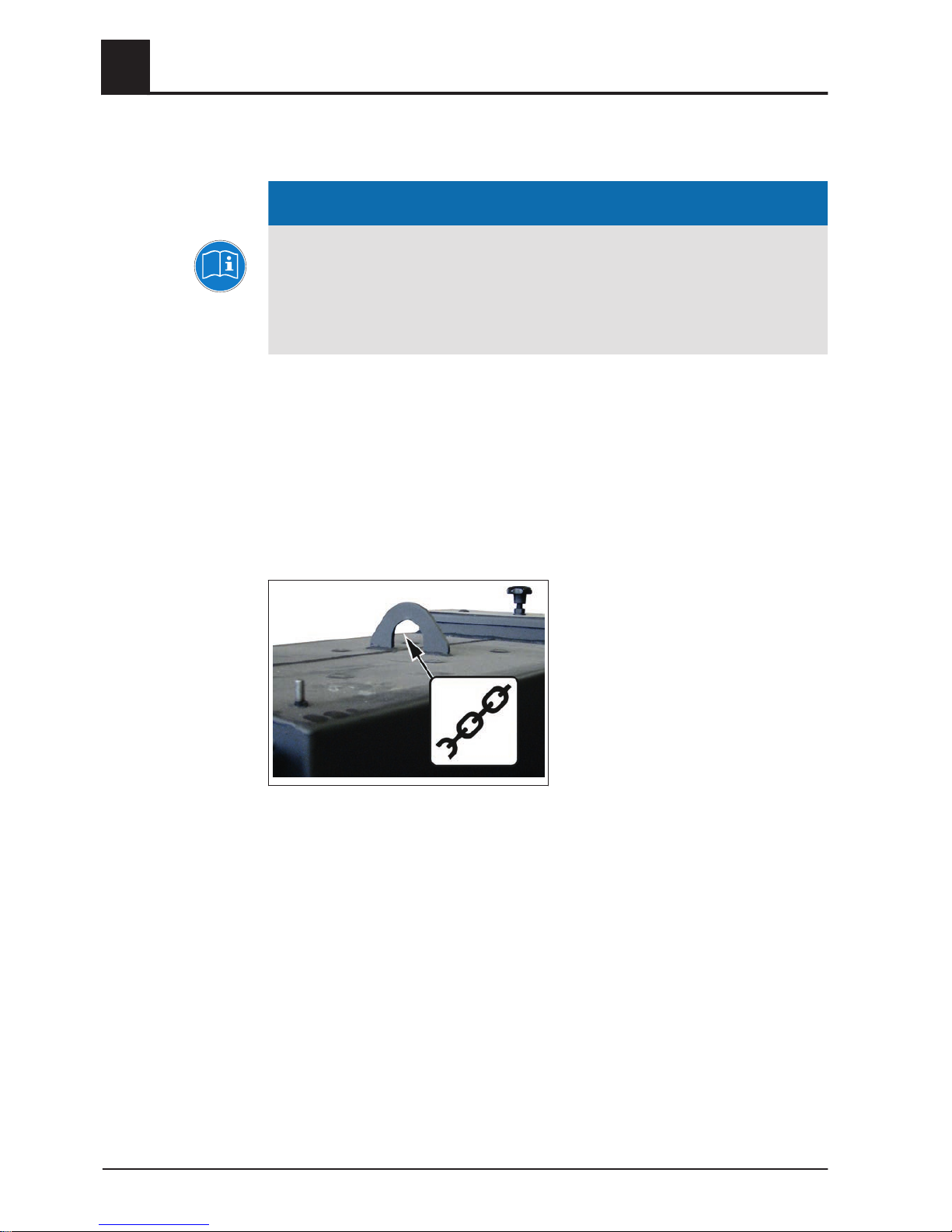
Positioning using a crane
❒ Attach the crane hook to the attachment point correctly and position the boiler
4.2.1 Temporary storage
If the system is to be assembled at a later stage:
❒
Store components at a protected location, which is dry and free from dust
➥ Damp conditions and frost can damage components, particularly electric ones!
4
Assembly
Positioning
20 Froeling GesmbH | A-4710 Grieskirchen, Industriestraße 12 | www.froeling.at
4.3 Setting up in the boiler room
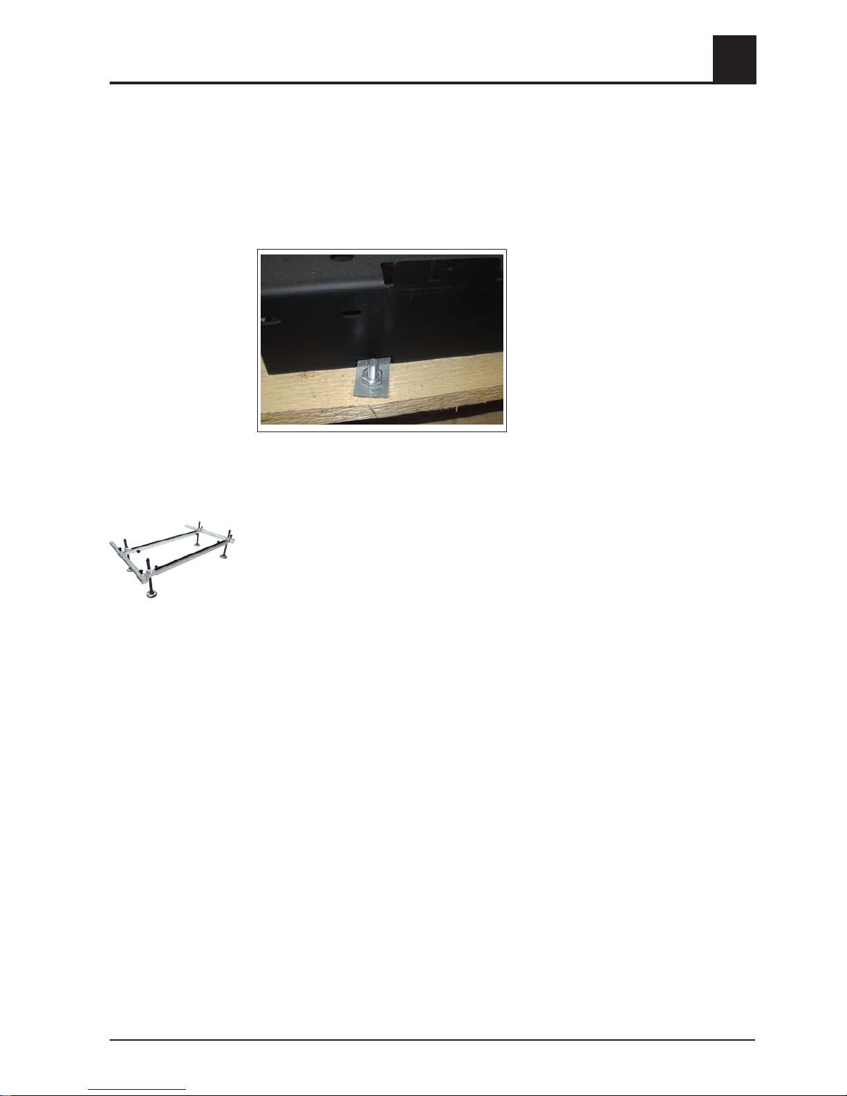
4.3.1 Remove boiler from pallet
❒ Remove the cardboard with the controller from the boiler and put in a safe place
❒
Lift the cardboard box with the insulation from the pallet
❒ Remove the transport locks
➥ A total of four screws, left/right, front/rear
❒
Lift boiler from pallet
TIP: Use Froling’s KHV 1400 boiler lifting system to help remove the pallet!
4.3.2 Moving the boiler in the boiler room
❒ Position a fork-lift or similar lifting device with a suitable load-bearing capacity at
the base frame
❒
Lift and transport to the intended position in the installation room
➥ Observe the minimum distances in the boiler room.
Assembly
4
Setting up in the boiler room
Installation Instructions S3 Turbo | M1080813_en 21

4.3.3 Minimum distances in the boiler room
▪ The system should generally be set up so that it is accessible from all sides allow‐
ing quick and easy maintenance.
▪
Regional regulations regarding necessary maintenance areas for inspecting the
chimney should be observed in addition to the specified minimum distances!
▪ Observe the applicable standards and regulations when setting up the system.
▪ Observe additional standards for noise protection
(ÖNORM H 5190 - Noise protection measures)
Dimen‐
sion
Description Unit S3 Turbo
A Distance - front of boiler to wall mm 800
B Distance – side of boiler to wall
800 (200)
1)
C Distance – back to wall 500
D Distance – side of boiler to wall
200 (800)
1)
1.The side of the boiler where the WOS lever is located (B or D) should be at least 800 mm from the wall to allow easy access for connecting
the appliance and for maintenance work (e.g. induced draught).
4.4 Before Installation
4.4.1 Changing door stops (as needed)
The boiler comes with the door stop on the right. To change the side the door stops
are on, proceed as follows.
Changing the stop of the combustion chamber door
The following example shows how to change the door stop on the combustion cham‐
ber door. The procedure is the same for changing the stop on the fuel loading door
and pre-heating chamber door!
❒ Open the combustion chamber door
4
Assembly
Setting up in the boiler room
22 Froeling GesmbH | A-4710 Grieskirchen, Industriestraße 12 | www.froeling.at

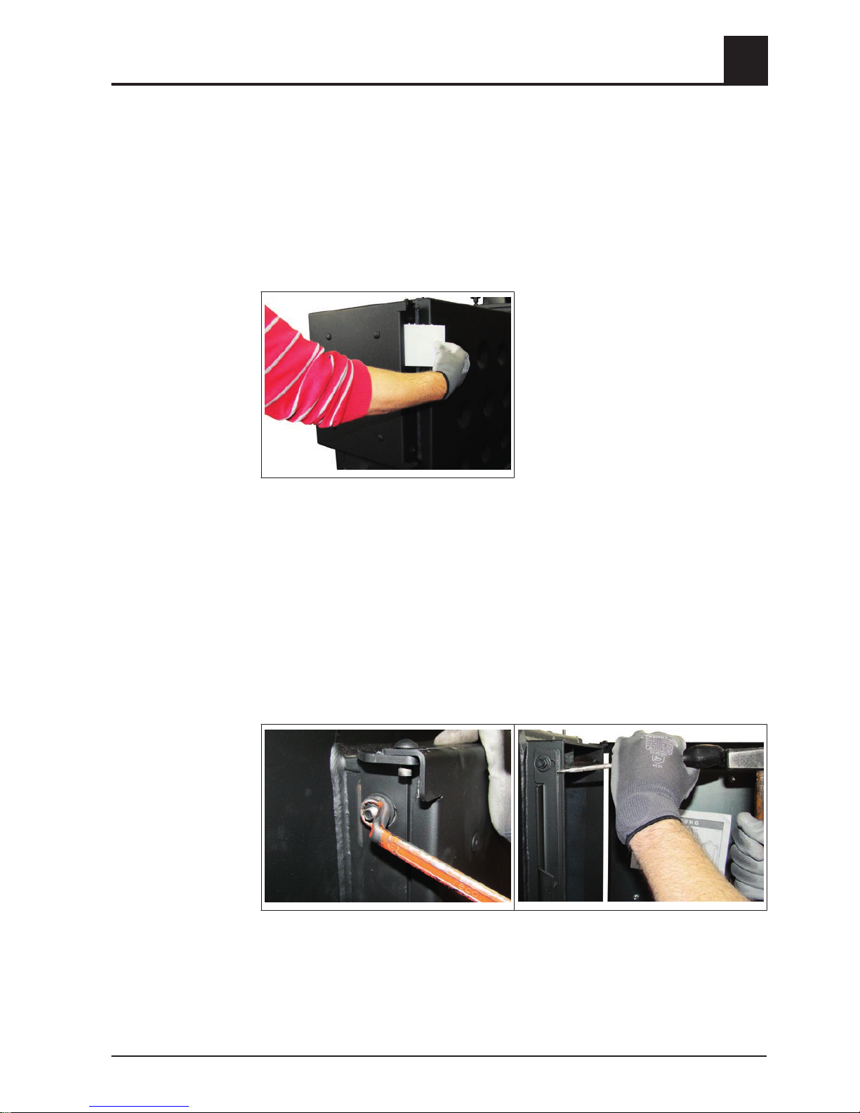
❒ Undo the retainer of the hinge pin at the top and bottom door hinge
➥ You can use two screwdrivers to gently bend the retainer plate out to loosen it
❒
Take out the top and bottom hinge pins and remove the combustion chamber door
❒ Remove the locking plate and hinge
➥ Loosen the nuts (M8) with Allen wrench (13 mm)
❒
Remount the locking plate and hinge with spacer washers and nuts on the other
side
➥ Only partially tighten the nuts
NOTICE! When changing the stop of the fuel loading door, at this point, the fuel load‐
ing door must be converted. ⇨ See "Converting the fuel loading door" [page 24]
❒ Rotate the door and rehang it with the stop on the other side
➥ Secure at the top and bottom with the hinge pins
❒
Refit the retainers to the top and bottom hinge pins
➥ To do so, you can use two screwdrivers
Assembly
4
Before Installation
Installation Instructions S3 Turbo | M1080813_en 23

❒ Use suitable tools (e.g. screwdriver and hammer) to push the hinge far enough to‐
ward the rear so that when the door is closed, there is slight resistance at a gap of
approx. 2-3 cm
➥ Caution: the hinge must be aligned in the same way at the top and bottom!
❒ Tighten the nuts at the top and the bottom on the side of the door with the stop
NOTICE! When the door stops have been changed, you must check the settings and
seal of the door.
⇨ See "Setting and checking the seal on the doors" [page
26]
Converting the fuel loading door
❒ Remove the radiation plate together with the seal
4
Assembly
Before Installation
24 Froeling GesmbH | A-4710 Grieskirchen, Industriestraße 12 | www.froeling.at

❒ Carefully lift out the insulating plate
❒
Turn the insulating plate by 180° and position it so that it lines up with the holes
provided
❒ Re-install the radiation plate
❒
Use contact adhesive to fix the seal in place
4.4.2 Fitting the door handles
The example below shows how to mount the fuel loading door handles. The procedure
is the same for mounting the handles of the combustion chamber door and the preheating chamber door!
❒ Position the door handle in the hole provided
❒
Insert flange bushing into door handle and secure it
Assembly
4
Before Installation
Installation Instructions S3 Turbo | M1080813_en 25

4.4.3 Setting and checking the seal on the doors
The example below shows how to set and check the seals on the fuel loading doors.
The procedure is the same for the combustion chamber door and the pre-heating
chamber door!
On the side with the door stop
❒ Close the door
➥ Slight resistance at a gap of 2 - 3 cm:
Setting okay
➥ No resistance or very slight resistance:
Setting must be corrected - push the hinge toward the back
⇨ See "Positioning the doors" [page
27]
➥ Resistance at a gap of >3 cm:
Setting must be corrected - push the hinge toward the front
⇨ See "Positioning the doors" [page 27]
❒ Open the door
❒
Insert a sheet of paper at both the top and the bottom area of the door stop be‐
tween the door and the boiler
❒ Close the door
❒ Try to pull the sheet of paper out
➥ If the paper cannot be removed:
the door seal is OK!
➥ If the paper can be removed:
the door is not sealed properly - push the hinge toward the back!
⇨ See "Positioning the doors" [page 27]
Checking the setting:
Checking the seal:
4
Assembly
Before Installation
26 Froeling GesmbH | A-4710 Grieskirchen, Industriestraße 12 | www.froeling.at
On the side with the door handle
❒ Close the door
➥ If the door can be opened with the usual force:
Setting okay
➥ If the door cannot be opened with the usual force or must be forced open
:push the locking plate toward the front
⇨ See "Positioning the doors" [page
27]
❒ Open the door
❒
Insert a sheet of paper at both the top and the bottom area at the side of the door
handle between the door and the boiler
❒ Close the door
❒ Try to pull the sheet of paper out
➥ If the paper cannot be removed:
the door seal is OK!
➥ If the paper can be removed:
the door is not sealed properly - push the locking plate toward the back!
⇨ See "Positioning the doors" [page 27]
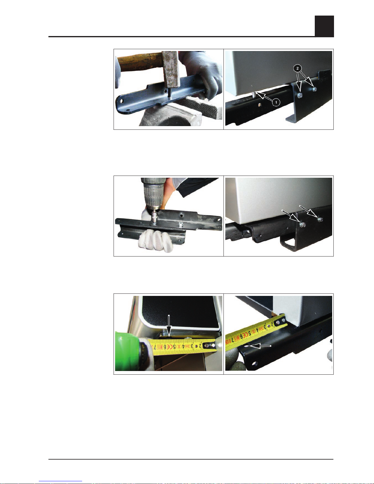
Positioning the doors
❒ Using an Allen key (13 mm), loosen the nuts on the locking plate and/or hinge at
the top and bottom
❒
Use suitable tools (e.g. screwdriver and hammer) to move the locking plate and/or
hinge to the rear or the front as needed
➥ Caution: The locking plate and/or hinge must be aligned in the same way at the
top and bottom!
❒ Tighten the nuts at the top and bottom
Checking the setting:
Checking the seal:
Assembly
4
Before Installation
Installation Instructions S3 Turbo | M1080813_en 27

4.5 Installing the boiler
4.5.1 Assembly overview
Insulation
6
7
5
2
3
2
3
6
7
8
9
11
10
12
13
14
16
17
18
19
22
20
23
3
24
28
29
26
27
1
4
4
25
16
32
30
30
31
31
21
A
Detail A
36
37
33
34
22
21
35
15
31
41
41
40
38
39
4
4
S3 Turbo 18/28:
4
Assembly
Installing the boiler
28 Froeling GesmbH | A-4710 Grieskirchen, Industriestraße 12 | www.froeling.at

Item Quan‐
tity
[units]
Description Item Quan‐
tity
[units]
Description
1 1 Insulated door, complete 2 2 Magnetic latches
3 3 Grip recess 4 2 Flange bushing (8x6x12x8)
5 1 Sticker, FROELING S3 TURBO 6 1 U-plate – S3 Turbo 36/45
fitting grooved pin (6x30) – S3 Turbo 18/28
7 1 Lower door bracket 8 1 Lower spacer plate
9 1 Complete floor insulation 10 1 Insulation mounting brackets, left
11 1 Insulation cover plate, left 12 1 Cover plate
13 1 Insulating side panel, left, complete 14 1 Thermal insulation, rear
15 1 Back panel, complete 16 2 Cover plate for ID fan
17 1 Heat insulation mat, top/rear 18 1 Heat insulation mat, top
19 1 Heat insulation mat, top/front 20 1 Controller cover
21 2 Contact washer M4 22 2 Hexagonal screw M6 x 100
23 1 Insulating cover, back 24 1 Upper spacer plate
25 1 Hinge pin, insulated door 26 1 Insulation mounting brackets, right
27 1 Insulation cover plate, right 28 1 Insulating side panel, right, complete
33 1 Sticker, "Primary air actuator"
(only with S-Tronic Lambda)
34 1 Sticker, "Secondary air actuator"
(only with S-Tronic Lambda)
35 1 Torque support, servo-motor
(only with S-Tronic Lambda)
36 2 Counter plate for magnetic latches
37 2 Thread forming screw M3x10
Assembly
4
Installing the boiler
Installation Instructions S3 Turbo | M1080813_en 29
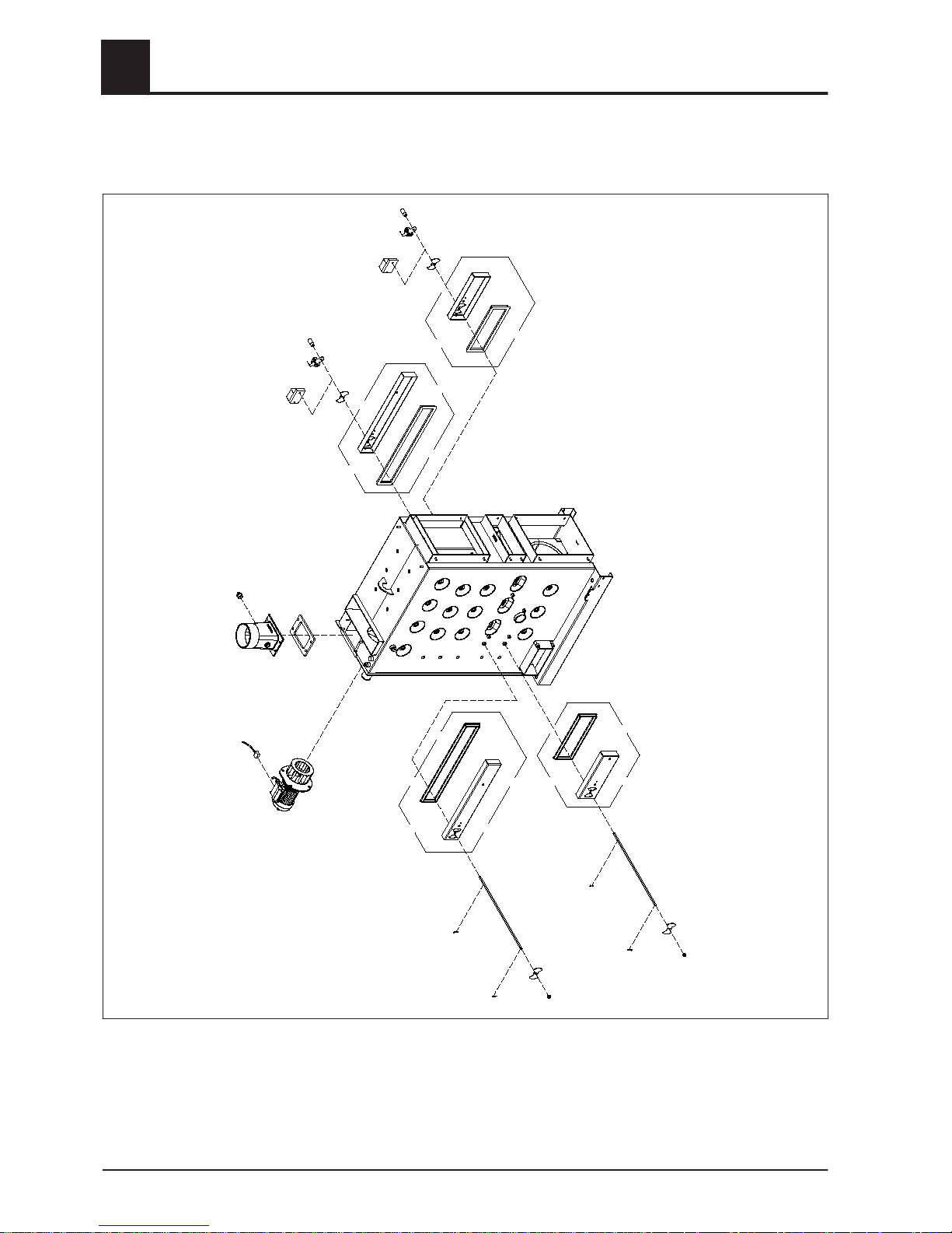
Air duct system
3
4
5
6
7
8
9
11
12
8
6
7
11
12
13
13
8
8
14
14
14
15
15
1
22
21
22
10
9
10
4
Assembly
Installing the boiler
30 Froeling GesmbH | A-4710 Grieskirchen, Industriestraße 12 | www.froeling.at

Item Quan‐
tity
[units]
Description
1 1 Induced draught fan 2800U, complete, with rotation speed transducer
3 1 Ceramic fibre seal 210x144x12
4 1 Flue gas pipe nozzle ø150
5 1 Blanking plug 3/4"
6 2 Air duct, primary air, left and right
7 2 Rubber seal for profile 12x2x15x23, L=1600
8 4 Air flap
9 2 Manual controller for air control system (S-Tronic/S-Tronic Plus)
10 2 Handle, black
11 2 Air duct, secondary air, left and right
12 2 Rubber seal for profile 12x2x15x23, L=1000
13 2 Pneumatic rods
14 4 Split pin ø3.2x20
15 2 Pressure spring ø17.8x1.1x28
21 1 Induced draught cable incl. rotation speed transducer cable - 2m
22 2 Servo-motor LM 24AP5-F/300.1 (S-Tronic Lambda)
Assembly
4
Installing the boiler
Installation Instructions S3 Turbo | M1080813_en 31

WOS system S3 Turbo 18-28
1
2
3
4
6
7
7
8
9
9
8
10
11
12
13
5
4
Assembly
Installing the boiler
32 Froeling GesmbH | A-4710 Grieskirchen, Industriestraße 12 | www.froeling.at

Item Quan‐
tity
[units]
Description
1 1 WOS lever, complete
2 1 Handle
3 1 Brass bushing SW27x20
4 4 WOS turbulator ø50x6x3x837
5 1 WOS bracket, complete 6x3
6 1 Linking plate for turbulator 6x3
7 2 Bolt ø8x16
8 2 Spacer washer M8
9 2 Split pin ø2x16
10 1 Stay tube WOS
11 1 Clamping jaw
12 1 Spacer tube ø21.3x50
13 1 Rosette ø77x15.5
Assembly
4
Installing the boiler
Installation Instructions S3 Turbo | M1080813_en 33
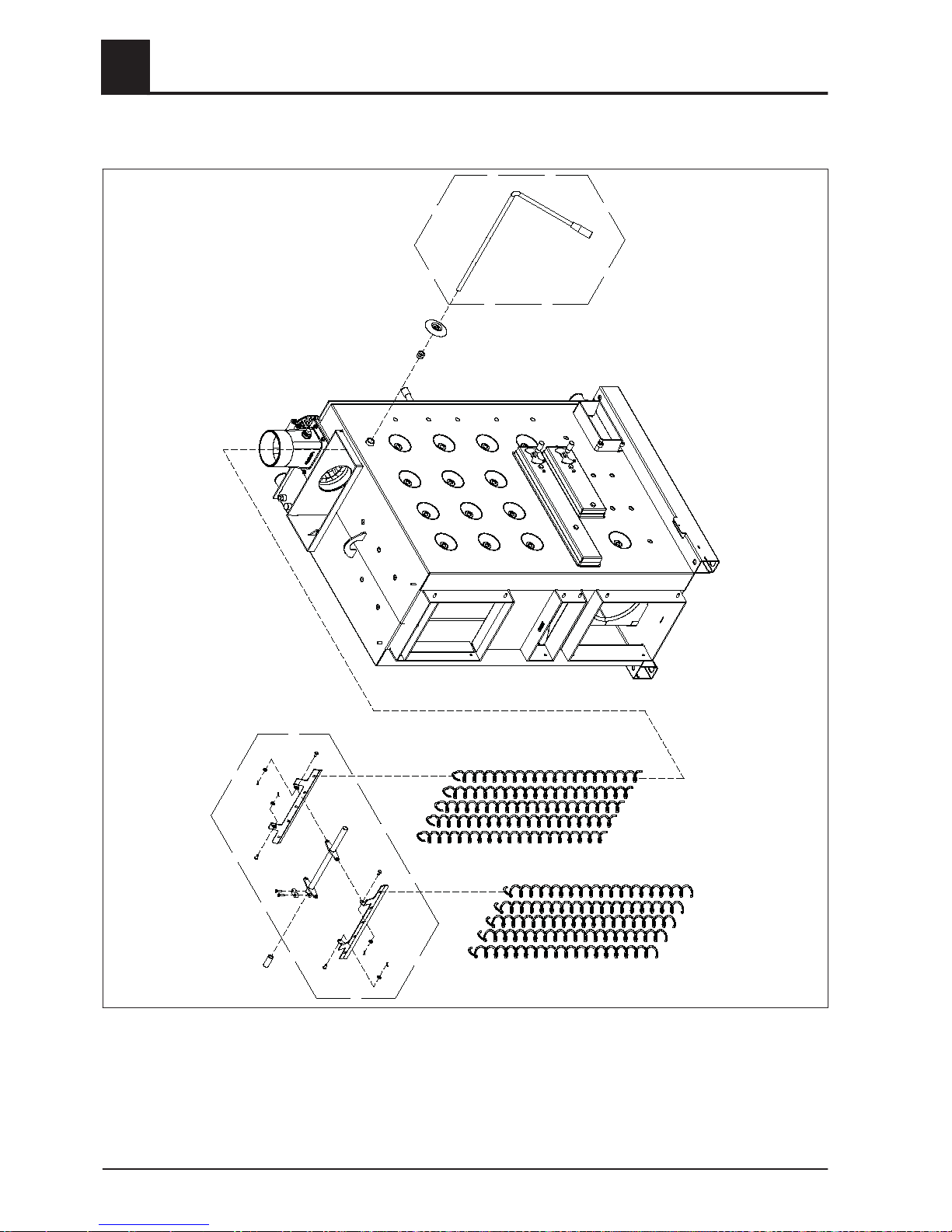
WOS system S3 Turbo 36-45
2
3
1
4
6
7
6
9
9
10
11
10
11
12
9
9
8
4
10
11
10
11
5
13
4
Assembly
Installing the boiler
34 Froeling GesmbH | A-4710 Grieskirchen, Industriestraße 12 | www.froeling.at

Item Quan‐
tity
[units]
Description
1 1 WOS lever, complete
2 1 Handle
3 1 Brass bushing SW27x20
4 10 WOS turbulator ø50x6x3x932
5 1 WOS bracket, complete 6x3
6 2 Linking plate for turbulator 6x3
7 1 Stay tube
8 1 Clamping jaw
9 4 Bolt ø8x16
10 4 Split pin ø2x16
11 4 Spacer washer M8
12 1 Spacer tube ø21.3x91
13 1 Rosette ø77x15.5
Assembly
4
Installing the boiler
Installation Instructions S3 Turbo | M1080813_en 35

4.5.2 Installing the flue gas pipe nozzle
❒ Place the ceramic fibre seal in position
❒
Position the flue gas pipe nozzle and attach it using the pre-installed spacer wash‐
ers and nuts
➥ Caution: ½" connection must point to the right as seen from behind!
4.5.3 Fit the induced draught fan
❒ Position the induced draught fan on the back of the boiler and mount it with the
four screws
➥ Caution: Do not overstress the flange!
4.5.4 Installing the pneumatic rods for the primary and secondary air
Manual controllers or servo-motors can be mounted on either the left or the right side
on the boiler
❒
Remove the split pin on both pneumatic rods opposite the spring and pull one of
the air flaps off of each
4
Assembly
Installing the boiler
36 Froeling GesmbH | A-4710 Grieskirchen, Industriestraße 12 | www.froeling.at

❒ Loosen the two screws at the lower and upper air duct on the right side of the boil‐
er
❒
Screw in the screws at the lower and upper air duct on the left side of the boiler far
enough to allow the air flap to make contact with the thread
❒ Loosen the screws at the lower and upper air duct on the right side of the boiler far
enough to allow the air flap to make contact with the thread
The following procedures are used to mount the pneumatic rod if the manual control‐
lers/servo-motors are mounted on the left side of the boiler. If the manual controllers/
servo-motors are mounted on the right side of the boiler, complete the following proce‐
dures with the sides reversed accordingly.
❒ Insert both pneumatic rods at the right-hand side of the boiler
➥ The air flaps with springs lie flat on the right air ducts!
Manual controller/ser‐
vo-motor, left
Manual controller/ser‐
vo-motor, right
Assembly
4
Installing the boiler
Installation Instructions S3 Turbo | M1080813_en 37

❒ Insert the air flaps on the pneumatic rods on the left side and secure them with
split pins
➥ CAUTION: The air flaps must be situation in the same position as those on the
opposite side!
❒
Turn both pneumatic rods in an anti-clockwise direction as far as the stop
4.5.5 Final steps before insulating
❒ Seal and screw in the immersion sleeve for thermal discharge safety device sen‐
sor
❒ Detach blanking plate for the side cleaning port
❒ Remove the screw cap from the side on which the WOS lever will be mounted lat‐
er and replace it with a brass bushing
➥ Tighten the brass bushing with Allen wrench (27 mm)
❒
Seal the broadband probe connection with a 3/4" blanking plug (2)
➥ On the S3 Turbo with S-Tronic Lambda, the broadband probe will be mounted
here later
Only for S-Tronic
and S-Tronic Plus:
4
Assembly
Installing the boiler
38 Froeling GesmbH | A-4710 Grieskirchen, Industriestraße 12 | www.froeling.at
4.5.6 Installing the insulation
NOTICE
Separate parts of the boiler are fitted with a protective film. This MUST be re‐
moved before assemby!
❒ Push in the bottom insulation
❒ Inset the two L-shaped insulation cover plates at the insulating side panels at left
and right and secure them with three thread forming screws each
➥ Insert the cover plates such that the rivet (1) is at the bottom!
❒ Insert the insulation mounting brackets at both insulating side panels and secure
them with the two top thread forming screws (1)
➥ At the front, the bracket will be secured later when the upper spacer plate is
inserted!
Assembly
4
Installing the boiler
Installation Instructions S3 Turbo | M1080813_en 39

❒ Cut the perforated plates for the cleanout opening on both sides and bend them
inward
➥ Caution: bend the plates > 100° inward!
❒ Place one large spacer washer on each of the threaded bolts to the right and the
left above on the boiler
❒
Insert the insulating side panels at the base of the boiler at the flap and push them
onto the boiler
❒ Position the side panels with the door bracket onto the threaded bolts and secure
them lightly with a large and a small spacer washer and nut (1)
❒
Hang the upper spacer plate on the rivets between the insulating side panels and
attach with a thread forming screw (2)
➥ At the same time, this procedure also secures the bracket to the insulating side
panels at the front
4
Assembly
Installing the boiler
40 Froeling GesmbH | A-4710 Grieskirchen, Industriestraße 12 | www.froeling.at
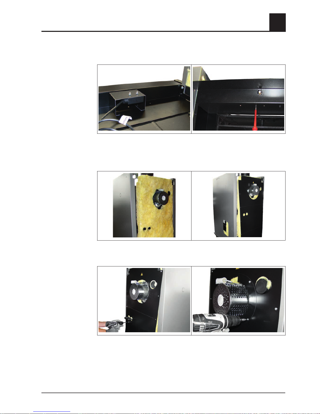
4.5.7 Installing the door switch
❒ Secure the bracket with pre-mounted door switch to the upper spacer plate with
two thread forming screws M4x8
4.5.8 Installing the back panel
❒ Position the rear thermal insulation on the rear side of the boiler
❒
Insert insulating back panel over induced draught fan
❒ Secure the insulating back panel to the left and right with nine thread forming
screws each
❒
Install the cover plates for ID fan
Assembly
4
Installing the boiler
Installation Instructions S3 Turbo | M1080813_en 41

4.5.9 Aligning the insulation and attaching the controller
❒ Hang the lower spacer plate on the rivets (1) between the insulating side panels
and attach with one thread forming screw (2) each
❒
Push the insulating side panels toward the rear until the borehole on the flaps cor‐
responds with the borehole on the side panels
❒ Secure the insulating side panels to the right and left at the flap on the boiler base
with thread forming screws
❒
Measure the diagonals and align the insulating side panels so that the two diago‐
nals are the same
➥ Adjust the position of the side panels if necessary
❒ Tighten the nuts on the two brackets of the insulating side panels at the top on the
boiler
❒
Position the control on top
4
Assembly
Installing the boiler
42 Froeling GesmbH | A-4710 Grieskirchen, Industriestraße 12 | www.froeling.at
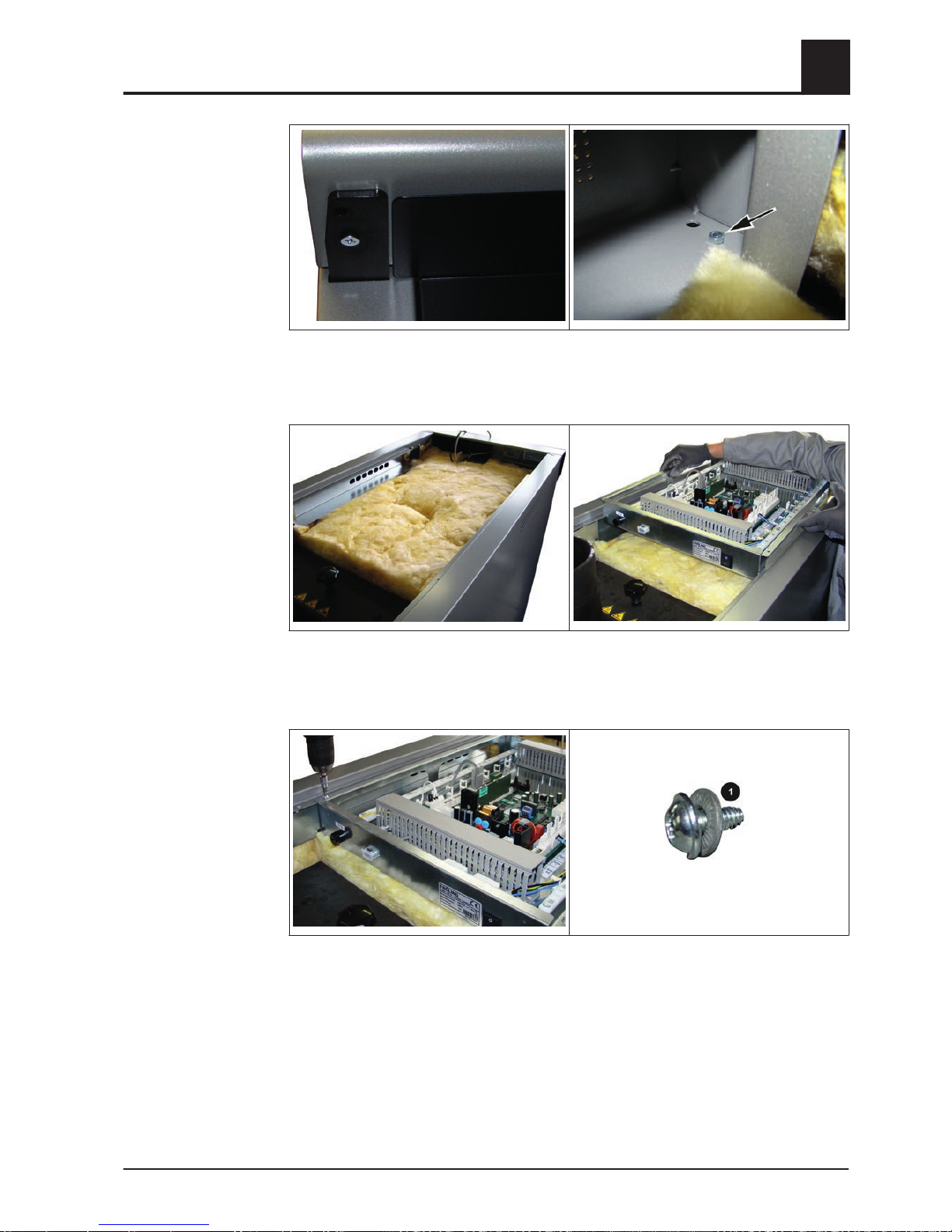
❒ Insert one countersunk cross-head screw each to the left and right through the
bracket and control from below
❒
Use nuts to secure the countersunk cross-head screws from the top.
❒ Put the top heat insulation mat on
➥ The heat insulation mat must touch the front sheet
❒
Place the controller box on the boiler
❒ Use eight thread forming screws incl. contact washers (1) to install controller box
on the cable duct of the side panels
Assembly
4
Installing the boiler
Installation Instructions S3 Turbo | M1080813_en 43

❒ Screw in two carrying bolts (hexagonal bolts M6x100) to the left and right at the
bottom rear side of the controller far enough to ensure that the controller and insu‐
lation are supported adequately
4.5.10 Installing the cleaning port door and blank cover
NOTICE! Recommendation for easier maintenance: mount the cleaning port door on
the same side as the WOS lever!
❒ Use three Allen screws to mount the cleaning port door on the desired side
➥ Start with the screws at upper right!
❒
Attach the door handle for the cleaning port door using a round headed screw
❒ Install the blank cover for the side cleaning port on the opposite side
4.5.11 Installing the insulated door
The illustrations show the assembly for the door stop on the right. If the insulated door
is attached on the left, complete the following procedures with the sides reversed ac‐
cordingly.
4
Assembly
Installing the boiler
44 Froeling GesmbH | A-4710 Grieskirchen, Industriestraße 12 | www.froeling.at
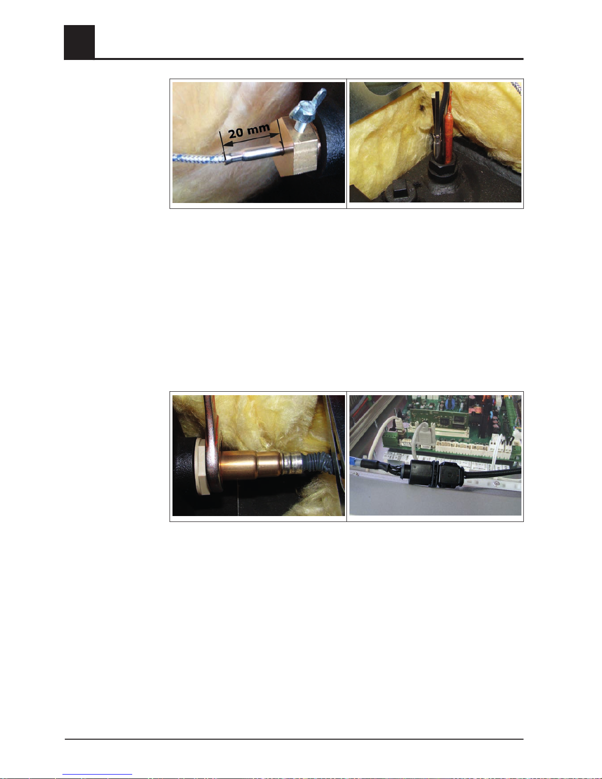
❒ Tap in a fitting grooved pin at the lower door bracket
❒
Slide the lower door bracket into the base of the boiler
➥ Insert the fitting grooved pin (1) into the insulation
➥ Lightly tighten the two hexagonal screws M6x12 (2)
❒ Mount the lower door bracket with two hexagonal screws M6x12 on the U-profile
❒
Insert the door bracket with the U-profile and lightly tighten the two hexagonal
screws M6x12
❒ Measure the distance from the insulating side panel to the centre of the borehole
for the insulated door on the upper bracket
❒
Measure the distance from the insulating side panel to the centre of the borehole
on the lower door bracket
➥ The two distances must be equal!
➥ If necessary, correct the position of the lower door bracket
S3 Turbo 18/28:
S3 Turbo 36/45:
Assembly
4
Installing the boiler
Installation Instructions S3 Turbo | M1080813_en 45

❒ Secure the lower door bracket
❒
At the front end of the lower door bracket, insert a hexagonal screw M6x30 from
below, secure it with a nut and place a spacer washer on top
❒ Insert flange bushings at the top and the bottom on the side of the insulated door
with the stop
❒
Mount the insulated door onto the lower door bracket using the hexagonal screw
❒ Attach the insulated door to the upper door bracket with hinge pin (1)
➥ Insert the hinge pin through the control and the upper door bracket
4
Assembly
Installing the boiler
46 Froeling GesmbH | A-4710 Grieskirchen, Industriestraße 12 | www.froeling.at

❒ Position magnetic latches on the inside of the insulated door at the top and bottom
❒
Mount counter plates for the magnetic latches to the left insulation side panel
❒ Check to see if the gap between the insulation side panel and the insulated door is
the same size along the entire height of the boiler
➥ If necessary, correct the position of the lower door bracket
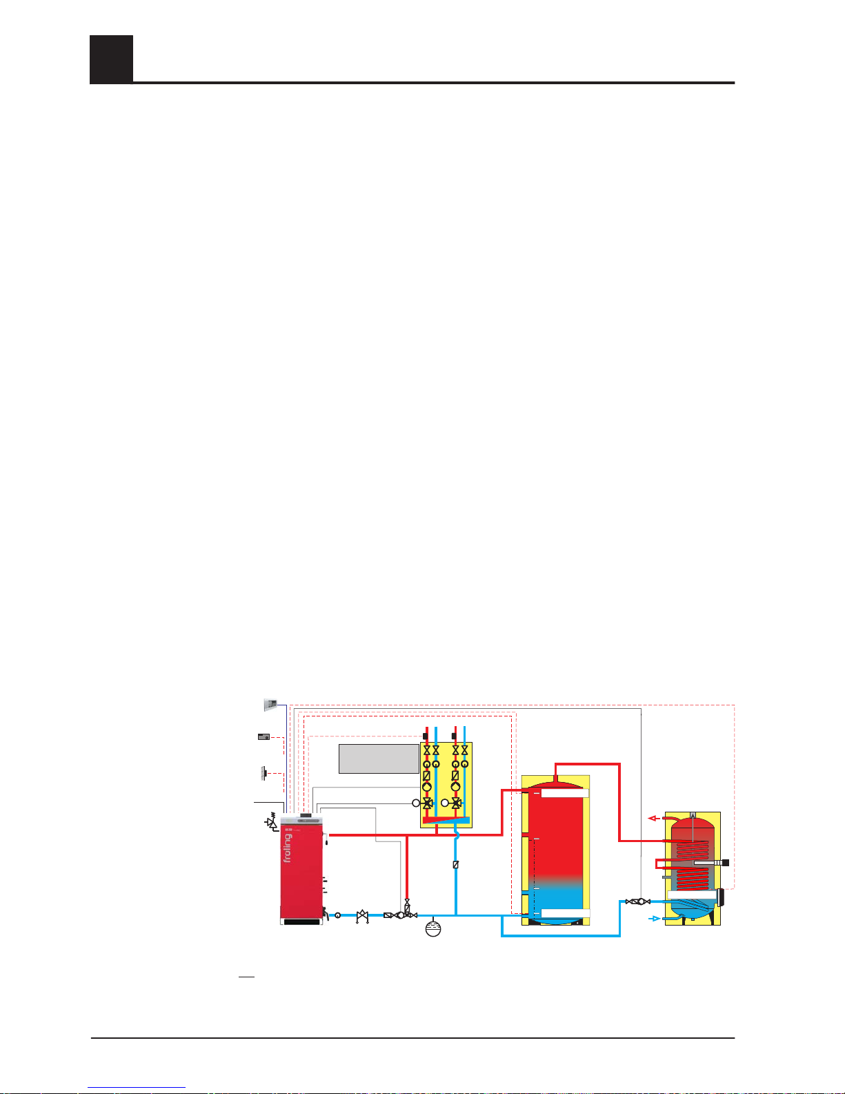
4.5.12 Fitting the sensors
❒ Screw in the brass bushing for the flue gas temperature sensor
➥ Make sure that the borehole with the thread is situated at the upper area of the
brass bushing
Assembly
4
Installing the boiler
Installation Instructions S3 Turbo | M1080813_en 47
❒ Push the flue gas temperature sensor in so that it protrudes approx. 20 mm from
the housing and secure the position with the wing screw
❒
Push the boiler sensor and STL capillary into the pre-installed immersion sleeve
with the pressure spring during boiler outfeed
❒ Run the cable through the cable duct to the controller box
➥ Tuck any extra cable into the cable duct
4.5.13 Install the broadband probe (only with S-Tronic Lambda)
❒
Unscrew the pre-installed bushing from the broadband probe
❒ Screw the bushing into the flue gas nozzle and gently tighten
❒ Screw the broadband probe into the bushing and gently tighten using an Allen
wrench (22 mm)
❒
Plug in the extension cable for the Lambda probe and un the cable through the ca‐
ble duct to the controller box
➥ Tuck any extra cable into the cable duct
4
Assembly
Installing the boiler
48 Froeling GesmbH | A-4710 Grieskirchen, Industriestraße 12 | www.froeling.at

4.5.14 Installing the WOS system
❒ Remove the pre-punched blanking in the insulation side panel on the same side
as the brass bushing
➥ File rough edges using a half-round file and remove burrs
❒
Slide the plastic cover onto the WOS lever
S3 Turbo 18/28:
S3 Turbo 36/45:
❒ Remove the heat exchanger cover
❒ Hang the WOS turbulators on the linking plate of the stay tube
➥ Make sure that you fit the turbulators in the right direction:
➥ Hold the linking plate with the edge toward the top
➥ Hang the WOS turbulators over the edge
Assembly
4
Installing the boiler
Installation Instructions S3 Turbo | M1080813_en 49

❒ Position the WOS turbulators at the heat exchanger pipes
❒ Position the WOS turbulators at the heat exchanger pipes
❒ Position the spacer tube at the stay tube
❒
Push the WOS lever through the distance and stay tubes from the outside and se‐
cure it at the stay tube with a clamping jaw
S3 Turbo 18/28:
S3 Turbo 36/45:
4
Assembly
Installing the boiler
50 Froeling GesmbH | A-4710 Grieskirchen, Industriestraße 12 | www.froeling.at

S3 Turbo 18/28: S3 Turbo 36/45:
❒ Place the heat exchanger cover on top
❒
Turn the handle of the heat exchanger cover to the right
❒ Tighten the nut below the handle
4.5.15 Installing the manual controller/servo-motors
❒ Use thread forming screws to secure the cover plate on the manual controller/ser‐
vo-motor side
➥ Check to see if the air flaps are at the left stop
Mounting the manual controller (with S-Tronic/S-Tronic Plus control)
❒ Place the air flap manual controllers on the pneumatic rod so that the manual con‐
troller is at the left stop and secure them with one thread forming screw each
❒
Place the handle onto the pneumatic rod
Assembly
4
Installing the boiler
Installation Instructions S3 Turbo | M1080813_en 51

❒ Check to see if the air flaps can be opened to the right
➥ The exact position of the manual controller is set on initial start-up
⇨ See "Boiler with manual controller" [page
65]
❒ Use thread forming screws to secure the cover plate on the opposite side
Mounting the servo-motors (with S-Tronic Lambda control)
❒ Check to see if the air flaps are at the left stop
➥ All air flaps are closed
❒ Set the servo-motors:
➥ Set the direction of rotation of the servo-motor (1) to left (L)
➥ Press the unlock key (2) and turn the drive for the shaft to the air duct (3) in an
anti-clockwise direction as far as the stop
❒
Place the servo-motors onto the pneumatic rod
❒ Position the torque support and partially tighten the screws
❒
Align the servo-motors so that they are straight and tighten the screws
4
Assembly
Installing the boiler
52 Froeling GesmbH | A-4710 Grieskirchen, Industriestraße 12 | www.froeling.at

❒ Use thread forming screws to secure the cover plate on the opposite side
❒ Attach the sticker at the end of the servo-motor cable
➥ Primary air: top servo-motor
➥ Secondary air: bottom servo-motor
❒
Push in the pre-punched opening for the cable duct onto the insulation
❒ Run the cable from the two servo-motors through the cable duct upward to the
controller
Assembly
4
Installing the boiler
Installation Instructions S3 Turbo | M1080813_en 53

4.6 Power connection and wiring
DANGER
When working on electrical components:
Risk of electrocution!
When work is carried out on electrical components:
❒ Only have work carried out by a qualified electrician
❒ Observe the applicable standards and regulations
➥ Work must not be carried out on electrical components by unauthorised
persons
4.6.1 S-Tronic control
Power connection
Core module S-Tronic
4
Assembly
Power connection and wiring
54 Froeling GesmbH | A-4710 Grieskirchen, Industriestraße 12 | www.froeling.at

Connection instructions
Port Cable dimensions / Specifications / Information
Bus (1) Port with cable – LIYCY paired 2x2x0.5;
Connecting the bus cable
❒
Warning! CAN L and CAN H must not be connected to +U
BUS
!
Bus (2) Patch cable CAT 5 RJ45 SFTP 1:1 configuration
Bus (3) Patch cable CAT 5 RJ45 SFTP 1:1 configuration, boiler display
port
COM 2 (4) Null modem cable 9-pin SUB-D
COM 1 (5) Null modem cable 9-pin SUB-D
Service interface for installing new boiler software or port for the
visualisation software
STL (6)
Connection cable1) 2 x 0.75mm
2
EMERGENCY STOP (7)
Connection cable1) 2 x 0.75mm
2
❒
Warning! Do not connect the emergency off/emergency stop
switch to the power supply cable of the boiler. The switch
must be a N/C switch and it must be linked to the 24V safety
chain of the STL at this terminal.
Outside temperature sen‐
sor (8)
Connection cable1) 2 x 0.75mm2, shielded from 25m cable length
Door switch TCS (9)
Connection cable1) 2 x 0.75mm
2
Sensor (10 + 11)
Connection cable1) 2 x 0.75mm2, shielded from 25m cable length
Return sensor RTS (12)
Connection cable1) 2 x 0.75mm
2
Boiler sensor BS (13)
PWM / 0-10V pump 1 (14)
Induced draught (15)
Connection cable1) 5 x 1.5mm
2
Pump 1 on
core module (16)
Connection cable1) 3 x 1.5mm2, max. 1.5A / 280W / 230V
Mains (17)
Connection cable 1) 3 x 1.5 mm2; fused with 16A (provided by the
customer)
Heating circuit pump 0 (18)
Connection cable1) 3 x 1.5mm2, max. 3A / 600VA
1.YMM as per ÖVE-K41-5 or H05VV-F as per DIN VDE 0881-5
Wiring
❒ Run the cable of the flue gas temperature sensor, boiler sensor, induced draught,
STL, display and door switch to the controller
➥ Tuck any extra cable into the cable duct
❒
Connect the components according to the power connection diagram
➥ DThe flexible sheathed cable must be used for the wiring; this must be of the
correct size to comply with applicable regional standards and regulations!
Assembly
4
Power connection and wiring
Installation Instructions S3 Turbo | M1080813_en 55

Mains connection
❒ Connect power supply at ST 18 plug (1)
➥ The power supply line (mains connection) must be fitted with a max. C13A fuse
by the customer!
Connecting the door switch and display
❒ Connect the door switch
❒
Insert the door switch and display
Connect the flue gas temperature sensor
green-yellow
red+
blue-
Coremodule
❒ Connect the flue gas temperature sensor
4
Assembly
Power connection and wiring
56 Froeling GesmbH | A-4710 Grieskirchen, Industriestraße 12 | www.froeling.at

Connecting the high-limit thermostat (STL) and boiler sensor
❒ Connect the STL and boiler sensor
Hydraulic system
Possible, non-binding planning suggestion:
M
Log wood boiler
S3 T
urbo
Temp.sensor 1
Note:
Please install a mixing
valve to limit the outlet
temp. of the Hygienic
layered tank H2:
Connections are
represented schematically.
Sonde 2
Pump 1
Note: Controller S-Tronic
Weather-activated heating circuit control externally!
Balancing
valve
Hygienic layered tank H2
Mains supply
230V
External sensor
Flow temp. sensor 1/2
Heating
circuit 1/2
Mot. mixing
valve 1/2
Domestic
hot water
Cold
water
Temp.sensor 2
Assembly
4
Power connection and wiring
Installation Instructions S3 Turbo | M1080813_en 57
4.6.2 S-Tronic Plus / S-Tronic Lambda control
Power connection
❒ Run the cable of the flue gas temperature sensor, boiler sensor, induced draught,
STL, display and door switch to the controller and connect the wiring in accord‐
ance with the operating instructions of the boiler control
➥ Tuck any extra cable into the cable duct
❒ Run the cable of the broadband probe, servo-motors, flue gas temperature sensor,
boiler sensor, induced draught, STL, display and door switch to the controller and
connect the wiring in accordance with the operating instructions of the boiler con‐
trol
➥ Tuck any extra cable into the cable duct
❒
Connect the components according to the power connection diagram
➥ The flexible sheathed cable must be used for the wiring; this must be of the
correct size to comply with applicable regional standards and regulations!
Once the individual components have been wired:
❒ Wire the mains connection in the controller box
➥ The power supply line (mains connection) must be fitted with a max. C13A fuse
by the customer!
➥ Observe the circuit diagrams in the boiler controller operating instructions.
Hydraulic system
Possible, non-binding planning suggestion:
MM
MM
Room sensor
(Option)
External sensor
Mains supply
230V
Log wood boiler
S3 T
urbo
Pump assembly
FE
Pump 1
Flow temp. sensor 1/2
Heating circuit 1/2
Mot. mixing valve 1/2
Layered tank
Domestic
hot water
HKP 0
Cold
water
Pump assemblyOEDHW tank
Unicell NT
-S
Note: Controller S-Tronic Plus
Temp. sensor 0.1
Temp. sensor 0.2
Return sensor
With heating circuit modules
(Bus connection) up to
heating circuits are available
18
RBG 3200 /
RBG 3200 Touch
(Option)
Balancing
valve
NOTICE! It is not possible to combine the control of a return mixer with the control of a
boiler!
S-Tronic Plus:
S-Tronic Lambda:
4
Assembly
Power connection and wiring
58 Froeling GesmbH | A-4710 Grieskirchen, Industriestraße 12 | www.froeling.at
4.6.3 Information on circulating pumps
NOTICE
According to 2012/622/EU external, wet running circulating pumps must comply
with the following limit values of the Energy Efficiency Index (EEI):
- Effective from 01/01/2013: Wet running circulating pumps with EEI ≤ 0.27
- Effective from 08/01/2015: Wet running circulating pumps with EEI ≤ 0.23
Only high efficiency pumps with a connection option for a control signal (PDM / 0-10V)
should be connected to speed-controlled pump outputs (pump 1 on the core module
and pump outputs on the hydraulic module). In this case, the control line is connected
to the corresponding PDM outputs of the boards. Observe the connection instructions
in the boiler controller documentation!
CAUTION
When using high efficiency pumps without an additional control line at speed-con‐
trolled pump outputs:
Malfunctions of the boiler, the pump and the hydraulic system may occur!
Therefore:
❒ Do not connect EC motor pumps without a control line to the speed-controlled
pump outputs of the boards.
➥ Only use special high efficiency pumps with a connection option for a con‐
trol line (PDM/0-10V)!
➥ Observe the additional instructions and information on board outputs in the
operation instructions for the boiler controller.
4.6.4 Concluding work
❒ Put the front heat insulation mat on
Assembly
4
Power connection and wiring
Installation Instructions S3 Turbo | M1080813_en 59

❒ Attach the covers to the controller cable ducts
❒ Put on the controller cover
❒
Secure the controller cover with 2 screws and contact washers
❒ Put on the back heat insulation mat
❒
Put on the rear insulating cover
4
Assembly
Power connection and wiring
60 Froeling GesmbH | A-4710 Grieskirchen, Industriestraße 12 | www.froeling.at

4.7 Connecting the hydraulic safety devices
1.1
2
3
4
1.2
1.3
1.5
1.4
1 Thermal discharge valve
▪
The thermal discharge safety device must be connected in accordance with
ÖNORM/DIN EN 303-5 and as shown in the diagram above.
▪ The discharge safety device must be connected to a pressurised mains water
supply in such a way that it cannot be shut off
▪ A pressure reducing valve (1.5) is required for a cold water pressure of 6 bar
Minimum cold water pressure = 2 bar
1.1 Sensor of thermal discharge safety device
1.2 Thermal discharge valve (opens at approx. 95 °C)
1.3 Cleaning valve (T-piece)
1.4 Dirt trap
1.5 Pressure reducing valve
2 Safety valve
▪
Safety valve as per prEN 1268-1 with a diameter of DN15
▪ The safety valve must be installed in an accessible place on the heat generator or
in direct proximity in the flow pipe in such a way that it cannot be shut off
3 Return temperature control with pump
4 Diaphragm expansion tank
▪
The diaphragm pressurised expansion tank must conform to EN 13831 and hold
at least the maximum expansion volume of the system’s heated water including a
water seal
▪ Its size must comply with the design information in EN 12828 - Appendix D
▪ Ideally it should be installed in the return line. Follow the manufacturer’s installa‐
tion instructions
Assembly
4
Connecting the hydraulic safety devices
Installation Instructions S3 Turbo | M1080813_en 61

5 Start-up
5.1 Before commissioning / configuring the boiler
The boiler must be adjusted to the heating system during commissioning.
NOTICE
Optimum efficiency and efficient, low-emission operation can only be guaranteed
if the system is set up by trained professionals and the standard factory settings
are observed.
Take the following precautions:
❒
Initial startup should be carried out with an authorised installer or with Froling
customer services
❒
Adjust the boiler controller to the system type
❒ Apply boiler standard values
NOTICE! The keypad assignment and the steps necessary to modify the parameters
are detailed in the operating instructions for the boiler control unit.
❒ Check the system pressure of the heating system
❒ Check that the heating system is completely vented
❒ Check that the safety devices are present and working correctly
❒ Check that there is sufficient ventilation in the boiler room
❒ Check the seal of the boiler
➥ All doors and inspection openings must be tightly sealed!
❒ Check that drives and actuators are working and turning in the right direction
NOTICE! For how to check the analogue and digital outputs, see the operating instruc‐
tions for the boiler controller
❒ Check that the door contact switch is working correctly
NOTICE! For how to check the digital inputs see the operating instructions for the boil‐
er controller.
5
Start-up
Before commissioning / configuring the boiler
62 Froeling GesmbH | A-4710 Grieskirchen, Industriestraße 12 | www.froeling.at

5.2 Initial startup
5.2.1 Permitted fuels
Firewood
Firewood up to max. 55 cm long.
Water content (w) greater than 15% (equivalent to wood moisture u > 17%)
Water content (w) less than 25% (equivalent to wood moisture u < 33%)
EU: Fuel acc. to EN 14961 - Part 5: Firewood class A2 / D15 L50
Germany
also:
Fuel class 4 (§3 of the First Federal Emissions Protection Ordinance
(BimSchV) in the last amended version)
▪ Values in practice:
- Hardwood: 2 years in dry storage
- Soft wood: 1 year in dry storage
▪
Store stacks of split wood sheltered from the rain
▪ Create a dry underlay, where possible with air access (line with round timber, pallets,
etc.)
▪ Use wind-exposed areas where possible for storage (e.g. store at edge of forest instead
of in forest)
▪ Walls of buildings facing the sun are ideal
▪ If possible, stock fuel for the day in a warm place (e.g. in boiler room) (pre-heats the
fuel!)
NOTICE! Use fuels that are consistent in size and water content.
NOTICE! Burning extremely dry fuels (w < 15%) may require repairs by qualified staff.
Please contact Froling customer services or your installer.
5.2.2 Fuels permitted under certain conditions
Wood briquettes
Wood briquettes for non-industrial use with a diameter of 5-10 cm and 5-50 cm long.
EU: Fuel acc. to 14961 - Part 3: Wood briquettes class B / D100 L500
Form 1 - 3
Additional for
Germany:
Fuel class 5a (§3 of the First Federal Emissions Protection Ordinance
(BimSchV) in the last amended version)
Water content
Note on standards
Tips for
storing wood
Note on standards
Start-up
5
Initial startup
Installation Instructions S3 Turbo | M1080813_en 63

▪ When burning wood briquettes use the settings for extremely dry fuel
▪
Wood briquettes must be heated up with firewood as per EN 14961-5
(at least two layers of firewood under the wood briquettes)
▪ The fuel loading chamber must not be filled more than 3/4 full, as the wood briquettes
expand during combustion
▪ Even when using the settings for dry fuel, burning wood briquettes can cause combus‐
tion problems. In such cases, repairs must be carried out by qualified staff. Please con‐
tact Froling customer services or your installer.
5.2.3 Non-permitted fuels
The use of fuels not defined in the "Permitted fuels" section, and particularly the burn‐
ing of refuse, is not permitted.
CAUTION
In case of use of non-permitted fuels:
Burning non-permitted fuels increases the cleaning requirements and leads to a
build-up of aggressive sedimentation and condensation, which can damage the
boiler and also invalidates the guarantee. Using non-standard fuels can also lead
to serious problems with combustion.
For this reason, when operating the boiler:
❒ Only use permitted fuels
5.2.4 Heating up for the first time
CAUTION
If the boiler heats up too quickly on initial start-up:
If the output during the heating-up process is too great, the combustion chamber
may be damaged as a result of drying out too rapidly!
For this reason the following applies the first time you heat up the boiler:
❒ Start the firewood boiler for the first time in accordance with the heating in‐
structions
Heating instructions when starting up a firewood boiler for the first time
❒ Place a piece of wood diagonally across the combustion chamber (see diagram on
left)
➥ Load the boiler with a small amount of firewood (max. 10-20% of the fuel load‐
ing chamber)
➥ Ignite it and allow it to burn slowly with the central pre-heating chamber door
open
NOTICE! Fissures are normal and do not indicate a malfunction
Notes on
use
5
Start-up
Initial startup
64 Froeling GesmbH | A-4710 Grieskirchen, Industriestraße 12 | www.froeling.at

Once the material in the boiler has burnt down, the boiler can be used in accordance
with the operating instructions ("Operating the system" section).
NOTICE
If condensation escapes during the initial heat-up phase, this does not indicate a
fault.
❒
Tip: If this occurs, clean up using a cleaning rag.
Boiler with Lambda control
❒ Open the insulated door and the fuel loading door
❒ Fill the fuel loading chamber for initial start-up and heat up
NOTICE! See boiler operating instructions
Boiler with manual controller
0%
100%
50%
+
-
❒ Set the manual controller for the air flap as shown in the table below
NOTICE! The information below only applies to split wood and not for round timber,
square timber etc.
Start-up
5
Initial startup
Installation Instructions S3 Turbo | M1080813_en 65

Soft wood Hardwood
Long split wood Short split wood Long split
wood
Short split wood
w > 20% w < 20% w > 20% w < 20% w > 20% w < 20% w > 20% w < 20%
PL
1
75-100%
PL
1
75-100%
PL
1
75-100%
PL
1
50%
PL
1
75-100%
PL
1
75-100%
PL
1
75%
PL
1
50%
SL
2
25-50%
SL
2
50-75%
SL
2
50-75%
SL
2
50-75%
SL
2
50%
SL
2
50-75%
SL
2
75-100%
SL
2
75-100%
1.PL = Primary air
2.
SL = Secondary air
If you use wood briquettes for initial start-up (only permitted under certain conditions!),
you can use roughly the same settings as for short split hardwood.
The table shows the setting values for the manual controller of the air flap, which en‐
sures a smooth start-up. The setting values for the manual controller may need to be
changed during emissions measurements. For this reason, these values should not be
used as standard values for operating the boiler!
The terms used, i.e. “long split wood” (edge length EL > 10 cm) and “short split wood”
(edge length EL < 10 cm), have been defined in these instructions by Froling; there is
no fuel standard or similar guidelines.
❒
Open the insulated door and the fuel loading door
❒ Fill the fuel loading chamber for initial start-up and heat up
NOTICE! See boiler operating instructions
Tip: Line the first 20 cm of the fuel loading chamber with short split wood (edge length
EL < 10 cm). This reduces the time taken for a bed of embers to form.
NOTICE! The smaller the wood is cut, the faster a bed of embers forms
Once the bed of embers has fully formed, the combustion air can be readjusted if nec‐
essary after measuring the O2 content:
5
Start-up
Initial startup
66 Froeling GesmbH | A-4710 Grieskirchen, Industriestraße 12 | www.froeling.at

Setting the primary air
The nominal output of the boiler is set via the primary air and adjusted to the fuel
used.
Combustion air Effect Setting
More primary air Higher flue gas temperature,
greater output
Rotate manual controller clockwise
("plus" direction)
Less primary air Lower flue gas temperature,
lower output
Rotate manual controller counterclockwise ("minus" direction)
❒ Correct the air flap for primary air (upper air flap) to reach the required flue gas
temperature
⇨ See "Boiler data for planning the flue gas system" [page 13]
❒ Once the manual controller has been correctly set, secure it in that position
Setting the secondary air
The secondary air sets the O2 content of the flue gas and thus the quality of combus‐
tion.
Combustion air Effect Setting
More secondary air Greater O2 content Rotate manual controller clockwise
("plus" direction)
Less secondary air Lower O2 content Rotate manual controller counter-clock‐
wise ("minus" direction)
❒
Correct the air flap for secondary air (lower air flap) to reach the required O2 con‐
tent
NOTICE! The manual controller should be set so that the O2 content is between 8 and
11%.
❒ Once the manual controller has been correctly set, secure it in that position
After starting up for the first time and once the combustion air has been set, the boiler
is optimally set to the fuel used.
For further use of the boiler, please note the following:
❒ Use fuels that are consistent in size, type and water content
❒ If a very different type of fuel is used, get a qualified technician to check the air
flap setting and adjust if necessary
Start-up
5
Initial startup
Installation Instructions S3 Turbo | M1080813_en 67

6 Decommissioning
6.1 Mothballing
The following measures should be taken if the boiler is to remain out of service for
several weeks (e.g. during the summer):
❒
Clean the boiler thoroughly and close the doors fully
If the boiler is to remain out of service during the winter:
❒ Have the system completely drained by a qualified technician
➥ Protection against frost
6.2 Disassembly
To disassemble the system, follow the steps for assembly in reverse order.
6.3 Disposal
❒ Ensure that the system is disposed of in an environmentally friendly way in ac‐
cordance with waste management regulations.
❒
You can separate and clean recyclable materials and send them to a recycling
centre.
❒ The combustion chamber must be disposed of as builders' waste.
6
Decommissioning
Mothballing
68 Froeling GesmbH | A-4710 Grieskirchen, Industriestraße 12 | www.froeling.at

7 Appendix
7.1 Pressure equipment regulation
Appendix
7
Pressure equipment regulation
Installation Instructions S3 Turbo | M1080813_en 69

7.2 Technical specifications - S3 Turbo with partial load values
Description S3 Turbo 28
Testing institute
TÜV Austria
1)
Test report no. 08-UW/Wels-EX-299/5
Date of issue 04/12/2010
Boiler class as per EN 303-5:2012 4
Nominal output / range kW 31 / 15.5 - 31
Boiler efficiency (nominal load / partial
load)
% 91.3 / 92.4
1.TÜV Austria Services GmbH, Geschäftsbereich Umweltschutz, Am Thalbach 15, A-4600 Thalheim/Wels
Test data - Emissions in [mg/MJ]1) (nominal load/partial load)
Carbon monoxide (CO) mg/MJ 80 / 486
Nitrogen oxide (NOx) mg/MJ 91 / 70
Organic hydrocarbons (OGC) mg/MJ 3 / 20
Dust mg/MJ 21 / 8
1.The pollutant concentration is specified as a mass based on the energy content of the fuel fed to the combustion system in mg/MJ
Test data - Emissions in [mg/m³]1) (nominal load/partial load)
Carbon monoxide (CO) mg/m³ 118 / 714
Nitrogen oxide (NOx) mg/m³ 134 / 102
Organic hydrocarbons (OGC) mg/m³ 4 / 30
Dust mg/m³ 30 / 12
1.Emissions values based on dry flue gas at standard temperature and pressure (0°C, 1013 mbar) with a volume content of oxygen of 13%
Test report data -
Lambda Control
7
Appendix
Technical specifications - S3 Turbo with partial load values
70 Froeling GesmbH | A-4710 Grieskirchen, Industriestraße 12 | www.froeling.at

7.3 Addresses
7.3.1 Address of manufacturer
FRÖLING
Heizkessel- und Behälterbau GesmbH
Industriestraße 12
A-4710 Grieskirchen
AUSTRIA
TEL 0043 (0)7248 606 0
FAX 0043 (0)7248 606 600
INTERNET www.froeling.com
7.3.2 Address of the installer
Stamp
Appendix
7
Addresses
Installation Instructions S3 Turbo | M1080813_en 71
 Loading...