


Fröling Heizkessel- und Behälterbau Ges.m.b.H, Industriestraße 12, A-4710 Grieskirchen
Tel +43 (0) 7248 606-0 Fax +43 (0) 7248 606-600 info@froeling.com www.froeling.com
Op e r a t i n g I ns t r u c t i o ns
P2 Pellet Boiler
with Lambdatronic P 3100 (from version 24.17)
Read and follow the operating instructions and safety information.
Subject to technical change.

Introduction
Page 2
B0190806
I
I
Dear Customer,
Congratulations on choosing a quality product from FRÖLING.
The FRÖLING P2 Pellet Boiler is a state-of-the-art design that conforms
to all currently applicable standards and testing guidelines.
Please read and observe the operating instructions and always keep
them available in close proximity to the boiler. They contain safety
information and all the operation and maintenance specifications needed
to operate the boiler safely, properly, and economically.
The instructions have been prepared to the best of our knowledge.
However if you find any errors please let us know.
Subject to technical change.

Contents
Fröling Heizkessel- und Behälterbau Ges.m.b.H, Industriestraße 12, A-4710 Grieskirchen, Austria Page 3
Tel +43 (0) 7248 606-0 Fax +43 (0) 7248 606-600 info@froeling.com www.froeling.com
B0190806
C
1 Product Overview 6
2 Safety 8
2.1 Safety Information 8
2.2 Permitted uses 9
2.2.1 Permitted fuel ................................................................................................... 9
2.2.2 Who can operate the boiler ................................................................................. 9
2.3 Design Information 10
2.3.1 Official approval and obligation to report ............................................................ 10
2.3.2 Requirements for heating water......................................................................... 10
2.3.3 Ventilating the Boiler Room ............................................................................... 10
2.3.4 Heating System Installation/ Standards .............................................................. 11
Return feed lift ............................................................................................... 11
2.3.5 Chimney connection / chimney system ............................................................... 12
Draught limiter ............................................................................................... 12
Boiler data for constructing the flue gas system .................................................. 12
2.4 Safety Devices 13
2.4.1 Devices for preventing the boiler from overheating .............................................. 14
Thermal discharge safety device ....................................................................... 14
Safety Temperature Limiter STL........................................................................ 14
Safety valve ................................................................................................... 14
2.5 Safety information for installation room 14
2.6 Other risks 15
2.7 Emergency procedure 16
2.7.1 System overheating ......................................................................................... 16
2.7.2 Smell of flue gas.............................................................................................. 16
2.7.3 Fire ................................................................................................................ 16
3 Operating the System 17
3.1 Initial startup 17
3.2 Filling/ refilling the store with fuel 17
3.3 Heating up the boiler 18
3.3.1 Switching on the system................................................................................... 18
3.3.2 Switching on the boiler ..................................................................................... 18
3.3.3 Controlling the boiler........................................................................................ 18
3.3.4 Switching off the boiler..................................................................................... 18
3.3.5 Switching off the System .................................................................................. 18
3.4 Emergency (Firewood) Operation 19
3.4.1 Modifying the boiler for emergency operation using firewood................................. 19
3.4.2 Filling the combustion chamber with firewood ..................................................... 20
3.4.3 Setting the controls.......................................................................................... 20
3.5 Modifying the boiler for normal operation 21

Contents
Page 4
B0190806
I
C
4 Lambdatronic P 3100 control system 22
4.1 Heating times table 23
4.2 Display values 24
4.2.1 Modes .............................................................................................................25
4.2.2 Operating statuses............................................................................................26
4.3 Changing parameters and values 27
4.4 Menus 27
4.4.1 Settings menu..................................................................................................28
Setting boiler temperature ................................................................................28
Set storage tank temperatures ..........................................................................28
Set DHW tank temperatures..............................................................................28
Setting heating times .......................................................................................29
Allocating heating times to heating circuits..........................................................29
Setting the runtime of the ash screw ..................................................................30
Setting the pellet filling time .............................................................................30
Setting boiler times ..........................................................................................30
4.4.2 Manual operation menu .....................................................................................30
5 Boiler maintenance 31
5.1 Inspection, cleaning, and maintenance 32
5.1.1 Inspection .......................................................................................................32
Checking the combustion chamber and pellet burner ............................................32
Checking the level of the ash.............................................................................32
Emptying the ash drawer (P2 ash drawer module) ...............................................33
Emptying the ashcan (P2 ash screw module).......................................................33
Cleaning the pellet burner .................................................................................34
Checking the thermal discharge safety device......................................................34
Checking the system pressure ...........................................................................35
5.1.2 Annual Check ...................................................................................................35
Checking the heat-exchanger and flue gas collection chamber ...............................35
Clean the flue gas sensors ................................................................................36
Checking the primary air pipes ..........................................................................36
Checking the gearing........................................................................................36
Cleaning the induced draught ventilator..............................................................36
Clean the smoke flue pipe .................................................................................37
Checking the draught controller flap and explosion flap ........................................37
Checking the combustion chamber door..............................................................37
Clean the bypass line (only for systems with suction unit).....................................37
5.2 Maintenance Agreement / Customer services 38
5.3 Replacement parts 38
6 Troubleshooting 39
6.1 General faults in power supply 39
6.1.1 System procedure following power failure ............................................................39
6.2 Excessive temperature 39
6.3 Faults with a fault message 40
6.3.1 Procedure for fault messages .............................................................................40
6.4 Error message list 41

Contents
Fröling Heizkessel- und Behälterbau Ges.m.b.H, Industriestraße 12, A-4710 Grieskirchen, Austria Page 5
Tel +43 (0) 7248 606-0 Fax +43 (0) 7248 606-600 info@froeling.com www.froeling.com
B0190806
C
7 Installers and service technicians 48
7.1 Connection layout of the boards 48
7.2 Connection instructions 50
7.2.1 Mains connection ............................................................................................. 50
7.2.2 Heating circuit pumps for floor or wall heating..................................................... 50
7.2.3 Jumper setting for solar control ......................................................................... 51
7.2.4 Flue gas sensor ............................................................................................... 51
7.2.5 Remote control................................................................................................ 51
7.2.6 RBG 3100 room console ................................................................................... 52
7.2.7 PC Visualisation ............................................................................................... 52
7.2.8 Heating circuit pump 0 / Oil - oil burner contact .................................................. 53
7.3 Connection layout of the pellet module 54
7.3.1 Pellet module with ash discharge ....................................................................... 54
7.3.2 Pellet module with suction system ..................................................................... 55
7.3.3 Overview of connected components ................................................................... 56
7.3.4 Connection instructions for Komfort pellet box..................................................... 57
7.3.5 Boiler Release ................................................................................................. 58
7.4 Initial startup 59
7.4.1 Turn on system ............................................................................................... 59
7.4.2 Changing operating level .................................................................................. 59
7.4.3 Setting system type ......................................................................................... 60
Boiler types and parameters ............................................................................. 60
System .......................................................................................................... 61
7.4.4 Checks before first heating up ........................................................................... 62
Heating system............................................................................................... 62
Drives ........................................................................................................... 63
Sensors ......................................................................................................... 63
Setting sensor “Level Max” ............................................................................... 64
7.4.5 Feeding fuel into the combustion chamber .......................................................... 64
7.4.6 Setting parameters .......................................................................................... 65
7.5 Lambdatronic P 3100 parameter list 66
7.5.1 Menu overview ................................................................................................ 66
7.5.2 Settings menu................................................................................................. 67
7.5.3 Error list menu ................................................................................................ 74
7.5.4 Manual operation menu .................................................................................... 75
7.5.5 Manual digi.menu OUT ..................................................................................... 75
7.5.6 Manual anal. menu OUT.................................................................................... 76
7.5.7 Manual digi.menu IN ........................................................................................ 76
8 Appendix 77
8.1 Guarantee conditions 77
8.2 Manufacturer address 77
8.3 Declaration of Conformity 78
9 Your Notes 79

Product Overview
Page 6
B0190806
I
1
1 Product Overview
4
14
6, 7
15
16
13
18
17
19
20
21 22 23 24
25
26
5
3
2a
1
Key switch for
screw discharge
2b
8
9
10
11
12

Product Overview
Fröling Heizkessel- und Behälterbau Ges.m.b.H, Industriestraße 12, A-4710 Grieskirchen, Austria Page 7
Tel +43 (0) 7248 606-0 Fax +43 (0) 7248 606-600 info@froeling.com www.froeling.com
B0190806
1
Pos. Component Symbol
1 P2 Pellet Boiler with heat-exchanger
2a Stoker assembly for screw discharge
2b Stoker assembly for suction unit discharge
3 Key switch to lock screw outputs of the pellet module (only for screw discharge)
4 Additional insulating door for reduced heat radiation
5 Combustion chamber door with viewing window
6 Ashcan with wheels and handle (ash screw module)
7 Ash drawer, front and rear (ash drawer module); no illustration
8 Heat-exchange system: Turbulator with automatic heat exchanger cleaning mechanism
9 Pellets lock with two chamber system as protection against blowback
10 Stoker screw for introducing fuel with drive motor
11 Ignition fan with automatic ignition
12 Upper part of gravity shaft to secure fuel for secure fuel delivery (only for direct screw discharge)
o.A. For suction systems: cyclone container with suction motor (attached directly at the pellet lock)
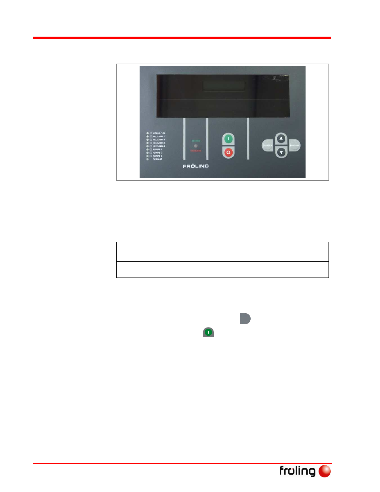
13 Main switch: switches the system on and off
14 HZG 0 / ÖL (Auto/Manual/Off)
15 HEATING 1-4 (Auto/Manual/Off)
16 PUMP 1-3 (Auto/Manual/Off)
17 BLOWER FAN (Auto/Manual/Off)
18 Lambdatronic P 3100 control system with two-row display for showing operating status
19 The corresponding LED illuminates when there is activity from positions 14-17
20 Status LED (Operating Status): - slow, green flashing light: Boiler activated
- fast green flashing light: Boiler deactivated
- red flashing light: Fault
21 Start key: Switch on boiler
22 Stop key: Switch off boiler
23 Back key: Return from a submenu or undo an entry
BACK
24 Up arrow key: Move the arrow up in the menu, increase or activate parameters
25 Down arrow key: Move the arrow down in the menu, decrease or deactivate parameters
26 Enter key: Go to submenus, call up or confirm entries
ENTER
Safety
Safety Information
Page 8
B0190806
I
2
2 Safety
2.1 Safety Information
Non-permitted use!
Incorrect use of the boiler can cause severe injuries and damage!
The instructions and information provided in the instructions
should be observed!
Details on procedure for operation, maintenance and cleaning, as
well as troubleshooting for the boiler are included in the
individual instructions. Any further work should be carried out by
authorised heating engineers or by Fröling customer services.
External influences!
Negative external influences, such as insufficient combustion air or
non-standard fuel can cause serious faults in combustion (e.g.
spontaneous combustion of carbonisation gases or flash fires) which
can in turn cause serious accidents!
Instructions and information for versions and minimum values, as
well as norms and guidelines for heating components in the
instructions must be observed!
Severe injuries and damage can be caused by an inadequate flue gas
system!
Problems with the flue system, such as poor cleaning of the flue pipe
or insufficient chimney draught can cause serious faults in
combustion (such as spontaneous combustion of carbonisation gases
or flash fires)!
You can only be guaranteed of optimum performance from the boiler if the
flue gas system is running smoothly!

Safety
Permitted Uses
Fröling Heizkessel- und Behälterbau Ges.m.b.H, Industriestraße 12, A-4710 Grieskirchen, Austria Page 9
Tel +43 (0) 7248 606-0 Fax +43 (0) 7248 606-600 info@froeling.com www.froeling.com
B0190806
2
2.2 Permitted uses
The boiler should only be operated when it is in full working order.
It should be operated in accordance with the instructions, observing
safety precautions, and you should ensure you are aware of the
potential hazards. Ensure that any faults, which might impact safety are
traced and removed immediately.
The P2 Pellet Boiler is intended exclusively for heating up
heating water. Use only the fuels specified in 2.2.1 below.
The manufacturer or supplier is not liable for any damages
resulting from non-permitted uses.
2.2.1 Permitted fuel
Wood pellets from natural wood with a diameter of 6mm
Applicable standards:
Austria: ÖNORM M 7135 - HP 1 and/or DINplus certification
program
Germany: DIN 51731 - HP 5, DINplus certification program and/or
ÖNORM M 7135 - HP 1
Applies generally:
Before refilling the store, check for pellet dust and clean if necessary.
Non-permitted fuels!
Burning non-permitted fuels lead to a build-up of aggressive
sedimentation and condensation, which can lead to damage to the
boiler and also voids the warranty!
2.2.2 Who can operate the boiler
Only trained operators are permitted to operate the boiler.
No unauthorized access to the boiler room.
Danger: Personal injury and damage to property.
It is the responsibility of the operator to ensure that unauthorized persons,
especially children, are kept away from the boiler.
§

Safety
Design Information
Page 10
B0190806
I
2
2.3 Design Information
It is generally forbidden to carry modifications to the boiler or to change
or deactivate safety equipment.
In addition to the operating instructions and the applicable regulations
for the country in which the boiler will be operated for installation and
operation of the boiler system, all fire, police, and electrical regulations
must be observed.
2.3.1 Official approval and obligation to report
Each heating system must be officially approved.
When installing or modifying a heating system, you must inform the
inspectors from the supervisory authority and get authorisation from the
building authorities.
Austria: Report to the construction authorities of the community or
magistrate
Germany: Report new installations to an approved chimney sweeper and to
the building authorities.
2.3.2 Requirements for heating water
The requirements for heating water are based on the following
standards:
Applicable standards:
Austria: ÖNORM H 5195-1
Germany: VDI 2035
If the system is topped up or refilled:
Prepare (soften) the water to prevent boiler scaling.
2.3.3 Ventilating the Boiler Room
The openings for the supply air and the exhaust air should be arranged
as nearly opposite each other as possible to achieve a good thermal
draught effect.
The supply air must be drawn in directly from outside. The exhaust
air must be discharged directly outside.
Provided they are not contradicted by the relevant building regulations
room where the boiler is to be installed, the following standards apply:
Applicable standards:
- TRVB H 118
- ÖNORM H 5170
§
§

Safety
Design Information
Fröling Heizkessel- und Behälterbau Ges.m.b.H, Industriestraße 12, A-4710 Grieskirchen, Austria Page 11
Tel +43 (0) 7248 606-0 Fax +43 (0) 7248 606-600 info@froeling.com www.froeling.com
B0190806
2
Rule of thumb:
Provide a supply air cross-section of 2 cm2 per kW of boiler rated output,
as per ÖNORM H 5170, but a total cross-section of at least 200 cm
2
2.3.4 Heating System Installation/ Standards
The following standards govern the installation of heating systems:
Applicable standards:
ÖNORM / DIN EN 12828 Heating Systems in Buildings
The following prior standards still apply:
Austria: - Closed systems as per ÖNORM B 8131
- open systems as per ÖNORM B 8130
Germany: - closed systems as per DIN 4751 Part 2
- open systems as per DIN 4751 Part 1
A storage tank with the proper dimensions will guarantee the best boiler
operating values during the entire heating period.
Return feed lift
If the heated water return feed is under the minimum return
temperature, a portion of the heated water outfeed will be mixed in.
Below dew point / condensation forms during operation without
return feed lift!
Condensation water and fuel residue combine to form an aggressive
condensate, leading to damage to the boiler!
Regulations demand the use of a return feed lift!
§

Safety
Design Information
Page 12
B0190806
I
2
2.3.5 Chimney connection / chimney system
The standard EN 303-5 specifies that the entire flue gas system must be
designed to prevent, wherever possible, damage caused by seepage,
insufficient feed pressure and condensation.
It should be noted here that flue gas temperatures of less than 160 K
above room temperature can occur within the permitted operating range
of the boiler.
The flue gas temperatures (when cleaned) and the additional flue gas
values can be found in the technical specification sheets.
Page 12, Boiler data for constructing the flue gas system
Install the connection to the chimney via the shortest path, as far as
possible under 30 – 45°. Insulate the connector.
The entire flue gas system (chimney and connection) must be worked
out as per ÖNORM / DIN EN 13384-1 or prior standards ÖNORM M
7515 / DIN 4705-1.
In addition, local and other legal regulations apply!
The chimney must be approved by a smoke trap sweeper or
chimney sweeper.
As per TRVB H 118 (only in Austria) an explosion flap must be
installed in the flue pipe or in the chimney.
Draught limiter
We recommend that you install a draught limiter 1
Install the draught limiter directly under the mouth of the flue line,
as there is always low pressure there.
Boiler data for constructing the flue gas system
Component Unit P2-10 P2-15 P2-20 P2-25
Flue gas temperature NL °C 150 150 155 160
Flue gas mass flow NL
PL
kg/h
38
12
38
12
51
16
64
20
Flue gas mass flow NL
PL
kg/s
0.0106
0.0033
0.0106
0.0033
0.0142
0.0044
0.0178
0.0056
Feed pressure required NL
PL
Pa
7
4
7
4
7.5
4.5
8
5
Feed pressure required NL
PL
mbar
0.07
0.04
0.07
0.04
0.075
0.045
0.08
0.05
Flue pipe diameter mm 130 130 130 130
NL = Nominal Load, PL = Partial Load
1

Safety
Safety Devices
Fröling Heizkessel- und Behälterbau Ges.m.b.H, Industriestraße 12, A-4710 Grieskirchen, Austria Page 13
Tel +43 (0) 7248 606-0 Fax +43 (0) 7248 606-600 info@froeling.com www.froeling.com
B0190806
2
2.4 Safety Devices
1 STOP key
In case of overheating, shut down the
boiler
The pumps continue to run!
Always end heating with the
STOP key. Never use the main
switch.
2 Key switch (for screw
discharge)
Disengages power from the combustion
unit’s drive components.
CAUTION: The power is still on
in the pellet module!
3 Main switch
For shutting down the entire system
The power to all components is
switched off.
CAUTION: The power is still on
in the pellet module!
4 Safety temperature limiter
(STL)
Page 14, Devices for preventing the
boiler from overheating
5 Fuse Fuse the controls and electrical
components
When changing fuses, fit fuses with
the rated current specified.
2
4
1
3 5

Safety
Safety Devices
Page 14
B0190806
I
2
2.4.1 Devices for preventing the boiler from overheating
Thermal discharge safety device
At around 100 °C a valve opens and sends cold water to the safety
heat-exchanger to decrease the temperature.
Safety Temperature Limiter STL
Stops combustion at a max. boiler temperature of 100 °C. The pumps
continue to run!
As soon as the temperature has gone back down, the STL (1) can
be mechanically unlocked.
Safety valve
Protection against over-heating/ excessive pressure:
When the boiler pressure reaches a maximum of 3 bar, the safety valve
opens and the heating water is released in the form of steam.
2.5 Safety information for installation room
1) Danger of fire due to flammable materials!
No flammable materials should be stored near the boiler.
2) Damage due to impurities in combustion air!
Do not use any hydrogen halides or any cleaning agents containing
chlorine in the room where the boiler is installed.
3) Keep the air suction opening of the boiler free of dust.
4) The room where the boiler is installed must be frost-proof.
1 1

Safety
Other risks
Fröling Heizkessel- und Behälterbau Ges.m.b.H, Industriestraße 12, A-4710 Grieskirchen, Austria Page 15
Tel +43 (0) 7248 606-0 Fax +43 (0) 7248 606-600 info@froeling.com www.froeling.com
B0190806
2
2.6 Other risks
Do not touch the hot surface!
Hot parts and the flue pipe can cause serious burns!
Protective gloves should generally be worn when working on
the boiler.
Only operate the boiler using the handles provided for this
purpose.
Insulate the flue pipes or simply avoid touching them during
operation.
Before carrying out work in the boiler:
Turn off the boiler with the key and allow it to cool down
Then switch off the main switch.
Never turn off the boiler directly with the main
switch!
Do not open the combustion chamber door during operation!
This may cause injury, damage and smoke!
It is forbidden to open the doors behind the insulating door
during operation!
Do not use unauthorised fuel!
Non-standard fuels can cause serious faults in combustion (e.g.
spontaneous combustion of carbonisation gases / flash fires) which
can lead to serious accidents!
Only use fuels specified in the chapter on “Permitted Uses” in
these instructions.

Safety
Emergency procedure
Page 16
B0190806
I
2
2.7 Emergency procedure
2.7.1 System overheating
If the system overheats and the safety devices fail to operate, proceed
as follows:
Keep all the doors on the boiler closed.
Turn off the boiler with the key
Under no circumstances use the main switch!
Open all mixer taps, switch on all pumps.
Fröling heating circuit control takes over this function in
automatic operation.
Leave the boiler room and close the door.
Open any available radiator thermostat valves
If the temperature does not drop, inform the installer or Fröling
customer services:
Page 77, 8.2 Manufacturer address
2.7.2 Smell of flue gas
Smell of flue gas!
Flue gases can cause fatal poisoning!
Keep all the doors on the boiler closed.
Turn off the boiler with the key
Under no circumstances use the main switch!
Air the room where the boiler is installed
Close the fire protection door and doors to living areas.
2.7.3 Fire
Fire!
In case of fire, there is risk of burns and explosions!
Turn off the boiler
Use a tested fire extinguisher for fire class AB to fight the fire
AB powder

Operating the System
Initial startup
Fröling Heizkessel- und Behälterbau Ges.m.b.H, Industriestraße 12, A-4710 Grieskirchen, Austria Page 17
Tel +43 (0) 7248 606-0 Fax +43 (0) 7248 606-600 info@froeling.com www.froeling.com
B0190806
3
3 Operating the System
3.1 Initial startup
Initial startup should be carried out with an authorised installer or with Fröling
customer services.
The individual steps of the initial setup procedure are explained in the
chapter on “Installers and service technicians”
Page 59, 7.4 Initial startup
If condensation escapes during the initial heatup phase, this does not
indicate a fault.
If this occurs, clean up using a cleaning rag.
3.2 Filling/ refilling the store with fuel
Damage and injuries can occur if the store is filled when the boiler is
on!
Turn off the boiler with the key
Allow the boiler to cool down for at least half an hour.
When the boiler has cooled down:
Close all opening to the store to seal out dust
Fill the store with pellets
Only use permitted pellets
Page 9, 2.2.1 Permitted fuel

Operating the system
Heating up the boiler
Page 18
B0190806
s
3
3.3 Heating up the boiler
3.3.1 Switching on the system
Switch on the main switch on the controls
After the system check by the controls, the system is ready for
operation
3.3.2 Switching on the boiler
All selector switches must be set to “Auto”.
Press the key
The heating system is controlled via the control system according
to the selected mode.
3.3.3 Controlling the boiler
See chapter 4 - Lambdatronic P 3100 control system
3.3.4 Switching off the boiler
Press the key
The boiler follows the shut-down program and switches to
“Burner OFF” status.
The control system then only controls the connected heating
components
3.3.5 Switching off the System
ATTENTION! Only switch off when the boiler has cooled
down.
Switch off the main switch on the controls
The controls are switched off
The system components are powered down.
Caution: The power is still on in the pellet module!

Operating the system
Heating up the boiler
Fröling Heizkessel- und Behälterbau Ges.m.b.H, Industriestraße 12, A-4710 Grieskirchen, Austria Page 19
Tel +43 (0) 7248 606-0 Fax +43 (0) 7248 606-600 info@froeling.com www.froeling.com
B0190806
3
3.4 Emergency (Firewood) Operation
The P2 Pellet Boiler allows for emergency manual operation using
firewood.
This requires the “insert set for emergency firewood operation.”
consisting of:
- 1 x insertion grate (1)
- 1 x cover plate (2)
- 4 x combustion chamber
guards (3)
A properly functioning thermal discharge safety device is obligatory!
3.4.1 Modifying the boiler for emergency operation using firewood
Do not carry out modifications when the boiler is hot!
Hot parts and the flue pipe can cause serious burns!
Protective gloves should generally be worn when working on
the boiler.
Only operate the boiler using the handles provided for this
purpose.
Insulate the flue pipes or simply avoid touching them during
operation.
Before carrying out work in the boiler:
Turn off the boiler with the key and allow it to cool down
Then switch off the main switch.
Never turn off the boiler directly with the main
switch!
When the boiler has cooled down:
Remove the combustion set from the
pellet burner
Remove the upper guide plate with
the fuse receptacle
Remove the middle guide plate
1.
1
2
3

Operating the system
Heating up the boiler
Page 20
B0190806
s
3
Exchange the guide plate and replace
as shown
Put the steel cover onto the guide
plate
The combustion gases path over
the guide plates is blocked.
2.
Hang 2 chamber guards each on the
left and right in the combustion
chamber on the bolts provided
3.
Insert the grate
It sits on the angled edges of the
combustion chamber guards.
4.
3.4.2 Filling the combustion chamber with firewood
Place a layer of firewood broken into small pieces on the grate
Place paper, cardboard or similar on top
Fill the rest of the space with firewood
3.4.3 Setting the controls
For emergency firewood operation, the mode must be set to “Firewood
operation” on the controls:
Press the key
ENTER
The arrow on the display
points to “Set”
Press the key
ENTER
Press the key until the arrow
points to mode
For example, winter
operation.
Mode
Winter operation
Set
Error display

Operating the system
Heating up the boiler
Fröling Heizkessel- und Behälterbau Ges.m.b.H, Industriestraße 12, A-4710 Grieskirchen, Austria Page 21
Tel +43 (0) 7248 606-0 Fax +43 (0) 7248 606-600 info@froeling.com www.froeling.com
B0190806
3
Press the
ENTER
key
A question mark appears
The value can be changed
Press the key until firewood
operation is shown on the display
Press the
ENTER
key
An arrow appears
Firewood operation has been
set
Press the
BACK
key 3x
The operating status is
displayed
Press the key
Firewood operation is
activated
Light the paper
3.5 Modifying the boiler for normal operation
Naturally, the procedure to modify the boiler for normal operation is
carried out in the opposite order to the modifications for emergency
operation
Before starting up the automatic pellet burner, check and clean the
boiler. The main points to check are the combustion bowl, the induced
draught fan and the heat exchanger equipment!
Page 35, 5.1.2 Annual Check
Firewood operation
Burner OFF
Mode
Firewood operation
Mode
Winter operation ?

Lambdatronic P 3100 control system
Menu overview
Page 22
B0190806
s
4
4 Lambdatronic P 3100 control system
Winter Operation
Heating
Boiler temp.
Flue gas temp.
ID Fan
Residual O2
Storage.up.
Storage.mi.
Storage.low
DHW tank temp.
Coll. temp.
Oil boiler
Ext. temp.
Flow temp.
Day
Time
Version
Runtime
User name
customer
Set
Error display
Error list
Manual operation
Man. Digi. OUT
Man. Digi. IN
Man. Anal. OUT
System selection
Ash screw Heat
exchanger filling
Boiler type…
System …
Code:
Service
Installer
Customer
Diagram - heating curve
External temperature
Flow temperature
Example of floor heating
Example of radiators
NOTE:
Number and display of parameters depend
on the system selected!
Areas with a grey background are visible
to the customer!
Boiler temp.
Storage tank
DHW tank
Solar
Heating times
Heating circuit 1
Heating circuit 2
Heating circuit 3
Heating circuit 4
Air parameters
Pellets feed
Outfeeder
Boiler times
(transitional operation)
Mode:
Winter operation
RBG 3100
alloc.: 11
Set day
Set time
Clear error
list
Set boiler temperature
Store temp. Heating circuit release
Store up. min. temp.
Set DHW tank temp.
Recharge when HWT below
Start 1. load
End 1. load
Start 2. load
End 2. load
Setup Sol Register
DHW tank target for solar loading
Heating prog. 1
Heating prog. 2
Heating prog. 14
Weekly prog.
Heating curve
Room temp. set value
Chamber control factor
Flow temp. Reduction
Ex.temp.heatlim. reduced amount
Flow temperature max. value
Mixer type
Frost prot.temp. (inside)
Room temp. set value Drawdown mode
Fan MAX
Slide-in MAX
1. Start time for autom. fillung
2. Start time for autom. fillung
Start 1. heating period
End 1. heating period
Start 2. heating period
End 2. heating period
Winter operation
Summer operation
Transitional operation
Firewood operation
Cleaning
Start 1. heating period
End 1. heating period
Start 2. heating period
End 2. heating period
Mo Tu We Th Fr Sa Su
1 1 1 1 4 9 3
Flow temp. At external -10 °C
Flow temp. At external +10 °C
same as heating
circuit 1
same as heating
prog. 1
1

Lambdatronic P 3100 control system
Display messages
Fröling Heizkessel- und Behälterbau Ges.m.b.H, Industriestraße 12, A-4710 Grieskirchen, Austria Page 23
Tel +43 (0) 7248 606-0 Fax +43 (0) 7248 606-600 info@froeling.com www.froeling.com
B0190806
4
4.1 Heating times table
Heating phase 1 Heating phase 2
Heating phase 1 Heating phase
2
Start End Start End Start End Start End
Heating
prog. 1
Heating
prog. 8
Heating
prog. 2
Heating
prog. 9
Heating
prog. 3
Heating
prog. 10
Heating
prog. 4
Heating
prog. 11
Heating
prog. 5
Heating
prog. 12
Heating
prog. 6
Heating
prog. 13
Heating
prog. 7
Heating
prog. 14
You can make a note of your weekly program settings for the individual heating circuits here:
For each day of the week, one of the 14 heating programs can be selected for each heating circuit.
Weekly program Monday Tuesday Wednesday Thursday Friday Saturday Sunday
Heating circuit 1
Heating circuit 2
Heating circuit 3
Heating circuit 4
Notes:

Lambdatronic P 3100 control system
Display messages
Page 24
B0190806
s
4
4.2 Display values
After the main switch has been switched on and the control system has
carried out the system check, the display shows the standard readout
with the mode and operating status.
Winter operation
Burner Off
See 4.2.1 Modes or 4.2.2 Operating statuses
You can use the arrow keys to scroll through the current display values:
Winter operation
Burner Off
Boiler temp. 75°
Flue gas temp. 156°
Flue gas tgt. value 158°
Boiler load 86%
ID Fan 38%
Supply air fan 71%
Slide-in unit 80%
Residual O2 9,0%
O2 regulator 78%
Fill level 73%
Top storage t. 60°
Mid. storage t. 58°
Bot. storage t. 55°
External temp. 8°
Day: Mo 16.10.06
Time: 14:20:36
Version: 24.17
Runtime: 118h
Board temp. 24°
Set boiler
temperature 80°
Choose language
ENGLISH
User
Name CUSTOMER
Mode
Operating status
The parameters, which
are actually displayed,
depend on the boiler
configuration and
operating level.

Lambdatronic P 3100 control system
Display messages
Fröling Heizkessel- und Behälterbau Ges.m.b.H, Industriestraße 12, A-4710 Grieskirchen, Austria Page 25
Tel +43 (0) 7248 606-0 Fax +43 (0) 7248 606-600 info@froeling.com www.froeling.com
B0190806
4
4.2.1 Modes
Winter operation The boiler controls the heating and hot water heating according to the timed
program settings. There is no reduction in temperature the boiler stays at
the same temperature and maintains a constant burn.
Summer operation
Systems without storage
The boiler only controls the hot water heating according to the timed program
settings. There is no reduction in performance the boiler switches to “Burner
Off”.
Summer operation
Systems with stores
The boiler regulates domestic hot water (DHW) heating according to the DHW
tank loading times, which have been set. After heating the domestic hot water,
the boiler switches to “Burner Off”.
Transitional operation
Systems without storage
The boiler produces heat during the specified heating phases (“Boiler times”
menu). Heating and hot water are regulated according to the specified times
(heating times, DHW tank loading times). There is no reduction in temperature
the boiler stays at the same temperature and maintains a constant burn.
When the heating phase ends, the boiler switches to “Burner Off”.
Transitional operation
Systems with stores
If the temperature falls below the “Store up min. temp.”, the boiler is turned on
within the specified store loading times. If the store is fully loaded, the boiler
switches to “Burner Off”. When the parameter “End of 1st or 2nd store loading”
is reached, the boiler also switches to “Burner Off”, even if the store is not fully
loaded.
NOTE: Set a sufficiently large time window (00:00 to 24:00 means that as soon
as the value falls below the parameter “Storage up min” the store is
immediately fully loaded)
NOTE: This is an ideal operating method for systems with storage tanks
Extra heating
Press and hold the key for 5 seconds:
The controls are set to “Override”: the boiler switches on for 4 hours; hot water
heating and heating circuit regulation are active.
Firewood operation This mode is for emergency firewood operation. The pellet feeding system is
deactivated.
Cleaning The boiler turns off the combustion system as directed (“Burner Off” status)
Then the ID fan, combustion air fan, heat-exchanger system and ash screw are
controlled according to the program.
After the cleaning has finished, reset to original mode.
Chimney sweeper
Press and hold the key and the
BACK
key for 5 seconds
The chimney sweeper program for boiler measurement is started.
The system is operated for 30 minutes at nominal load. For this aim the
maximum boiler temperature, the maximum heating circuit flow temperature
and the DHW tank loading are released.
Switched off
Press the key
The boiler turns off following the shutdown routine. The system now only
regulates the connected heating components
For systems with a storage tank, always select transitional operation!

Lambdatronic P 3100 control system
Display messages
Page 26
B0190806
s
4
4.2.2 Operating statuses
Preparation The induced draught fan is switched on.
Heating up The combustion bowl is filled with pellets. The supply air fan, the induced
draught fan and the igniter are turned on.
Pre-heating The pellets are pre-warmed with the fan-assisted ignition and a bed of embers
is formed. No fuel slide-in unit.
Ignition The pellets are ignited with the fan-assisted ignition. The flame is spread across
the whole combustion bowl. The supply air fan, the ID fan, and the slide-in unit
can be set in the “Ignition” menu.
Heating The Lambdatronic controls combustion according to the target boiler values.
Constant burn The boiler has reached the specified temperature and there is no reduction in
temperature. The supply air fan, the ID fan, and the slide-in unit are
deactivated.
STBY. Wait 1 The supply air fan and perhaps the ID fan are running too slowly (“Fan during
shut down”) to burn the remaining pellets. No slide-in.
STBY. Feed 1 Safety slide-in after the first wait time. As with status “STBY. Wait 1”, but
with slide-in, in accordance with the parameter, “Feed off”.
STBY. Wait 2 The supply air blower fan and the induced draught are switched off, no slide-in.
STBY. Feed 2 Safety slide-in after the second wait time. As with status “STBY. Wait 2”, but
with slide-in, in accordance with the parameter, “Feed off”.
Fault ATTENTION - Fault!
Error correction 20 min When the faults “Ignition failed”, “Safety time elapsed too low”, “Safety time
O2 too high” and “Pressure monitor comb chamb” are acknowledged, error
correction starts. When error correction has been carried out (approx. 20 min)
the warning, “Clean/ check burner”, is shown on the display. The warning can
only be acknowledged with the enter key after checking the burner.
Burner Off
This status is reached by pressing the key when store or DHW tank loading
has finished, or after acknowledging an error message, which requires a
shutdown. All parts of the boiler stop. The system now only regulates the
connected heating components.

Lambdatronic P 3100 control system
Menus and parameters
Fröling Heizkessel- und Behälterbau Ges.m.b.H, Industriestraße 12, A-4710 Grieskirchen, Austria Page 27
Tel +43 (0) 7248 606-0 Fax +43 (0) 7248 606-600 info@froeling.com www.froeling.com
B0190806
4
4.3 Changing parameters and values
Values are changed as follows:
Save value and go back
ENTER
Unlock parameter for processing Larger
ENTER
Smaller
BACK
Back without saving
4.4 Menus
At the client level the following menus are available
SET ... Boiler temp. ... Page 28, Setting boiler temperature
Storage tank ... Page 28, Set storage tank temperatures
DHW tank ... Page 28, Set DHW tank temperatures
Heating times ... Page 29, Setting heating times
Heating circuit 1 ...
Heating circuit 2 ...
Heating circuit 3 ...
Heating circuit 4 ...
Page 29, Allocating heating times to heating
circuits
Pellets feed ... Page 30, Setting the runtime of the ash screw
Outfeeder ... Page 30, Setting the pellet filling time
Boiler times ... Page 30, Setting boiler times
Boiler temp.
should be 70°?
Boiler temp.
should be 70°

Lambdatronic P 3100 control system
Menus and parameters
Page 28
B0190806
s
4
4.4.1 Settings menu
In the “Settings” operating menu the most important parameters and
values for the system can be changed:
Setting boiler temperature
Boiler temp. ... Boiler temp. should be 80°C The boiler temperature is regulated to this
temperature
Set storage tank temperatures
Storage tank ... Storage temp. heat
circ. launch 30°C
Only for systems with storage tanks
Minimum temperature for releasing the
heating circuit. (Sensor 1)
Store up. min. temp. 60°C Upper store temperature, below which the
boiler is started in transitional operation.
Set DHW tank temperatures
DHW tank ... Set DHW temp 55°C When the specified temperature is reached
in the DHW tank, the DHW tank loading
pump switches off.
Desired DHW tank 2
temperature 60°C
When the specified temperature is reached
in DHW tank 2, DHW tank loading pump 2
switches off.
Reload when the DHW
tank is below 45°C
Reloading of the DHW tank is authorised
when the DHW tank temperature is below
this level.
Reload when the DHW
tank is below 45°C
Reloading of the second DHW boiler is
authorised when the DHW boiler
temperature is below this level.
Start of 1st loading 05:00 Start of authorisation for 1st DHW tank
loading session
End of 1st loading 08:00 End of authorisation for 1st DHW tank
loading session
Start of 2nd loading 15:00 Start of authorisation for 2nd DHW tank
loading session
End of 2nd loading 18:00 End of authorisation for 2nd DHW tank
loading session
Only heat once a day N “Y” prevents heating up several times in
one day
Legionella heating 65° Y The DHW tank is heated to at least 65°C
once a week
Legionella heating day Mo Day of the week for Legionella heating.

Lambdatronic P 3100 control system
Menus and parameters
Fröling Heizkessel- und Behälterbau Ges.m.b.H, Industriestraße 12, A-4710 Grieskirchen, Austria Page 29
Tel +43 (0) 7248 606-0 Fax +43 (0) 7248 606-600 info@froeling.com www.froeling.com
B0190806
4
Setting heating times
Heating times ... Heating prog. 1 ... Heating phase 1 start 06:00
Heating phase 1 end 11:00
Heating phase 2 start 15:00
Heating phase 2 end 23:00
Lowered outside the
specified heating times.
Heating prog. 2
:
:
:
Heating prog. 14...
2 heating phases each, like heating prog. 1.
You can program up to 14 heating times each with two
heating phases.
These heating times can be allocated to the individual
days of the week under the parameter “Weekly program”
for the heating circuits 1-4.
Allocating heating times to heating circuits
Heating circuit 1 ... Weekly program
Mo Tu We Th Fr Sa Su
1 1 3 1 1 2 5
Allocating heating times 1- 14 to
the individual days of the week
for heating circuit 1
Heating curve ... Flow temp. at
external -10°C 60°C
Flow temp. at
external +10°C 40°C
These two parameters are the
work points for adjusting the
heating curve to the relevant
system
Room temp.
set value 21°C
Desired room temperature
during heating (only with
remote control).
Room temp. set
value Drawdown
mode 16°C
Desired room temperature
during drawdown mode (only
with remote control).
Ex.temp.
heating limit 18°C
If the external temperature
exceeds this value during the
heating phase, the heating
circuit pump and mixer are
switched off.
Outside temp
Heating limit
Drawdown
mode 7°C
If the external temperature
exceeds this value during
drawdown mode, the heating
circuit pump and mixer are
switched off.
Heating circuit 2 ...
Heating circuit 3 ...
Heating circuit 4 ...
Settings as with heating circuit 1
Flow temperature
External temperature
Example of floor
heating
Example of
radiators

Lambdatronic P 3100 control system
Menus and parameters
Page 30
B0190806
s
4
Setting the runtime of the ash screw
Pellet feed unit ... Ash screw Runtime 5s Runtime of the ash screw
Setting the pellet filling time
Outfeeder ... Start time for 1st filling 15:00 1. Start time for filling.
This is only carried out if the fill level in the
container is under 85%.
Start time for 2nd filling 15:00 2. Start time for filling.
This is also only carried out if the fill level in
the container is under 85%.
Setting boiler times
Boiler times ... Start 1. Storage tank load 05:00
End 1. Storage tank load 10:00
Start 2. Storage tank load 17:00
End 2. Storage tank load 22:00
For systems with storage tank in
transitional operation!
Within this time window the boiler is
activated if the upper storage
temperature falls below the minimum
temperature.
Start 1. heating period 05:00
End 1. heating period 08:00
Start 2. heating period 17:00
End 2. heating period 21:00
For systems without storage tank in
transitional operation!
The boiler is activated within this time
window.
Important! DHW tank loading times
must be within the time window of the
boiler times.
Start EOS 1 08:00 1. Start time for heat exchanger cleaning
The boiler must have been in operation for
at least 2 hours since the last cleaning
Start EOS 2 15:00 2. Start time for heat exchanger cleaning
The boiler must have been in operation for
at least 2 hours since the last cleaning
4.4.2 Manual operation menu
Manual operation is used operate the relevant unit by hand:
ASH SCREW OFF For switching the ash screw on and off manually
EOS OFF For switching the heat exchanger on and off manually
FILLING OFF After activating the parameter, the container is filled with fuel, regardless of fill
level, until the function is turned off or the switch point of the level sensors is
reached. When the level sensor reaches its limit value, the fill level value is set
to 100%.
Important! Parameter only for discharge systems with suction unit

Boiler maintenance
Inspection, cleaning and maintenance
Fröling Heizkessel- und Behälterbau Ges.m.b.H, Industriestraße 12, A-4710 Grieskirchen, Austria Page 31
Tel +43 (0) 7248 606-0 Fax +43 (0) 7248 606-600 info@froeling.com www.froeling.com
B0190806
5
5 Boiler maintenance
Working on electrical components.
Serious injuries from electric shocks!
Work on electrical components should only be carried out by authorised
technicians!
Do not carry out maintenance when the boiler is hot!
Hot parts and the flue pipe can cause serious burns!
Protective gloves should generally be worn when working on
the boiler.
Only operate the boiler using the handles provided for this
purpose.
Insulate the flue pipes or simply avoid touching them during
operation.
Before starting any maintenance work:
Turn off the boiler with the key and allow it to cool down
or
set the boiler to “Cleaning” mode
The boiler shuts down as directed and controls the ID fan,
combustion air fan, heat exchanger system and ash screw
according to the program.
Important! After maintenance work, reset the controls to
the original mode
Non-permitted cleaning and maintenance!
Incorrect or insufficient cleaning and maintenance of the boiler can
cause serious faults in combustion (e.g. spontaneous combustion of
carbonisation gases / flash fires) and this can lead to serious
accidents!
Clean the boiler according to the instructions in the instruction
manual!

Boiler maintenance
Inspection, cleaning and maintenance
Page 32
B0190806
s
5
5.1 Inspection, cleaning, and maintenance
Regular cleaning of the boiler extends its life and is a basic
requirement for smooth running.
So clean the boiler regularly!
5.1.1 Inspection
Checking the combustion chamber and pellet burner
Check the boiler regularly for dirt:
Shut down the boiler using the
key and allow it to cool down
Open the insulating door and
combustion chamber door
Cleaning the combustion chamber
and pellet burner
Page 34, Cleaning the pellet burner
Checking the level of the ash
The amount of ash depends on the boiler’s output!
P2 ash drawer module:
Open insulation door
Loosen the star-shaped screw knob
on the front ash drawer by turning it
to the left
Pull out the ash drawer and check the
level
Empty the ash drawer if necessary
Page 33, Emptying the ash
drawer (P2 ash drawer module)
P2 ash screw module:
Open insulation door
Open the clamps on the left and right
Remove the lid and check the ash
level
Empty the ash container if necessary
Page 33, Emptying the ashcan
(P2 ash screw module)

Boiler maintenance
Inspection, cleaning and maintenance
Fröling Heizkessel- und Behälterbau Ges.m.b.H, Industriestraße 12, A-4710 Grieskirchen, Austria Page 33
Tel +43 (0) 7248 606-0 Fax +43 (0) 7248 606-600 info@froeling.com www.froeling.com
B0190806
5
Emptying the ash drawer (P2 ash drawer module)
Loosen the star-shaped screw knob on the front ash drawer by
turning it to the left
Pull out the front ash drawer
Insert the ash drawer hook (provided) at the rear cross handle of the
ash drawer
Take the ash drawer to the emptying location
Only dispose of the ash if there are no hot embers left and the
ash has cooled.
Insert the furnace tool at the handle of the rear ash drawer
Pull the ash drawer forward
Insert the ash drawer hook at the rear cross handle like before and
take the ash drawer to the emptying location
Emptying the ashcan (P2 ash screw module)
Open insulation door
Remove the ash container from the bottom end of the ash screw
channel and take it to the emptying location
Only dispose of the ash if there are no hot embers left and the
ash has cooled.
Open the clamps, remove the lid and empty the ash container
Before positioning the ash container at the ash screw channel, the
flap must be opened!

Boiler maintenance
Inspection, cleaning and maintenance
Page 34
B0190806
s
5
Cleaning the pellet burner
Open the insulating door and
combustion chamber door
Remove the combustion mount
Tip the combustion mount
The ash falls past the pellet
burner and into the ashcan
Clean the pellet burner using the ash
scraper
The slit must be free of ash!
Checking the thermal discharge safety device
Check the seal of the discharge valve
The discharge pipe must not drip
Exception: boiler temperature > 95 °C
If water is dripping from the discharge pipe:
Clean the discharge safety device or have
the installer replace it if necessary
Check the safety valve as per the
manufacturer’s specifications

Boiler maintenance
Inspection, cleaning and maintenance
Fröling Heizkessel- und Behälterbau Ges.m.b.H, Industriestraße 12, A-4710 Grieskirchen, Austria Page 35
Tel +43 (0) 7248 606-0 Fax +43 (0) 7248 606-600 info@froeling.com www.froeling.com
B0190806
5
Checking the system pressure
Read off the system pressure on the
pressure gauge
The value must be over the prestressed pressure of the
expansion tank by 20%
Expansion tank operating
instructions
If the system pressure drops, refill the
water
If this occurs frequently, the
heating system does not have a
good seal!
Inform your installer!
If large pressure fluctuations are
observed, have the expansion tank
checked
5.1.2 Annual Check
Carry out yearly, or at least after 1500 hours of operation!
Checking the heat-exchanger and flue gas collection chamber
Remove the two screws on the
insulting cover using a Phillips
screwdriver
Remove the insulating cover
Loosen screw at the cleaning port
cover
Remove the cleaning cover
Clean the flue gas collection
chamber and the opening to the
induced draught fan with a brush
Remove any soot which has fallen
in
We recommend that you use an
ash vacuum

Boiler maintenance
Inspection, cleaning and maintenance
Page 36
B0190806
s
5
Clean the flue gas sensors
Remove the insulating cover
Page 35, Checking the heat-
exchanger and flue gas
collection chamber
Release the threaded pin and
remove the sensing element from
the flue gas pipe
Wipe off the flue gas sensor with a
clean cloth
Slide in the flue gas sensing
element and secure it hand-tight
using the threaded pin
Checking the primary air pipes
Open the insulating door and
combustion chamber door
Remove the combustion mount
Check primary air pipes(1) for air
flow
If necessary, clean the pipes
Checking the gearing
At the back of the boiler: Ash screw gearing
There must not be any leaking lubrication!
Cleaning the induced draught ventilator
Detach the induced draught
ventilator on the back side of the
boiler
Check for dirt and damage
Clean the blower wheel with a soft
brush or paint brush
Don’t move the balancing
weights on the blower wheel!
1

Boiler maintenance
Inspection, cleaning and maintenance
Fröling Heizkessel- und Behälterbau Ges.m.b.H, Industriestraße 12, A-4710 Grieskirchen, Austria Page 37
Tel +43 (0) 7248 606-0 Fax +43 (0) 7248 606-600 info@froeling.com www.froeling.com
B0190806
5
Clean the smoke flue pipe
Clean the connecting pipe between the boiler and the chimney
regularly with a chimney sweeping brush
Depending on the layout of the flue pipes and the chimney
draught cleaning yearly may not be enough!
Checking the draught controller flap and explosion flap
Check the draught controller flap and explosion flap for ease of
operation
Maximum permissible setting: 25 Pa
Ideal setting: 20 Pa
Checking the combustion chamber door
Close the combustion chamber door
and check its seal
Check fibre-glass seal (1) for
perfect alignment on the door frame
Imprint in the fibre-glass seal
If the seal is coloured black at several points or the imprint is
interrupted:
The seal is no longer efficient.
Tighten the door latches or replace the fibre-glass seal
Clean the bypass line (only for systems with suction unit)
Loosen the hose clips on the T-piece and the rotary valve
Detach the bypass line (1) and double-nippled pipe (2)
Check that the double-nippled pipe and bypass line are clear and if
necessary clean them with compressed air
Remove deposits from the thread (3) of the pellet valve
Depending on the length of the suction hose and the fuel type,
cleaning yearly may not be sufficient!
2
1
3
1

Boiler maintenance
Inspection, cleaning and maintenance
Page 38
B0190806
s
5
5.2 Maintenance Agreement / Customer services
Guarantee a long service-life with a service agreement!
Regular maintenance and servicing by a heating specialist will ensure a
long, trouble-free service life for your heating system.
Regular servicing will ensure that your system stays environmentfriendly and operates efficiently and cost-effectively.
For this reason, FRÖLING offers a service agreement, which optimises
operating safety. Please see the details in the accompanying guarantee
certificate.
Your Fröling customer service office is also glad to provide consultation.
5.3 Replacement parts
With Fröling original replacement parts in your boiler, you are using
parts, which are perfectly coordinated to work together. As the parts fit
together so well, installation times are shortened and lifespan is
maintained.
Installing non-original parts voids the guarantee!
Only replace components or parts with original replacement parts

Troubleshooting
Fröling Heizkessel- und Behälterbau Ges.m.b.H, Industriestraße 12, A-4710 Grieskirchen, Austria Page 39
Tel +43 (0) 7248 606-0 Fax +43 (0) 7248 606-600 info@froeling.com www.froeling.com
B0190806
6
6 Troubleshooting
6.1 General faults in power supply
Error Cause of error Error correction
Nothing is shown on the
display
No power to the controls
General power failure
FI circuit breaker or line
protection is switched off
Main switch is turned off
Defective fuse in the controls
Switch on the FI circuit breaker or line
protection
Turn on the main switch
Replace fuse – note current (10AT)
6.1.1 System procedure following power failure
When the power supply has been restored the boiler returns to the
previously specified mode and is controlled according to the specified
program.
EXCEPTION:
If the boiler was at operating status “Heating up”, “Pre-heating” or
“Ignition” troubleshooting is started automatically. When error
correction has been carried out (approx. 20 min) the warning, “Clean/
check burner”, is shown on the display. The warning can only be
acknowledged after checking the burner.
6.2 Excessive temperature
The safety temperature limiter shuts down the boiler when it reaches a
temperature of approx. 100°C. After the boiler has cooled down, the
safety temperature limiter (1) must be manually unlocked:
Unscrew the cap on the safety temperature limiter
Reset the safety temperature limiter by pressing with a screw-driver.
1
Troubleshooting
Page 40
B0190806
s
6
6.3 Faults with a fault message
If a fault has occurred and has not yet been cleared:
Status LED (1) flashes red
A fault message is shown on the display (2)
An internal distinction is made between 3 types of message:
Warning (W) Boiler continues running
Error (E) Boiler follows shutdown procedure
Fault (F) Boiler shuts down immediately, heating circuit controls
and pumps remain active
6.3.1 Procedure for fault messages
Find and eliminate the error.
Acknowledge the error by pressing the
ENTER
key
Restart the boiler with the key
1
2

Troubleshooting
Fröling Heizkessel- und Behälterbau Ges.m.b.H, Industriestraße 12, A-4710 Grieskirchen, Austria Page 41
Tel +43 (0) 7248 606-0 Fax +43 (0) 7248 606-600 info@froeling.com www.froeling.com
B0190806
6
6.4 Error message list
Error texts in alphabetical order:
Error text Code Type
Cause of error Error correction
Outdoor sensor temp.
false
036 W • Sensor signal damaged Check sensor and sensor cable
DHW temp. false 006 W • Sensor signal damaged Check sensor and sensor cable
DHW temp.2 false 037 W • Sensor signal damaged Check sensor and sensor cable
Clean /check burner 049 W Signals successful automatic troubleshooting
NOTE: can only be cleared by checking and cleaning the burner
Acknowledge warning
After you have done this, open the insulating door and
combustion chamber door
Clean embers, fuel and slag from the pellet burner (see
chapter on maintenance)
Clean the flue gas guide in the boiler up to the mouth of the
chimney
Empty the ash drawer
Stoker error 030 F Gravity shaft level sensor still
recognises material after 10
minutes of stoker running
time:
• Bridge formation in the
gravity shaft
• Sensor incorrectly set
• Stoker not feeding
Break up the bridge of fuel,
remove foreign bodies if
necessary
Readjust the sensor
Check stoker drive
Remote control 1 error 004 W • Sensor signal damaged Check sensor and sensor cable
Remote control 2 error 005 W • Sensor signal damaged Check sensor and sensor cable
Remote control 3 error 025 W • Sensor signal damaged Check sensor and sensor cable
Remote control 4 error 026 W • Sensor signal damaged Check sensor and sensor cable

Troubleshooting
Page 42
B0190806
s
6
Error text Code Type
Cause of error Error correction
Excess pressure in
combustion chamber
Acknowledge error Pressure monitor comb
chamb
029 F
NOTE: After acknowledging the error, error correction starts
immediately. Keep the doors of the boiler closed!
After error correction starts, check if the induced draught fan is
running
CAUTION! In case of defective induced draught fan inform the
heating engineers or Fröling customer services!
When error correction has been automatically carried out (approx.
20 min) the warning, “Clean/ check burner”, is shown on the
display.
After you have done this, open the insulating door and
combustion chamber door
Clean embers, fuel and slag from the pellet burner
(see chapter on maintenance)
Clean the flue gas guide in the boiler up to the mouth of the
chimney
Empty the ash drawer
Acknowledge warning
Door open -
Empty ash box
040 W Insulating doors are open for
more than 10 minutes during
“HEATING” status!
• The door contact switch
does not close
• Insulating doors not
closed
• Ash box full
Check or adjust switch
Check insulating doors
Empty ash box
Boiler return temp false 007 W • Sensor signal damaged Check sensor and sensor cable
Boiler temp. false 001 W • Sensor signal damaged Check sensor and sensor cable
Solar return temp false 035 W • Sensor signal damaged Check sensor and sensor cable
Comm. to pellet module
false
016 S • Data exchange with pellet
module interrupted
Check cable / plug
Check fuse
Check storage room (for
automatic universal
suction system)
041 S The MAX sensor is not
reached after 10 minutes of
suction per probe:
• No pellets in the suction
probe
• Hose, probe or hose
connections blocked
• Sensor incorrectly set
• Switch motor damaged
Refill pellets in store
ATTENTION! Do not feed any
pellets into the pellet burner
manually - danger of flash fires!
Remove blockage, shake the
hose, if necessary remove
foreign bodies, check pellet
length
Readjust the sensor
Check the plug connection to
the motor
Oil boiler temp. false 011 W • Sensor signal damaged Check sensor and sensor cable

Troubleshooting
Fröling Heizkessel- und Behälterbau Ges.m.b.H, Industriestraße 12, A-4710 Grieskirchen, Austria Page 43
Tel +43 (0) 7248 606-0 Fax +43 (0) 7248 606-600 info@froeling.com www.froeling.com
B0190806
6
Error text Code Type
Cause of error Error correction
Store temp. up. false 008 W • Sensor signal damaged Check sensor and sensor cable
Store temp. mid. false 010 W • Sensor signal damaged Check sensor and sensor cable
Outfeed system error
(with screw discharge unit)
027 S Gravity shaft level sensor
does not recognise any
material for 60 minutes:
• No pellets in trough
• Bridge formation over
trough
• Sensor incorrectly set
• Discharge screw drive is
not working
Refill pellets in store
ATTENTION! Do not feed any
pellets into the pellet burner
manually - danger of flash fires!
Break up blocks of fuel, check
length of pellets
Readjust the sensor
Check drive
Check/clean outfeed
system (for screw suction
systems)
For information on errors in
manual universal suction
systems see the next page!
021 S For screw suction
systems:
The MAX sensor is not
reached after 45 minutes of
suction:
• No pellets in trough
• Bridge formation over
trough
• Hose or hose connections
blocked
• Sensor incorrectly set
• Screw drive not working
Jam sensor is covered for
longer than 5 minutes:
• Suction point is blocked
Refill pellets in store
ATTENTION! Do not feed any
pellets into the pellet burner
manually - danger of flash fires!
Break up blocks of fuel, check
length of pellets
Remove blockage, shake hose
Readjust the sensor
Check drive
Clear blockage and remove
foreign bodies if necessary,
check pellet length

Troubleshooting
Page 44
B0190806
s
6
Error text Code Type
Cause of error Error correction
Check/clean outfeed
system (for manual
universal suction systems)
For information on errors in
the screw suction system
see the previous page!
021 S For manual universal
suction systems:
The MAX sensor is not
reached after 15 minutes of
suction at the probe:
• No pellets at the suction
probe
• Hose, probe or hose
connections blocked
•
• Sensor incorrectly set
Refill pellets in store
Remove blockage, shake the
hose, if necessary remove
foreign bodies, check pellet
length.
Install interchange unit on the
other probe
Readjust the sensor
Return temp low too long
015 W • Return feed temperature
too cold
Check return feed lift, check
sensor
Note: Bypass pump with the speed
control; always operate at
maximum power level!
Inform heating engineers or
Fröling customer services
Key switch engaged 028 S For direct screw discharge:
• key switch was turned off
For suction discharge:
• Handle of X9 connection
of the pellet module not
positioned
Turn the key switch on again.
Set handle at connection X9
See 7.3.2 Pellet module with
suction system
Safety temp. limiter
released
000 S Boiler has overheated,
substantial reduction in heat
consumption:
• Heating and pump
switches have gone off.
• Pump suddenly stops
• Slide valves/cut-offs
closed.
Set switch back to “AUTO”
Check pump
Reopen slide valves/cut-offs
Note: After cooling down, the
safety temperature limiter must be
released
See 6.2 Excessive
temperature

Troubleshooting
Fröling Heizkessel- und Behälterbau Ges.m.b.H, Industriestraße 12, A-4710 Grieskirchen, Austria Page 45
Tel +43 (0) 7248 606-0 Fax +43 (0) 7248 606-600 info@froeling.com www.froeling.com
B0190806
6
Error text Code Type
Cause of error Error correction
The value for the parameter,
“Min. boiler flue temp dif.” fell
below the specified level for
longer than the safety time.
Acknowledge error
NOTE: After acknowledging the error, error correction starts
immediately. Keep the doors of the boiler closed!
After error correction starts, check if the induced draught fan is
running
CAUTION! In case of defective induced draught fan inform the
heating engineers or Fröling customer services!
When error correction has been automatically carried out (approx.
20 min) the warning, “Clean/ check burner”, is shown on the
display.
After you have done this, open the insulating door and
combustion chamber door
Clean embers, fuel and slag from the pellet burner (see
chapter on maintenance)
Clean the flue gas guide in the boiler up to the mouth of the
chimney
Empty the ash drawer if necessary
Acknowledge warning
“Insufficient safety time
elapsed”.
014 F
• Insufficient pellets fed
into combustion bowl
• Bridge formation over
trough
• Sensor incorrectly set
• Stoker not feeding
Refill pellets in storage tank,
check discharge and stoker
ATTENTION! Do not feed any
pellets into the pellet burner
manually - danger of flash fires!
Break up blocks of fuel, check
length of pellets
Readjust the sensor
Check stoker drive

Troubleshooting
Page 46
B0190806
s
6
Error text Code Type
Cause of error Error correction
Oxygen content is greater
than the “Remaining O2 shut
down” parameter - duration
longer than safety time (in
the HEATING state):
Acknowledge error
NOTE: After acknowledging the error, error correction starts
immediately. Keep the doors of the boiler closed!
After error correction starts, check if the induced draught fan is
running
CAUTION! In case of defective induced draught fan inform the
heating engineers or Fröling customer services!
When error correction has been automatically carried out (approx.
20 min) the warning, “Clean/ check burner”, is shown on the
display.
After you have done this, open the insulating door and
combustion chamber door
Clean embers, fuel and slag from the pellet burner (see
chapter on maintenance)
Clean the flue gas guide in the boiler up to the mouth of the
chimney
Empty the ash drawer if necessary
Acknowledge warning
Safety time
O2 too high
039 F
• Wrong air in boiler
• Insufficient pellets fed
into combustion bowl
• Bridge formation over
trough
• Sensor incorrectly set
• Stoker not feeding
Check seal on ash box and
front doors
Check seal on heat exchanger
cover
Check that lambda probe is
fitted firmly
Refill pellets in bunker, check
discharge and stoker
ATTENTION! Do not feed any
pellets into the pellet burner
manually - danger of flash fires!
Break up the bridge, check
pellet length
Readjust the sensor
Check stoker drive
Flow temp 1 false 002 W • Sensor signal damaged Check sensor and sensor cable
Flow temp 2 false 003 W • Sensor signal damaged Check sensor and sensor cable
Flow temp 3 false 023 W • Sensor signal damaged Check sensor and sensor cable
Flow temp 4 false 024 W • Sensor signal damaged Check sensor and sensor cable

Troubleshooting
Fröling Heizkessel- und Behälterbau Ges.m.b.H, Industriestraße 12, A-4710 Grieskirchen, Austria Page 47
Tel +43 (0) 7248 606-0 Fax +43 (0) 7248 606-600 info@froeling.com www.froeling.com
B0190806
6
Error text Code Type
Cause of error Error correction
Boiler remains in “IGNITE”
state longer than the
“Ignition time max”:
Acknowledge error
NOTE: After acknowledging the error, error correction starts
immediately. Keep the doors of the boiler closed!
After error correction starts, check if the induced draught fan is
running
CAUTION! In case of defective induced draught fan inform the
heating engineers or Fröling customer services!
When error correction has been automatically carried out (approx.
20 min) the warning, “Clean/ check burner”, is shown on the
display.
After you have done this, open the insulating door and
combustion chamber door
Clean embers, fuel and slag from the pellet burner (see
chapter on maintenance)
Clean the flue gas guide in the boiler up to the mouth of the
chimney
Empty the ash drawer if necessary
Acknowledge warning
Ignition failed 013 F
• Too few pellets in
combustion bowl
• Defective ignition
• Stoker not feeding
Refill pellets in storage tank,
check discharge and stoker
ATTENTION! Do not feed any
pellets into the pellet burner
manually - danger of flash fires!
Have the ignition checked by
professionals
Check stoker drive

Installers and service technicians
Electrical Connection
Page 48
B0190806
s
7
7 Installers and service technicians
7.1 Connection layout of the boards
A
W
W
W
H
H
H
PEL
L
L1
L1
+L
+L
+R
+R
P2
P2
Y/P3
Y/P3
+US
+US
GND
GND
RXD
RXD
TXD
TXD
N
Mains
ID Fan
Pump 2
Pump 1
Pump 3
Burner/
HCP 0
Primary air
DCS
Door contact switch
Sensor 3
Sensor 2
Sensor 1
Sensor 4
Sensor 5
0
N
PE1 PE2
A
W
H
A
A
HCP/ Oil
Lambda
board
3100
(optional)
View of lower level
3100
control
Ribbon cable
to extension board 1
L
N
L
N
L
N
L
N
whi 12VAC
-
black
+
PEL
Power supply of motherboard
NL LL
D
I
S
P
L
A
Y
E
P
R
O
M
Trans-
former
Pump 1
Pump 3
NLLL
NE1
LE1
NE2LE2
Pump 2
Blower
NL, LL, PEL ....Power supply for the
Lambda board
NE1, LE1, PE1 ....Power supply for
extension board 1
Mother
board
3100
W
H
A
JP2
JP1
Follow the connection instructions!
Lambda
probe
e.g.: RGB,
visualisation
e.g.: Pellet
module
User
extension
Device
extension
green-yellow
blue
red
Flue gas sensor
Boiler sensor
FG Sensor
BS Sensor
Side view of switch
Manual
BLOWER
PUMP 3
PUMP 2
PUMP 1
HEATING 4
HEATING 3
HEATING 2
HEATING 1
HEATING 0/ OIL
Power supply
Power supply
for pellet module
Secondary
air
Manual (M) - WHITE
Root (R) - BROWN
Automatic (A) - VIOLET
Ribbon cable
to extension board 2
NE2, LE2, PE2 ....
extension board 2
Power supply for
whi 12VAC

Installers and service technicians
Electrical Connection
Fröling Heizkessel- und Behälterbau Ges.m.b.H, Industriestraße 12, A-4710 Grieskirchen, Austria Page 49
Tel +43 (0) 7248 606-0 Fax +43 (0) 7248 606-600 info@froeling.com www.froeling.com
B0190806
7
HCP 2
Heating circuit
pump 2
HCP 1
Sensor 9
Sensor 7
Sensor 8
Sensor 6
OF 4
Outfeed sensor 4
EB 3
Extension board 3
EB 4
Extension board 4
OF 3
Outfeed sensor 3
OF 1
Outfeed sensor 1
ES 1
External sensor 1
OF 2
Outfeed sensor 2
RC 1
Remote control 1
RC 2
Remote control 2
Mixer 2
Heating 2
Heating 1
PE2
PE1N2N1L2L1
Power supply of motherboard
3
1
0
0
3
1
0
0
L
N
L
N
L
N
L
N
OPEN
CLOSED
N
N
N
N
View of upper level
W
H
A
W
H
A
W
H
A
W
H
A
J
P
2
J
P
2
J
P
1
J
P
1
Mixer 1
OPEN
CLOSED
Extension board 1
Heating 4
Heating 3
Ribbon cable
from motherboard
Heating circuit
pump 1
Ribbon cable
from motherboard
Extension board 2
Power supply of motherboard
HCP 4
Heating circuit
pump 2
HCP 3
Mixer 4
OPEN
CLOSED
Mixer 3
OPEN
CLOSED
Heating circuit
pump 1
Side view of switch
Manual
BLOWER
PUMP 3
PUMP 2
PUMP 1
HEATING 4
HEATING 3
HEATING 2
HEATING 1
HEATING 0/ OIL
Manual (M) - WHITE
Root (R) - BROWN
Automatic (A) - VIOLET

Installers and service technicians
Electrical Connection
Page 50
B0190806
s
7
7.2 Connection instructions
Working on electrical components.
Serious injuries from electric shocks!
Work on electrical components should only be carried out by authorised
technicians!
7.2.1 Mains connection
L, N, PE power supply for the whole control, cable width 2.5 mm²
L, L1, N, PE power supply for the pellet module
(L1 = via safety temperature limiter controlled cable L)
Caution: Do not connect phase (L) of the power supply to terminal
L1!
Pellet module connection:
Pelletsmodul Lambdatronic 3100
L-STB L1
PE PE
N N
L L
7.2.2 Heating circuit pumps for floor or wall heating
In addition to the temperature limit by the control, the following is
required for safety reasons:
A flow contact thermostat must also be connected upstream of the
respective heating circuit pump.
Feed cable
L1
PE
N
L
Lambdatronic
P 3100
Cable to pellet module

Installers and service technicians
Electrical Connection
Fröling Heizkessel- und Behälterbau Ges.m.b.H, Industriestraße 12, A-4710 Grieskirchen, Austria Page 51
Tel +43 (0) 7248 606-0 Fax +43 (0) 7248 606-600 info@froeling.com www.froeling.com
B0190806
7
7.2.3 Jumper setting for solar control
With the solar control the mixer 3 and mixer 4 outputs are used as
pump outputs.
The jumpers on expansion board 2 must be set as shown in the table:
Jumpers on expansion board 2 System
Set JP1 12,13,14
Set JP2 12,14
JP1 and JP2 on expansion board 2 must not be set without a solar
control (for mixer drive).
7.2.4 Flue gas sensor
7.2.5 Remote control
The remote control also contains a room sensor which sends the current
room temperature to the control.
Maximum cable length: 40m!
Switch settings:
... Override circuit: ignores the reduction
... Automatic: heating phases as per reduction program
... Drawdown mode: ignores the heating phases
Hand wheel ... allows you to adjust the temperature by ± 3°C
Lambdatronic
P 3100
1 2 3 4 5
Lambdatronic
P 3100
-
+
blue
red
gr/ye

Installers and service technicians
Electrical Connection
Page 52
B0190806
s
7
7.2.6 RBG 3100 room console
If the room console has a cable length of over 5 m shielded cable is
obligatory. The cable must not be longer than 25 m.
The RBG 3100 console also includes a room sensor (set remote control
to “Y”), which sends the current room temperature to the control.
Note: RXD and TXD must be “crossed over”: RXD on TXD, TXD on RXD.
7.2.7 PC Visualisation
The system is connected to the PC via a serial interface.
Maximum cable length: 15 m
GND
RXD
TXD
+US
Lambdatronic
P 3100
GND
RXD
TXD
+US
RBG 3100
Back
+US
TXD
RXD
GND
Lambdatronic
P 3100
1
2
3
4
5
PC visualisation
6
7
8
9
User
extension
9 pin D-sub
connector

Installers and service technicians
Electrical Connection
Fröling Heizkessel- und Behälterbau Ges.m.b.H, Industriestraße 12, A-4710 Grieskirchen, Austria Page 53
Tel +43 (0) 7248 606-0 Fax +43 (0) 7248 606-600 info@froeling.com www.froeling.com
B0190806
7
7.2.8 Heating circuit pump 0 / Oil - oil burner contact
The HCP 0 / oil connection can be used either for heating circuit pump 0
or as an burner relay depending on the system settings.
Connecting a HCP 0 up to 2 Ampere:
Connecting a HCP 0 up to 5 Ampere:
External power supply
Connection as an burner relay:
NOTE
Always set the pumps to the highest power level.
always set the pump to the highest power level.
LV
N
Lambdatronic
P 3100
HCP 0
LV
N
to oil boiler controls:
floating contact for
burner release
Lambdatronic
P 3100
LV
N
Lambdatronic
P 3100
HCP 0
L
P

Installers and service technicians
Electrical Connection
Page 54
B0190806
s
7
7.3 Connection layout of the pellet module
7.3.1 Pellet module with ash discharge
Caution:
Only connect
devices, which are
shown!!!
To motherboard:
“Device extension”
S1
MAX level
(day store)
S2
Gravity shaft
level sensor
S4
Combustion chamber
excess pressure monitor
S6
Boiler release
(activation via menu)
Key switch
Example
connection
Fault pot.
Free contact
Stoker thermostat
Only for devices
without pellet valve
Stoker
Discharge screw
Fan
Ash screw
Heat exchanger drive
Suction unit
Ignition
230VAC power supply:
from the mains
plug of the motherboard
black
white
blue
Clos.
R
Opener
3100 pellet module
brown
white
blu
e
+12V

Installers and service technicians
Electrical Connection
Fröling Heizkessel- und Behälterbau Ges.m.b.H, Industriestraße 12, A-4710 Grieskirchen, Austria Page 55
Tel +43 (0) 7248 606-0 Fax +43 (0) 7248 606-600 info@froeling.com www.froeling.com
B0190806
7
7.3.2 Pellet module with suction system
Caution:
Only connect
devices, which are
shown!!!
To motherboard:
“Device extension”
brown
white
blu
e
brown
white
blu
e
S1
MAX level
(day store)
S
2
blockage sensor
(only for screw suction
systems
)
S
4
Combustion chamber
excess pressure monitor
S
6
Boiler release
(activation via menu)
3100 pellet module
Example
connection
Fault pot.
Free contact
Stoker thermostat
Only for devices
without pellet valve
Stoker
Discharge screw
(only for screw
suction systems)
Fan
Clos.
R
Opener
Ash screw
Heat exchanger drive
Suction unit
Ignition
230VAC power supply:
from the mains
plug of the motherboard
black
white
blue

Installers and service technicians
Electrical Connection
Page 56
B0190806
s
7
7.3.3 Overview of connected components
CLOSER
R
OPENER
FAULT
STOKER
THERMOST.
STOKER
SCREW
DISCHARGE
SCREW
FAN
ASH
SCREW
HEAT
EXCHANGER
DRIVE
SUCTION
UNIT
IGNITION
230 VAC
POWER
SUPPLY
FRÖLING DEVICE
EXTENSION
BUS
GND
IN
GND
IN
GND
IN
GND
IN
GND
IN
GND
IN
GND
IN
LEVEL MIN
LEVEL MAX
JAM
SENSOR
COVER
CONTACT
COMBUST. CHAMB.
EXC. PRES. MON.
BOILER
RELEASE
KEY
SWITCH
ASH SCREW M5
HEAT EXCH.
DRIVE M4
MAX LEVEL S1
SUCTION
UNIT M3
STOKER SCREW M1
IGNITION E1
FAN M0
COMBUSTION CH.-
EXCESS PRESS.
MON. S4

Installers and service technicians
Electrical Connection
Fröling Heizkessel- und Behälterbau Ges.m.b.H, Industriestraße 12, A-4710 Grieskirchen, Austria Page 57
Tel +43 (0) 7248 606-0 Fax +43 (0) 7248 606-600 info@froeling.com www.froeling.com
B0190806
7
7.3.4 Connection instructions for Komfort pellet box
With the automatic universal suction system the Komfort pellet box is
linked to the control board with a flexible cable (5x 0.75mm², flexible,
e.g. YMM as per ÖVE-K41-5 or H05VV-F as per DIN VDE 0281-5).
This is a 24V control line.
Komfort pellet box
Primary airSecondary air
Lambdatronic P3100
The figure above shows the plugged-in 5-pin connecting plug of the
Komfort pellet box and the accompanying connection layout of the
Lambdatronic P3100 control system.
To check the plug arrangement:
Detach the protective plate (1)
from the board
Perform check using the
board’s labels
The servomotors (2) of the
pellet box must be switched
to the “R” position!
The servomotors are ready to plug in and are connected to the board.
All necessary plug clips are included in delivery!
1
2

Installers and service technicians
Electrical Connection
Page 58
B0190806
s
7
7.3.5 Boiler Release
When setting the system selection, the parameter “Boilerlaunch in av” is
preset to enable an external floating release or start contact.
Boilerlaunch in av YES
This is set if boiler release input is available.
As long as the contact is closed, the controls operate
according to the specified parameters. If the external
contact is open, the boiler loses the release and
follows the shutdown procedure.
(e.g. flue gas thermostat of a supply boiler)
Boilerlaunch in av NO
This is set if there is a boiler start input or no layout.
As long as the contact is open, the controls operate
according to the specified parameters. If the external
contact is closed, starts the boiler and works in
continuous operation. (e.g. heat requirements of a
heating fan)
If the boiler is released or started by the parameter, it goes at least
to “Heating” status, even if meanwhile the signal has stopped.
When this has been carried out, the boiler follows the shutdown
procedure.
Note: Do not set any wire handle Continuous operation!
X7
X8
X9
Boiler Release
IN
GND
IN
GND
IN
GND

Installers and service technicians
Initial startup
Fröling Heizkessel- und Behälterbau Ges.m.b.H, Industriestraße 12, A-4710 Grieskirchen, Austria Page 59
Tel +43 (0) 7248 606-0 Fax +43 (0) 7248 606-600 info@froeling.com www.froeling.com
B0190806
7
7.4 Initial startup
Initial startup should be carried out with an authorised installer or with Fröling
customer services.
7.4.1 Turn on system
After the boiler has been switched on at the main switch, the controls
carry out a system check and show the standard readout on the display
with mode and operating status.
7.4.2 Changing operating level
The individual parameters are only visible at certain operating levels. To
change to another level it is necessary to enter the relevant user code:
Larger
ENTER
ENTER
Smaller
Child lock
(Code 0)
At “Child lock” level, only the basic readout is
displayed. It is not possible to change
parameters at this level.
Customer
(Code 1)
Standard level in normal operation of controls.
All customer-specific parameters can be
displayed and altered. The parameters available
to the customer are shown in Chapter 4
“Lambdatronic P 3100 console”.
Installer / Service
Releases parameters to adjust controls to the
system components. All the parameters shown in
this chapter are available.
Installer and service level is reset to
customer level after 10 min. of inactivity
(no keys are pressed).
User
Name: Installer
User
Name CUSTOMER
Switched off
Burner Off
User
Code: 0?
repeatedly

Installers and service technicians
Initial startup
Page 60
B0190806
s
7
Untrained operators may enter incorrect settings!
Incorrectly set parameters at “Installer” and “Service” level can
cause serious problems with boiler functioning!
7.4.3 Setting system type
ENTER
ENTER
Boiler types and parameters
FHG … FHG … do not select, position the arrow on one of the other types.
P2 – 10 …X←←←← Lambda probe
available N ←←←←
Y, if a Lambda probe is available.
P2 – 15 … Boilerlaunch in av N ←←←← See page 35, “10.10 Boiler release”
P2 – 20 …
Boiler off when
no heat required N ←←←←
Automatic operation of the system in transitional or
winter operation. The boiler is started when required by a
heating circuit or by the DHW tank
P2 – 25 … Supply bin N←←←← Y, if the system is manually fed with a supply bin
Screw discharge N←←←←
Y, if chamber discharge is carried out by direct screw
discharge.
Suction screw
discharge N ←←←←
Y, if chamber discharge is carried out by direct screw
discharge.
Manual univ.
suction system N←←←←
Y, if chamber discharge is carried out by manual universal
suction system.
Automatic univ.
suction system N←←←←
Y, if chamber discharge is carried out by automatic
universal suction system.
Clean
Y ←←←←
Daily cleaning of combustion bowl
MANUAL ANAL. OUT
SYSTEM SELECTION
Boiler types ...
System ...
SET
ERROR DISPLAY
repeatedly

Installers and service technicians
Initial startup
Fröling Heizkessel- und Behälterbau Ges.m.b.H, Industriestraße 12, A-4710 Grieskirchen, Austria Page 61
Tel +43 (0) 7248 606-0 Fax +43 (0) 7248 606-600 info@froeling.com www.froeling.com
B0190806
7
System
This table shows the variants, which are currently possible with the
Lambdatronic 3100. There is a more detailed description in the Fröling
energy system brochure.
Permanently available Options
Storage tank
DHW tank
Oil boiler
Return feed mixer
Hot water HE
Solar HE
2 DHW tanks
Bypass pump
DHW tank
Burner blocking
Oil switch valve
Filler storage middle
DHW tank priority
HC1
HC2
HC3
HC4
Solar element
System 0 x x x x x x x x
System 1 x x x x x x x x
System 2 x x x x x x x x x x
System 3 x x x x x x x x x
System 4 x x x x x x x x x
System 5 x x x x x x x x x x x x
System 6 x x x x x x x x x x x x
System 8 x x x x x x x
System 9 x x x x x x x x x
System 10 x x x x x x x
System 12 x x x x x x x
System 13 x x x x x x x x
System 14 x x x x x x x
System 15 x x x x x x x x
x ... without solar element
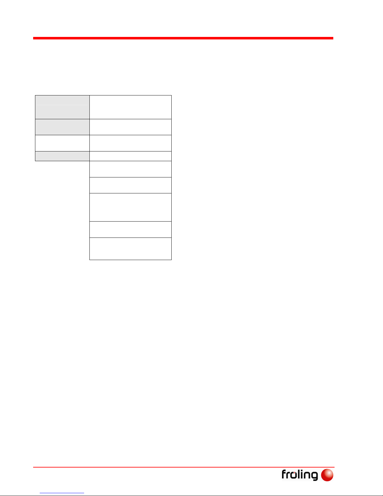
Installers and service technicians
Initial startup
Page 62
B0190806
s
7
Select the system according to the table above, and set on the controls.
When the system has been selected, the display changes to the system
parameters.
The number of the following parameters depends on the system
selected:
System 0 … ←←←←
Bypass pump available
Yes, if there is a bypass pump for return feed lift
No, if a Thermovar valve or a mixer is used for the return
feed lift.
System 1 … X
Storage temp. mid. av.
You can insert a sensor into the storage mid to optimise
the storage layering.
:
DHW control available
Yes, if DHW is available.
No, for hot water heat exchanger.
System 15 …
Oil boiler blocking off No locks the oil boiler when using a common chimney.
Switch value
Oil boiler switch valve: separates the oil boiler
hydraulically from the storage tank.
DHW priority
All heating circuits are switched off during DHW tank
loading.
Solar element
For controlling the temperature difference of a solar panel
system with element. This is carried out via heating
circuit control 1 or 3 (mixer heating circuit 1 or 3 is not
possible).
Heating circuit 1,2,3,4
No, if the heating circuit control is used for “solar
element”.
Remote control 1,2,3,4
A remote control is available as an option for each
heating circuit. If you are using a console RBG 3100 also
set parameter to “yes”.
7.4.4 Checks before first heating up
Heating system
Check that there is sufficient water in the heating system.
Page 35, Checking the system pressure
Check that the heating system is completely vented
Check if the relevant safety devices are available and working
correctly
Page 13, 2.4 Safety Devices
Check that there is sufficient air supply and venting
Page 10, 2.3.3 Ventilating the Boiler Room

Installers and service technicians
Initial startup
Fröling Heizkessel- und Behälterbau Ges.m.b.H, Industriestraße 12, A-4710 Grieskirchen, Austria Page 63
Tel +43 (0) 7248 606-0 Fax +43 (0) 7248 606-600 info@froeling.com www.froeling.com
B0190806
7
Drives
Check that drives and servomotors are working
Check the operating speed of the induced draught fan when the
insulating door is closed
under the limit it must operate at 35 - 40%
Adjust using the “MIN Speed” parameter
Check that the door contact switch is working correctly
When the insulating door is open the induced draught fan runs at
100% speed.
Sensors
Check the sensor shown below in the digital input menu:
Sensor Layout Description
Door contact A 0 ... door closed, switch activated
A 1 ... door open, switch not activated
Set the switch point so that the induced
draught fan operates when the
insulating door is open.
Jam sensor Gravity shaft level sensor (opener):
A 0 ... Sensor covered
A 1 ... Sensor not covered
Jam sensor (closer):
A 0 ... Sensor not covered
A 1 ... Sensor covered
If only screw discharge is used, this
input is used for “Gravity shaft level
sensor”.
The jam sensor is used for suction
systems with screw discharge and is
mounted at the suction piece.
The setting is the same as sensor
“Level MAX”.
Setting sensor “Max level”
Max level Max level (opener):
A 0 ... Sensor covered
A 1 ... Sensor not covered
Set sensor “Max level”
Combustion
chamber excess
pressure monitor
A 0 ... fault, monitor has been triggered
A 1 ... Combustion chamber pressure OK
Used as opener contact. If the cable is
unplugged from the sensor, the
“Pressure monitor comb chamb” error
message is displayed.
Key switch (for
screw discharge
only)
Not displayed in menu When this is activated, the “Key switch
engaged” error message is shown.

Installers and service technicians
Initial startup
Page 64
B0190806
s
7
Setting sensor “Level Max”
In delivery configuration, the factory settings of
the sensor are secured with a seal.
Changes to the settings should only be carried out
by qualified technicians.
The monitoring LED (1) should only illuminate
when identifying materials!
If the monitoring LED is constantly lit, the
sensitivity is set too high!
Reduce the sensitivity by turning the
adjusting screw (2) to the left
If the monitoring LED does not react when
pellets are being fed in, the sensitivity is set
too low!
Increase the sensitivity of the adjusting
screw by turning to the right
7.4.5 Feeding fuel into the combustion chamber
Before the initial setup there are no pellets in the stoker and discharge
screw. With the “Manual fuel” parameter, pellets are fed into the
combustion chamber.
MANUAL FUEL ON←←←← If the first pellets are visible in the combustion bowl,
set the “Manual fuel” parameter back to “OFF”.
CAUTION: Placing too many pellets in the combustion bowl
can increase the danger of flash fires!
Combustion bowl correctly
filled
Too many pellets in the
combustion bowl
1
2

Installers and service technicians
Initial startup
Fröling Heizkessel- und Behälterbau Ges.m.b.H, Industriestraße 12, A-4710 Grieskirchen, Austria Page 65
Tel +43 (0) 7248 606-0 Fax +43 (0) 7248 606-600 info@froeling.com www.froeling.com
B0190806
7
NOTE for Uno/Eco/Komfort universal suction systems and bag silo
systems:
To fill the suction unit container set the “Fill” parameter in the “Manual
operation” menu to “ON”. The suction system starts and the suction unit
container is filled with fuel until the switch point of the level sensor is
reached.
NOTE for screw suction systems, underground tank (external
discharge):
To fill the suction unit container, set the “Start of automatic filling” in
the “Outfeed” menu to one minute after the current time. This starts the
suction system a minute later and the suction unit container is filled with
fuel until the switch point of the level sensor is reached. After filling,
reset the parameters to the desired time.
7.4.6 Setting parameters
After starting the boiler with the key, “Winter operation” mode is set
according to factory settings.
For other modes see 4.2.1 Modes
You need to check and if necessary adjust the following parameter:
Heating curve Radiator or floor heating
Minimum flue gas
temperature
The value should be adjusted for chimneys without
tiles or a stainless steel pipe.
Mode
See 4.2.1 Modes
Induced draught offset Settings are made by the service technician using
an analytical device
The other parameters are factory set in such a way that in most cases
optimal operation is possible without making further changes to the
parameters.
The following parameters, however, can/should be adjusted as desired
by the customer:
- Target boiler temperature
- Storage times
- DHW tank times
- Solar parameters
- Reduction programs
- Heating circuits 1 - 4
- Start of automatic filling (for suction systems)
- Boiler times (only for transitional operation)

Installers and service technicians
Parameter list - Lambdatronic P 3100
Page 66
B0190806
s
7
7.5 Lambdatronic P 3100 parameter list
7.5.1 Menu overview
Pressing the
ENTER
key once takes you from the basic readout to the first
menu level, where the following menu items can be selected:
SET
Page 67, 7.5.2 Settings menu
ERROR DISPLAY
Page 39, 6 Troubleshooting
ERROR LIST
Page 74, 7.5.3 Error list menu
MANUAL OPERATION
Page 75, 7.5.4 Manual operation menu
MANUAL DIGI. OUT
Page 75, 7.5.5 Manual digi.menu OUT
MANUAL ANAL. OUT
Page 76, 7.5.6 Manual anal. menu OUT
MANUAL DIGI. IN
Page 76, 7.5.7 Manual digi.menu IN
SYSTEM SELECTION
Page 60, 7.4.3 Setting system type
Parameters with a grey background can be accessed
by the CUSTOMER (without code).
Parameters in bold are for HEATING ENGINEERS (with code),
Parameters in italics are for SERVICE PERSONNEL (with code).
Untrained operators may enter incorrect settings!
Incorrectly set parameters at “Installer” and “Service” level can
cause serious problems with boiler functioning!

Installers and service technicians
Parameter list - Lambdatronic P 3100
Fröling Heizkessel- und Behälterbau Ges.m.b.H, Industriestraße 12, A-4710 Grieskirchen, Austria Page 67
Tel +43 (0) 7248 606-0 Fax +43 (0) 7248 606-600 info@froeling.com www.froeling.com
B0190806
7
7.5.2 Settings menu
Boiler temp. ... ←←←←
Set boiler temperature 80° ←←←←
The boiler temperature is regulated to this temperature
Shut down over
set temp.+ 5° ←←←←
If the boiler temperature exceeds the target value by
this parameter value, it is shut down. The boiler will
start up again below the target temperature.
Shut down over
max. temp.+ 3°
←
If the boiler temperature exceeds the maximum
temperature (90°) by this parameter value, it is shut
down. The heating circuit, store loading pumps and
DHW tank pumps will also begin to run to cool the
boiler. The boiler will start up again below the target
temperature.
Pumps start at 65° ←←←← The pumps are released at this boiler temperature.
(Hysteresis 2°)
Minimal return
feed temp. 60°
←
The bypass pump is released below this return feed
temperature.
Min spd return
lift pump 45%←←←←
Adjusts the minimum speed to the relevant pump type.
Mixer Ty 240s←←←← For return feed lift with mixer: mixer runtime, depends
on mixer type (> 150s)
Storage tank ... ←←←←
Storage temp. heat circ.
launch 30°←←←←
This is the minimum value for launching the heating
circuit in combination with a storage tank. (applies to
sensor 1 in conjunction with storage tank)
Residual heat use N←←←←
This function can only be used in conjunction with a
bypass pump/return feed mixer.
The residual heat is dissipated from the boiler as the
return feed lift is ignored.
Storage up min temp 60°←←←←
Below this temperature the upper store must drop, so
that the boiler can be started within the store loading
times (in transitional operation).
Boiler storage
mid temp. dif. 5°←←←←
If the option “Storage mid. av.” has been selected, the
boiler controls attempt to keep the temperature of the
“Storage mi.” sensor at the “Boiler target temperature”
minus the temperature difference set here by
regulating the speed of the storage pump = boundary
layer loading.
Storage low =
boiler temp - 10°←←←←
The storage is considered to be loaded when the
“Storage lo. temperature” has reached the boiler
temperature minus the set value.Boiler switches off
Storage pump
min spd 45%←←←←
Adjusts the minimum speed to the pump type.
Note: always set the pump switch to the highest power
level.

Installers and service technicians
Parameter list - Lambdatronic P 3100
Page 68
B0190806
s
7
DHW tank ... ←←←←
Desired DHW tank
temperature 55°←←←←
When the specified temperature is reached in the DHW
tank, the DHW tank loading pump switches off.
Desired DHW tank 2
temperature 55°←←←←
When the specified temperature is reached in DHW
tank 2, DHW tank loading pump 2 switches off.
Recharge when
HWT below 45°C←←←←
Reloading of the DHW tank is authorised when the
DHW tank temperature is below this level.
Recharge when
HWT 2 below 45°C←←←←
Reloading of the DHW tank is authorised when the
DHW tank temperature is below this level.
Storage-DHW
temp diff 6°←←←←
When the top storage tank temperature is above the
DHW tank temperature by this value, the DHW tank
pump is released.
Boiler -DHW
temp diff 6°←←←←
Initial value of DHW tank loading with manually fed
systems (firewood boiler). The boiler temperature must
be higher than the DHW tank temperature by this
value so that the DHW tank loading process begins.
Not active for automatically fed pellet systems!
Residual heat use N←←←← This function can only be used in conjunction with a
bypass pump/return feed mixer.
The residual energy is dissipated from the boiler as the
return feed lift is ignored.
Start of the 1st
loading session 05:00←←←←
Start of authorisation for 1st DHW tank loading session
End of the 1st
loading session 08:00←←←←
End of authorisation for 1st DHW tank loading session
Start of the 2nd
loading session 15:00←←←←
Start of authorisation for 2nd DHW tank loading
session
End of the 2nd
loading session 18:00←←←←
End of authorisation for 2nd DHW tank loading session
heat only once / day N←←←← “Yes” stops repeated heating in one day.
Legionella heating 65° Y←←←← The DHW tank is heated to at least 65°C once a week
Legionella heating day Mo←←←← Day of the week for Legionella heating.
Charge from temp
diff to boiler 6°←←←←
Initial value of DHW tank loading with manually fed
systems (firewood boiler). The boiler temperature must
be higher than the DHW tank temperature by this
value so that the DHW tank loading process begins.
Not active for manually loaded firewood systems!
Loading temp.
addition 10°←←←←
If the difference between the target boiler temperature
and the target DHW tank temperature is not greater
than this parameter, the target boiler temperature is
raised for the duration of DHW tank loading.
Min rev DHW
pump 45%←←←←
Adjusts the minimum speed to the pump type.
Note: always set the pump to the highest power level.
Only operate the pump power switch when the
appliance is switched off
Caution: Pump must run at this speed! Carry out
function test.

Installers and service technicians
Parameter list - Lambdatronic P 3100
Fröling Heizkessel- und Behälterbau Ges.m.b.H, Industriestraße 12, A-4710 Grieskirchen, Austria Page 69
Tel +43 (0) 7248 606-0 Fax +43 (0) 7248 606-600 info@froeling.com www.froeling.com
B0190806
7
Oil boiler ... ←←←←
Oil boiler-Storage
temp diff 10°←←←←
The minimum temperature difference between the oil
boiler and storage tank which releases the oil boiler
loading pump output.
Oil boiler start
delay 60m←←←←
Delays start of the burner relay if the boiler fails (the
boiler status is off, fault or shut down and the boiler
temp. is 5°C below the target value). In storage mode
the burner relay, however, only comes on when the
storage tank has cooled down. (Top storage temp.
lower than maximum temp. required.)
Oil boiler min.
runtime 5m←←←←
Minimum runtime for the oil boiler
Oil boiler min.
temp. 50°←←←←
Oil boiler minimum temperature for release of oil boiler
loading pump or activation of switch valve.
Solar ... ←←←← Setup Sol Register: 1←←←← System-specific parameter: set as per solar diagrams!
Option for systems
0-9
DHW tank target for
solar l. 65°←←←←
When the specified temperature is reached in the DHW
tank sensor, the DHW tank loading pump switches off.
When using a switch valve, it switches to the heating
element of the storage tank.
Min rev solar pumps 45%←←←← Adjusts the minimum speed to the relevant pump type.
Solar ON diff temp 10°←←←←
The collector loading pump activates when the collector
temperature exceeds the storage or DHW tank
temperature by this value
Solar OFF diff temp 5°←←←←
The collector loading pump switches off when the
collector temperature exceeds the storage or DHW tank
temperature by this value
Max temp storage
low 85°←←←←
Maximum bottom storage tank temperature switches
solar loading pump off (unless the excess temperature
protection for the collector activates (135°)). Only in
conjunction with storage tank.
Solar ... ←←←← Min rev solar pumps 45%←←←← Adjusts the minimum speed to the relevant pump type.
In conjunction with
solar heat
exchanger (systems
12,13,14 and 15)
Coll. ON temp. dif. 10°←←←←
The collector loading pump activates when the collector
temperature exceeds the lower storage or DHW tank
temperature by this value.
Max temp storage
low 85°←←←←
Maximum bottom storage tank temperature switches
solar loading pump off (unless the excess temperature
protection for the collector activates (135°)).
ON Delay storage
pump 600s←
ON and OFF delay for the storage-HE-pump relative to
the collector pump
Storage Solar set 60°← Top storage tank target value for solar loading
Solar return storage
lo diff 16°←
Maximum temperature difference between bottom
storage tank temperature or bottom DHW tank
temperature and collector return feed temperature.

Installers and service technicians
Parameter list - Lambdatronic P 3100
Page 70
B0190806
s
7
Heating times... ←←←←
Heating prog.
1... ←←←←
Heating phase
1 start 06:00
Lowered outside of heating phases.
Only in conjunction with
heating circuit control.
Heating phase
1 end 11:00
Heating phase
2 start 15:00
Heating phase
2 end 23:00
Heating prog. 2...
Heating prog. 3...
Heating prog. 4...
Heating prog. 5...
Heating prog. 6...
Heating prog. 7...
Heating prog. 8...
Heating prog. 9...
Heating prog. 10...
Heating prog. 11...
Heating prog. 12...
Heating prog. 13...
Heating prog. 14...
2 heating phases each,
like heating prog. 1.
You can program up to 14 heating times
each with two heating phases.
These are assigned to the individual days
of the week in the parameter “Heating
circuit 1-4 / weekly program”.
Heating
circuit 1 ... ←←←←
Weekly
program
MoTuWeThFrSaSu
1 1 3 1 1 2 5
Heating time programs 1-14 are assigned
to the days of the week for heating circuit
1.
Heating curve
... ←←←←
Flow temp. At
external –10°C 60°←←←←
Only in conjunction
with heating circuit
control.
Flow temp. at outer
+10°C 40°←←←←
You can adjust the heating curve to the
relevant system in these two work points.
Room temp.
set value 20°←←←←
Target room temperature value during the heating
phase
only with remote control
Room temp.SV reduced
amount 16°←←←←
Target room temperature value during the drawdown
phase
only with remote control
Room temp. contr.
factor (Kp). 6.0←←←←
Influencing factor of room temp. on flow temp. If the
room temp. deviates by 1°C or more, the target value
for the flow temperature resulting from the set heating
curve is corrected by this value.± (only with remote
control)
Flow temperature
reduction of 15°←←←←
The flow temperature is reduced by this value in
drawdown phase.
Ext. temp. heating
limit 18°←←←←
If the external temperature exceeds this heating limit
during the heating phase, the heating circuit pump and
mixer are switched off.
Ex.temp.heatlim.
reduced amount 7°←←←←
If the outside temperature exceeds this heating limit
during the drawdown phase, the heating circuit pump
and mixer are switched off.
Flow temp. max.
value 75°←←←←
Maximum temperature for limiting flow temperature.
(system dependent: floor heating, radiators,..)
Mixer Ty 240s←←←←
Set mixer runtime of heating circuit mixer in use!
Note: do not set mixer time under 150s!

Installers and service technicians
Parameter list - Lambdatronic P 3100
Fröling Heizkessel- und Behälterbau Ges.m.b.H, Industriestraße 12, A-4710 Grieskirchen, Austria Page 71
Tel +43 (0) 7248 606-0 Fax +43 (0) 7248 606-600 info@froeling.com www.froeling.com
B0190806
7
Frost. prot. temp.
(internal) 10°←←←←
If the room temperature or the outfeed temperature is
lower than the set value, the heating circuit pump will
be switched on.
Heating
circuit 2 - 4
Programming as in heating circuit 1
Flue gas
temp. ... ←←←←
Minimum flue gas
temperature 120°←←←←
Minimum target value for the flue gas temperature.
Lowest load point for continuous operation (if this
temperature is not reached, the output will be
increased).
Insulate the connection to the chimney!
Maximum flue gas
temperature 250°←←←←
Minimum target value for the flue gas temperature.
Top load point to ensure adequate efficiency (if this
temperature is exceeded, the output will be reduced).
Min diff boiler flue
gas 15°←←←←
In “Heating” status: if the difference between flue gas
temperature and boiler temperature falls below this
specified value, when the safety time has elapsed, the
controls go to “Fault” status “Safety time elapsed
too low”.
In “Ignition” status: if the difference with the “Ignition
time max” does not exceed the value, the boiler goes
to “Fault”“Ignition attempt failed”
Min. flue g.-flue g.
temp. dif. 5°C
After heating, the flue gas temperature must have
risen by this value compared to the value before the
heating phase, to reach the status “Heating up”.
Flue gas temp.
shut down 80°C←←←←
For emergency firewood operation: if the flue gas
temperature is below the specified value for 30
minutes, the ID fan and supply air fan are switched off.
Safety time 15m←←←←
If during “Heating” status the shutdown conditions
(Boiler-flue gas temp.dif. or Shutdown excess O2) for
this period are not met, the boiler goes to “Insufficient
safety time elapsed” or “Safety time O2 too high”.
Ignition ... ←←←← Feed without ignition 75s←←←←
Boiler in “heating up” status: Filling time for
combustion bowl. After this time has elapsed, the
boiler goes to “pre-heating” status
Factory settings: P2-10: 105s, P2-15: 95s, P2-20/25:
75s
Fan without ignition 70%←
Boiler in “Heating up” status: Speed during the
heating up phase
Ignition on without
feed 120s←
Boiler in “Pre-heating” status: Duration of the preheating phase.
No pellets are fed in.
Fan without feed 45%←
Boiler in “Pre-heating” status: Speed during the preheating phase
Ignition time max 15m←
The boiler changes from “Ignition” status to “Heating”
status within the “Ignition time max” if the flue gas
temperature has reached the required value (“Min.
boiler-flue gas temp. dif.” parameter). Otherwise it
goes to the fault “Ignition attempt failed!”.
Feed during ignition 30%←
Factory settings for pellet slide-in in “Ignition” status:
P2-10/15: 60%, P2-20/25: 30%
Fan during ignition 66%← Fan speed during “Ignition” status
Fan during shutdown 40%← Fan speed during “Shutdown” status

Installers and service technicians
Parameter list - Lambdatronic P 3100
Page 72
B0190806
s
7
Air settings ... ←←←← ID fan MIN 35%
←
Lower control limit; check during initial setup
Start from 0% and test going up in steps of 5%. . Start
level setting through control parameter, → ID fan start
point
Fan MIN 16%← Adjustment to fan in use – do not change setting
Fan MAX 65%←
Fan speed at maximum output
Factory settings: P2-10: 60%, P2-15: 65%, P2-20:
70%, P2-25: 75%
100% output from
Flue gas temp. 100°←←←←
If the flue gas temperature is above the specified
target value, fuel output should reach 100% (upper
point of the start ramp)
Output at flue gas temp.
of 20° 50%←←←←
Output limit (lower point of the start ramp)
Offset for ID fan 0%←←←← The ID fan curve is increased by this value
New induced draft fan Y←←←←
ID fan with rubber buffer → Y
ID fan with spacers → N
Pellets feed ... ←←←←
Feed MAX 70%←
Slide-in at maximum output for systems without
lambda probes; systems with lambda probes are
controlled by the O2 regulator.
STBY. Wait 1 10m← 1. Shutdown pause before the 1st safety slide-in
STBY. Wait 2 20m← 2. Pause between 1st and 2nd safety slide-in
Shutdown slide-in 1s←
Duration of safety slide-ins (for status: Shutdown slidein 1 and 2)
Ash screw Runtime: 5s←←←← Runtime of the ash screw
Ash screw Cycle: 1200←←←←
Ash screw cycle; control of the ash screw depending on
the pellet slide-in.
EOS runtime 20s←←←← Runtime of heat exchanger cleaning
Outfeed ... ←←←←
1. Start time for
automatic filling 15:00←←←←
1. Start time for filling. This is only carried out if the fill
level in the container is under 85%.
Only with suction
discharge unit!
2. Start time for
automatic filling 15:00←←←←
2. Start time for filling. This is also only carried out if
the fill level in the container is under 85%.
Period of screw
cycle 30s←←←←
Discharge screw runtime, minus a pause of 10* sec.
(*Pause time = “Suction unit pre-activation time”)
Preliminary suction 10s← Time before the discharge screw starts
ID fan after shut down 15s←
Time after discharge screw stops.
For sucking the hose clear.
Fill cyclone below: 35%←
Minimum level of day store suction cycle starts when
the level falls below this value.
Note: with underground tanks or bag silos the values
for pre-activation and post-shutdown times should be
set according to the manufacturer’s instructions.

Installers and service technicians
Parameter list - Lambdatronic P 3100
Fröling Heizkessel- und Behälterbau Ges.m.b.H, Industriestraße 12, A-4710 Grieskirchen, Austria Page 73
Tel +43 (0) 7248 606-0 Fax +43 (0) 7248 606-600 info@froeling.com www.froeling.com
B0190806
7
Outfeed ←←←←
1. Start time for
automatic filling 15:00←←←←
1. Start time for filling. This is only carried out if the fill
level in the container is under 85%.
Only for universal
suction systems
2. Start time for
automatic filling 15:00←←←←
2. Start time for filling. This is also only carried out if
the fill level in the container is under 85%.
Fill cyclone below: 35%←
Minimum level of day store suction cycle starts when
the level falls below this value.
Boiler times ... ←←←←
Start 1. Storage
tank load 05:00←←←←
Only effective in
transitional
operation!
End 1. Storage
tank load 10:00←←←←
Start 2. Storage
tank load 17:00←←←←
Start 2. Storage
tank load 22:00←←←←
For systems with storage tank in transitional
operation:
The boiler is switched on if the temperature falls
below the “Store up. min. temp.” during these time
windows.
Note: Ideally set start 00:00 to end 24:00
Start 1. heating
period 05:00←←←←
End 1. heating
period 08:00←←←←
Start 2. heating
period 17:00←←←←
End 2. heating
period 21:00←←←←
For systems without storage tank in transitional
operation!
The boiler is activated within these time windows.
CAUTION!
DHW tank loading times must be within the time
window of the boiler times.
Start EOS 1 08:00←←←←
Start time 1 for heat exchanger cleaning. The boiler
must have operated for at least 2 hours since the last
cleaning.
Start EOS 2 15:00←←←←
Start time 2 for heat exchanger cleaning. The boiler
must have operated for at least 2 hours since the last
cleaning.
Only with Lambda control:
Lambda values...
←←←←
Residual O2
content target 9.0%←←←←
Target value for residual oxygen content.
Residual O2
shut down 19.0%←←←←
If the residual oxygen content in heating status goes
above this specified value, after the safety time, the
boiler goes to “Fault” status, error message: “Safety
time O2 too high” see chapter 6 Troubleshooting
No feed below: O2 4.5%←←←← No pellets are slid in below this oxygen value.
O2 control max 130%← Specific settings for O2 controller – do not change
Factor for O2 controller 1.50← Specific settings for O2 controller – do not change
Control par. ...
←
Start level draft fan 0.0%←
Start level for ID fan; to correct the direct control curve
of the induced draught fan.
Specific setting for ID fan – do not change

Installers and service technicians
Parameter list - Lambdatronic P 3100
Page 74
B0190806
s
7
Mode:
Winter operation
You can select from:
Winter operation
Summer operation
Transitional operation
Firewood operation (EMERGENCY OPERATION)
Cleaning
RBG 3100
Alloc.: 14
Console 3100: possible allocation combinations
Normal: Allocation and control of this heating circuit only
Master: Allocation to respective heating circuit, control of
other heating circuits also possible
Other combinations have no function
Normal Master
HC1 1 11
HC2 2 12
HC3 3 13
HC4 4 14
No allocation 0
Set day Set the current date.
Set time Set the current time.
Restore factory
settings ←←←←
Restores the default settings on the control.
It takes a few seconds for the factory settings to be restored.
Clear error list ←←←← Deletes all the data saved in the error list.
7.5.3 Error list menu
Up to 25 warnings/errors already eliminated and the respective times
are stored here.
Warning 12/07/01
005 clr. 23:17:24
clr ... cleared:
Error no. 005 was eliminated at this time.
Warning 12/07/01
005 ack. 23:16:23
ack ... acknowledged:
Error no. 005 was acknowledged at this time.
Warning 12/07/01
005 occ. 23:15:18
Remote control 2 error
occ ... occurred:
Error no. 005 occurred at this time.
To display the respective error text press the enter key, e.g.: “Remote
control 2 faulty”.
A list of possible error messages is contained in the chapter on
troubleshooting.

Installers and service technicians
Parameter list - Lambdatronic P 3100
Fröling Heizkessel- und Behälterbau Ges.m.b.H, Industriestraße 12, A-4710 Grieskirchen, Austria Page 75
Tel +43 (0) 7248 606-0 Fax +43 (0) 7248 606-600 info@froeling.com www.froeling.com
B0190806
7
7.5.4 Manual operation menu
Used for manual fuel feed to the burner and manual operation of heat
exchanger motor and ash screw.
MANUAL FUEL ON←←←← Manual fuel feed to burner
ASH SCREW OFF←←←← Ash screw ON/OFF
EOS OFF←←←← Heat exchanger cleaning ON/OFF
FILLING OFF←←←←
After activating the parameter, the container is filled
with fuel, regardless of fill level, until the function is
turned off or the switch point of the level sensors is
reached. When the level sensor reaches its limit
value, the fill level value is set to 100%.
Caution: Parameter only for universal suction
systems Uno/Eco/Komfort and bag silo units!
7.5.5 Manual digi.menu OUT
Used to test the digital outputs and is intended only for heating
engineers. The display depends on the configuration.
HC1 pump A 0←←←← Heating circuit 2-4 same, if present
HC1-Mi open A 0←←←← Heating circuit 2-4 same, if present
HC1-Mi closed A 0←←←← Heating circuit 2-4 same, if present
Oil boiler
contact A 0←←←←
Burner relay: for burner start or burner release
Only present if system with oil burner has been
selected.
HC0 pump A 0←←←← Only possible if system does not have oil burner.
Lambd Heat 0 A 0←←←← Lambda probe heating
Ignition A 0←←←← Ignition fan
Suction A 0←←←← Only with suction discharge unit!
Ash screw A 0←←←← Ash screw
Relays for
Fault message A 0←←←←
Fault message relays for external warning device
(e.g.: buzzer, house control system)
Heat exchanger
motor A 0←←←←
Heat exchanger cleaning
Switch power
supply A 0←←←←
Only with universal suction system; Servomotor
supply system
Probe 1
Active A 0←←←←
Only with universal suction system; control probe 1
Probe 2
Active A 0←←←←
Only with universal suction system; control probe 2
Probe 3
Active A 0←←←←
Only with universal suction system; control probe 3
A 0... Automatic, OFF A... AUTOMATIC
A 1... Automatic, OFF 0... Manual OFF
1... Manual ON

Installers and service technicians
Parameter list - Lambdatronic P 3100
Page 76
B0190806
s
7
7.5.6 Manual anal. menu OUT
Used to test the digital outputs and is intended only for heating
engineers. The display depends on the configuration.
ID fan A 0%←←←←
Storage tank LP
A 0%
Storage tank loading pump
DHW LP A 0%←←←← DHW tank loading pump
Pump 1 A 0%←←←←
Pump 2 A 0%←←←←
Pump 3 A 0%←←←←
Comb air fan
A 0%
Supply air fan
Stoker A 0%
←
Function check is also possible in “Manual control” menu
Discharge
screw A 0%
←
Function check is also possible in “Manual control” menu
HCP 1 A 0%
←
Collector pump for solar systems (if available)
A 0%... Automatic, OFF
A 1%-100%... Automatic, corresponding value ON
A... AUTOMATIC
0%... Manual OFF
1%-100%... Manual with corresponding value ON
7.5.7 Manual digi.menu IN
Used to test the digital inputs and is intended only for heating
engineers. The display depends on the configuration.
Door sensor A 0
←
Limit thermostat
emergency off A 1
←
Safety temperature limiter / EMERGENCY STOP
Jam sensor A 0
←
“Jam sensor” for suction feed “Gravity shaft level sensor”
for screw discharge
Level MIN A 0
←
Input not covered
Level MAX A 1
←
Only for suction feed: Maximum for day store ends suction
cycles.
Com.Ch. exc.
press. A 1
←
Combustion chamber excess pressure monitor: “Opener”
Ext. req. A 0
←
For external heat requirements, e.g. from a house control
system input “S6 boiler release” in pellet module
A 0… Automatic, OFF A… AUTOMATIC
A 1... Automatic, ON 0... Manual OFF
1… Manual ON

Appendix
Manufacturer’s guarantee conditions
Fröling Heizkessel- und Behälterbau Ges.m.b.H, Industriestraße 12, A-4710 Grieskirchen, Austria Page 77
Tel +43 (0) 7248 606-0 Fax +43 (0) 7248 606-600 info@froeling.com www.froeling.com
B0190806
8
8 Appendix
8.1 Guarantee conditions
Our sale and delivery conditions generally apply. These conditions have
been made available to customers, and customers have been made
aware of them at the time of order completion.
You can also find the guarantee conditions in the enclosed guarantee
certificate.
8.2 Manufacturer address
FRÖLING
Heizkessel- und Behälterbau GesmbH
Industriestraße 12
A-4710 Grieskirchen
AUSTRIA
TEL +43 (0)7248 606 0
FAX +43 (0)7248 606 600
E-MAIL info@froeling.com
INTERNET www.froeling.com

Appendix
Declaration of Conformity
Page 78
B0190806
s
8
8.3 Declaration of Conformity
EU DECLARATION OF CONFORMITY
Product: Pellet boilers
Types:
Pellet boiler P2-10,
P2-15,
P2-20,
P2-25
Pellet boiler
Pellet boiler
Pellet boiler
EU Directives:
Legal Regulations for Machinery
Legal Regulations for Electrical Equipment:
Low Voltage Directive
Electromagnetic Compatibility (EMC) Directive
Applied harmonized standards:
Boilers for Solid Fuels up to 300 kW
Requirements, Testing, and Designation
Welding Quality Specifications
National technical guidelines:
Boilers; Rules for testing heating systems
Technical directives on fire protection/prevention
Automatic wood burning system
We hereby certify that the series production version of the product designated above
meets the directives, guidelines and standards specified.
Grieskirchen, 15.02.2006
Quality Assurance
Technical Services
89/392/EEC
73/23/EEC
89/336/EEC

Your Notes
Fröling Heizkessel- und Behälterbau Ges.m.b.H, Industriestraße 12, A-4710 Grieskirchen, Austria Page 79
Tel +43 (0) 7248 606-0 Fax +43 (0) 7248 606-600 info@froeling.com www.froeling.com
B0190806
9
9 Your Notes

Menu overview
Lambdatronic P 3100
B0190806
s
Winter Operation
Heating
Boiler temp.
Flue gas temp.
ID Fan
Residual O2
Storage.up.
Storage.mi.
Storage.low
DHW tank temp.
Coll. temp.
Oil boiler
Ext. temp.
Flow temp.
Day
Time
Version
Runtime
User name
customer
Set
Error display
Error list
Manual operation
Man. Digi. OUT
Man. Digi. IN
Man. Anal. OUT
System selection
Ash screw Heat
exchanger filling
Boiler type…
System …
Code:
Service
Installer
Customer
Diagram - heating curve
External temperature
Flow temperature
Example of floor heating
Example of radiators
NOTE:
Number and display of parameters depend
on the system selected!
Areas with a grey background are visible
to the customer!
Boiler temp.
Storage tank
DHW tank
Solar
Heating times
Heating circuit 1
Heating circuit 2
Heating circuit 3
Heating circuit 4
Air parameters
Pellets feed
Outfeeder
Boiler times
(transitional operation)
Mode:
Winter operation
RBG 3100
alloc.: 11
Set day
Set time
Clear error
list
Set boiler temperature
Store temp. Heating circuit release
Store up. min. temp.
Set DHW tank temp.
Recharge when HWT below
Start 1. load
End 1. load
Start 2. load
End 2. load
Setup Sol Register
DHW tank target for solar loading
Heating prog. 1
Heating prog. 2
Heating prog. 14
Weekly prog.
Heating curve
Room temp. set value
Chamber control factor
Flow temp. Reduction
Ex.temp.heatlim. reduced amount
Flow temperature max. value
Mixer type
Frost prot.temp. (inside)
Room temp. set value Drawdown mode
Fan MAX
Slide-in MAX
1. Start time for autom. fillung
2. Start time for autom. fillung
Start 1. heating period
End 1. heating period
Start 2. heating period
End 2. heating period
Winter operation
Summer operation
Transitional operation
Firewood operation
Cleaning
Start 1. heating period
End 1. heating period
Start 2. heating period
End 2. heating period
Mo Tu We Th Fr Sa Su
1 1 1 1 4 9 3
Flow temp. At external -10 °C
Flow temp. At external +10 °C
same as heating
circuit 1
same as heating
prog. 1
1
 Loading...