

Page 1
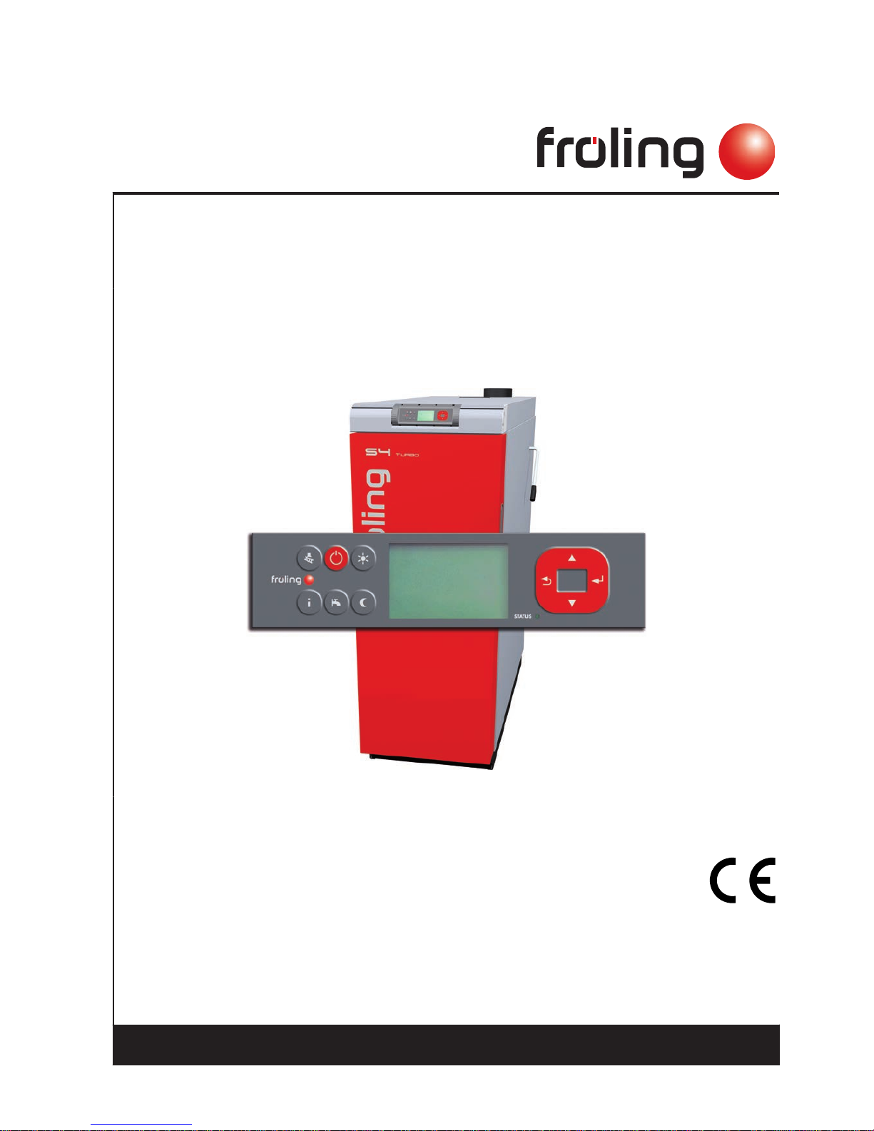
Operating Instructions
Boiler controller Lambdatronic S 3200
Version 50.04 - Build 05.09
Translation of the original German operating instructions for technicians and operators
Read and follow the instructions and safety information!
Technical changes, typographical errors and omissions reserved!
B0361214_en | Edition 21/07/2014
Froling GesmbH | A-4710 Grieskirchen, Industriestraße 12 | www.froeling.com
Page 2

Contents
1 General 5
1.1 About these instructions 5
1.2 Safety information 5
2 Electrical connection and wiring 6
2.1 Core module and connection options 6
2.1.1 Board view 6
Connection instructions
7
2.1.2 Mains connection 8
2.1.3 Connecting the flue gas sensor 8
2.1.4 Combination with oil burner 9
2.1.5 Valve for flue gas condenser connection 9
2.1.6 Connecting the remote control 10
2.1.7 Connecting a high efficiency pump to the core module 11
2.2 Expansion modules 12
2.2.1 Heating circuit module 12
2.2.2 Hydraulic module 13
Connecting an isolating valve
14
Connecting a high efficiency pump to the hydraulic module
15
2.2.3 Return mixer module 16
2.2.4 Ignition expansion 18
2.2.5 Connecting the bus cable 18
2.2.6 Connect the patch cable to the bus plug 19
2.2.7 Setting end jumpers 19
2.2.8 Setting the module address 20
2.3 Connection diagrams according to pump types 20
3 Overview of the basic functions 22
3.1 Control keys and display 22
3.1.1 Navigation keys 22
3.1.2 Status LED 22
3.1.3 Graphic display 23
3.2 Function keys 24
3.2.1 Standby key 24
3.2.2 Service program key 24
Chimney sweeper function
24
3.2.3 Info key 24
3.2.4 DHW tank program key 25
3.2.5 Party program key 26
3.2.6 Setback program key 26
4 Operation 27
4.1 Before switching on for the first time 27
4.1.1 Controller check 27
4.1.2 Check on the connected units 27
4.1.3 System Check 27
4.2 Initial startup 28
4.2.1 Changing the operating level 28
4.2.2 Setting the system type 29
4.2.3 Before heating up for the first time 32
Contents
2 Froling GesmbH | A-4710 Grieskirchen, Industriestraße 12 | www.froeling.com
Page 3

Drives
32
4.3 Heating up the boiler 32
4.3.1 Heating up 33
4.3.2 Heating up with automatic ignition 33
4.4 Operating statuses 34
4.5 Setting parameters 35
4.6 Setting times 35
4.6.1 Deleting a time window 36
5 Menu overview and parameters 37
5.1 Menu - Heating 38
5.1.1 Status displays for the heating circuits 39
5.1.2 Temperature settings for the heating circuit 39
5.1.3 Heating times of the heating circuits 40
5.1.4 Service parameters of the heating circuits 41
5.1.5 Service parameters for heating up program 42
Heating up programs
42
5.1.6 General settings 43
5.2 Menu - Water 43
5.2.1 Status displays for the DHW tank 44
5.2.2 Temperature settings of the DHW tank 44
5.2.3 Heating times of the DHW tank 45
5.2.4 Service parameters of the DHW tank 45
5.3 Menu - Solar 46
5.3.1 Status displays for the solar system 47
5.3.2 Temperature settings for the solar system 48
5.3.3 Service parameters of the solar system 49
5.3.4 Solar heat meter 51
5.4 Menu - Storage tank 51
5.4.1 Status displays of the storage tank 52
5.4.2 Temperature settings for the storage tank 52
5.4.3 Service parameters of the storage tank 54
5.5 Menu - Boiler 55
5.5.1 Status displays for the boiler 56
5.5.2 Temperature settings for the boiler 56
5.5.3 Service parameters of the boiler 57
5.5.4 General settings 57
5.6 Menu - Boiler 2 57
5.6.1 Status displays for the secondary boiler 58
5.6.2 Temperature settings of the secondary boiler 58
5.6.3 Service parameters for secondary boiler 59
5.7 Menu - Ignition 59
5.8 Menu - Network pump 60
5.8.1 Status display of the network pump 61
5.8.2 Network pump temperature settings 61
5.8.3 Service parameters for the network pump 62
5.9 Menu – Diff. control 62
5.9.1 Status displays for the diff. control 63
5.9.2 Temperature settings for the diff. control 63
5.9.3 Service parameters for the diff. control 64
5.10 Menu - Circulation pump 64
5.10.1 Status display for the circulation pump 65
Contents
Operating Instructions Lambdatronic S 3200 | B0361214_en 3
Page 4

5.10.2 Temperature settings for the circulation pump 65
5.10.3 Time settings for the circulation pump 66
5.10.4 Service parameters of the circulation pump 66
5.11 Menu - Manual 66
5.11.1 Digital outputs 67
5.11.2 Analogue outputs 67
5.11.3 Digital inputs 68
5.12 Menu - System 68
5.12.1 Settings 69
Setting parameters – Boiler temperature
69
Adjustable parameters – Flue gas
70
Adjustable parameters – Ignition
71
Adjustable parameters – Air settings
72
Adjustable parameters – Lambda values
72
Adjustable parameters - Lambda probe - LSM11 Lambda probe
73
Adjustable parameters – Lambda values – Broadband probe
73
General settings
75
5.12.2 Current values 75
5.12.3 Error list 76
5.12.4 Parameters for sensors and pumps 77
5.12.5 Display operating rights 77
5.12.6 Display allocations 78
5.12.7 Basic display parameters 79
5.12.8 Changing languages 80
5.12.9 Changing the date 80
5.12.10 Changing the time 80
5.12.11 Standard settings 80
5.12.12 Current user level 80
5.12.13 System type 81
5.13 PWM / 0 - 10V settings 81
6 Troubleshooting 83
6.1 Procedure for fault messages 83
7 Setting protocol 85
Contents
4 Froling GesmbH | A-4710 Grieskirchen, Industriestraße 12 | www.froeling.com
Page 5
1 General
1.1 About these instructions
Please read and follow the operating instructions, in particular the safety information
contained therein. Keep them available next to the boiler.
These operating instructions contain important information about operation, electrical
connection and troubleshooting for the
Lambdatronic S 3200 control.
NOTICE
The values given in the parameter lists are examples, and
should not be used as standard values!
The constant further development of our products means that there may be minor dif‐
ferences from the pictures and content. If you discover any errors, please let us know.
1.2 Safety information
DANGER
When working on electrical components:
Risk of electrocution!
When work is carried out on electrical components:
❒ Only have work carried out by a qualified electrician
❒ Observe the applicable standards and regulations
➥ Work must not be carried out on electrical components by unauthorised
people
WARNING
When touching hot surfaces:
Severe burns are possible on hot surfaces and the flue gas pipe!
When work is carried out on the boiler:
❒ Shut down the boiler in a controlled way (operating status "Off") and allow it to
cool down
❒ Protective gloves must generally be worn for work on the boiler, and it should
only be operated using the handles provided
❒ Insulate the flue pipes or simply avoid touching them during operation.
The information on safety, standards and guidelines in assembly and operating in‐
structions for the boiler should also be observed.
General
1
About these instructions
Operating Instructions Lambdatronic S 3200 | B0361214_en 5
Page 6
2 Electrical connection and wiring
2.1 Core module and connection options
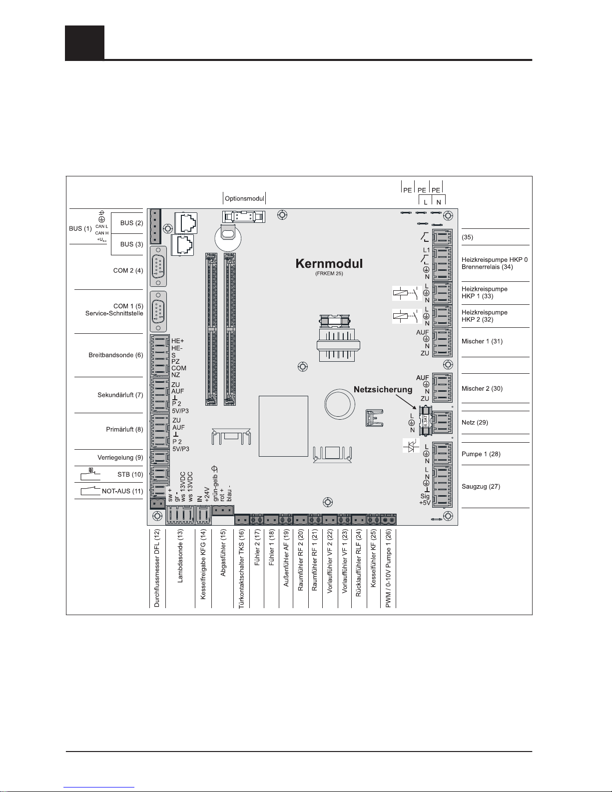
2.1.1 Board view
2
Electrical connection and wiring
Core module and connection options
6 Froling GesmbH | A-4710 Grieskirchen, Industriestraße 12 | www.froeling.com
Page 7
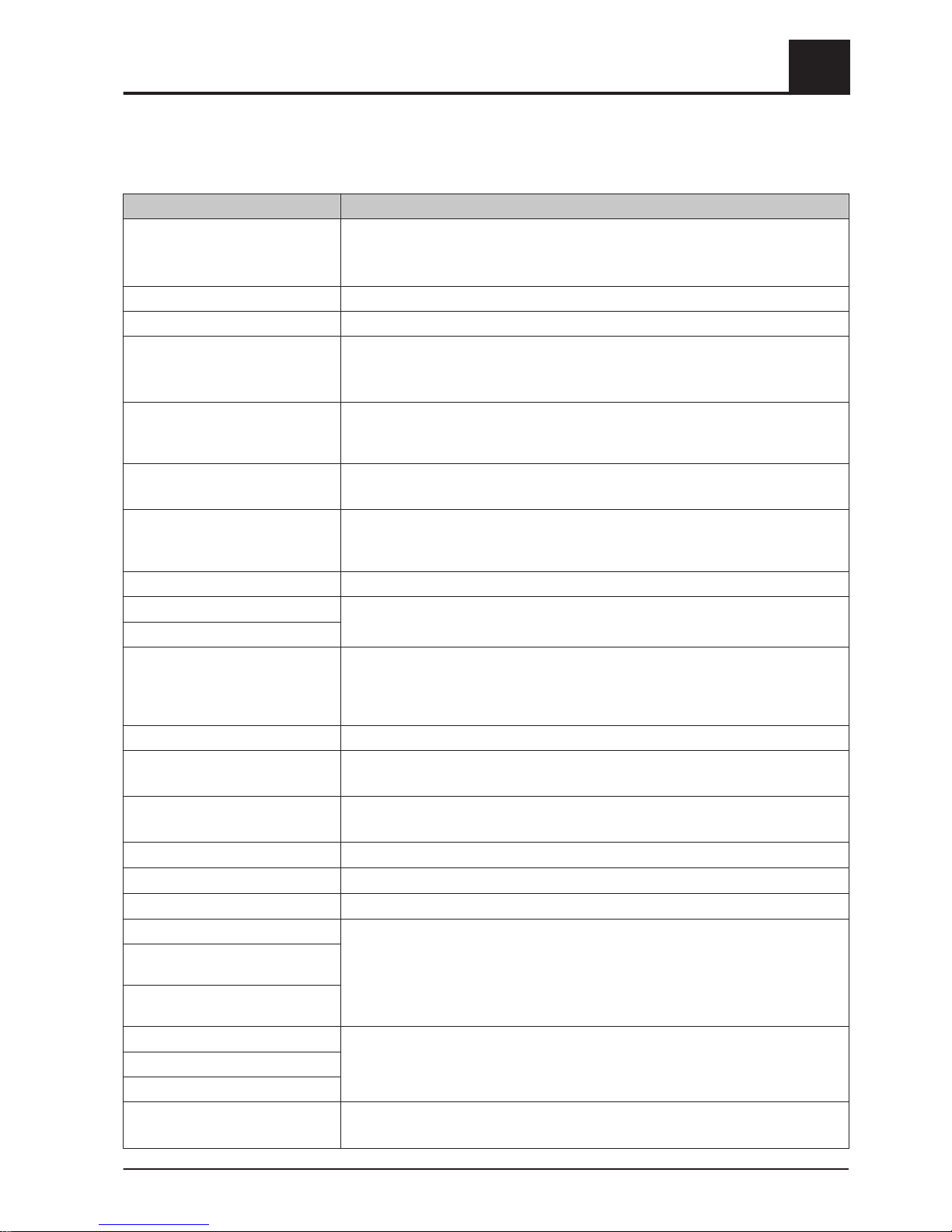
Connection instructions
Port Cable dimensions / Specifications / Information
Bus (1) Port with cable – LIYCY paired 2x2x0.5;
⇨ See "Connecting the bus cable" [page
18]
❒ Warning! CAN L and CAN H must not be connected to +U
BUS
!
Bus (2) Patch cable CAT 5 RJ45 SFTP 1:1 configuration
Bus (3) Patch cable CAT 5 RJ45 SFTP 1:1 configuration, boiler display port
COM 2 (4) Null modem cable 9-pin SUB-D;
❒
Port can be used as a MODBUS interface
General Settings
COM 1 (5) Null modem cable 9-pin SUB-D;
❒
Service interface for installing new boiler software or port for the visualisation
software
Broadband probe (6)
Connection cable1) 5 x 0.75 mm
2
❒
Connection of a BOSCH or NTK broadband Lambda probe
Secondary air (7)
Connection cable1) 5 x 0.75 mm²
❒
When using the S1 Turbo firewood boiler, the air flap must be connected a the
“Secondary air” connection port
Primary air (8)
Connection cable1) 5 x 0.75 mm²
Latch (9)
Connection cable1) 2 x 0.75 mm
2
High-limit thermostat - STL (10)
EMERGENCY STOP (11)
Connection cable1) 2 x 0.75 mm
2
❒
Warning! Do not connect the emergency off/emergency stop switch to the power
supply cable of the boiler. The switch must be a N/C switch and it must be linked
to the 24V safety chain of the STL at this terminal.
Flowmeter FLM (12)
Connection cable1) 2 x 0.75 mm
2
Lambda probe (13)
Connection cable1) 4 x 0.75 mm²
❒
LSM11 Lambda probe connection
Boiler release (14)
Connection cable1) 2 x 0.75 mm
2
❒
Warning! The connection must be a floating connection.
Flue gas temperature sensor (15)
Connection cable1) 3 x 0.75 mm
2
Door switch DCS (16)
Connection cable1) 2 x 0.75 mm
2
Sensor 2/1 (17/18)
Connection cable1) 2 x 0.75 mm
2
Outside temperature sensor (19)
Connection cable1) 2 x 0.75 mm2,shielded from 25m cable length
Room temperature sensor 2/1
(20/21)
Flow temperature sensor 2/1
(22/23)
Return sensor RTS (24)
Connection cable1) 2 x 0.75 mm
2
Boiler sensor BS (25)
PDM / 0-10V Pump 1 (26)
Induced draught (27)
Connection cable1) 3 x 1.5 mm2, power supply
Connection cable1) 3 x 0.75 mm2, analysis of current speed
Electrical connection and wiring
2
Core module and connection options
Operating Instructions Lambdatronic S 3200 | B0361214_en 7
Page 8
Port Cable dimensions / Specifications / Information
Pump 1 on core module (28)
Connection cable1) 3 x 1.5 mm2, max. 1.5A / 280W / 230V
Mains (29)
Connection cable 1) 3 x 1.5 mm2; fused with 16A (provided by the customer)
Mixing valve 2/1 (30/31)
Connection cable
1)
4 x 0.75 mm2, max. 0.15A / 230V
Heating circuit pump 2/1 (32/33)
Connection cable1) 3 x 1.5 mm2, max. 2.5A / 500W
Heating circuit pump HCP 0 / burn‐
er relay (34)
Connection cable1) 3 x 1.5 mm2, max. 3A / 600VA
(35)
Connection cable1) 2 x 0.75mm
2
⇨ See "Valve for flue gas condenser connection" [page
9]
1.YMM as per ÖVE-K41-5 or H05VV-F as per DIN VDE 0881-5
2.1.2 Mains connection
Connect the power supply at the "Mains connection" plug
❒
Flexible sheathed cable must be used for the wiring; this must be of the correct
size to comply with applicable regional standards and regulations.
❒ The power supply line (mains connection) must be fitted with a 16A fuse by the
customer. If a safety overload switch is used it should be a type with 16A.
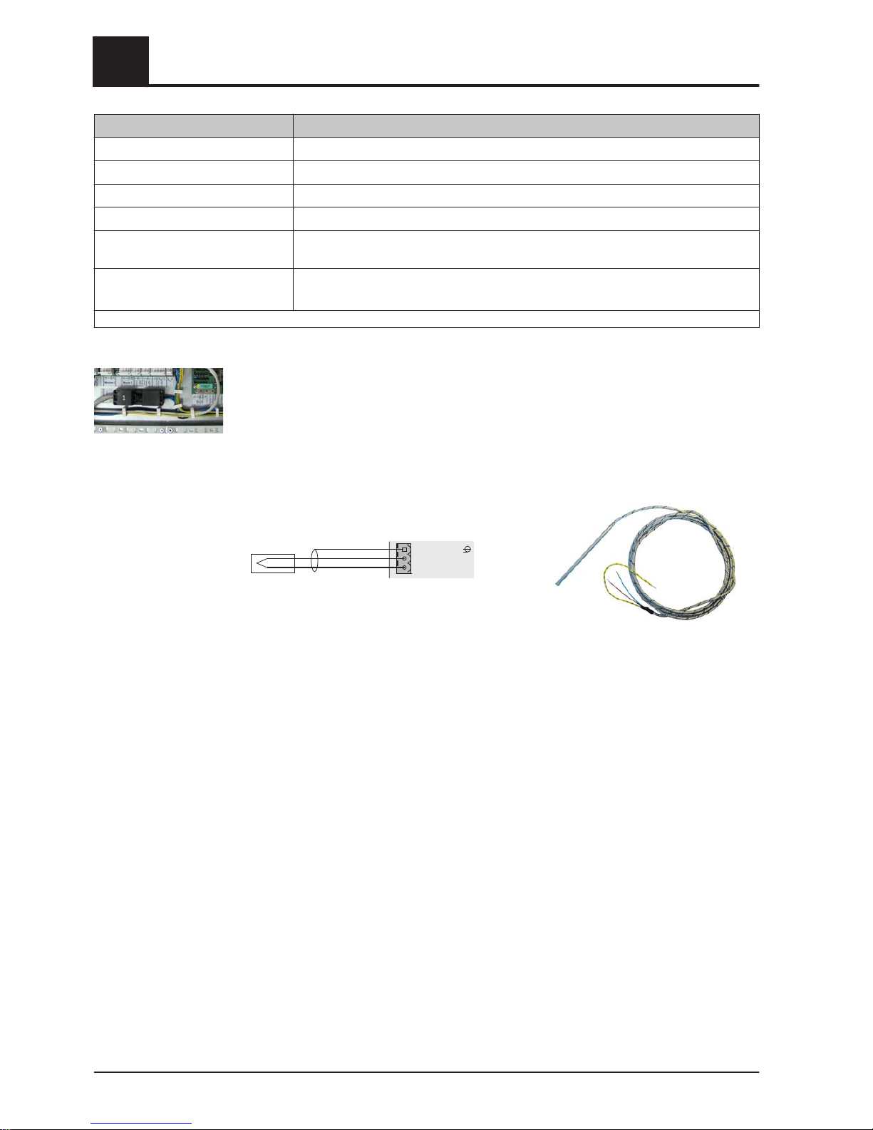
2.1.3 Connecting the flue gas sensor
green-yellow
red+
blue-
Coremodule
2
Electrical connection and wiring
Core module and connection options
8 Froling GesmbH | A-4710 Grieskirchen, Industriestraße 12 | www.froeling.com
Page 9
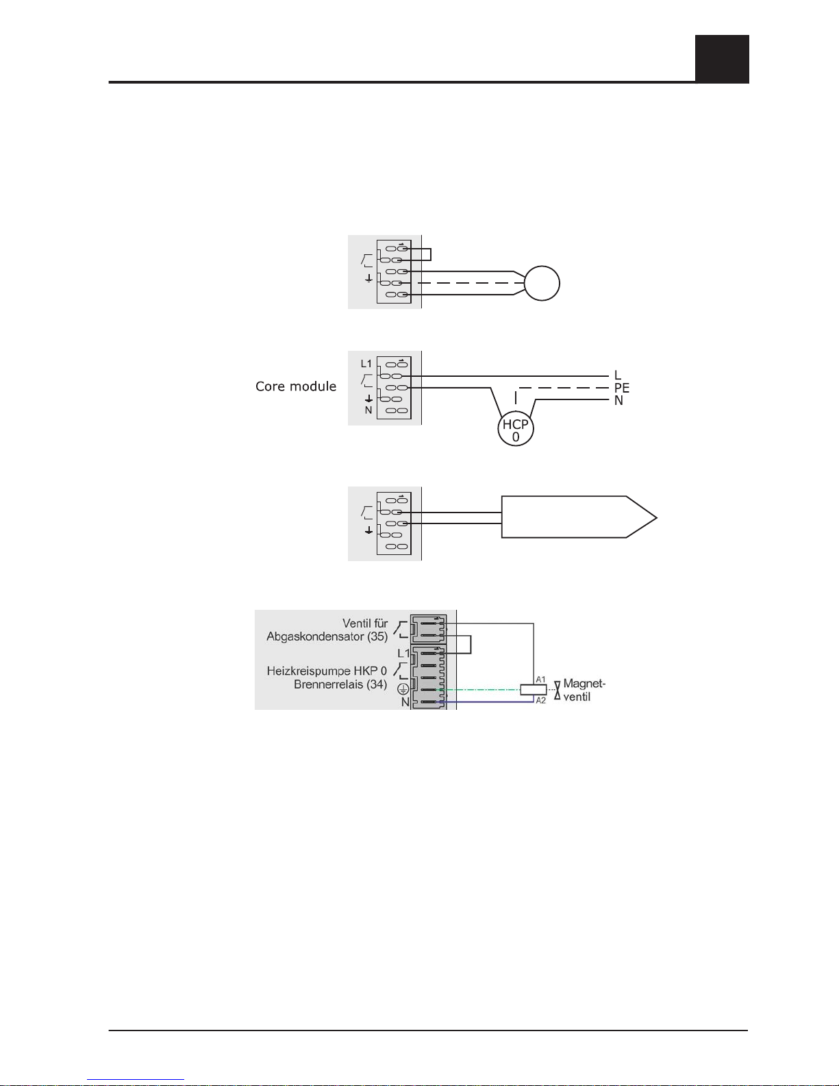
2.1.4 Combination with oil burner
The connection "Heating circuit pump 0" can be used for heating circuit pump 0 or as
burner relays depending on the system setting.
Connecting a HCP 0 up to max. 2 Ampere:
Coremodule
L1
N
HCP
0
Connecting a HCP 0 up to max. 5 Ampere:
Connection as burner relays:
Coremodule
L1
N
Tooilboilercontrol:
floatingcontactforburner
release
2.1.5 Valve for flue gas condenser connection
Electrical connection and wiring
2
Core module and connection options
Operating Instructions Lambdatronic S 3200 | B0361214_en 9
Page 10
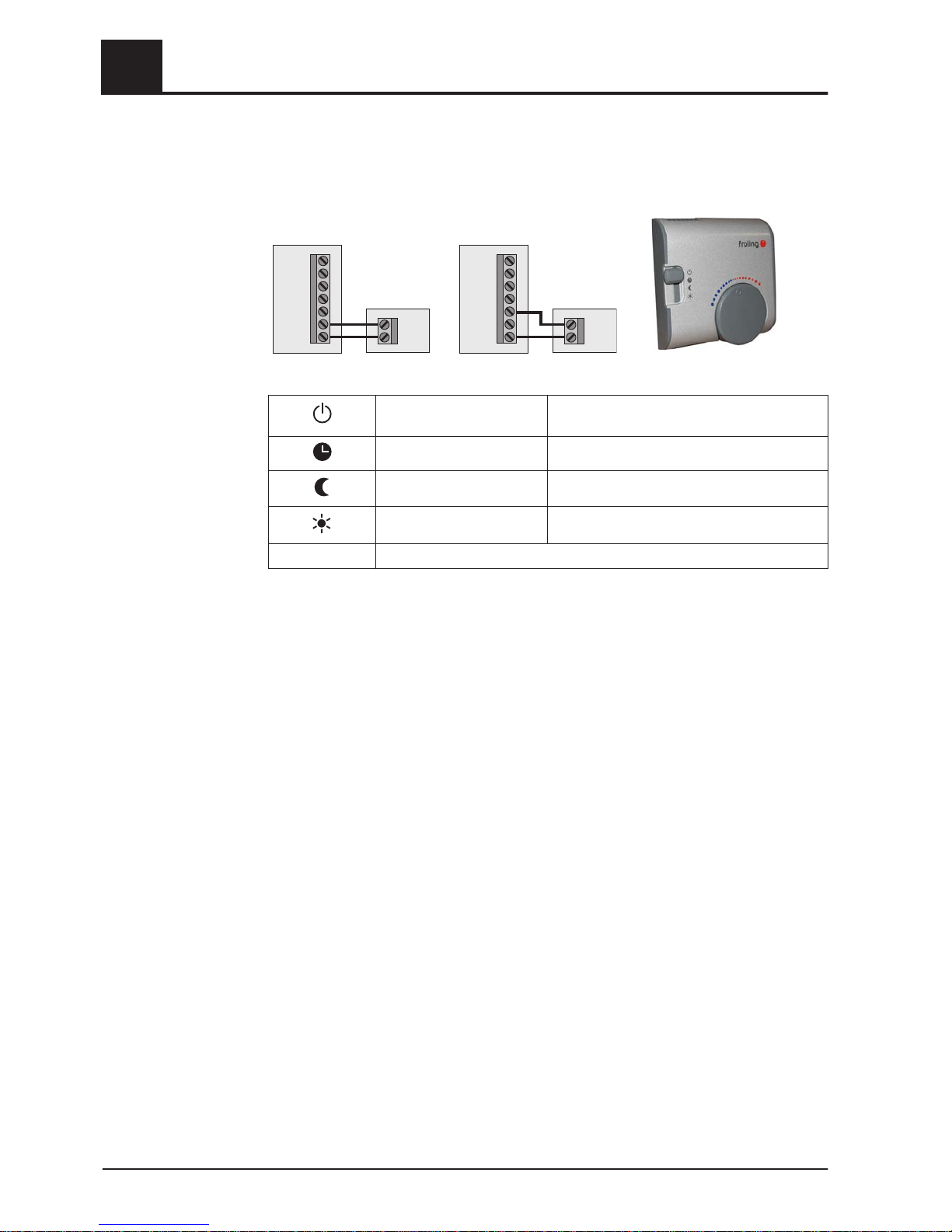
2.1.6 Connecting the remote control
A room temperature sensor is included in the remote control, which sends the current
room temperature to the control.
affecting room:
AUS
UHR
NACHT
TAG
FV
RFFV
COM
Raumfühler FRA
RF 1/2
Kernmodul S/P/H 3200
not affecting room:
AUS
UHR
NACHT
TAG
FV
RFFV
COM
Raumfühler FRA
RF 1/2
Kernmodul S/P/H 3200
Switch settings:
Switched-off Heating circuit deactivated, only frost protec‐
tion!
Automatic mode Heating phases according to setback program
Setback mode Ignores the heating phases
Override circuit Ignores the setback
Handwheel… Allows you to adjust the temperature by +/- 3°C
IMPORTANT! See assembly instructions/functional description for room temperature
sensor FRA
2
Electrical connection and wiring
Core module and connection options
10 Froling GesmbH | A-4710 Grieskirchen, Industriestraße 12 | www.froeling.com
Page 11
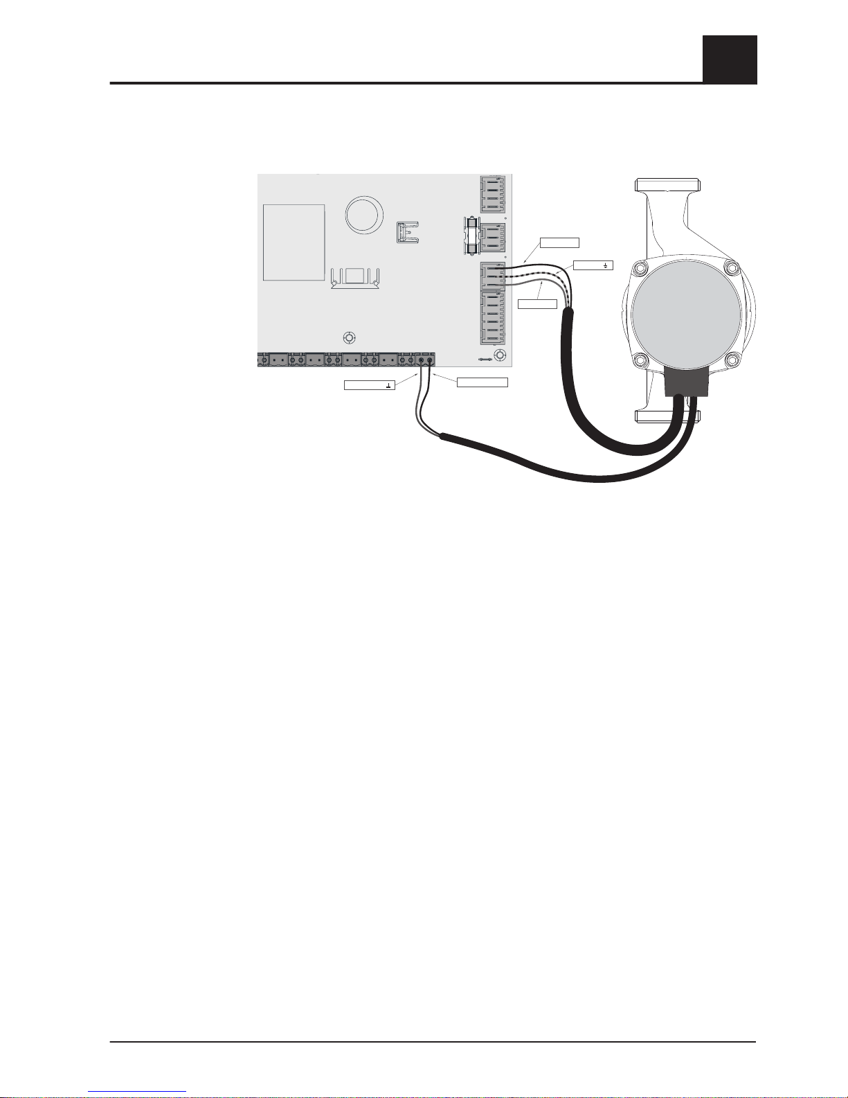
2.1.7 Connecting a high efficiency pump to the core module
Wire the high efficiency pump as shown in the connection diagram below:
KERNMODUL
FRKEM25
PDM / 0-10V (+)
PDM / 0-10V ( )
Pump 1 (L)
Pump 1 ( )
Pump 1 (N)
❒ Connect the power supply for the high efficiency pump to output "Pump 1" of the
core module
❒
Connect the PWM cable of the high efficiency pump to the corresponding port
“PWM / 0-10V"
➥ Make sure that the cables are configured correctly (polarity) in accordance with
the connection diagram of the pump!
Important! When using a Froling pump assembly:
⇨ See "Connection diagrams according to pump types" [page 20]
Electrical connection and wiring
2
Core module and connection options
Operating Instructions Lambdatronic S 3200 | B0361214_en 11
Page 12
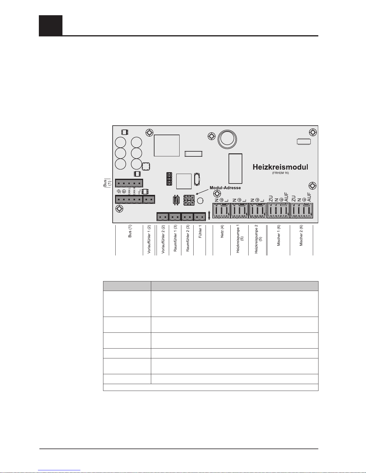
2.2 Expansion modules
2.2.1 Heating circuit module
Two heating circuits can be controlled as standard with the core module.
The heating circuit module boards must be used to expand the heating circuit control.
Eight heating circuit modules (addresses 0 to 7) can be added, and the module ad‐
dress must be set correctly.
⇨ See "Setting the module address" [page
20]
Connection instructions
Port Cable dimensions / Specifications / Information
Bus (1) Port with cable – LIYCY paired 2x2x0.5;
⇨ See "Connecting the bus cable" [page
18]
❒ Warning! CAN L and CAN H must not be connected to +U
BUS
!
Flow temperature
sensor 1/2 (2)
Connection cable1) 2 x 0.75mm
2
Room temperature
sensor 1/2 (3)
Connection cable1) 2 x 0.75mm2, shielded from 25m cable length
Mains (4)
Connection cable1) 3 x 1.5mm2, fuse 10A
Heating circuit
pump 1/2 (5)
Connection cable1) 3 x 1.5mm2, max. 2.5A / 230V / 500W
Mixing valve 1/2 (6)
Connection cable
1)
4 x 0.75mm2, max. 0.15A / 230V
1.YMM as per ÖVE-K41-5 or H05VV-F as per DIN VDE 0881-5
2
Electrical connection and wiring
Expansion modules
12 Froling GesmbH | A-4710 Grieskirchen, Industriestraße 12 | www.froeling.com
Page 13
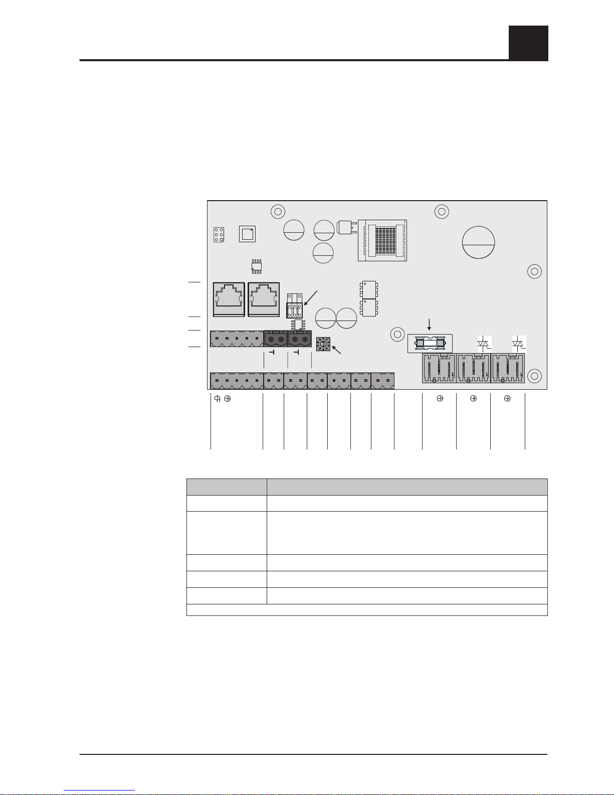
2.2.2 Hydraulic module
The hydraulic module makes the connections of sensors and pumps available for the
hydraulic components of the system (storage tank, DHW tank etc.).
A hydraulic module is included in the delivery as standard (address 0). A further seven
modules (addresses 1 to 7) can be retrofitted.
You must ensure that the module address is given correctly.
⇨ See "Setting the module address" [page
20]
AO-
P1
AO-
P2
6,3AT
Hydraulikmodul
(FRHYU 21)
Bus (2)
Fühler 1 (3)
Fühler 5 (7)
Netz (9)
Pumpe 2 (11)
Fühler 2 (4)
Fühler 4 (6)
Fühler 3 (5)
Pumpe 1 (10)
Fühler 6 (8)
Bus
(2)
2x Bus
(1)
Modul-Adresse
End-Jumper
Netzsicherung
CAN L
CAN H
+U
Bus
N
L
N
L
N
L
+
+
Connection instructions
Port Cable dimensions / Specifications / Information
2 x Bus (1) Patch cable CAT 5 RJ45 SFTP 1:1 configuration
Bus (2) Connection with cable - LIYCY paired 2x2x0.5;
⇨ See "Connecting the bus cable" [page
18]
❒ Important! CAN L and CAN H must not be connected to +U
BUS
!
Sensors 1 – 6 (3-8)
Connection cable1) 2 x 0.75mm2, shielded from 25m cable length
Mains (9)
Connection cable1) 3 x 1.5mm2, fuse 10A
Pump 1/2 (10/11)
Connection cable1) 3 x 1.5mm2, max. 1.5A / 230V / 280W
1.YMM as per ÖVE-K41-5 or H05VV-F as per DIN VDE 0881-5
Electrical connection and wiring
2
Expansion modules
Operating Instructions Lambdatronic S 3200 | B0361214_en 13
Page 14
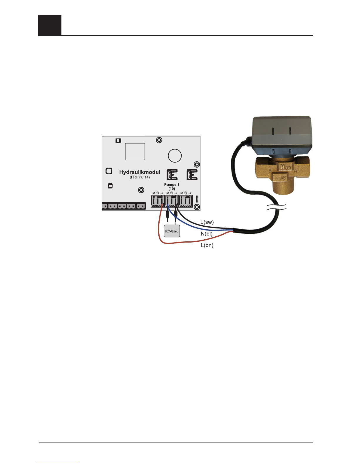
Connecting an isolating valve
If an isolating valve is connected to a speed-controlled pump outlet, an RC element
must be used.
Furthermore, the minimum speed for the pump outlet in use must be set to 100% in
the boiler control system.
Connection example:
The outer cable L(bn) should be connected to the outer cable of the respective mains
supply of the module or to the core module, HCP0/burner relay output at pin “LV”.
2
Electrical connection and wiring
Expansion modules
14 Froling GesmbH | A-4710 Grieskirchen, Industriestraße 12 | www.froeling.com
Page 15
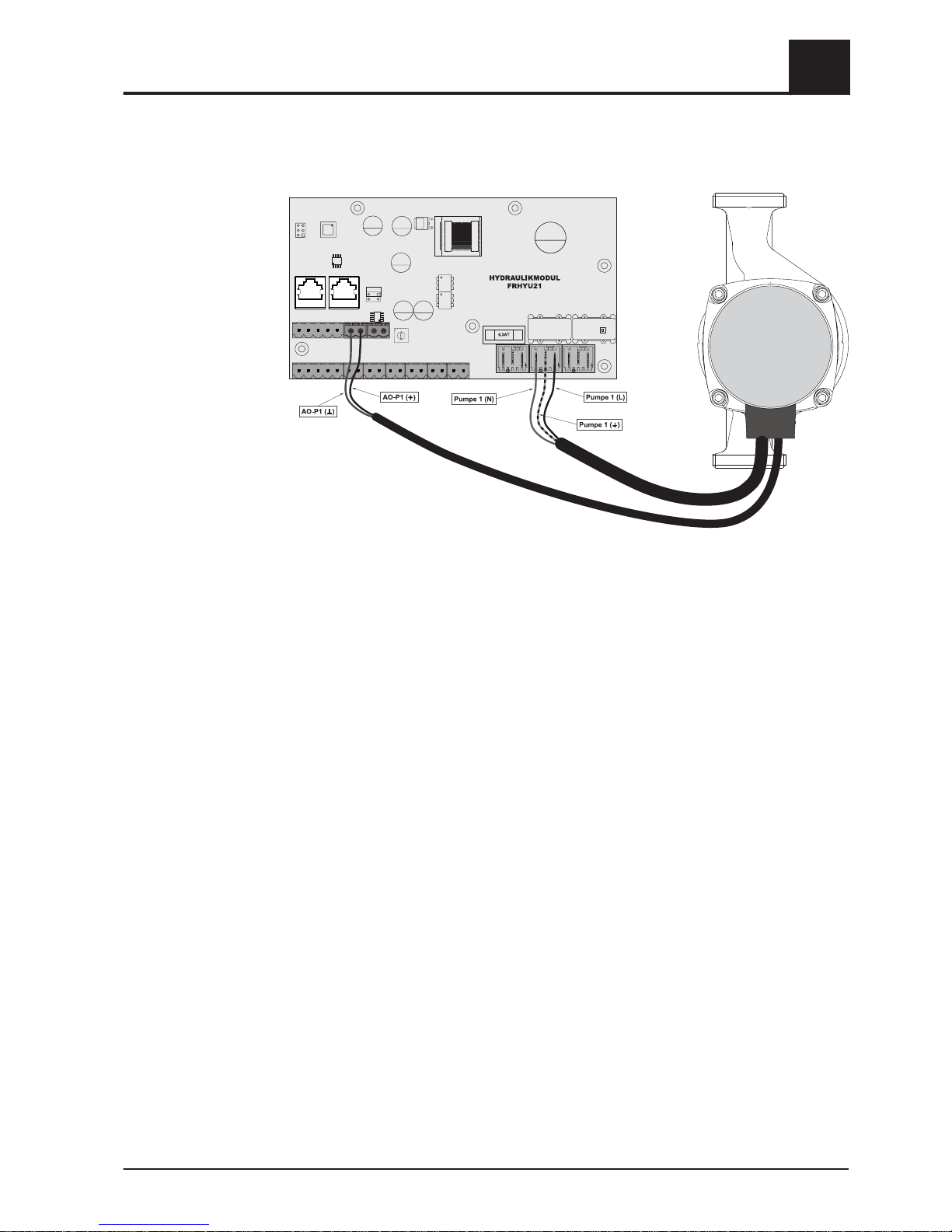
Connecting a high efficiency pump to the hydraulic module
Wire the high efficiency pump as shown in the connection diagram below:
❒ Connect the power supply for the high efficiency pump to output "Pump 1" or
"Pump 2" of the hydraulic module
❒
Connect the PWM cables of the high efficiency pump to the corresponding port
"AO-P1" or "AO-P2"
➥ Make sure that the cables are configured correctly (polarity) in accordance with
the connection diagram of the pump!
IMPORTANT! When using a Froling pump assembly:
⇨ See "Connection diagrams according to pump types" [page 20]
Electrical connection and wiring
2
Expansion modules
Operating Instructions Lambdatronic S 3200 | B0361214_en 15
Page 16
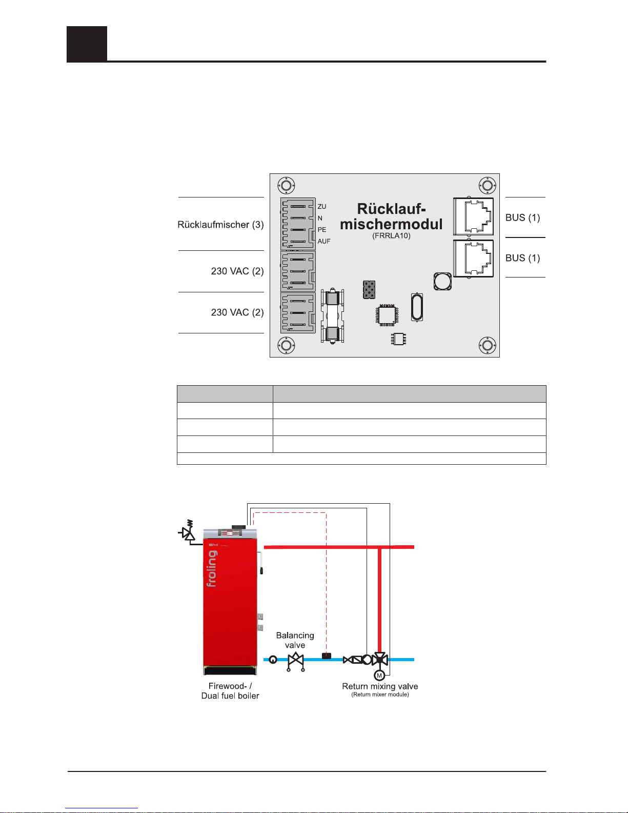
2.2.3 Return mixer module
The return mixer module provides the connection for a return mixer. The relevant sen‐
sor is the return sensor on the core module. If this module is used, the “Return
flow mixer through external module” parameter must be set to “YES”.
⇨ See "Setting the system type" [page 29]
Connection instructions
Port Cable dimensions / Specifications / Information
Bus (1) Connection with enclosed patch cable 0.5m
2 x mains (2)
Connection cable1) 3 x 1.5mm2,
Return mixer (3)
Connection cable
1)
4 x 0.75mm2, max. 0.15A / 230V
1.YMM as per ÖVE-K41-5 or H05VV-F as per DIN VDE 0881-5
Connection example
2
Electrical connection and wiring
Expansion modules
16 Froling GesmbH | A-4710 Grieskirchen, Industriestraße 12 | www.froeling.com
Page 17
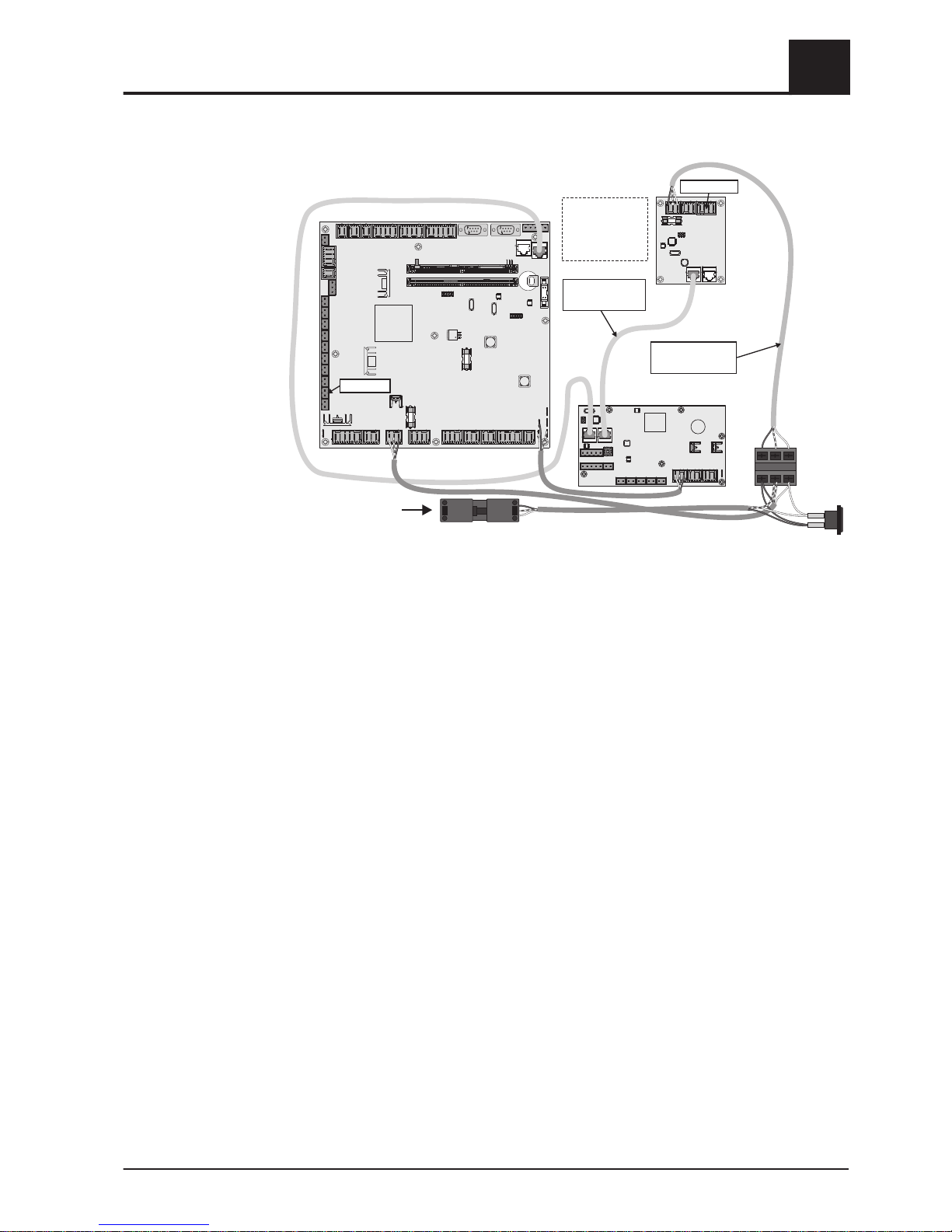
Connection diagram
Hydraulicmodule
(FRHYU14)
Coremodule
(FRKEM22)
Returnmixer
module
(FRRLA10)
Mainswitch
Plug
Mains
Connectreturnmixer
moduleandhydraulic
modulewithbuscable
Usedeliveredmains
cableforconnection
toterminalblock.
Ignitionmodule
(optional)
Returnmixer
Returnsensor
Electrical connection and wiring
2
Expansion modules
Operating Instructions Lambdatronic S 3200 | B0361214_en 17
Page 18
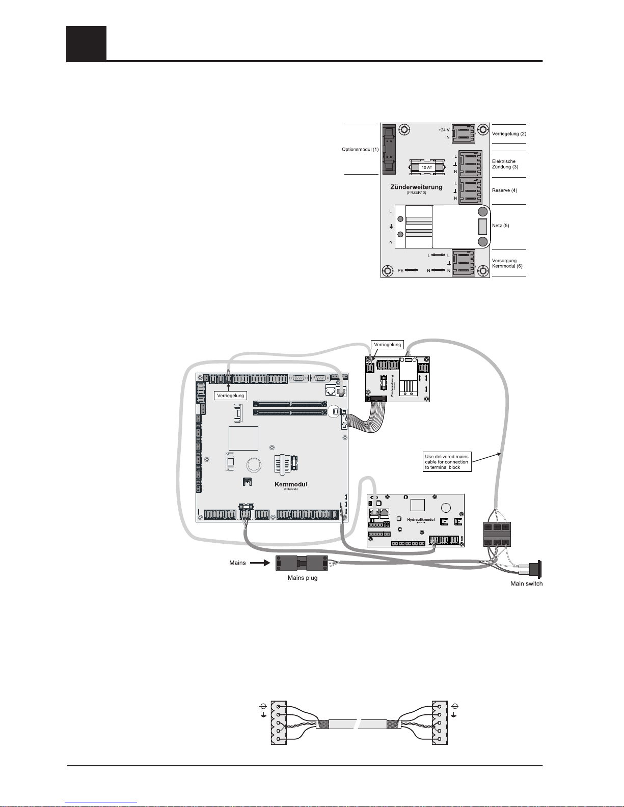
2.2.4 Ignition expansion
The ignition expansion makes the con‐
nection for an electrical ignition fan avail‐
able and makes it possible for the boiler
to be heated up automatically.
Connection diagram
2.2.5 Connecting the bus cable
For the bus connections between the individual modules, cable type
LIYCY paired 2x2x0.5 should be used. The connection to the 5-pin plugs should be
carried out according to the following diagram:
+U
BU
S
CANH
CANL
+U
BU
S
CANH
CANL
Braidedshield
White
Green
Y
ellow
Brown
Braidedshield
White
Green
Yellow
Brown
2
Electrical connection and wiring
Expansion modules
18 Froling GesmbH | A-4710 Grieskirchen, Industriestraße 12 | www.froeling.com
Page 19
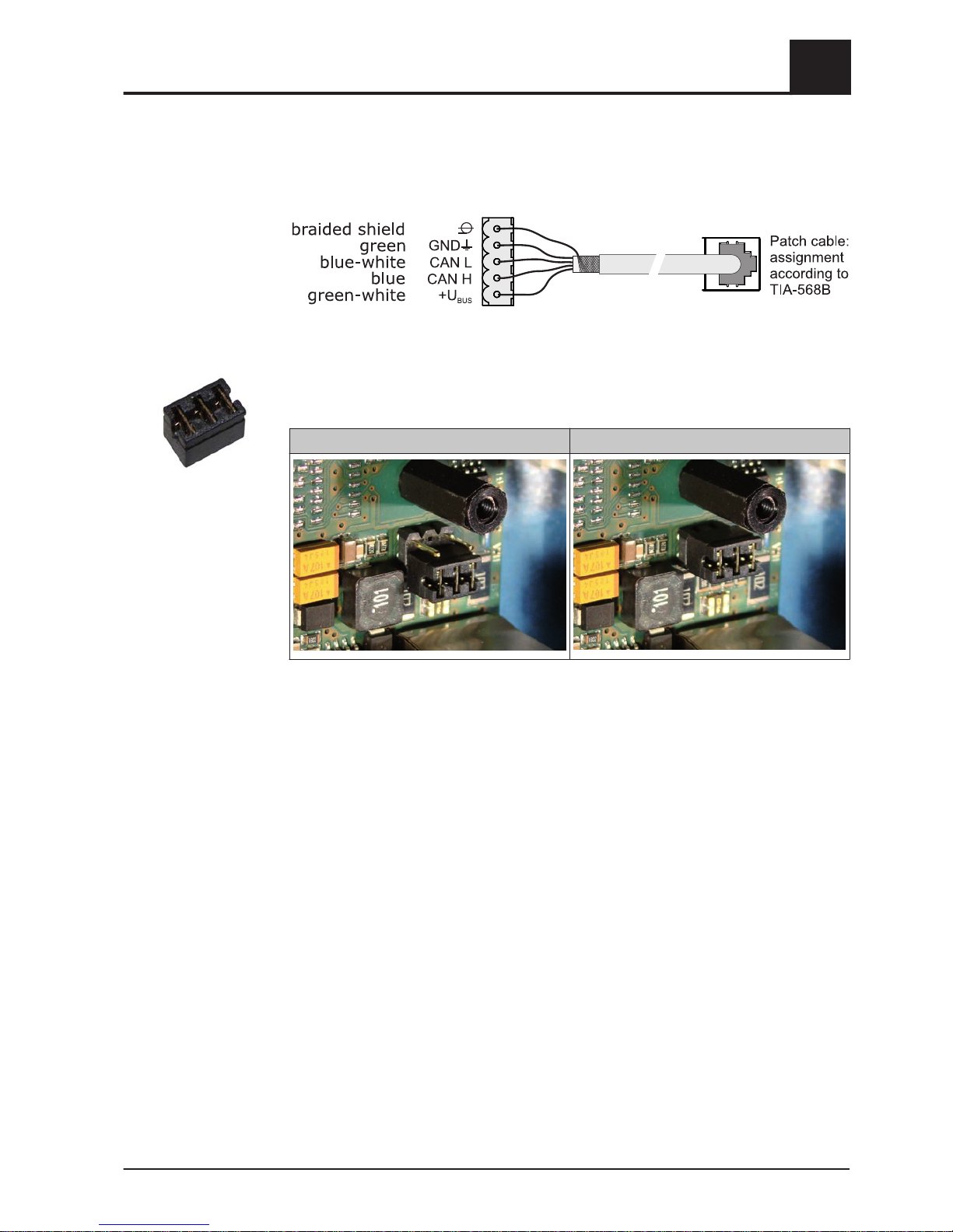
2.2.6 Connect the patch cable to the bus plug
To connect a patch cable to a RJ45 bushing and a 5-pin plug, follow the connection
diagram below:
2.2.7 Setting end jumpers
To ensure smooth running of the bus system, the jumper must be placed on the last
module.
End jumper not set End jumper set
If the contacts at the base of the end jumper are not bridged (image left), it is referred
to as “not set". In this case there is no bus termination. If the contacts are closed (im‐
age right), the end jumper is set and the bus connection is terminated.
Electrical connection and wiring
2
Expansion modules
Operating Instructions Lambdatronic S 3200 | B0361214_en 19
Page 20
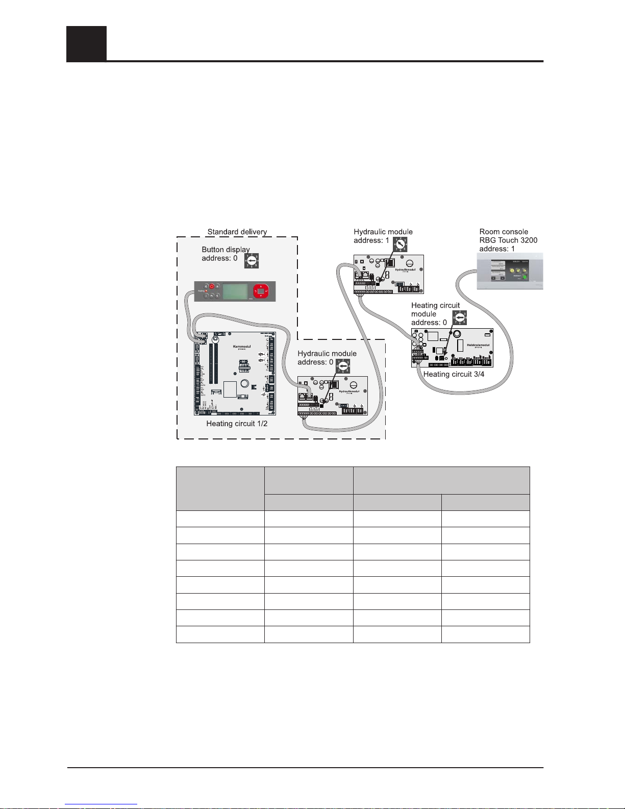
2.2.8 Setting the module address
For hydraulic modules or heating circuit modules it is necessary to set the required or‐
der with the module addresses. The first board of a module type should always have
the address 0, so that the standard hydraulic systems set do not have to be subse‐
quently configured. For further module types ascending module addresses (address 1
- 7) are set.
A hydraulic module with address 0 is included in standard delivery. If a second hy‐
draulic module is also installed, address 1 is set.
Module
address set
Heating circuit mod‐
ule
Hydraulic module
Heating circuit Sensor Pump
0 03 – 04 0.1 – 0.6 0.1 – 0.2
1 05 – 06 1.1 – 1.6 1.1 – 1.2
2 07 – 08 2.1 – 2.6 2.1 – 2.2
3 09 – 10 3.1 – 3.6 3.1 – 3.2
4 11 – 12 4.1 – 4.6 4.1 – 4.2
5 13 – 14 5.1 – 5.6 5.1 – 5.2
6 15 – 16 6.1 – 6.6 6.1 – 6.2
7 17 - 18 7.1 – 7.7 7.1 – 7.2
2
Electrical connection and wiring
Expansion modules
20 Froling GesmbH | A-4710 Grieskirchen, Industriestraße 12 | www.froeling.com
Page 21
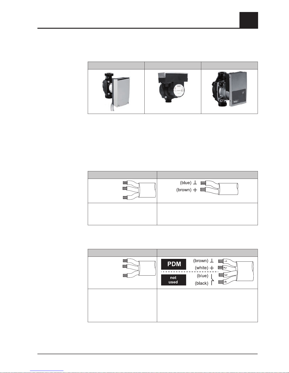
2.3 Connection diagrams according to pump types
Three different pump types are used in all depending on the pump assembly used:
WILO Stratos Para WILO Stratos TEC WILO Yonos Para
Either a 2-pin control cable (WILO Stratos TEC, WILO Yonos Para) or a 4-pin control
cable (WILO Stratos Para) is used for the connection depending on the pump type.
Please follow the connection instructions below for the wiring depending on the pump
type used:
Pump type with 2-pin control cable
Power supply 2-pin control cable
(brown) L
(blue) N
(yellow-green) PE
Wire the power supply to the pump
outlet on the board
Connect the control cable to the board’s PWM output,
making sure that the polarity is correct:
- blue wire to earth
- brown wire to plus
Pump type with 4-pin control cable
Power supply 4-pin control cable
(brown) L
(blue) N
(yellow-green) PE
Wire the power supply to the pump
outlet on the board
Connect the control cable to the board’s PWM output,
making sure that the polarity is correct:
- brown wire to earth
- white wire to plus
Do not use the other two wires (blue, black) and insu‐
late if necessary
Electrical connection and wiring
2
Connection diagrams according to pump types
Operating Instructions Lambdatronic S 3200 | B0361214_en 21
Page 22

3 Overview of the basic functions
3.1 Control keys and display
3.1.1 Navigation keys
The navigation keys are used to move within the menu and to change parameter val‐
ues.
Key Function for
UP arrow
navigation: move up a menu level
parameter change: depending on how long the key is pressed:
- short: increase value
- long: increase value in increments of 10
- long (>10 secs): increase value in increments of 100
DOWN ar‐
row
navigation: move down a menu level
parameter change: depending on how long the key is pressed:
- short: reduce value
- long: reduce value in increments of 10
- long (>10 secs): reduce value in increments of 100
Enter
key
navigation: go to selected menu
parameter change: release the parameter for editing, or save parameter
value after changing
Back
key
navigation: go back up a menu level
parameter change: depending on how long the key is pressed:
- short: do not save parameter
- long: back to basic display without saving
3.1.2 Status LED
The status LED shows the operating status of the system:
▪
GREEN flashing (interval: 5 sec OFF, 1 sec ON): Off
▪ GREEN constant: BOILER SWITCHED ON
▪ ORANGE flashing: WARNING
▪ RED flashing: FAULT
3
Overview of the basic functions
Control keys and display
22 Froling GesmbH | A-4710 Grieskirchen, Industriestraße 12 | www.froeling.com
Page 23
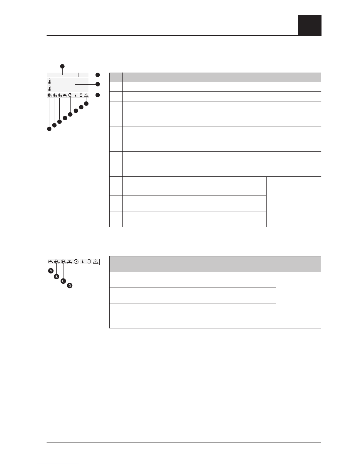
3.1.3 Graphic display
Item Description
1 Shows operating status or menu name
2 Shows the current time
3 Displays the main values in the basic display (adjustable),
menu contents, parameters and info texts
4 Status toolbar
5 Displayed when there is a fault.
Press the info key to display texts describing the fault and the solution.
6 Shows the storage tank loading status (storage tank is optional)
7 Indicates that an info text is displayed. Info texts are also identified by a frame
8 Shows which function is active
⇨ See "Function keys" [page 24]
9 Shows that the DHW tank loading pump is active. Only shown in the
basic display!
10 Shows that the storage tank loading pump is active.
11 Shows that the heating circuit pump of the 2nd heating circuit is
active
12 Shows that the heating circuit pump of the 1st heating circuit is
active.
In the service technician user level, the function of the relevant components is also
shown in the individual status menus by the corresponding status display:
Ite
m
Description
A Shows whether the storage tank (or oil boiler) is hot enough for hot
water preparation
Only for service
technicians in the
status menus
B Shown when the DHW tank or return temperature control pump is
active.
C Shown when the heating circuit or storage tank loading pump is ac‐
tive.
D Shows the status of the heating circuit mixer.
Heating
08:05
Boiler 75°C
Fluegas 150°C
1
2
3
4
5
6
7
8
9
10
11
12
Overview of the basic functions
3
Control keys and display
Operating Instructions Lambdatronic S 3200 | B0361214_en 23
Page 24
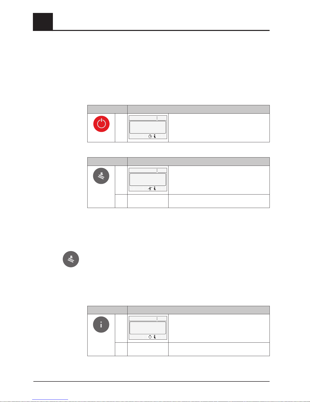
3.2 Function keys
The function keys of the Lambdatronic S 3200 have dual functions. Different functions
can be performed with long or short keystrokes, using the following definitions of key‐
stroke duration:
Short keystroke …….. < 1 second
Long keystroke …….. > 4 seconds
3.2.1 Standby key
Keystroke Function
Heating
08:02
BOILERON
Automaticmodestarted
Heating circuits and domestic hot water are control‐
led according to the programs and times set.
Function remains active until another function key
is pressed.
3.2.2 Service program key
Keystroke Function
Shor
t
Heating
08:02
BOILERON
Chim.sweepmodestarted
The system is operated at nominal load for a period
of 45 minutes.
⇨ See "Chimney sweeper function" [page
24]
Lon
g
Function not used
Chimney sweeper function
The chimney sweep function is used for measuring boiler emissions using the chim‐
ney sweeper. For further information and the procedure for measuring emissions, see
the operating instructions of the boiler and/or the “Instructions for the procedure for
measuring emissions for the firewood boiler”.
Press the service program key
❒
The boiler runs for 45 minutes at nominal load
➥ The boiler temperature setpoint is set to 85 °C
➥ The heating pumps switch on and the mixer valves regulate to the maximum
flow temperature setpoint
➥ DHW tank and storage tank loading pump are controlled as normal
3.2.3 Info key
Keystroke Function
Shor
t
Heating
08:02
===BASICDISPLA
Y ===
Menukeys>>>>2
>>>>Functionkeys3
BasicDisplay9
Shows plain text information about the menu items
or fault messages.
Lon
g
Choose language: Deutsch, Polski, Cesky, Sloven‐
ski, Italiano, Francais, English
3
Overview of the basic functions
Function keys
24 Froling GesmbH | A-4710 Grieskirchen, Industriestraße 12 | www.froeling.com
Page 25
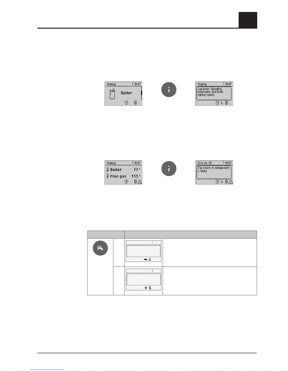
The info key can be pressed at any time and always shows information about the cur‐
rent menu item or the current fault message, with fault messages occupying the high‐
est priority.
Info key in normal mode:
In normal operation (without pending
fault messages) the info key can be
pressed to display information or an
explanation for every menu item or pa‐
rameter.
The info text is also identified by the
frame and the info symbol on the sta‐
tus line.
Info key when there is a pending fault:
If a fault has been acknowledged after
arising, but not resolved, this is shown
by a warning symbol at the bottom right
on the status line.
Pressing the info key calls up the infor‐
mation on the currently pending fault
message again.
Procedure for troubleshooting:
⇨ See "Troubleshooting" [page
83]
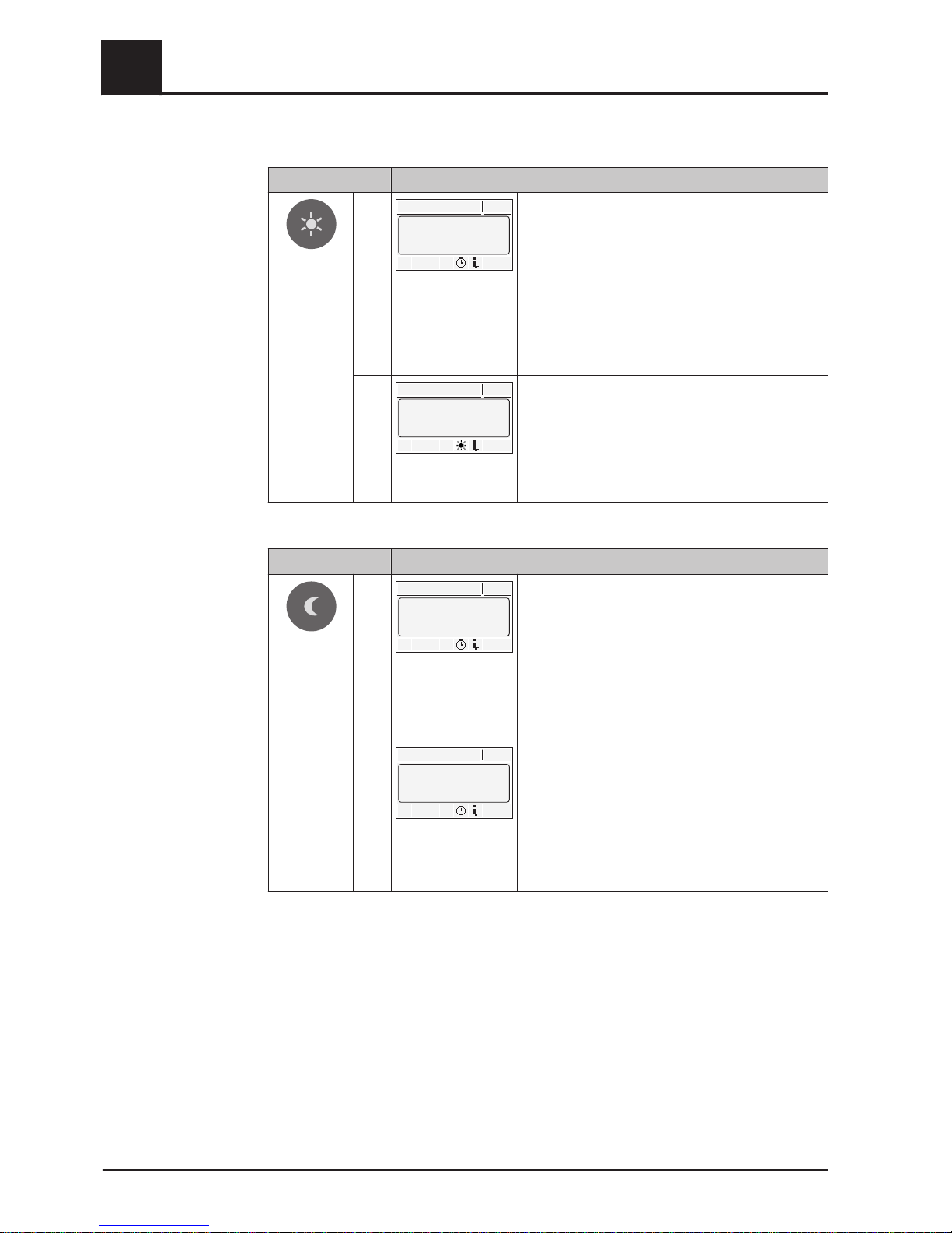
3.2.4 DHW tank program key
Keystroke Function
Shor
t
Heating
08:02
BOILERON
ExtraDHWloadingstarted
Single manual loading of domestic hot water.
The function is indicated during DHW tank loading
by the tap symbol on the status line. After loading,
the mode that was previously set becomes active
again.
Lon
g
Heating
08:02
BOILERON
Summermodestarted
To change to summer mode.
The mode is indicated by the tap symbol on the sta‐
tus line. Domestic hot water loading is controlled
according to the program that is set, the heating cir‐
cuit controller is deactivated.
Overview of the basic functions
3
Function keys
Operating Instructions Lambdatronic S 3200 | B0361214_en 25
Page 26
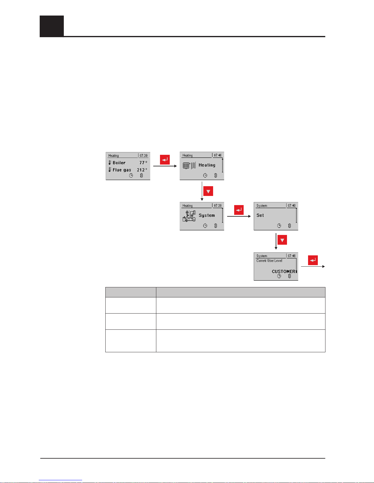
3.2.5 Party program key
Keystroke Function
Shor
t
Heating
08:02
P
ARTY MODEisnot
possibleinboilerdisplay!
To activate party mode on the room console.
Caution: Function only possible on the room con‐
sole!
After an optional change to the room temperature
setpoint, the heating circuit controller remains in
heating mode until the end of the next heating peri‐
od or another mode is activated. This function is not
possible in summer mode!
Observe the additional information in the operating
instructions of the room console.
Lon
g
Heating
08:02
BOILERON
Extraheatingstarted
During extra heating, heating and domestic hot wa‐
ter are heated for 6 hours. The mode setting is ig‐
nored. The function is indicated by the sun symbol
in the status line.
Caution: The external temperature heating limit set
in the "Heating" menu is active and can prevent re‐
lease of the heating circuits.
3.2.6 Setback program key
Keystroke Function
Shor
t
Heating
08:02
SetbackMODEisnot
possibleinboilerdisplay!
To activate setback mode on the room console.
Caution: Function only possible on the room con‐
sole!
After an optional change to the setback tempera‐
ture the heating circuit controller remains in setback
mode until the start of the next heating time or until
activation of another mode.
Observe the additional information in the operating
instructions of the room console.
Lon
g
Heating
08:02
CONTINUOUSsetback
MODEisnotpossiblein
boilerdisplay!
To activate continuous setback mode on the room
console.
Caution: Function only possible on the room con‐
sole!
The room temperature is reduced to the preset set‐
back temperature until automatic mode is activated.
Observe the additional information in the operating
instructions of the room console.
3
Overview of the basic functions
Function keys
26 Froling GesmbH | A-4710 Grieskirchen, Industriestraße 12 | www.froeling.com
Page 27

4 Operation
❒ Before the initial startup check the wiring of the pumps and mixers is correct.
⇨ See "Before switching on for the first time" [page 27]
❒
Check that the connected components have maximum connected load.
Core module or
⇨ See "expansion modules" [page 12]
4.1 Before switching on for the first time
NOTICE
You should have the initial startup carried out by the authorised heating engineer
from Froling customer services.
4.1.1 Controller check
❒ Check boards for foreign bodies (pieces of wire, washers, screws ...)
❒
Carry out a wiring check:
Check for loose, uninsulated wires, which could cause a short-circuit
❒ Check plug configuration of pumps, mixing valves and other units, which have
NOT been prepared by Froling
❒ Check the connection of the BUS cable for short-circuits
❒ Check the specified addresses and terminal jumpers on the individual modules
(heating circuit modules, hydraulic modules, displays etc.)
⇨ See "Setting the module address" [page 20] and
⇨ See "Setting end jumpers" [page 19]
4.1.2 Check on the connected units
❒ Check that all units that are used are connected correctly
❒
Carry out a wiring check:
Check for loose or uninsulated wires in the terminal boxes of the pumps,
mixer and switch valve, which could cause a short-circuit
4.1.3 System Check
❒ Check that the main fuse for the boiler has a sufficient rated amperage (16A )
➥ If a safety overload switch is used, it should be a type with
16A.
Operation
4
Before switching on for the first time
Operating Instructions Lambdatronic S 3200 | B0361214_en 27
Page 28
4.2 Initial startup
After power up and when the main switch has been switched on, the start logo is dis‐
played and the controller carries out a system check.
After the system check the basic display is shown. The basic display is shown as
standard, giving information about the two most important parameters, and the display
can be adjusted individually.
⇨ See "Basic display parameters" [page
79]
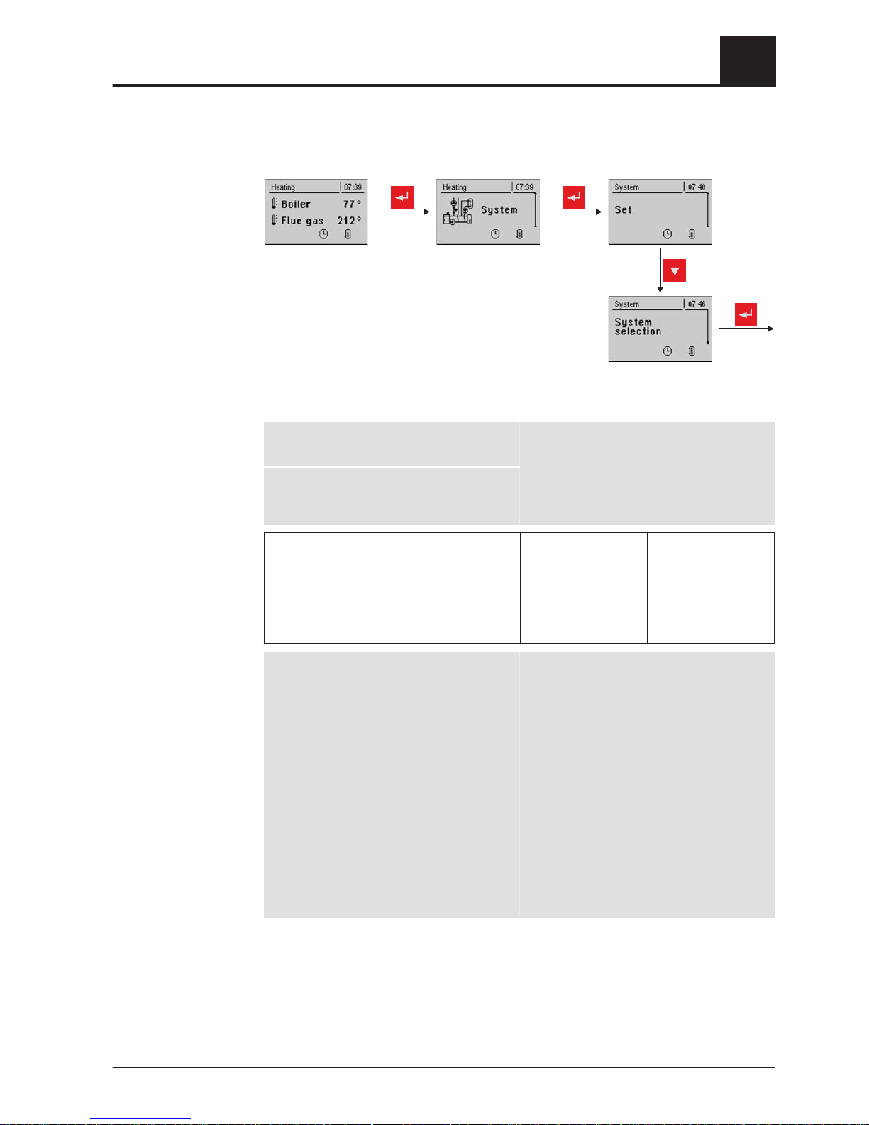
4.2.1 Changing the operating level
For safety reasons individual parameters are only visible at specific operating levels.
To change to another level it is necessary to enter the relevant user code:
repeatedly
repeatedly
Operating level Description
Child lock
(Code 0)
At "Child lock" level, only the basic display is shown.
It is not possible to change parameters at this level.
Customer
(Code 1)
Standard level for normal operation of the controller. All customer-spe‐
cific parameters are displayed and can be changed.
Installer / Service Releases parameters to adjust the controller to the system components
(if configured). All the parameters shown in these operating instructions
are available.
4
Operation
Initial startup
28 Froling GesmbH | A-4710 Grieskirchen, Industriestraße 12 | www.froeling.com
Page 29
4.2.2 Setting the system type
NOTICE! Only for trained personnel – installer code must be entered.
repeatedly
Boiler type
Warning! Incorrect settings can lead to faults.
Continue with the DOWN arrow key
DO NOT SELECT!
S1 Turbo
S3 Turbo / ECO
S4 Turbo ➔ S4 boiler types: S4 Turbo 15
S4 Turbo 22
S4 Turbo 28
S4 Turbo 32/34
S4 Turbo 40
S4 Turbo 50
S4 Turbo 60
SP Dual
FHG Turbo 3000 20
:
FHG Turbo 3000 70
P1 Pellet 7 - 20
Pellet boiler P2 – 10
:
Pellet boiler P2 – 25
P4 Pellet 8 – 25
P4 Pellet 32 - 105
Turbomatic 25 – 55
Turbomatic 70 – 100
T4 24 – 75
T4 90 – 150
TX 150
TX 200 – 250
Wood boiler F2 22/30
DO NOT SELECT!
Operation
4
Initial startup
Operating Instructions Lambdatronic S 3200 | B0361214_en 29
Page 30
Boiler type parameters
Lambda probe installed YES
Actuators installed YES
Ignition available YES
Bypass pump installed NO
Return mixer using HC1 NO
Return mixer using external mixer module NO
NOTE: Once all the relevant parameters have been set, the boiler standard values
need to be entered in the “Boiler” menu under “General settings”.
Parameter Description
Very dry material NO If this parameter is set to "YES" and the boiler standard
values are adopted, the parameters are automatically
adjusted for very dry firewood.
Adopt boiler standard val‐
ues
NO If this parameter is set to "YES", the current parameters
for the selected boiler are set. After the values have
been adopted the parameter jumps to "NO"
System selection
Hydraulic system 0
Hydraulic system 1
Hydraulic system 2
Hydraulic system 3
Hydraulic system 4
SELECT
For description see “ Lambdatronic S 3200
Energy Systems” brochure
Hydraulic system for S3 boiler DO NOT SELECT
Hydraulic system 12
Hydraulic system 13
SELECT
For description see “ Lambdatronic S 3200
Energy Systems” brochure
Variant 1
Variants 2 and 5
Variant 3
Variant 4
Multiple house diagrams
Slave boiler for boiler sequence control Only for systems in the cascade!
repeatedly
4
Operation
Initial startup
30 Froling GesmbH | A-4710 Grieskirchen, Industriestraße 12 | www.froeling.com
Page 31
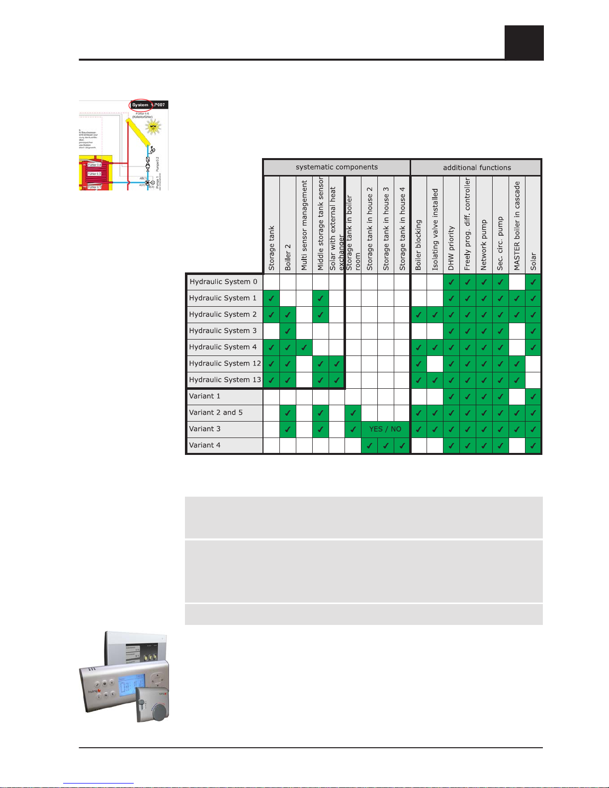
If the system has a Non-binding Planning Suggestion, the hydraulic system setting
can be found at the top right-hand corner of the planning suggestion.
Otherwise, the selection table below shows the hydraulic system to be set for the spe‐
cific system:
Hydraulic System
DHW tank system DHW tank 01 installed
:
DHW tank 08 installed
YES / NO
:
YES / NO
Heating system Heating circuit 01 installed
Remote control 01 installed
:
Heating circuit 18 installed
Remote control 18 installed
YES / NO
YES / NO
:
YES / NO
YES / NO
Solar system Solar collector 01 installed YES / NO
❒ The “remote control XX installed” parameter should be set to “YES” if
any of the three remote controls shown is used for the respective heating circuit.
Operation
4
Initial startup
Operating Instructions Lambdatronic S 3200 | B0361214_en 31
Page 32

Boiler remote control
Remote control of the boiler can be activated NO
❒ This menu item or parameter is only relevant for systems equipped with touch
control and also use the internet portal
froeling-connect.com!
4.2.3 Before heating up for the first time
❒ Check the system pressure of the heating system
❒
Check that the heating system is fully ventilated
❒ Check that the safety devices are present and working correctly
❒ Check that there is sufficient ventilation in the boiler room
❒ Check the seal of the boiler
➥ All doors and inspection openings must be tightly sealed!
❒ Broadband probe calibration
⇨ See "Starting calibration" [page 74]
❒ Door switch is working correctly
⇨ See "Digital inputs" [page 68]
Drives
❒ Check that drives and actuators are working and turning in the right direction
⇨ See "Analogue outputs" [page 67] and
⇨ See "Digital outputs" [page 67]
4.3 Heating up the boiler
When starting up for the first time ensure that the combustion chamber heats up slow‐
ly. Information on safety and implementation in the operating instructions of the boiler
must be observed.
NOTICE! See chapter on Initial Startup in the assembly instructions of the boiler
4
Operation
Initial startup
32 Froling GesmbH | A-4710 Grieskirchen, Industriestraße 12 | www.froeling.com
Page 33
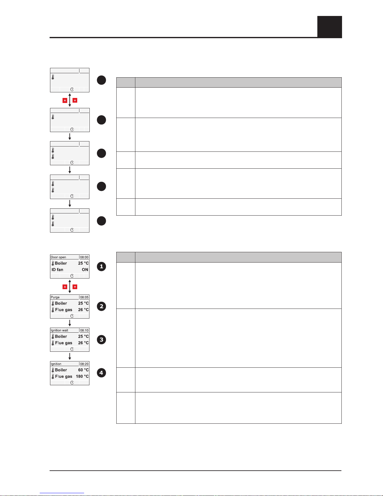
4.3.1 Heating up
Item Description
1 When the insulated door is opened the status, "Door open", is shown on the display
and the basic display is replaced by the flue gas temperature and the parameter "ID
fan". The parameter is automatically set to "ON" and the ID fan is activated at maxi‐
mum speed.
2 The ID fan can be switched on and off with the arrow keys.
NOTICE! When igniting the paper, it is advisable to turn off the induced draught fan
and to turn it on again afterwards.
▪
Fill the boiler with fuel and ignite it following the boiler operating instructions
3 After closing the insulated door the boiler switches automatically to "Heating up"
status. The Lambdatronic S 3200 activates the induced draught at 100%.
4 When a specific minimum flue gas temperature is reached or when the specified maxi‐
mum heating up time has elapsed, the boiler changes to "Heating" status. The
Lambdatronic S 3200
controls the combustion according to the boiler setpoints that
have been set.
5 If the criteria for "Heating" status are not reached within a specified time, the boiler
switches to "Off" status.
4.3.2 Heating up with automatic ignition
Item Description
1 When the insulated door is opened the status "Door open" is shown on the display
and the basic display is replaced by the flue gas temperature and the parameter "ID
fan". The parameter is automatically set to "ON" and the ID fan is activated at maxi‐
mum speed.
❒
Fill the boiler with fuel
NOTICE! See operating instructions for the S4 Turbo firewood boiler
2 The ID fan can be switched on and off with the arrow keys.
After closing the insulated door the boiler automatically switches to "Preventilation"
status.
To guarantee a safe boiler operating status and to rule out possible ignition by residu‐
al embers due to incomplete cleaning of the combustion chamber, the boiler attempts
to reach "Heating" status within a specified safety time without activating the ignition.
Within this time period, heating up can be carried out manually, to bypass the auto‐
matic ignition.
3 Once this safety time has passed, the boiler remains in “Ignition wait” status until the
time for automatic ignition set in the Ignition menu is reached.
⇨ See "Menu - Ignition" [page 59]
4 The fuel is ignited with the fan-assisted ignition. The boiler must reach the criteria for
“heating” status within a specified time. If the ignition attempt fails, an error is shown
on the display.
⇨ See "Troubleshooting" [page
83]
Dooropen
08:00
Boiler 25°C
IDFan ON
Dooropen
08:00
Boiler
25°C
IDFan OFF
Heatingup
08:01
Boiler
25°C
Fluegas 26°C
Heating
08:15
Boiler 60°C
Fluegas
180°C
1
2
3
4
Off
09:35
Boiler 30°C
Fluegas
38°C
5
Operation
4
Heating up the boiler
Operating Instructions Lambdatronic S 3200 | B0361214_en 33
Page 34
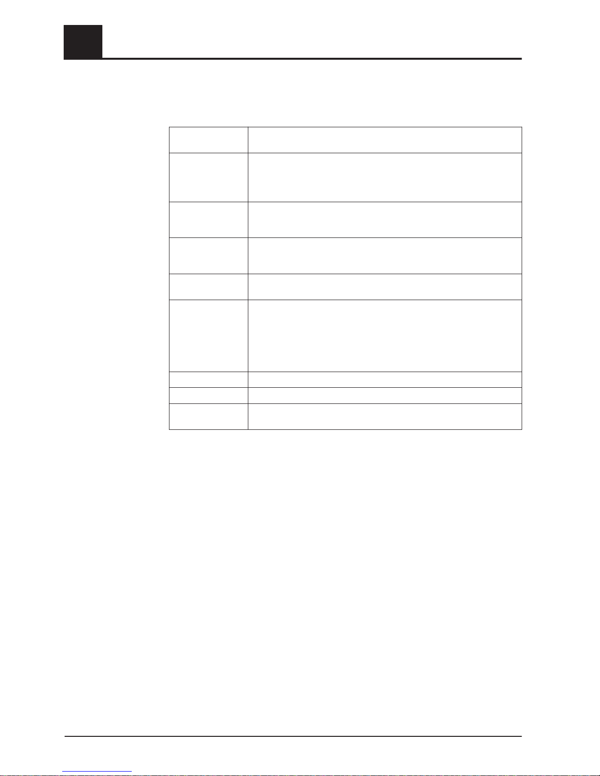
4.4 Operating statuses
The different operating statuses are displayed at the top left of the visual display:
Heating up Boiler status during the heating up process up to a certain minimum flue
gas temperature. Fan and primary air at 100%
Preventilation
(with autom. igni‐
tion)
Safety function with operation with automatic ignition.
Within a specified time the boiler attempts to reach the status Heating
without activating the ignition. Within this time period, heating up can be
carried out manually, to bypass the automatic ignition.
Ignition wait
(with autom. igni‐
tion)
When the safety time has elapsed (operating status preventilation) the
boiler remains in the status "ignition wait" until the time specified in the
ignition menu for the automatic ignition has been reached.
Ignition
(with autom. igni‐
tion)
The fuel is ignited with fan assistance. The boiler attempts to reach the
criteria for heating status within a specified time.
Heating The Lambdatronic S 3200 controls combustion according to the boiler
setpoints.
Slumber Very low power consumption.
When the boiler temperature setpoint is exceeded by a specified value,
the boiler goes to "Slumber" status. The fan stops and the air flaps are
closed to the minimum opening.
If the temperature falls below the boiler temperature setpoint the boiler
goes back to “heating" status.
Door open The insulating door is open and the fan runs at maximum speed.
Off The boiler burns down to residual embers.
Fault WARNING - There is a fault!
Troubleshooting
4
Operation
Operating statuses
34 Froling GesmbH | A-4710 Grieskirchen, Industriestraße 12 | www.froeling.com
Page 35
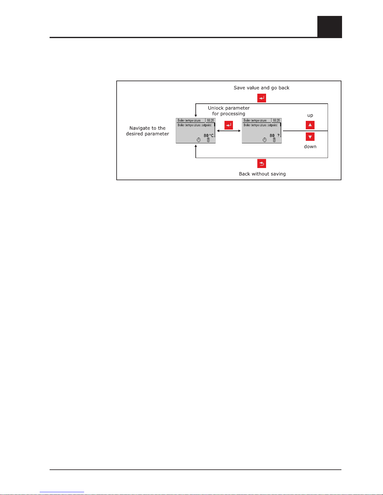
4.5 Setting parameters
Values for all parameters are changed in the following way:
For initial startup the following parameters should be checked and adjusted if required:
▪ Heating curve: Radiator or underfloor heating
⇨ See "Temperature settings for the heating circuit" [page
39]
The other parameters are factory set in such a way that in most cases optimal opera‐
tion is possible without making further changes to the parameters.
The following parameters, however, can/should be set as desired by the customer:
▪ Desired boiler setpoint
⇨ See "Setting parameters – Boiler temperature" [page 69]
▪ DHW tank loading times
⇨ See "Heating times of the DHW tank" [page 45]
▪ Solar controller
⇨ See "Menu - Solar" [page 46]
▪ Heating and setback times of the individual heating circuits
⇨ See "Heating times of the heating circuits" [page 40]
4.6 Setting times
The desired time window for the components can be set in the "Times" submenu in
the individual menus of the heating components (heating circuits, DHW tanks ...). The
structure of the time menu and the procedure for changing the times are always the
same.
Example - Setting times for heating circuit 01:
In the "Heating" menu -> "Times":
Operation
4
Setting parameters
Operating Instructions Lambdatronic S 3200 | B0361214_en 35
Page 36
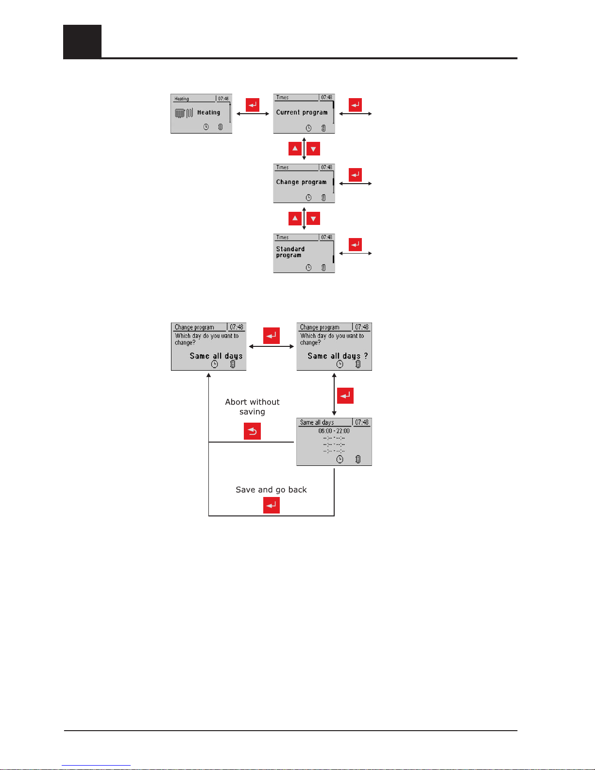
Current settings for the individual
weekdays are displayed. Press‐
ing the arrow keys changes to the
next/previous weekday
See example below…
The factory set times are loaded
by confirming again. (06:00 –
22:00)
Caution - the customer specific
time settings are lost in the proc‐
ess!
… In the "Change program" menu:
After pressing the enter key you
can select the day or the time pe‐
riod, for which the heating times
are to be set:
- MO, TU, .., SU
- MO - FR
- SA - SU
- SAME ALL DAYS
After pressing the enter key again
the time window for the desired
day/time period is displayed.
Up to 4 different heating times
can be entered consecutively
here.
When the enter key is pressed,
the cursor jumps to the next posi‐
tion, even if no time has been en‐
tered. If the cursor is in the last
position, pressing the enter key
saves the time window and
switches to the previous menu
4.6.1 Deleting a time window
To delete a time window, the end time of the desired time window must be set to
24:00. If you press the up arrow key repeatedly the time disappears and is replaced by
dashes. Then carry out the same process with the start time. After the enter key has
been pressed repeatedly, the changes are adopted and the display returns to the pre‐
vious menu.
4
Operation
Setting times
36 Froling GesmbH | A-4710 Grieskirchen, Industriestraße 12 | www.froeling.com
Page 37
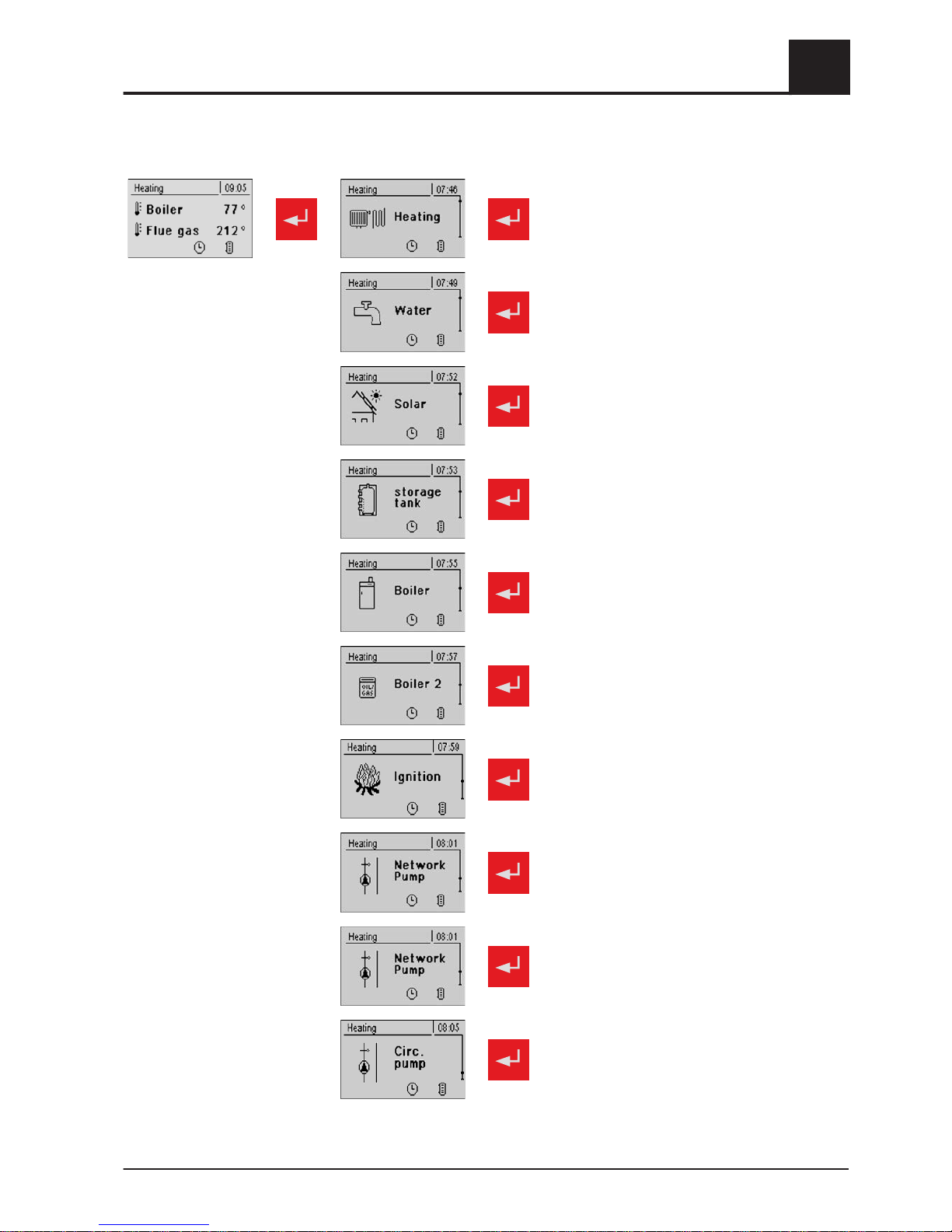
5 Menu overview and parameters
⇨ See "Menu - Heating" [page 38]
⇨ See "Menu - Water" [page 43]
⇨ See "Menu - Solar" [page 46]
⇨ See "Menu - Storage tank" [page 51]
⇨ See "Menu - Boiler" [page 55]
⇨ See "Menu - Boiler 2" [page 57]
⇨ See "Menu – Ignition S4" [page 59]
⇨ See "Menu - Network pump" [page 60]
⇨ See "Menu – Diff. control" [page 62]
⇨ See "Menu - Circulation pump" [page 64]
Menu overview and parameters
5
Operating Instructions Lambdatronic S 3200 | B0361214_en 37
Page 38
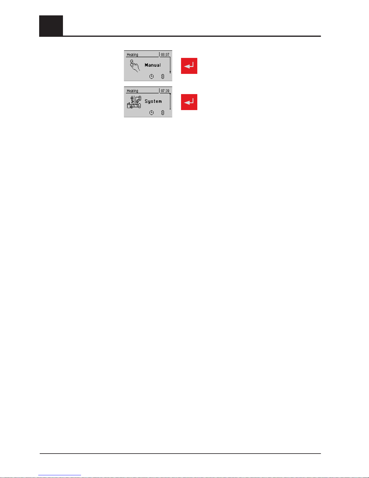
⇨ See "Menu - Manual" [page 66]
⇨ See "Menu - System" [page 68]
5
Menu overview and parameters
Menu - Heating
38 Froling GesmbH | A-4710 Grieskirchen, Industriestraße 12 | www.froeling.com
Page 39
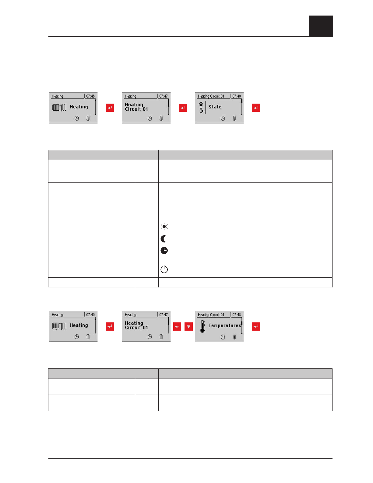
5.1 Menu - Heating
5.1.1 Status displays for the heating circuits
Heatingcircuit
01...18
Parameter Description
Control heating circuit according to
program (NO -> heating circuit is
switched off)
YES NO -> Heating circuit is completely switched off. No frost protection!
Actual flow temperature 46°C Shows the current flow temperature
Flow temperature setpoint 52°C The calculated flow temperature setpoint
Room temperature 21°C Temperature on remote control of the current heating circuit (optional)
Override switch Auto Shows the current switch setting on the remote control (optional)
(Party) = party mode; the setback program is ignored
(Setback) = setback mode; the heating phases are ignored
(Auto) = automatic mode; heating phases according to setback
program
(Off) = switched off; heating circuit deactivated, only frost protection!
External temperature 2°C Shows the current external temperature
5.1.2 Temperature settings for the heating circuit
Heatingcircuit
01...18
Parameter Description
Desired room temperature during
heating mode
20°C Room temperature during heating mode (only with remote control)
Desired room temperature during
setback mode
16°C Room temperature during setback mode (only with remote control)
Menu overview and parameters
5
Menu - Heating
Operating Instructions Lambdatronic S 3200 | B0361214_en 39
Page 40
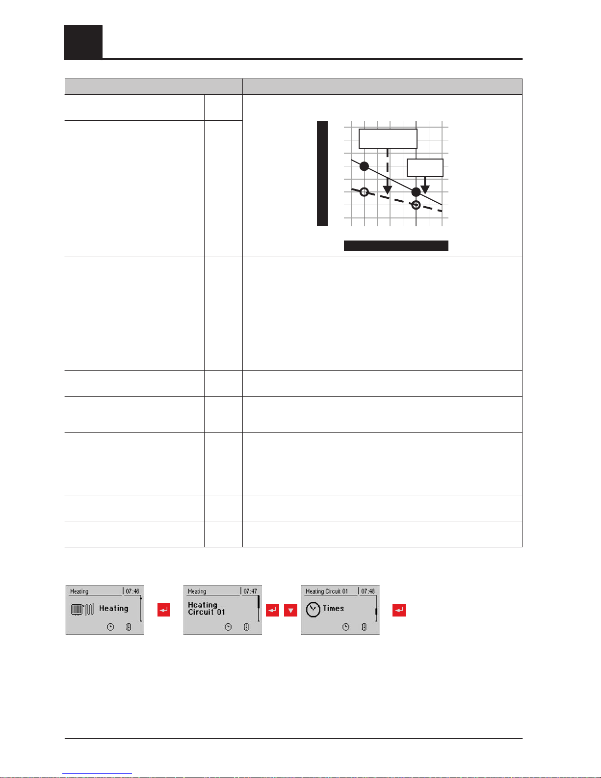
Parameter Description
Flow temperature SP at external
temperature of +10°C
40°C The heating curve can be adjusted to the relevant system with these two
work points.
90
80
70
60
50
40
30
20
Flowtemperature
-10
External temperature
-15 -5 0 5 10 15
20
Exampleof
floorheating
Exampleof
radiators
Flow temperature SP at external
temperature of -10°C
60°C
Controller gain room temperature
Kp-Rm
6.0 Influencing factor of room temperature on the flow temperature of the
heating circuit. If there is a deviation in the room temperature of +/- 1°C
the set value of the flow temperature is corrected by this value.
(Parameter only with optional remote control!)
Recommended values for:
- Floor heating 2 - 3
- Radiators (new build): 4 – 5
- Radiators (old build): 6 – 7
Note:Observe external influences on the room sensors!
Reduction of flow temperature in
setback mode
15°C The flow temperature is reduced by this value during setback mode.
External temperature below which
the heating circuit pump switches on
in heating mode
18°C If the external temperature exceeds this value during heating, the heating
circuit pumps and mixing valve are deactivated.
External temperature below which
the heating circuit pump switches on
in setback mode
7°C If the external temperature falls below this value in setback mode, the
heating circuit pumps and mixing valve are activated.
Maximum heating circuit flow temp. 75°C Maximum temperature for limiting outfeed temperature at which the heat‐
ing circuit is supplied.
Maximum DHW tank flow temp. 75°C If DHW tank 1 is supplied directly from heating circuit 1, you can set anoth‐
er maximum flow temperature for the time of DHW tank loading.
Frost protection temperature 10°C If the room temperature or the flow temperature is lower than the set val‐
ue, the heating circuit pump will be switched on.
5.1.3 Heating times of the heating circuits
repeatedly
Heatingcircuit
01...18
⇨ See "Setting times" [page 35]
5
Menu overview and parameters
Menu - Heating
40 Froling GesmbH | A-4710 Grieskirchen, Industriestraße 12 | www.froeling.com
Page 41
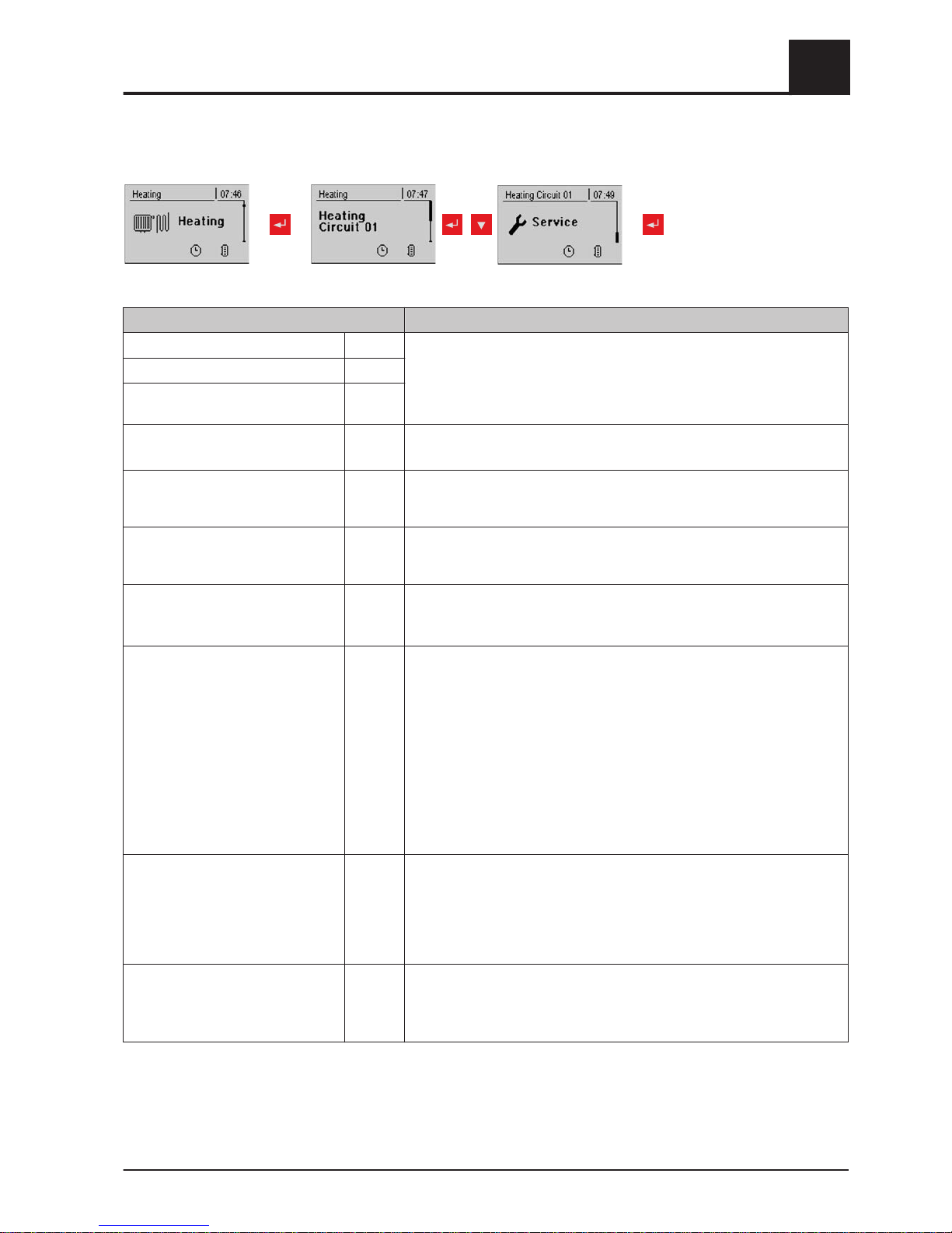
5.1.4 Service parameters of the heating circuits
repeatedly
Heatingcircuit
01...18
Parameter Description
Heating circuit pump A 0 Used for testing the individual outputs.
Heating circuit mixing valve OPEN A 0
Heating circuit mixing valve
CLOSED
A 0
Mixer runtime 240s Set mixer runtime of heating circuit mixer in use.
Recommendation to reduce mixer vibration: do not set to < 150 s
Switch off heating circuit pump
when flow setpoint is lower than
20°C If a flow temperature setpoint is calculated below the value set here, the
heating circuit pump switches off and the mixing valve closes (just without
remote control).
Should this heating circuit heat
when there is DHW tank priority?
NO Generally the heating circuits are released with active DHW tank priority
only when the DHW tank is fully charged. If this parameter is set to "YES",
the DHW tank priority for this heating circuit is deactivated.
From which storage tank or distribu‐
tor is the heating circuit supplied (0
= boiler)
1 NOTE: Only valid for multiple house systems (variants).
Allocation of the heating source for this heating circuit:
0 = Boiler, 1 = Storage tank 01, ...
High temperature requirement be‐
cause of DHW tank 1 loading
NO If DHW tank 1 is supplied directly from the heating circuit as well as the
isolating valve, this parameter must be set to “YES”. If there is a require‐
ment from the DHW tank and the criteria for DHW tank loading have been
met, the isolating valve immediately clears the way for boiler loading. The
heating circuit pump starts running as soon as the “Load if tempera-
ture difference between boiler and DHW tank is” criterion
is reached. Once DHW tank loading is complete, the heating circuit pump
will stop, the isolating valve will remain active for a specified period of time
and the heating circuit mixer will close. If time has run out, the heating cir‐
cuit will go back to being supplied on a weather-compensated basis.
NOTE: Parameter only available with heating circuit 1 and generally only
used in conjunction with the unit model of the P1 Pellet pellet boiler!
High temperature requirement be‐
cause of DHW tank loading
NO If this parameter is set to YES, the remote line is operated according to
the set heating curve + overcharge. Whilst the DHW tank is loading, the
remote line is supplied for a short time at a higher temperature, but once
the DHW tank is loaded, it is supplied again according to the heating
curve.
NOTE: Parameters for heating circuit 2 only!
For high temperature requirement
don't look at DHW tank 01
NO If DHW tank 1 is positioned in front of the network mixer, it should not af‐
fect the temperature control of the remote line, therefore this parameter
should be set to YES.
NOTE: Parameters for heating circuit 2 only!
Menu overview and parameters
5
Menu - Heating
Operating Instructions Lambdatronic S 3200 | B0361214_en 41
Page 42
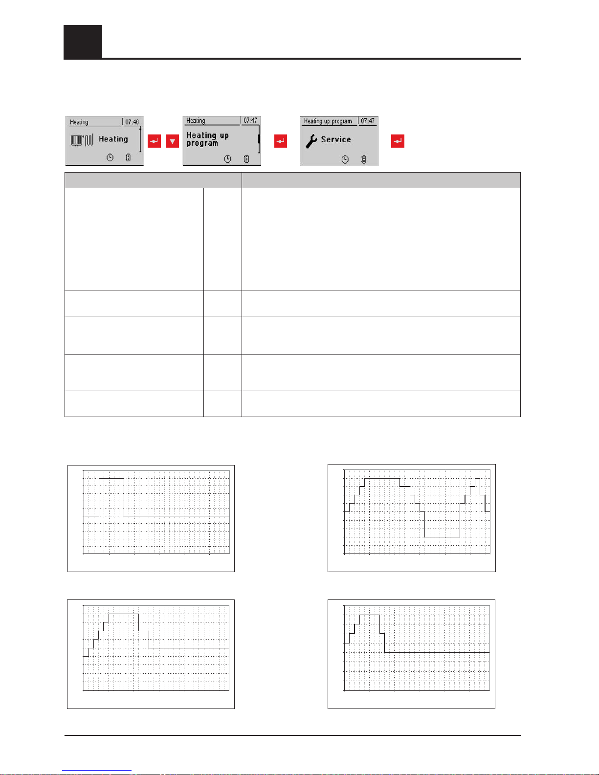
5.1.5 Service parameters for heating up program
Parameter Description
Heating up program active NO If this parameter is activated, the 30-day program that has been set starts.
After the 30 days, the heating circuit that has been set operates based on
the set heating times again.
❒
The heating times of the selected heating circuit are automatically set
to 0:00-24:00 and the external temperature heating limit is ignored.
❒ In order that enough heat is always available to the heating circuit, the
boiler and/or storage tank loading times must be set to 0:00-24:00.
When using a firewood boiler, a corresponding heat supply must be
ensured.
Current day of the heating up pro‐
gram
1 Shows the current day of the heating program that is running
For which heating circuit should the
program apply
1 This parameter determines which heating circuit is supplied by the heating
up program. Heating circuit 1 ... 18
❒
Only one heating circuit can be selected.
Which heating up program is used 1 There are set options for the progression of the flow temperature in heat‐
ing up programs 1 – 6. With heating up program 7 the flow temperature
can be selected freely.
Outfeed setpoint for all days in pro‐
gram 7
35°C If heating up program 7 is active, the selected heating circuit is adjusted to
the specified flow temperature.
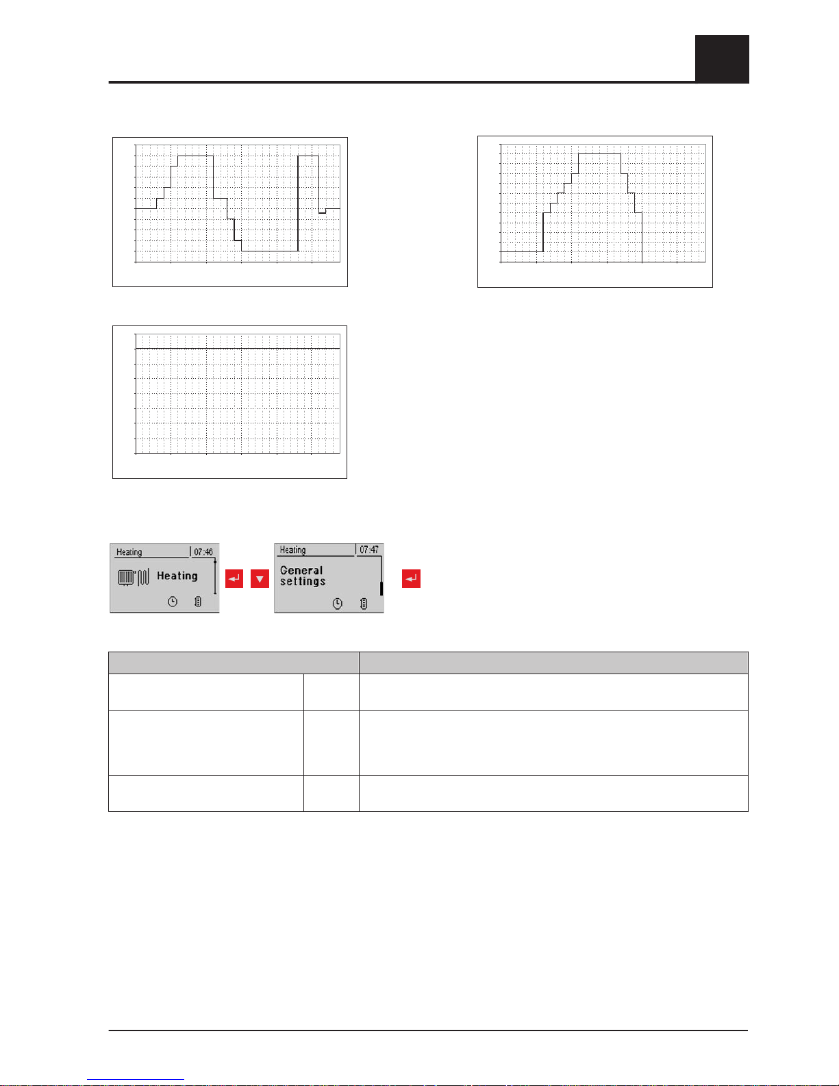
Heating up programs
Heating up program 1:
0
5
1
0
15
20
25
30
35
40
45
50
55
1 6 11 16 21 26
Day
Flow temp. setpoint [°C]
30
Heating up program 2:
0
5
10
15
20
25
30
35
40
45
50
1 6 11 16 21 26
Day
Flow temp. setpoint [°C]
30
Heating up program 3:
0
5
1
0
15
20
25
30
35
40
45
50
1 6 11 16 21 26
Day
Flow temp. setpoint [°C]
30
Heating up program 4:
0
5
1
0
15
20
25
30
35
40
45
1 6 11 16 21 26
Day
Flow temp. setpoint [°C]
30
5
Menu overview and parameters
Menu - Heating
42 Froling GesmbH | A-4710 Grieskirchen, Industriestraße 12 | www.froeling.com
Page 43
Heating up program 5:
0
5
1
0
15
20
25
30
35
40
45
50
55
1 6 11 16 21 26
Day
Flow temp. setpoint [°C]
30
Heating up program 6:
0
5
1
0
15
20
25
30
35
40
45
50
55
60
1 6 11 16 21 26
Day
Flow temp. setpoint [°C]
30
Heating up program 7:
0
5
1
0
15
20
25
30
35
40
1 6 11 16 21 26
Day
Flow temp. setpoint [°C]
30
The heating up programs listed are non-binding rec‐
ommendations. If the heating up program is to be
used for floor screed drying, you must consult the
manufacturer of the floor finish and/or the installer
5.1.6 General settings
repeatedly
Parameter Description
Correction value
for external sensor
0°C If the outside temperature sensor shows an incorrect value, the value can
be adjusted using this parameter.
Heating circuit module to
which the external sensor is con‐
nected
(0 = core module)
0 If the outside temperature sensor is not connected to the core module, the
address of the relevant heating circuit module +1 must be set here. (Sen‐
sor 1 on relevant module)
Use room temperature sensor input
for room thermostat
NO If room thermostats are used instead of room temperature sensors, this
parameter must be set to YES.
Menu overview and parameters
5
Menu - Heating
Operating Instructions Lambdatronic S 3200 | B0361214_en 43
Page 44
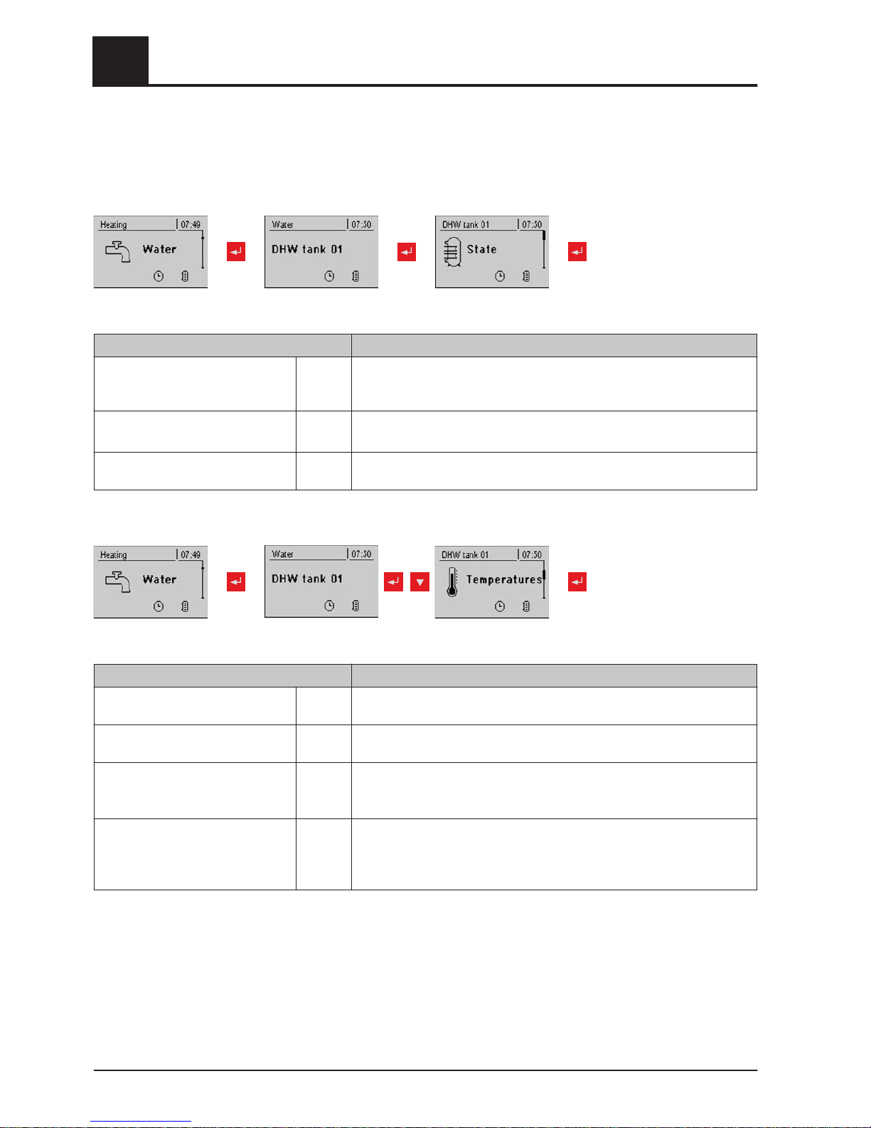
5.2 Menu - Water
5.2.1 Status displays for the DHW tank
DHWtank01...08
Parameter Description
DHW tank top temperature 60°C Current temperature in the top part of the DHW tank. The DHW tank is
heated during the loading times until the specified parameter, "Set DHW
temperature", is reached.
DHW tank bottom temperature 55°C Current temperature in the lower part of the DHW tank.
(Parameter only available with solar element)
DHW tank pump control 0% Specifies the speed of the DHW tank pump as a percentage of the maxi‐
mum speed
5.2.2 Temperature settings of the DHW tank
DHWtank01...08
Parameter Description
DHW setpoint 55°C When this DHW tank temperature is reached the DHW tank loading pump
switches off.
Reload if DHW tank temperature is
below
45°C Reloading of the DHW tank is authorised when the DHW tank temperature
is below this level.
Load if temperature difference be‐
tween storage tank and DHW tank
is
6°C When the storage tank top temperature is above the DHW tank tempera‐
ture by this value, the DHW tank loading pump is released.
(Only for systems with storage tanks)
Load if temperature difference be‐
tween boiler and DHW tank is
6°C Initial value of DHW tank loading. The boiler temperature must be higher
than the DHW tank temperature by this value so that the DHW tank load‐
ing process begins.
(Only for systems without storage tanks)
5
Menu overview and parameters
Menu - Water
44 Froling GesmbH | A-4710 Grieskirchen, Industriestraße 12 | www.froeling.com
Page 45
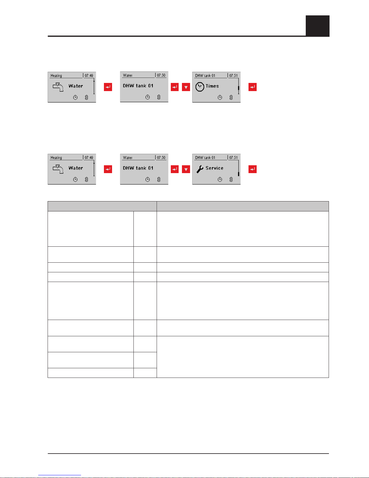
5.2.3 Heating times of the DHW tank
repeatedly
DHWtank01...08
⇨ See "Setting times" [page 35]
5.2.4 Service parameters of the DHW tank
repeatedly
DHWtank01...08
Parameter Description
Residual heat use NO Function can only be used with systems with return mixer and no storage
tank. This diverts the residual energy to the DHW tank, the "Above
Boiler temp pumps start” parameter is ignored. The pump is acti‐
vated at minimum speed until the boiler temperature is lower than the
DHW tank temperature + 3°C.
Only load DHW tank once a day NO If this parameter is set to "YES", repeated heating on one day is preven‐
ted.
Legionella heating activated YES The DHW tank is heated to at least 65°C once a week.
Which day for legionella heating MO Day of the week on which the Legionella heating is carried out.
Which storage tank or heat distribu‐
tor supplies the heat to this DHW
tank (0 = boiler)
1 When using several storage tanks or heat distributors, the source of heat
for DHW tank loading is selected here.
If only one storage tank or heat distributor is used, leave the parameter at
the default setting of 1.
NOTE: Only valid for multiple house systems.
DHW tanks run-on (this parameter
applies for all DHW tanks)
0m Run-on time for all DHW tanks
Which sensor is used for top DHW
tank 1
0.3 Bus address of the sensors and pumps used.
⇨ See "Setting the module address" [page
20]
Which sensor is used for solar refer‐
ence DHW tank 1
0.4
Which pump is used for DHW tank 1 0.2
Menu overview and parameters
5
Menu - Water
Operating Instructions Lambdatronic S 3200 | B0361214_en 45
Page 46
Parameter Description
PWM setting for DHW tank pump Normal
pump
▪ Normal pump
▪
PWM / field pump
▪ PWM / solar pump
▪ PWM field pump + valve
▪ 0 – 10V / field pump
▪ 0 – 10V / solar pump
▪ 0 – 10V field pump + valve
Properties of the respective setting:
⇨ See "PWM / 0 - 10V settings" [page 81]
Minimum DHW tank pump speed 45% Adjustment of the minimum speed to the pump type. (Set the pump mode
according to pump manufacturer’s instructions)
Maximum DHW tank pump speed 100% If you need to limit the maximum speed of the DHW tank pump for system‐
ic reasons, you can do so by adjusting this parameter.
5
Menu overview and parameters
Menu - Solar
46 Froling GesmbH | A-4710 Grieskirchen, Industriestraße 12 | www.froeling.com
Page 47
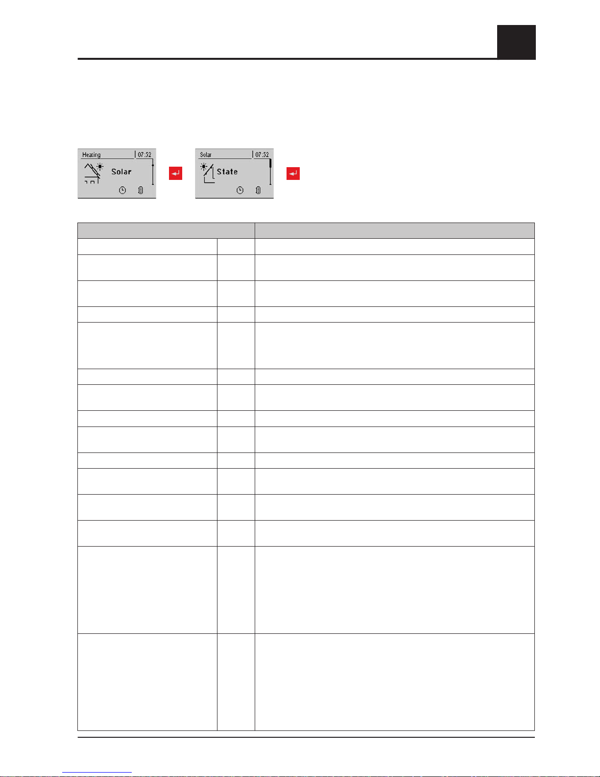
5.3 Menu - Solar
5.3.1 Status displays for the solar system
Parameter Description
Collector Temperature 80°C Current temperature at collector.
Solar temperature bottom storage
tank
43°C Current temperature at solar sensor at bottom of storage tank.
Collector return feed temperature 50°C Current temperature at collector return.
(Only for systems 12, 13)
Current output of Solar WMZ [kW] 0.00 Displays current output of solar collector.
DFL Sensor [l/h] 0 Display of the water quantity currently being pumped through the solar col‐
lector.
NOTE: Display is active only if an external volume flow sensor is used and
it has been activated in the controller.
Todays yield [kWh]] 0 Heat quantity that has been supplied by the solar panel system today
Total yield [kWh] 0 Heat quantity that has been supplied since activation of the solar panel
system
DHW tank bottom temperature 39°C Current temperature at the solar reference sensor in the DHW tank.
Heat exchanger sec. return feed
temperature (line to storage tank)
78°C Current temperature at heat exchanger flow on the secondary side. (only
for systems 12, 13)
Collector pump runtime 1 h Specifies the runtime of the collector pump.
Collector pump control 52% Specifies the speed of the collector pump as a percentage of maximum
speed.
Pump between heat exchanger and
storage tank
100% Current speed of the pump between heat exchanger and storage tank (on‐
ly for systems 12, 13)
Pump between heat exchanger and
DHW tank
0% Current speed of the pump between heat exchanger and DHW tank (only
for system 12)
Diverter valve for top/bottom coils 0% Current control of the isolating valve on the solar side. If the valve is cor‐
rectly fitted:
0% ... storage tank below
100% .. storage tank above
If the valve is incorrectly fitted, the output of the isolating valve can be in‐
verted in the Service menu.
⇨ See "Service parameters of the solar system" [page 49
]
(only with system 12, 13)
Outfeed: 0 °C / Return: NA
P: 0.0 kW / DFL: 0
Today: 0 kWh
Total: 0 kWh
Solar heat meter:
Outfeed: Flow temperature of the solar panel system
Return: Return of the solar panel system
P: Current output of the solar panel system
DFL: Flow-through of the solar panel system
Today: Heat quantity that has been supplied by the solar panel system to‐
day
Total: heat quantity that has been supplied since activation of the solar
panel system
Menu overview and parameters
5
Menu - Solar
Operating Instructions Lambdatronic S 3200 | B0361214_en 47
Page 48
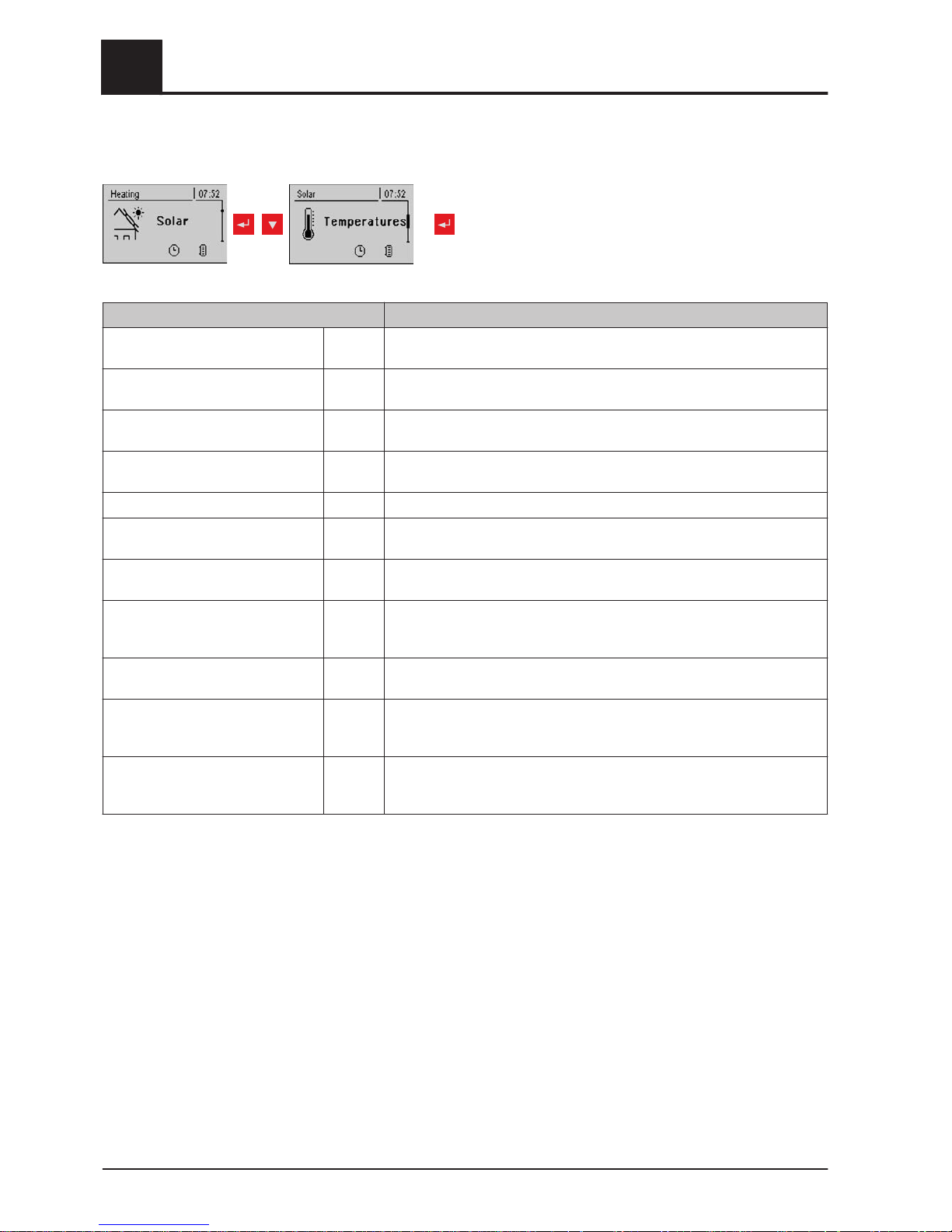
5.3.2 Temperature settings for the solar system
Parameter Description
Boiler target temperature during so‐
lar charging
75°C Up to this temperature the DHW tank is heated by the solar system.
Temp differential to start collector
pump
10°C The collector loading pump activates when the collector temperature ex‐
ceeds the storage or DHW tank temperature by this value.
Temp difference to stop collector
pump
5°C The collector loading pump switches off when the collector temperature
exceeds the storage or DHW tank temperature by this value.
Maximum storage tank bottom tem‐
perature during solar charging
85°C Maximum bottom storage tank temperature at which the collector pump is
switched off (only with storage tank).
Minimum collector temperature 20°C Below this collector temperature the collector pump is switched off.
Heat exchanger - storage tank
pump startup delay
120s Delay for switching on the pump between heat exchanger and storage
tank (only for systems 12, 13).
Heat exchanger - storage tank
pump stop delay
240 s Delay for switching off the pump between heat exchanger and storage
tank (only for system 12, 13).
Storage tank top solar setpoint (fast
loading until this temperature)
60°C Once the top storage tank sensor reaches the set value during solar
charging, the isolating valve switches to bottom storage tank (Only with
systems 12, 13).
Collector - storage tank top differen‐
tial
20°C This is the overcharge for the collector pump controller for the top or bot‐
tom storage tank temperature.
Collector - heat exchanger sec., out‐
feed difference
10°C This parameter specifies how much the heat exchanger secondary out‐
feed should be below the collector temperature. If the temperature is too
low, the speed of the storage tank or DHW tank pump will be reduced.
Collector return - storage tank bot‐
tom differential
20°C Storage tank bottom plus the set value produces the desired temperature
of the collector return. If the collector return is too high, the storage tank
pump speed is reduced.
5
Menu overview and parameters
Menu - Solar
48 Froling GesmbH | A-4710 Grieskirchen, Industriestraße 12 | www.froeling.com
Page 49
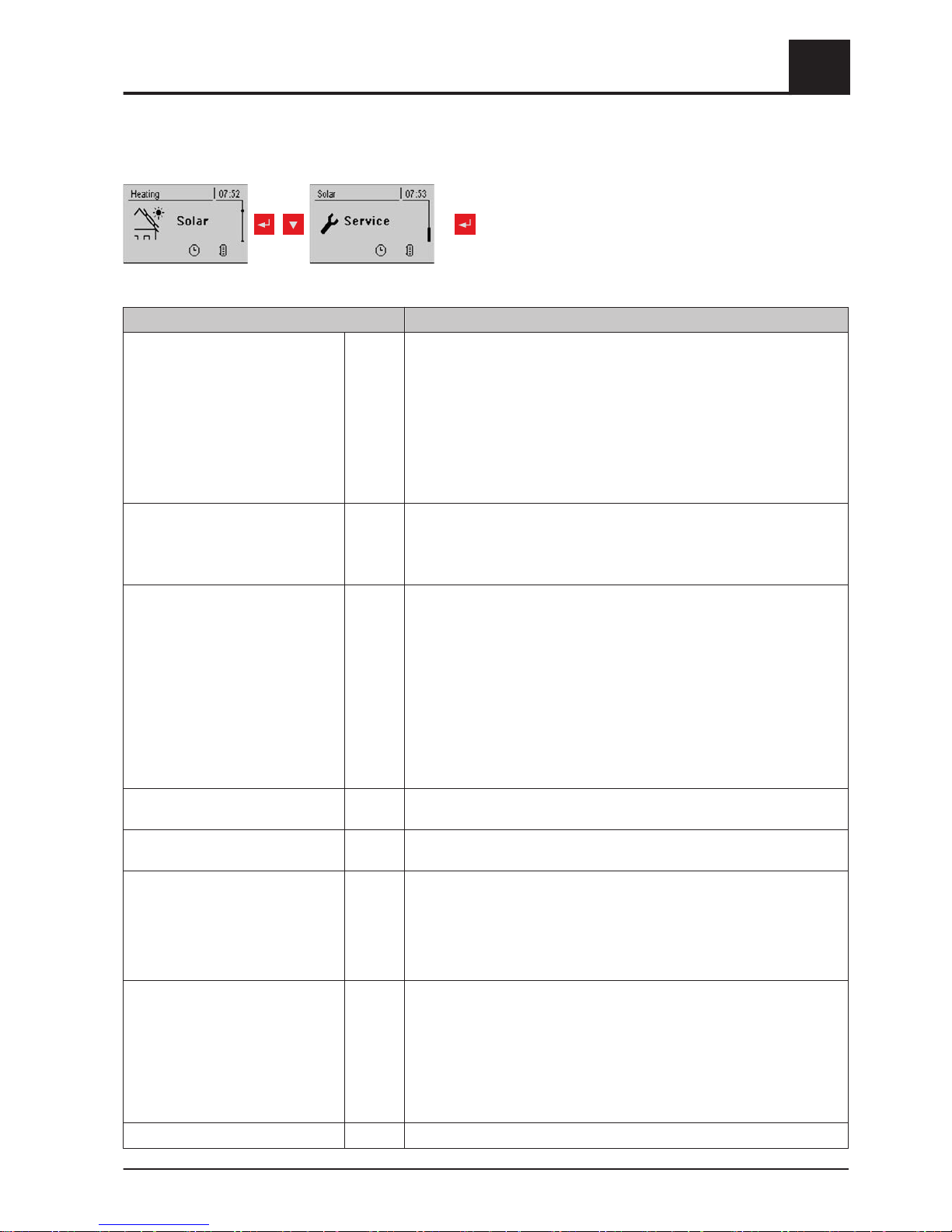
5.3.3 Service parameters of the solar system
repeatedly
Parameter Description
Solar system 1 Specifies the type of solar system. The parameter should be set according
to the solar diagram.
1: Solar panel system only on domestic hot water tank
2: Solar panel system only on storage tank
3: Solar panel system with switch valve (switch from domestic hot water
tank to storage tank, or between top and bottom solar elements with the
H3 hygienic solar layered tank)
Observe the information on the solar panel system in the "
Lambdatronic S
3200 energy systems" documents.
Which pump is used for the solar
collector
1.1 Bus address of the pump that is used.
⇨ See "Setting the module address" [page
20]
Observe the information on the solar panel system in the "Lambdatronic S
3200 energy systems" documents.
PDM setting for solar collector pump Normal
pump
▪ Normal pump
▪
PDM / field pump
▪ PDM / solar pump
▪ PDM field pump + valve
▪ 0 – 10V / field pump
▪ 0 – 10V / solar pump
▪ 0 – 10V field pump + valve
Properties of the respective setting:
⇨ See "PWM / 0 - 10V settings" [page 81]
Minimum collector pump speed 45% Adjustment of the minimum speed to the pump type. (Set the pump mode
according to pump manufacturer’s instructions)
Maximum collector pump speed 100% If you need to limit the maximum speed of the collector pump for systemic
reasons, you can do so by adjusting this parameter.
Collector monitoring → Collector
pump is switched on every 30 min.
for 10 sec
NO If this parameter is active the collector pump is switched on every 30 mi‐
nutes for 10 seconds. If the collector sensor detects an increase in tem‐
perature, the pump is kept on.
This function is active from 10:00am - 7:00pm and the threshold value of
the collector temperature, from which this function is active, is dynamically
adjusted.
For solar to store and DHW tank,
the DHW tank has priority
YES YES: The DHW tank is charged until the temperature setpoint is reached,
and only then is the storage tank supplied.
NO: The DHW tank is charged until the temperature difference between
the collector and the DHW tank is no longer sufficient. When the tempera‐
ture difference has fallen too low, the storage tank is supplied with heat for
20 minutes. Then the collector pump is stopped for 20 minutes and a
check is carried out to see if the temperature difference is now sufficient
for DHW tank charging.
Solar charging to which store 1 Defines the storage tank to which the solar charging takes place.
Menu overview and parameters
5
Menu - Solar
Operating Instructions Lambdatronic S 3200 | B0361214_en 49
Page 50
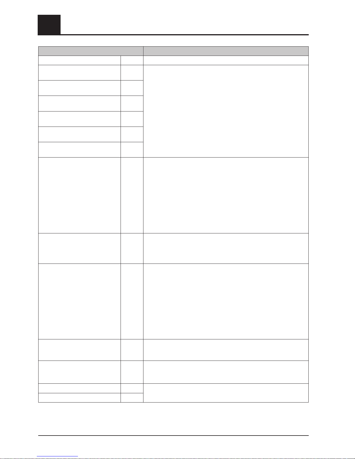
Parameter Description
Solar charging to which DHW tank 1 Defines the DHW tank to which the solar charging takes place.
Which sensor is used for the solar
collector
1.1 Bus addresses of the sensors used, depending on the system
⇨ See "Setting the module address" [page
20]
Observe the information on the solar panel system in the "Lambdatronic S
3200 energy systems" documents.
Which sensor is used for the stor‐
age tank reference
0.2
Which sensor is used for the heat
exchanger sec. flow?
1.4
Which sensor is used for the collec‐
tor return
1.5
Which pump is used for the solar
isolating valve
1.2
Which pump is used for storage
tanks - heat exchanger
2.1
PDM setting for the storage tank heat exchanger pump
Normal
pump
▪ Normal pump
▪
PDM / field pump
▪ PDM / solar pump
▪ PDM field pump + valve
▪ 0 – 10V / field pump
▪ 0 – 10V / solar pump
▪ 0 – 10V field pump + valve
Properties of the respective setting:
⇨ See "PWM / 0 - 10V settings" [page 81]
Which pump is used for DHW tanks
- heat exchanger
2.2 Bus addresses of the sensors used, depending on the system
⇨ See "Setting the module address" [page
20]
Observe the information on the solar panel system in the "Lambdatronic S
3200 energy systems" documents.
PDM setting for the DHW tank heat exchanger pump
Normal
pump
▪ Normal pump
▪
PDM / field pump
▪ PDM / solar pump
▪ PDM field pump + valve
▪ 0 – 10V / field pump
▪ 0 – 10V / solar pump
▪ 0 – 10V field pump + valve
Properties of the respective setting:
⇨ See "PWM / 0 - 10V settings" [page 81]
Invert isolating valve NO For DHW tank loading through the collector, the isolating valve is activated
with 230V. If the valve switches incorrectly, the way it is controlled can be
adjusted using this parameter.
Is a PT1000 sensor used as a solar
sensor?
NO Basic setting for the sensor type used:
NO: Solar sensor - Froling
YES: Sensor PT1000
Collector pump control Kp value 1.00 Control parameter for collector pump
Collector pumps control Tn value 300s
5
Menu overview and parameters
Menu - Solar
50 Froling GesmbH | A-4710 Grieskirchen, Industriestraße 12 | www.froeling.com
Page 51
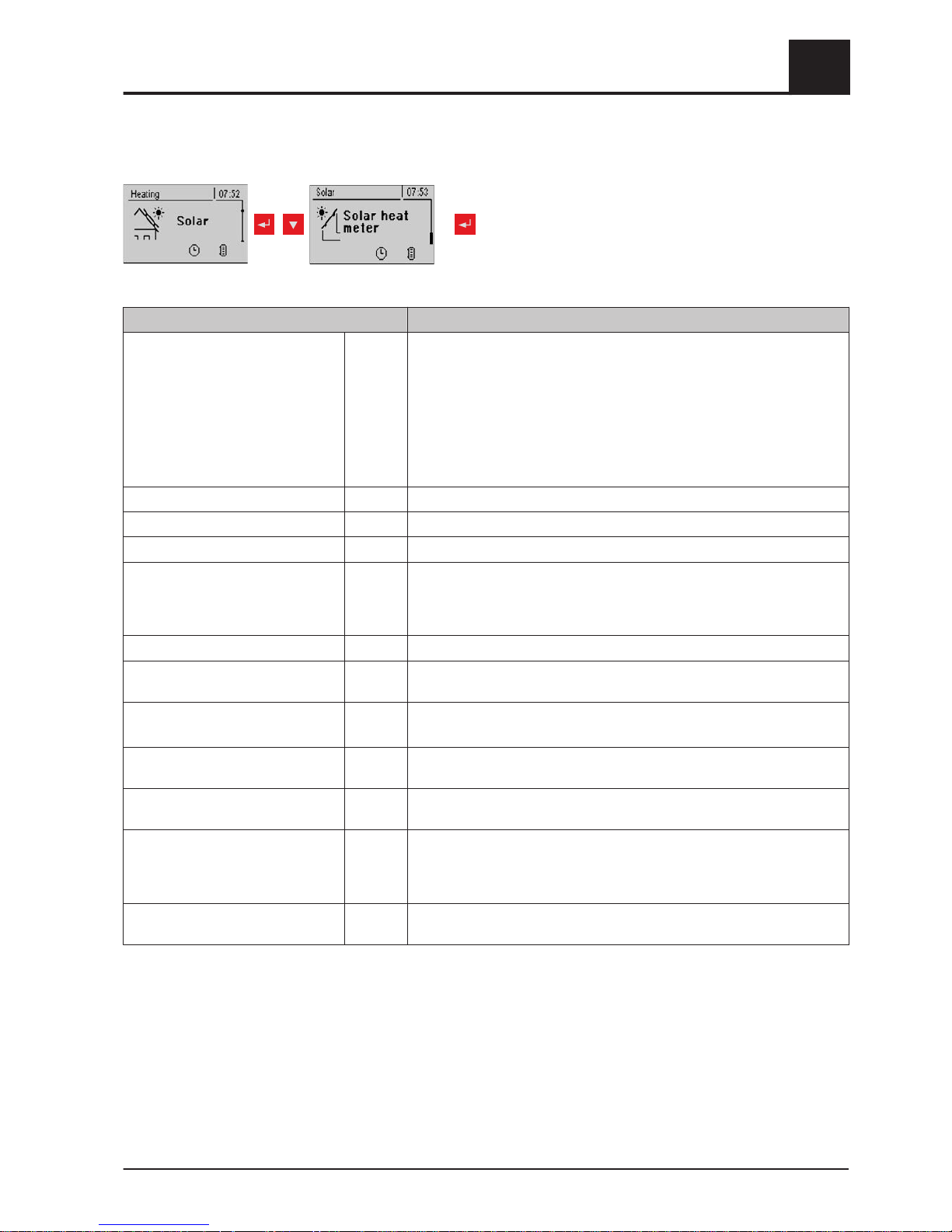
5.3.4 Solar heat meter
repeatedly
Parameter Description
Outfeed: 0 °C / Return: NA
P: 0.0kW / DFL: 0
Today: 0 kWh
Total: 0 kWh
Solar heat meter:
Outfeed: Flow temperature of the solar panel system
Return: Return of the solar panel system
P: Current output of the solar panel system
DFL: Flow-through of the solar panel system
Today: Heat quantity that has been supplied by the solar panel system to‐
day
Total: heat quantity that has been supplied since activation of the solar
panel system
Collector Temperature 80°C Current temperature at collector.
Collector return feed temperature 50°C Current temperature at collector return.
Current output of Solar WMZ [kW] 0.00 Displays current output of solar collector.
DFL Sensor [l/h] 0 Display of the water quantity currently being pumped through the solar
collector.
NOTE: Display is active only if an external volume flow sensor is used and
it has been activated in the controller.
Todays yield [kWh]] 0 Heat quantity that has been supplied by the solar panel system today
Total yield [kWh] 0 Heat quantity that has been supplied since activation of the solar panel
system
Nominal flow of collector pump for
heat meter [L/h]
0 Sets the nominal flow of the collector pump used.
This setting can be ignored if using an external flow meter.
Pulses per litre from the flow sensor 2.0 If an external flow meter is used, adjust this value according to the device
used. [0.5 – 5 pulses/L]
Which sensor is used for the collec‐
tor return
1.5 Bus addresses of the sensors used, depending on the system
⇨ See "Setting the module address" [page
20]
Which sensor is used for heat meter
flow temperature
1.3 If a flow temperature sensor is used for the heat meter in addition to the
collector sensor, set the sensor address accordingly.
Bus addresses of the sensors used, depending on the system
⇨ See "Setting the module address" [page
20]
Is an external flow through counter
used
NO If an external volume flow sensor is used in the collector return, set this
parameter to “YES”.
Menu overview and parameters
5
Menu - Solar
Operating Instructions Lambdatronic S 3200 | B0361214_en 51
Page 52
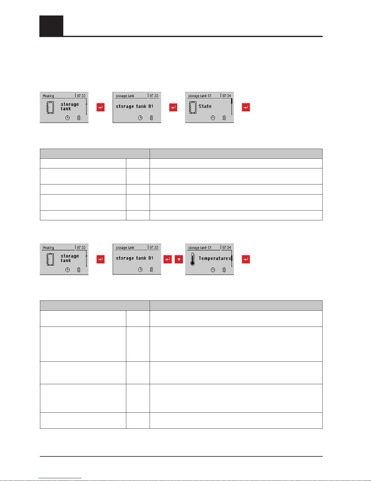
5.4 Menu - Storage tank
5.4.1 Status displays of the storage tank
Storagetank
01...04
Parameter Description
Storage tank top temperature 58°C Current temperature at top storage tank sensor.
Storage tank middle temperature 53°C Current temperature at middle storage tank sensor (depending on configu‐
ration).
Storage tank bottom temperature 50°C Current temperature at bottom storage tank sensor.
Store pump control 50% Specifies the current speed of the storage tank pump as a percentage of
the maximum speed.
Store charge 25% Shows the current storage tank charge.
5.4.2 Temperature settings for the storage tank
Storagetank
01...04
Parameter Description
Heating circuit release from follow‐
ing storage tank temperature
30°C Minimum value of storage tank top temperature for heating circuit release
in combinations with a storage tank
Temperature difference between
boiler and border layer
20°C If the option, "Middle storage tank temperature sensor installed" and the
parameter, "Mid store controller active" have been set to "YES", the con‐
troller attempts keep the temperature of the "middle store" sensor to the
value of the boiler temperature setpoint minus the temperature difference
set here, by regulating the speed of the storage tank pump.
Boiler start if difference between
boiler setpoint and top store is larg‐
er
15°C If the difference between the top store and the boiler setpoint is greater
than the specified value, the boiler starts.
Load storage tank completely if tem‐
perature difference between boiler
and bottom storage tank is lower
than
10°C Temperature difference between boiler and storage tank temperature to
enable storage tank loading.
Top store temp. when the start-up
relief valve switches to bottom store
60°C If the temperature set is exceeded at sensor 0.1 the start relief valve
switches to bottom storage tank
5
Menu overview and parameters
Menu - Storage tank
52 Froling GesmbH | A-4710 Grieskirchen, Industriestraße 12 | www.froeling.com
Page 53

Storage tank charge is 100% at boil‐
er setpoint parameter
4°C 100% storage tank charge is calculated from the specified boiler tempera‐
ture setpoint minus the specified value.
Store charge is 0% at the following
temperature (absolute value)
30°C If the average temperature in the storage tank is less than the specified
value, the storage tank has a charge of 0%.
Menu overview and parameters
5
Menu - Storage tank
Operating Instructions Lambdatronic S 3200 | B0361214_en 53
Page 54
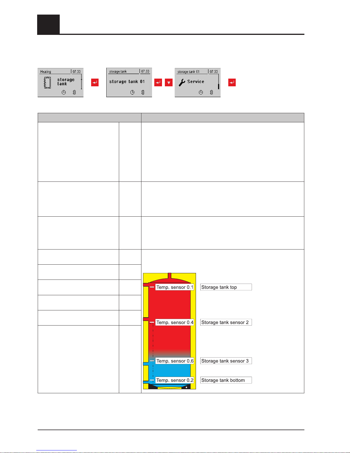
5.4.3 Service parameters of the storage tank
repeatedly
Storagetank
01...04
Parameter Description
Enable heating circuit pump 0 ac‐
cording to top store
NO NO: Release of heating circuit pump 0 from boiler temperature
⇨ See "Temperature settings for the boiler" [page
56]
Parameter "Minimum boiler temperature to release all
pumps".
YES: Release of heating circuit pump 0 from top storage tank temp.
⇨ See "Temperature settings for the storage tank" [page 52]
Parameter "Heating circuit release from following storage
tank temperature"
Residual heat use NO The residual energy is diverted to the DHW tank, the parameter "Pumps
start at" is ignored. The pump is activated at minimum speed until the
boiler temperature is lower than the bottom storage tank temperature +
3°C.
NOTE: Only possible with return temperature control using mixing valve!
Mid store controller active?
If No the sensor is only a display
NO NO
Middle storage tank temperature sensor is used to display the temp.
YES
Middle storage tank temperature sensor is used for the border layer load‐
ing function.
Which sensor is used
for storage tank top
0.1 Parameter display depends on the system.
Observe the information on the hydraulic system in the "
Lambdatronic S
3200 energy systems" documents.
Which sensor is used for storage
tank sensor 2
0.4
Which sensor is used for storage
tank sensor 3
0.6
Which sensor is used for middle
storage tank
0.6
Which sensor is used
for bottom storage tank
0.2
Which pump is used
for the storage tank
0.1
5
Menu overview and parameters
Menu - Storage tank
54 Froling GesmbH | A-4710 Grieskirchen, Industriestraße 12 | www.froeling.com
Page 55
PDM setting for storage tank pump Normal
pump
▪ Normal pump
▪
PDM / field pump
▪ PDM / solar pump
▪ PDM field pump + valve
▪ 0 – 10V / field pump
▪ 0 – 10V / solar pump
▪ 0 – 10V field pump + valve
Properties of the respective setting:
⇨ See "PWM / 0 - 10V settings" [page 81]
Minimum storage tank pump speed 45% Adjustment of the minimum speed to the pump type. (Set the pump mode
according to pump manufacturer’s instructions)
Maximum storage tank pump speed 100% If you need to limit the maximum speed of the storage tank pump for sys‐
temic reasons, you can do so by adjusting this parameter.
Refill calculation active (sensors
have to be assigned correctly)
NO For a recommendation regarding the amount of fuel required to load up
the layered tank to appear on the display when opening the insulated
door, set this parameter to “YES”.
Is a hygienic layered tank used? NO If a hygienic layered tank (combi tank) is used, this parameter must be set
to “YES”.
Volume of storage tank used 2000 L To calculate the amount of firewood required to load the layered tank, en‐
ter the volume of the layered tank installed here.
Pump outlet for store relief valve 8.1 This outlet remains active until an adjustable temperature has been
reached at the top storage tank so that only the top part of the storage
tank needs to be heated. Once this temperature has been reached, the
outlet becomes inactive and the entire store volume is available to the
boiler.
Invert pump outlet for store relief
valve
NO If the valve switches incorrectly, the way it is controlled can be adjusted
using this parameter.
Menu overview and parameters
5
Menu - Boiler
Operating Instructions Lambdatronic S 3200 | B0361214_en 55
Page 56
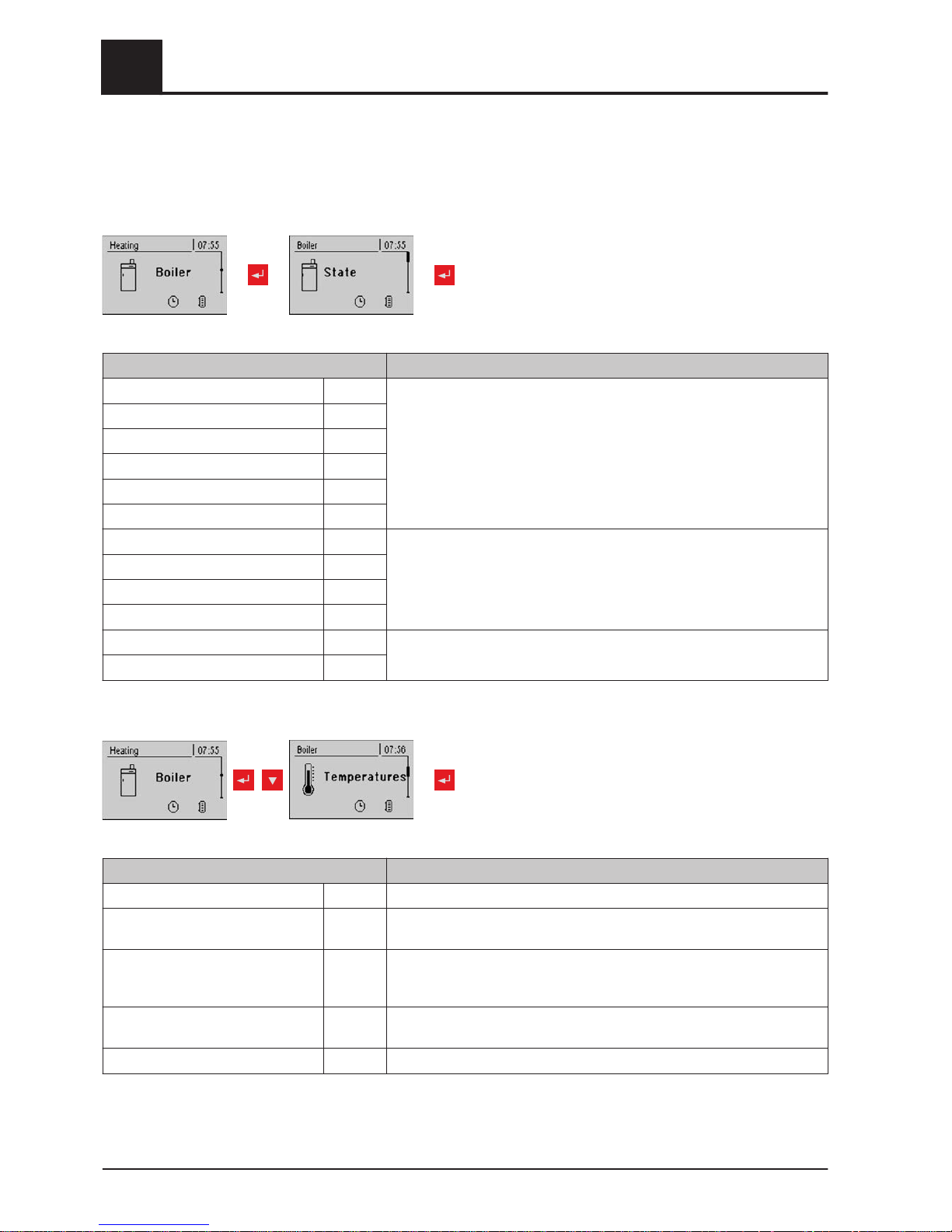
5.5 Menu - Boiler
5.5.1 Status displays for the boiler
Parameter Description
Boiler temperature 80°C Display of the current values for the relevant parameter.
:
:
Flue gas temperature 176°C
Flue gas setpoint 178°C
Boiler control variable 95%
ID fan control 80%
ID fan speed 2350U
Primary air 0%
Position of primary air flap 6%
Secondary air 99%
Position of secondary air flap 95%
Sensor 1 66°C
Return feed sensor 58°C
5.5.2 Temperature settings for the boiler
Parameter Description
Boiler temperature setpoint 80°C The boiler temperature is regulated to this temperature.
Shutdown if current boiler tempera‐
ture is higher than boiler setpoint +
5°C If the boiler temperature exceeds the setpoint by this parameter value, the
boiler switches to “slumber” status.
Always switch off at maximum boiler
setpoint +
3°C If the boiler temperature exceeds the maximum setpoint by this parame‐
ter, the boiler switches to "slumber" status. The heating circuit and store
loading pump will also begin to run to cool the boiler.
Minimum boiler temperature to re‐
lease all pumps
65°C The pumps are activated at this boiler temperature. (Hysteresis 2°C)
Minimum return temperature 60°C The minimum temperature required of the return to the boiler.
5
Menu overview and parameters
Menu - Boiler
56 Froling GesmbH | A-4710 Grieskirchen, Industriestraße 12 | www.froeling.com
Page 57
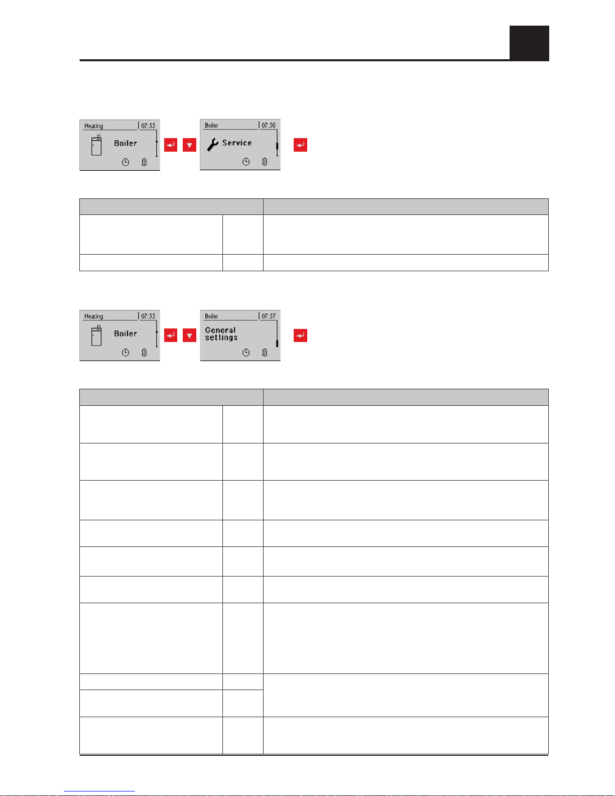
5.5.3 Service parameters of the boiler
repeatedly
Parameter Description
Mixer runtime 240 s Set mixer runtime of the mixer in use.
❒
Recommendation to reduce mixer vibration
Do not set to < 150 s
Output fire off message using HKP0 NO If the boiler changes to "Off" status, the HKP0 output is closed.
5.5.4 General settings
repeatedly
Parameter Description
Very dry material (w < 15%) param‐
eter adopt next line
NO If this parameter is set to "YES" and then the parameter “Adopt boiler
standard values” is set to “YES”, the parameters are automatically
adjusted for very dry firewood.
Adopt boiler standard values NO If this parameter is set to "YES", the current parameters for the selected
boiler are set. After the values have been adopted the parameter jumps to
"NO”.
Abort heating up --> ID fan off, close
air flaps
NO If this parameter is set to “YES”, the boiler heating up process can be
aborted.
NOTE: Criteria for “Off” status must be fulfilled.
Modem installed NO If the boiler has a modem for data transfer, this value must be set to
"YES".
Memory cycle of data logger 5 s Do not change this value!
This is the memory cycle used for saving data onto the data logger.
Send a line break when ASCII data
output on COM2
NO
COM 2 is used as a MODBUS inter‐
face
NO YES:
The COM 2 interface can be used for connection with a MODBUS (RTU /
ASCII)
NO:
The COM 2 interface sends the most important boiler values every sec‐
ond
MODBUS address 2 Adjustable parameters for MODBUS
MODBUS protocol
(1 – RTU / 2 – ASCII)
1
Set hours since last maintenance to0NO To reset the counter “Hours since last maintenance”, this parame‐
ter must be set to "YES”. After the has been reset, the parameter jumps to
"NO”.
Menu overview and parameters
5
Menu - Boiler
Operating Instructions Lambdatronic S 3200 | B0361214_en 57
Page 58
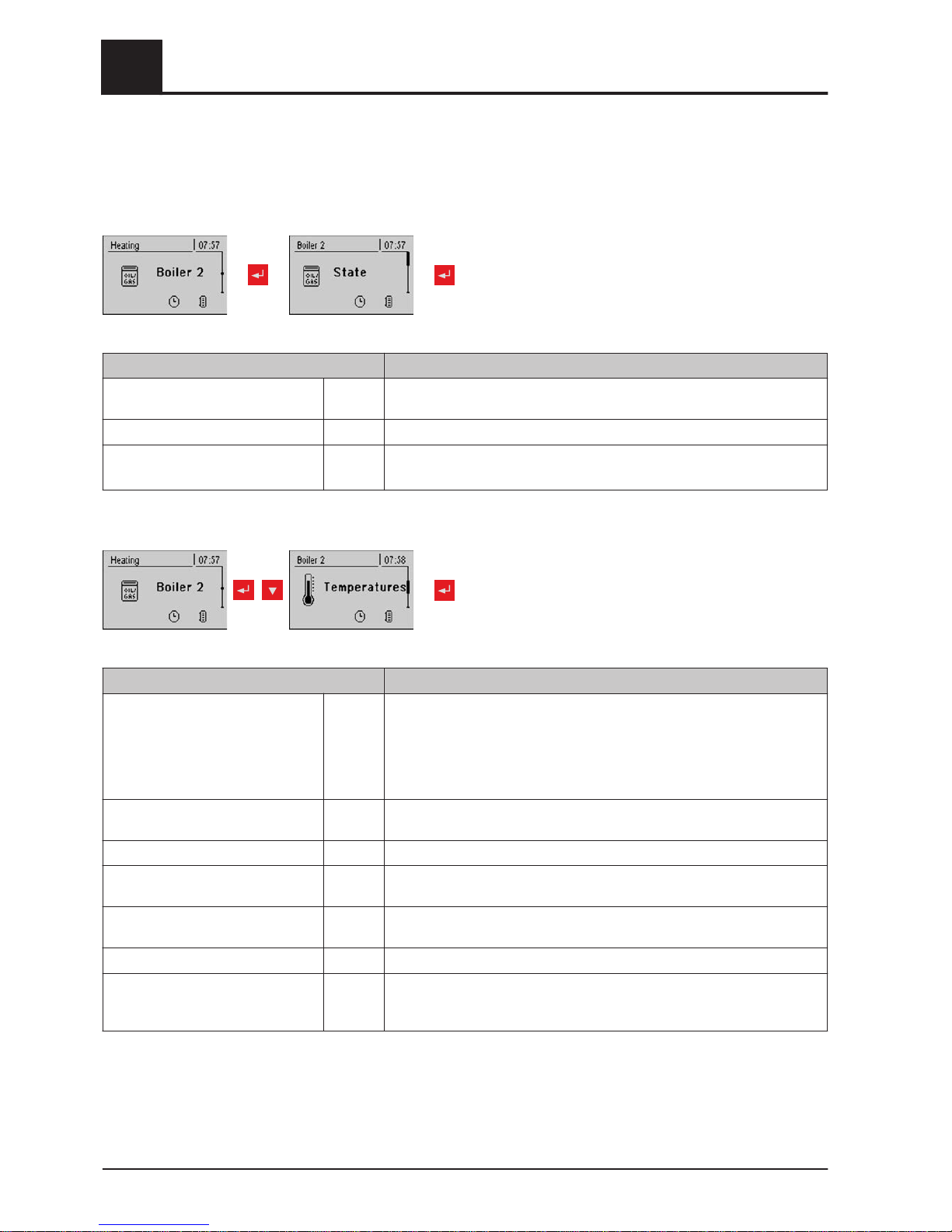
5.6 Menu - Boiler 2
5.6.1 Status displays for the secondary boiler
Parameter Description
Temperature of
standby boiler
23°C Display of the current temperature of the standby boiler
Burner relay status 0 Shows the current status of the burner relay
Manual start of standby boiler
(only when ID fan is switched off)
OFF When the parameter is activated the standby boiler starts.
Warning! Burner blockage noted.
5.6.2 Temperature settings of the secondary boiler
Parameter Description
Standby boiler start delay 10 m Start delay of the burner relay if the boiler fails (the boiler status is off, fault
or shut down and the boiler temperature is 5°C below the setpoint). In
storage mode the burner relay, however, only comes on when the storage
tank has cooled down.
(Top storage tank temperature is lower than the highest required tempera‐
ture)
Standby boiler start, if storage tank
top temperature is below
20°C Temperature at the top of the storage tank, which the temperature must
fall below for the standby boiler to be activated
Standby boiler minimum runtime 5 m Standby boiler minimum runtime
Minimum temperature of standby
boiler
55°C Minimum temperature of the standby boiler for release of standby boiler
unloading output.
Temperature difference between
standby boiler and storage tank
10°C Minimum temperature difference between standby boiler and storage tank,
which releases secondary boiler unloading output.
Oil valve shut delay 30s The switching back of the isolating valve is delayed by the specified time.
Standby boiler delivery temperature 95°C If the standby boiler exceeds the specified temperature, the isolating valve
switches and skims the boiler
(only with hydraulic system 3)
5
Menu overview and parameters
Menu - Boiler 2
58 Froling GesmbH | A-4710 Grieskirchen, Industriestraße 12 | www.froeling.com
Page 59
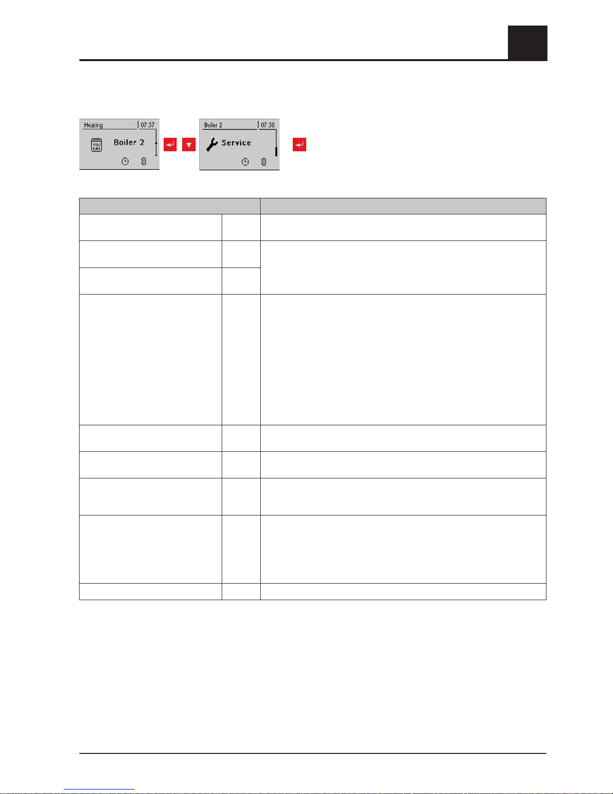
5.6.3 Service parameters for secondary boiler
repeatedly
Parameter Description
Control standby boiler variably to
the target value
YES If the standby boiler has no independent control, the main control takes
over control of the boiler setpoints of the secondary boiler.
Which sensor is used for standby
boiler
0.5 Bus address of the sensor used.
⇨ See "Setting the module address" [page
20]
Observe the information on hydraulic systems in the "Lambdatronic S
3200 energy systems" documents.
Which output is used for unloading
standby boiler
Pump 1
PDM setting for solar collector pump Normal
pump
▪ Normal pump
▪
PDM / field pump
▪ PDM / solar pump
▪ PDM field pump + valve
▪ 0 – 10V / field pump
▪ 0 – 10V / solar pump
▪ 0 – 10V field pump + valve
Properties of the respective setting:
⇨ See "PWM / 0 - 10V settings" [page 81]
Minimum speed of boiler 2 pump 45% Adjustment of the minimum speed to the pump type. (Set the pump mode
according to pump manufacturer’s instructions)
Maximum speed of boiler 2 pump 100% If you need to limit the maximum speed of the boiler 2 pump for systemic
reasons, you can do so by adjusting this parameter.
Invert standby boiler isolating valve NO For DHW tank loading through the standby boiler, the isolating valve is ac‐
tivated with 230V. If the valve switches incorrectly, this parameter can be
adjusted.
Which second boiler is installed? Oil boil‐erBoiler type of the secondary boiler:
- OIL BOILER
- GAS HEATER
- MANUALLY FED
- AUT. FED
- GAS BOILER
Burner relays A 0
Menu overview and parameters
5
Menu - Boiler 2
Operating Instructions Lambdatronic S 3200 | B0361214_en 59
Page 60
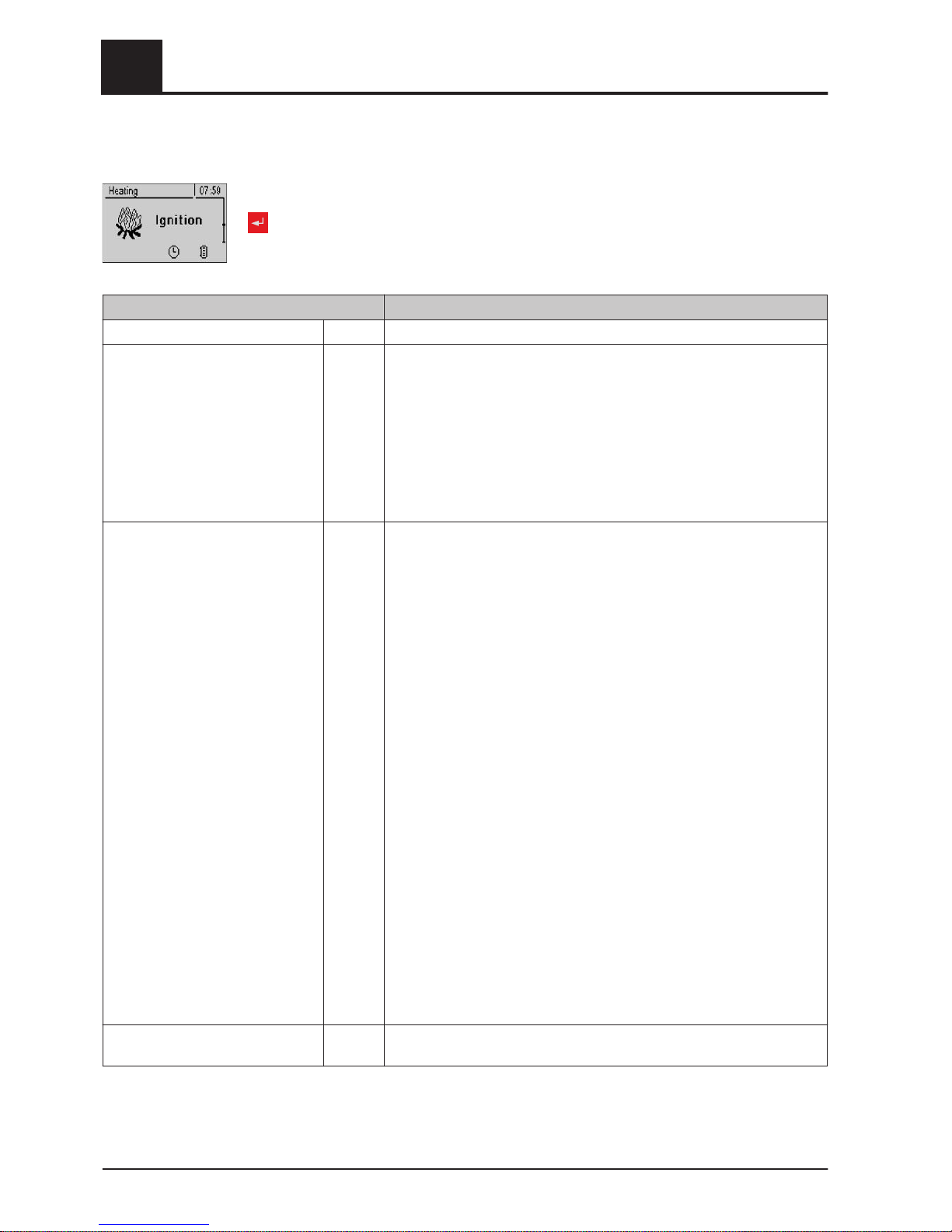
5.7 Menu - Ignition
Parameter Description
Automatic Ignition YES Parameter for switching automatic ignition on/off
Start ignition Date
and time
Determines how ignition takes place
▪ Date and time: see parameter "Ignition time"
▪ In approx. 15 min: ignition takes place immediately after “Preventila‐
tion” status
▪ Ext. release: If the boiler release contact is closed at the core module,
ignition starts
▪ Buffer tank min: see parameter "Ignition time"
▪ Storage tank < outfeed max: see parameter "Ignition time"
Ignition time (date - time) 05/10 –
20:00
Day (date or daily) and time setting for the start of ignition. The parameter
is only active when the “Start ignition“ parameter is set to “Date and
time”, “Buffer tank min” or "Buffer < f.flow".
NOTICE! The specified date must not be more than two calendar months
in the future and not more than two months in the past!
NOTICE! The boiler status must generally be “Ignition wait" for ignition to
start. Follow the instructions for heating up with the automatic ignition.
⇨ See "Heating up with automatic ignition" [page
33]
“Date and time” method:
Ignition starts at the specified time exactly. If the parameter is set to “daily”
instead of the date, ignition starts every day at the specified time.
“Buffer tank min” method:
The ignition process starts if heat is requested from the storage tank from
the specified time (parameter "Boiler start if difference be-
tween boiler setpoint and top store is larger”). The peri‐
od applies from the specified time until 24:00 h on the specified date. If the
specified time is not subsequently changed and ignition is not disabled,
the store loading criterion applies daily from the specified time.
"Buffer < f.flow” method:
The maximum flow temperature required by the system environment (e.g.
heating circuit) is compared with the current storage tank temperature
from the specified time. If the top storage tank temperature falls below the
maximum flow temperature setpoint, the ignition process starts. The peri‐
od applies from the specified time until 24:00 h on the specified date. If the
specified time is not subsequently changed and ignition is not disabled,
the start criterion applies daily from the specified time.
Maximum ign. duration 15 m Specifies how long the ignition procedure should last. "Heating" status
must be reached within this time.
5
Menu overview and parameters
Menu - Network pump
60 Froling GesmbH | A-4710 Grieskirchen, Industriestraße 12 | www.froeling.com
Page 61
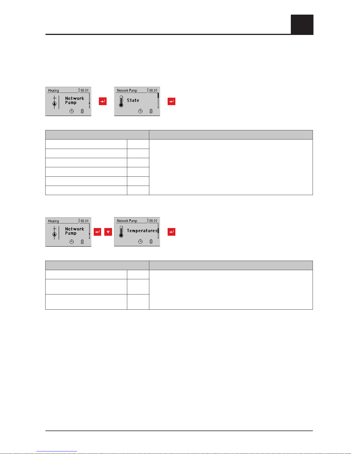
5.8 Menu - Network pump
5.8.1 Status display of the network pump
Parameter Description
Network return temperature 40°C Display of the current values for the relevant parameter. Position of the
sensors and pumps depending on the system used:
Note the information on multiple house diagrams in the “
Lambdatronic S
3200 energy systems" documents.
Network pump speed 60%
Return temperature feeder 1 0°C
Speed, feeder 1 0%
Return temperature feeder 2 0°C
Speed, feeder pump 2 0%
5.8.2 Network pump temperature settings
Parameter Description
Network return temperature setpoint 50°C Settings for the desired network temperature setpoints. Position of the
sensors depending on the system used:
Note the information on multiple house diagrams in the “
Lambdatronic S
3200 energy systems" documents.
Return temperature setpoint
at feeder 1
50°C
Return temperature setpoint
at feeder 2
50°C
Menu overview and parameters
5
Menu - Network pump
Operating Instructions Lambdatronic S 3200 | B0361214_en 61
Page 62
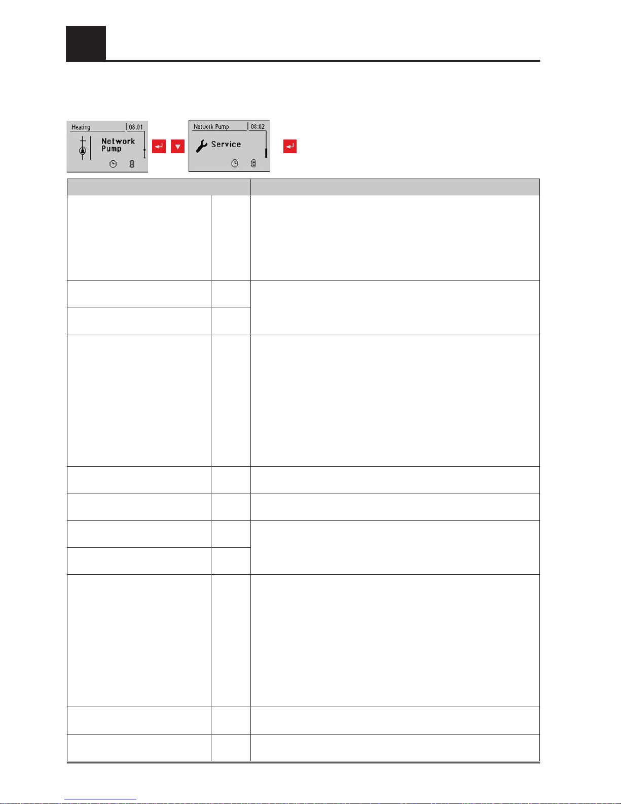
5.8.3 Service parameters for the network pump
Parameter Description
Only switch on the
network pump when required by the
store
(variant 3 / 4 only)
NO YES:
The network pump switches on, if there is a requirement from a storage
tank.
NO:
The network pump switches on, if there is a requirement from a storage
tank, a DHW tank or a heating circuit.
With variant 3 only storage tanks 2, 3 and 4 are considered.
Which sensor is used
for the network return temperature
0.6 Bus addresses of the sensors used, depending on the system
⇨ See "Setting the module address" [page
20]
Observe the information on hydraulic systems in the "Lambdatronic S
3200 energy systems" documents.
Which pump is used for the
network pump
0.2
PWM setting for network pump Normal
pump
▪ Normal pump
▪
PWM / field pump
▪ PWM / solar pump
▪ PWM field pump + valve
▪ 0 – 10V / field pump
▪ 0 – 10V / solar pump
▪ 0 – 10V field pump + valve
Properties of the respective setting:
⇨ See "PWM / 0 - 10V settings" [page 81]
Minimum speed of network pump 45% Adjustment of the minimum speed to the pump type. (Set the pump mode
according to pump manufacturer’s instructions)
Maximum speed for network pump 100% If you need to limit the maximum speed of the storage tank pump for sys‐
temic reasons, you can do so by adjusting this parameter.
Which sensor is used for
feeder 1
1.6 Bus addresses of the sensors used, depending on the system
⇨ See "Setting the module address" [page
20]
Observe the information on hydraulic systems in the "Lambdatronic S
3200 energy systems" documents.
Which pump is used for
feeder 1
1.1
PWM setting for feeder pump 1 Normal
pump
▪ Normal pump
▪
PWM / field pump
▪ PWM / solar pump
▪ PWM field pump + valve
▪ 0 – 10V / field pump
▪ 0 – 10V / solar pump
▪ 0 – 10V field pump + valve
Properties of the respective setting:
⇨ See "PWM / 0 - 10V settings" [page 81]
Minimum speed for feeder pump 1 45% Adjustment of the minimum speed to the pump type. (Set the pump mode
according to pump manufacturer’s instructions)
Maximum speed for feeder pump 1 100% If you need to limit the maximum speed of the storage tank pump for sys‐
temic reasons, you can do so by adjusting this parameter.
5
Menu overview and parameters
Menu - Network pump
62 Froling GesmbH | A-4710 Grieskirchen, Industriestraße 12 | www.froeling.com
Page 63
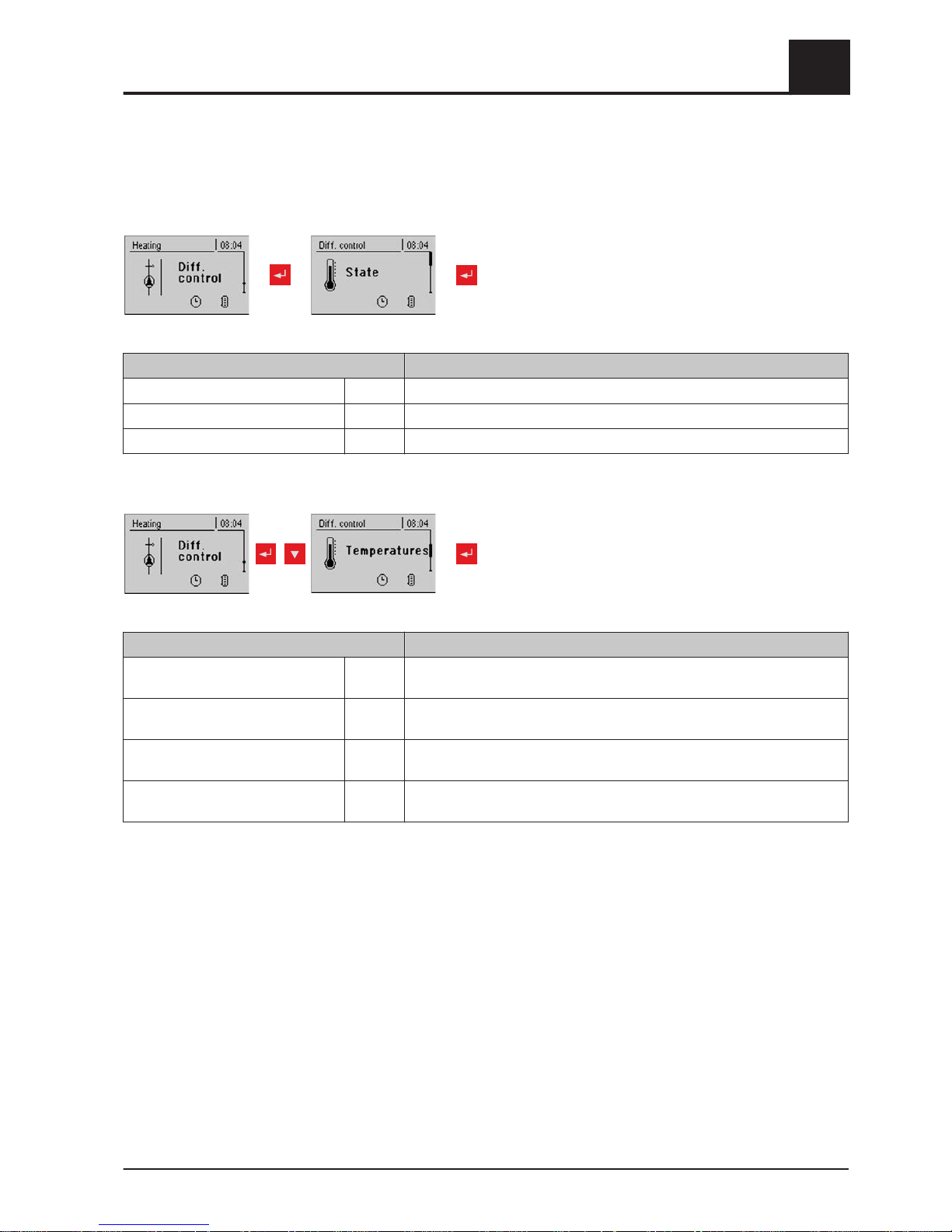
5.9 Menu – Diff. control
5.9.1 Status displays for the diff. control
Parameter Description
Heat source sensor 70°C Current temperature of the heat source (heat distributor, e.g. storage tank)
Heat sink sensor 60°C Current temperature of the heat sink (user, e.g. DHW tank)
Pump speed 45% Current pump speed
5.9.2 Temperature settings for the diff. control
Parameter Description
Startup difference 10°C If the temperature difference between the heat source and the heat sink
exceeds this value, the pump activates
Shutdown difference 5°C If the temperature difference between the heat source and the heat sink
falls below this value, the pump is deactivated.
Minimum temperature for heat
source
10°C Temperature settings for regulating range of the differential temperature
regulating output.
Maximum temperature for
heat sink
100°C The standard settings of 10°C or 100°C are selected so that the values in
normal operation stay outside a limit.
Menu overview and parameters
5
Menu – Diff. control
Operating Instructions Lambdatronic S 3200 | B0361214_en 63
Page 64
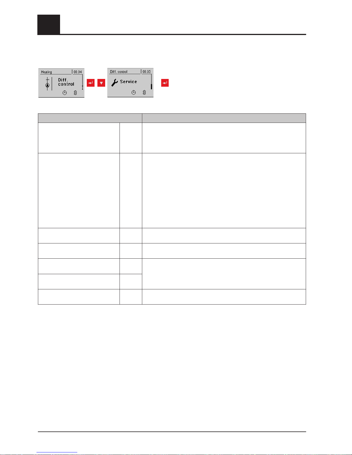
5.9.3 Service parameters for the diff. control
repeatedly
Parameter Description
Which pump is
used
7.2 Bus addresses of the sensors used, depending on the system
⇨ See "Setting the module address" [page
20]
Observe the information on hydraulic systems in the "Lambdatronic S
3200 energy systems" documents.
PDM setting for diff. controller pump Normal
pump
▪ Normal pump
▪
PDM / field pump
▪ PDM / solar pump
▪ PDM field pump + valve
▪ 0 – 10V / field pump
▪ 0 – 10V / solar pump
▪ 0 – 10V field pump + valve
Properties of the respective setting:
⇨ See "PWM / 0 - 10V settings" [page 81]
Minimum
pump speed
45% Adjustment of the minimum speed to the pump type. (Set the pump mode
according to pump manufacturer’s instructions)
Maximum pump speed 100% If you need to limit the maximum speed of the diff. controller pump for sys‐
temic reasons, you can do so by adjusting this parameter.
Which sensor is used for the
heat source
7.5 Bus addresses of the sensors used, depending on the system
⇨ See "Setting the module address" [page
20]
Observe the information on hydraulic systems in the "Lambdatronic S
3200 energy systems" documents.
Which sensor is used for the
heat sink
7.6
Sensor monitoring YES If relatively low temperatures (< 5°C) occur when using the diff. controller,
setting the parameter to “NO” suppresses the error message
5
Menu overview and parameters
Menu – Diff. control
64 Froling GesmbH | A-4710 Grieskirchen, Industriestraße 12 | www.froeling.com
Page 65
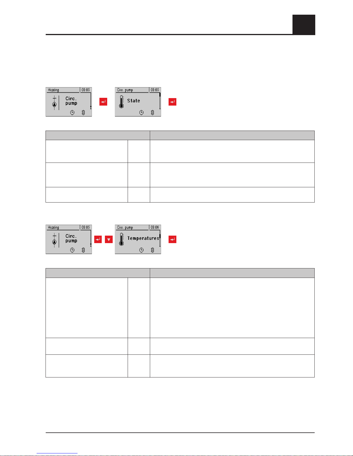
5.10 Menu - Circulation pump
5.10.1 Status display for the circulation pump
Parameter Description
Return temperature in
circulation line
45°C Shows the current temperature at the return sensor of the circulation line.
If the parameter "Return sensor present" is set to "NO", 0°C is permanent‐
ly displayed.
Flow switch on the
domestic hot water line
1 Shows the current status of the flow sensor.
0 ... No flow at the valve
1 ... Valve registers flow
Speed of the
circulation pump
100% Current circulation pump speed
5.10.2 Temperature settings for the circulation pump
Parameter Description
Is a return sensor (present)? YES YES:
The circulation pump is controlled according to time program and temper‐
ature at the sensor. In conjunction with the use of a flow valve, the circula‐
tion pump is also activated at a signal from the flow valve.
NO:
The circulation pump is controlled according to time program. In conjunc‐
tion with the use of a flow valve, the circulation pump is also activated at a
signal from the flow valve.
Connect the flow sensor as the return sensor!
Switch off the pump at what return
temperature in the circulation line
50°C Parameter only relevant when a return sensor is used!
If the set temperature is reached, the circulation pump shuts down.
Circulation pump run-on 300s Parameter only when a flow valve is used!
If the flow valve does not register any more flow, the circulation pump car‐
ries on running for the time set.
Menu overview and parameters
5
Menu - Circulation pump
Operating Instructions Lambdatronic S 3200 | B0361214_en 65
Page 66
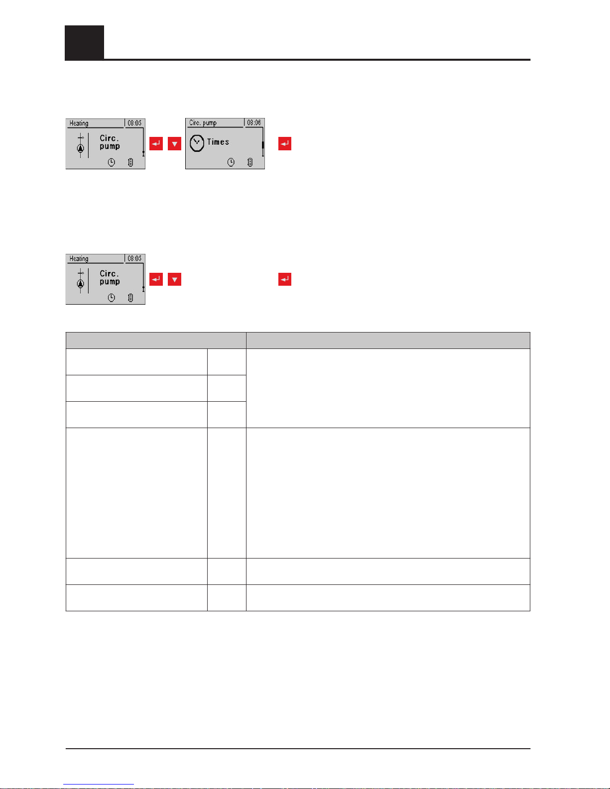
5.10.3 Time settings for the circulation pump
repeatedly
⇨ See "Setting times" [page 35]
5.10.4 Service parameters of the circulation pump
repeatedly
Parameter Description
Which sensor is used for the
circulation return
0.6 Bus addresses of the sensors and pumps used, depending on the system
⇨ See "Setting the module address" [page
20]
Observe the information on hydraulic systems in the "Lambdatronic S
3200 energy systems" documents.
Which sensor input is used for the
flow switch
1.5
Which pump is used for the circula‐
tion
3.1
PWM settings for the circulation
pump
Normal
pump
▪ Normal pump
▪
PWM / field pump
▪ PWM / solar pump
▪ PWM field pump + valve
▪ 0 – 10V / field pump
▪ 0 – 10V / solar pump
▪ 0 – 10V field pump + valve
Properties of the respective setting:
⇨ See "PWM / 0 - 10V settings" [page 81]
Minimum speed of the circulation
pump
45% Adjustment of the minimum speed to the pump type. (Set the pump mode
according to pump manufacturer’s instructions)
Maximum speed of the circulation
pump
100% If you need to limit the maximum speed of the circulation pump for system‐
ic reasons, you can do so by adjusting this parameter.
5
Menu overview and parameters
Menu - Circulation pump
66 Froling GesmbH | A-4710 Grieskirchen, Industriestraße 12 | www.froeling.com
Page 67
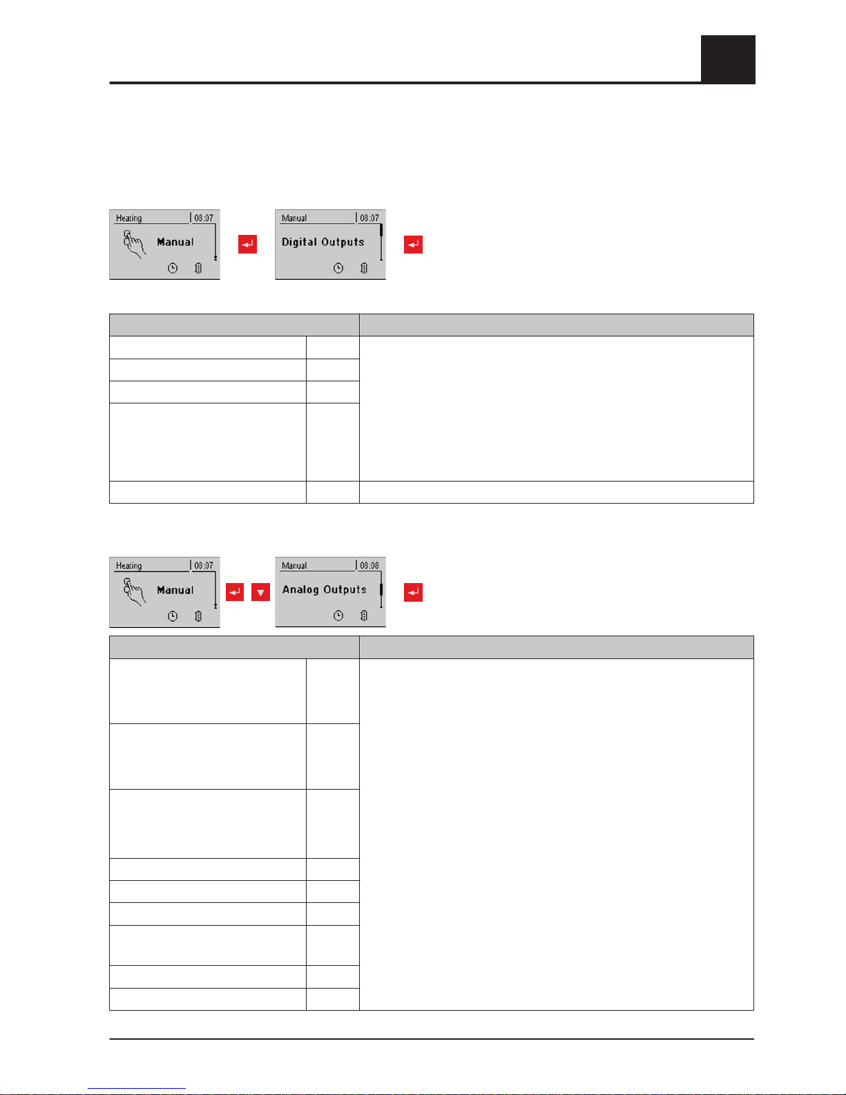
5.11 Menu - Manual
5.11.1 Digital outputs
Parameter Description
Heating Circuit 1 Mixer OPEN A 0 Used to test the digital outputs and is intended only for service techni‐
cians. The parameters displayed vary depending on the configuration
A … automatic
-A 0 … automatic, OFF
-A 1 … automatic, ON
0 … MANUAL, OFF
1 … MANUAL, ON
Heating Circuit 1 Mixer CLOSED A 0
Lambda probe heating A 0
Heating circuit pump 0 A 0
Valve for condenser A 0
5.11.2 Analogue outputs
Parameter Description
Primary air Actual
value:
20%
A 18%
Used to test the analogue outputs and is intended only for service techni‐
cians. The parameters displayed vary depending on the configuration
A … automatic
-A 0% … automatic, OFF
-A 1% - 100% … automatic, with % value ON
0% … manual, OFF
1% - 100% ... manual, with corresponding % value ON
Secondary air Actual
value:
5%
A 5%
ID Fan Actual
value: 0
rpm
A 0%
Pump 1 on core module A 0%
Pump 0.1 A 0%
Pump 0.2 A 0%
:
:
Pump 7.1 A 0%
Pump 7.2 A 0%
Menu overview and parameters
5
Menu - Manual
Operating Instructions Lambdatronic S 3200 | B0361214_en 67
Page 68
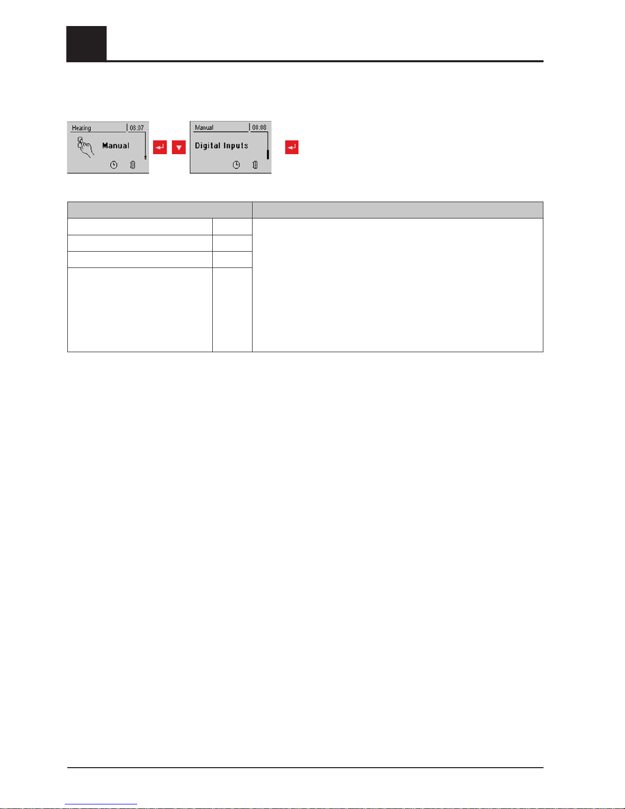
5.11.3 Digital inputs
repeatedly
Parameter Description
Door switch A 0 Used to test the digital inputs and intended only for service technicians.
The parameters displayed vary depending on the configuration.
A … Automatic
-A 0 … Automatic, OFF
-A 1 … Automatic, ON
0... Manual, OFF
1 ... Manual, ON
Hi-limit stat input A 0
E-stop input A 0
Boiler enable A 0
5
Menu overview and parameters
Menu - Manual
68 Froling GesmbH | A-4710 Grieskirchen, Industriestraße 12 | www.froeling.com
Page 69
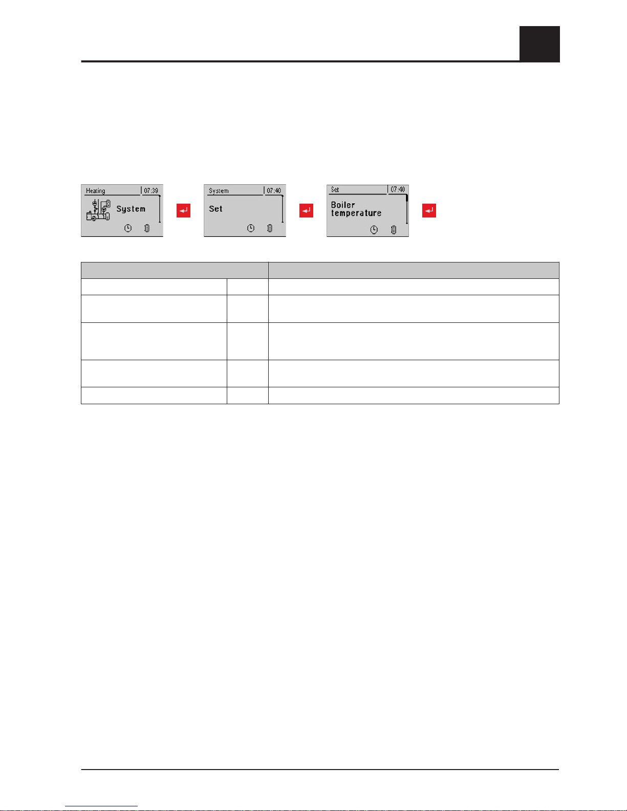
5.12 Menu - System
5.12.1 Settings
Setting parameters – Boiler temperature
Parameter Description
Boiler temperature setpoint 80°C The boiler temperature is regulated to this temperature.
Shutdown if current boiler tempera‐
ture is higher than boiler setpoint +
5°C If the boiler temperature exceeds the setpoint by this parameter value, the
boiler switches to “slumber” status.
Always switch off at maximum boiler
setpoint +
3°C If the boiler temperature exceeds the maximum setpoint by this parame‐
ter, the boiler switches to "slumber" status. The heating circuit and store
loading pump will also begin to run to cool the boiler.
Minimum boiler temperature to re‐
lease all pumps
65°C The pumps are activated at this boiler temperature. (Hysteresis 2°C)
Minimum return temperature 60°C The minimum temperature required of the return to the boiler.
Menu overview and parameters
5
Menu - System
Operating Instructions Lambdatronic S 3200 | B0361214_en 69
Page 70
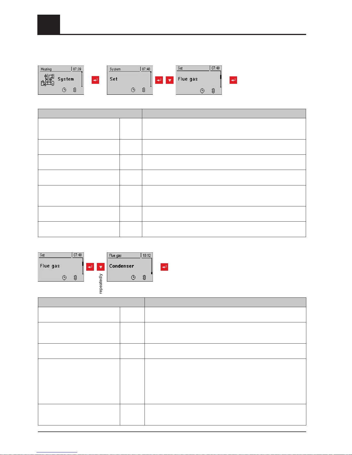
Adjustable parameters – Flue gas
Parameter Description
Maximum heating up time, during
which HEATING status must be
reached
10m
Minimum flue gas temperature 120°C Min. setpoint for the flue gas temperature. Lowest load point for continu‐
ous operation
Max. flue gas temperature 250°C Max. setpoint for the flue gas temperature. Highest load point for suffi‐
ciently good level of efficiency.
Start increase of flue gas tempera‐
ture
20°C Value, by which the flue gas temperature setpoint is increased when heat‐
ing up.
Minimum difference between flue
gas temperature and boiler temper‐
ature in HEATING
15°C Condition for "Heating" status
Flue gas temperature, below which
boiler switches to OFF status
80°C If the flue gas temperature is below this value for the duration of the maxi‐
mum heating up time, the boiler switches to "Off" status.
Desired work point of flue gas tem‐
perature
180°C
Calorific value HE
Parameter Description
Calorific value heat exchanger
installed
NO If this parameter is set to "YES", the cleaning program is activated for the
calorific value heat exchanger.
Calorific value heat exchanger
Cleaning interval
(Heating hours)
30 h Specifies the number of heating hours after which the calorific value heat
exchanger is cleaned.
Calorific value heat exchanger
Cleaning duration
60 s Specifies the duration of the cleaning.
On-time of spray valve.
Overall cycle 20 sec
100% The entire cleaning process is set with the “Calorific value heat
exchanger cleaning duration” parameter. The cleaning time is
regarded as the time in which the spray valve is active. Pause times
(spray valve off) are not included in the cleaning time.
Example:
100% = spray valve active for the specified time
75% = spray valve active for 15 sec and 5 sec pause
Flue gas condenser
Heating: 0 min
Washing processes: 0
Shows the current values.
5
Menu overview and parameters
Menu - System
70 Froling GesmbH | A-4710 Grieskirchen, Industriestraße 12 | www.froeling.com
Page 71
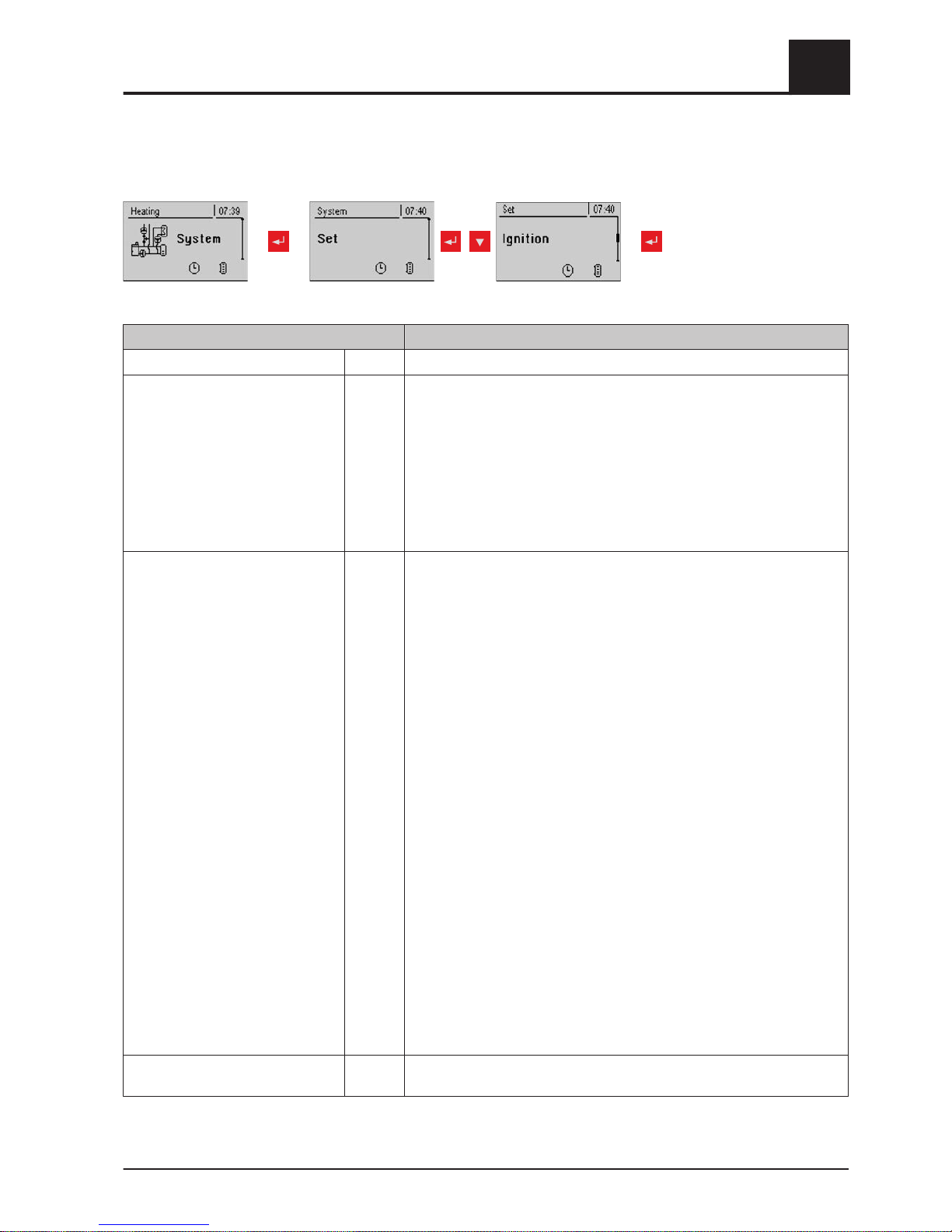
Adjustable parameters – Ignition
repeatedly
Parameter Description
Automatic Ignition YES Parameter for switching automatic ignition on/off
Start ignition Date
and time
Determines how ignition takes place
▪ Date and time: see parameter "Ignition time"
▪ In approx. 15 min: ignition takes place immediately after “Preventila‐
tion” status
▪ Ext. release: If the boiler release contact is closed at the core module,
ignition starts
▪ Buffer tank min: see parameter "Ignition time"
▪ Storage tank < outfeed max: see parameter "Ignition time"
Ignition time (date - time) 05/10 –
20:00
Day (date or daily) and time setting for the start of ignition. The parameter
is only active when the “Start ignition“ parameter is set to “Date and
time”, “Buffer tank min” or "Buffer < f.flow".
NOTICE! The specified date must not be more than two calendar months
in the future and not more than two months in the past!
NOTICE! The boiler status must generally be “Ignition wait" for ignition to
start. Follow the instructions for heating up with the automatic ignition.
⇨ See "Heating up with automatic ignition" [page
33]
“Date and time” method:
Ignition starts at the specified time exactly. If the parameter is set to “daily”
instead of the date, ignition starts every day at the specified time.
“Buffer tank min” method:
The ignition process starts if heat is requested from the storage tank from
the specified time (parameter "Boiler start if difference be-
tween boiler setpoint and top store is larger”). The peri‐
od applies from the specified time until 24:00 h on the specified date. If the
specified time is not subsequently changed and ignition is not disabled,
the store loading criterion applies daily from the specified time.
"Buffer < f.flow” method:
The maximum flow temperature required by the system environment (e.g.
heating circuit) is compared with the current storage tank temperature
from the specified time. If the top storage tank temperature falls below the
maximum flow temperature setpoint, the ignition process starts. The peri‐
od applies from the specified time until 24:00 h on the specified date. If the
specified time is not subsequently changed and ignition is not disabled,
the start criterion applies daily from the specified time.
Maximum ign. duration 15 m Specifies how long the ignition procedure should last. "Heating" status
must be reached within this time.
Menu overview and parameters
5
Menu - System
Operating Instructions Lambdatronic S 3200 | B0361214_en 71
Page 72
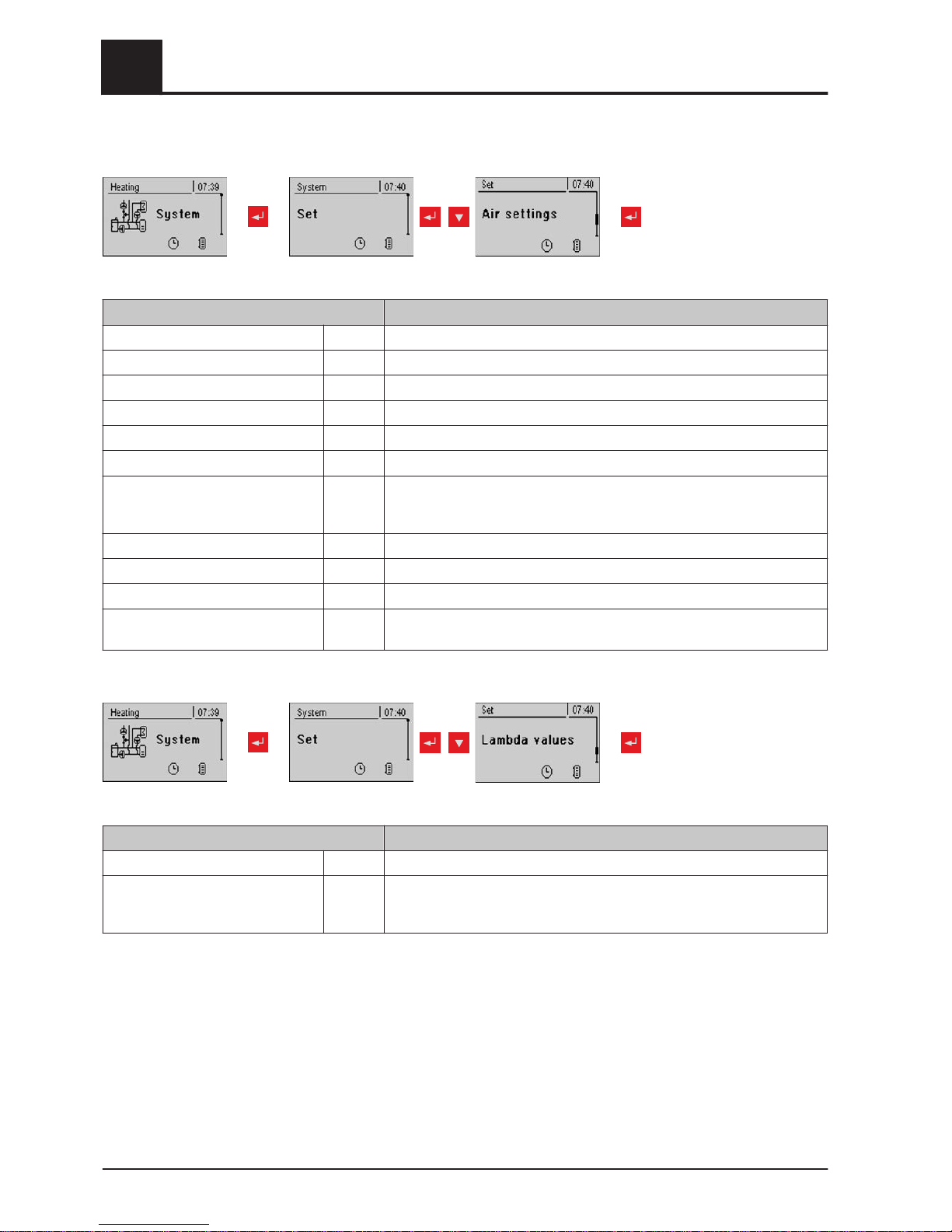
Adjustable parameters – Air settings
repeatedly
Parameter Description
Minimum ID fan speed 35% Adjusts the minimum speed of the fan used
ID fan min 16% Base point for setting the ID fan characteristic curve
ID fan max 85% End point for setting the ID fan characteristic curve
Minimum primary air 20% Minimum opening of the primary air flap
Minimum secondary air in heating 10% Minimum opening of the secondary air flap during "Heating" status
Primary air during slumber 20% Opening of the primary air flap in "Slumber" status
Safety time for checking for air leaks 90m In "Heating" status, if the secondary air is 0% and the flue gas temperature
is over 100°C the safety time starts. If, within this time, the two values do
not change, a warning is displayed.
Primary air opening at 0% signal 3%
Primary air opening at 100% signal 100%
Secondary air opening at 0% signal 3%
Secondary air opening at 100% sig‐
nal
100%
Adjustable parameters – Lambda values
repeatedly
Parameters Description
Residual oxygen content setpoint 8.0% The air dampers are regulated according to this target value.
Residual oxygen content, above
which it switches to SHUTDOWN
status
19.5% If the residual oxygen content at "Heating" status rises above this value,
after the maximum heating up time has elapsed the control switches to
"Off" status.
5
Menu overview and parameters
Menu - System
72 Froling GesmbH | A-4710 Grieskirchen, Industriestraße 12 | www.froeling.com
Page 73
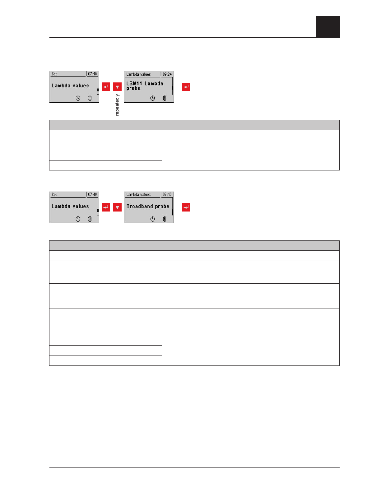
Adjustable parameters - Lambda probe - LSM11 Lambda probe
Parameter Description
Residual oxygen content 1.9% Shows the current values for the relevant Lambda probe parameter
Lambda probe voltage measured 52.00 m
Lambda probes correction value 0.0
Lambda probe voltage corrected 52.00 m
Adjustable parameters – Lambda values – Broadband probe
repeatedly
Parameter Description
Residual oxygen content 1.9% Displays the current value
Broadband probe types
(1…BOSCH / 2…NTK)
(3…LSM11 input)
1 Defines the probe type used
Broadband probe calibration
(probe must be at
21% O2)
NO After activation of the lambda probe heating, the lambda probe can be
calibrated using this value.
CAUTION: The probe must be at 21% O2 (air).
Broadband probe heating current 0.00A Display of the current values for the relevant broadband probe parameter
Broadband probe heating voltage 0.00V
Broadband probe Nernst
voltage
0.000V
Broadband probe pump current 0.000m
Broadband probe internal resistance 0R
Menu overview and parameters
5
Menu - System
Operating Instructions Lambdatronic S 3200 | B0361214_en 73
Page 74
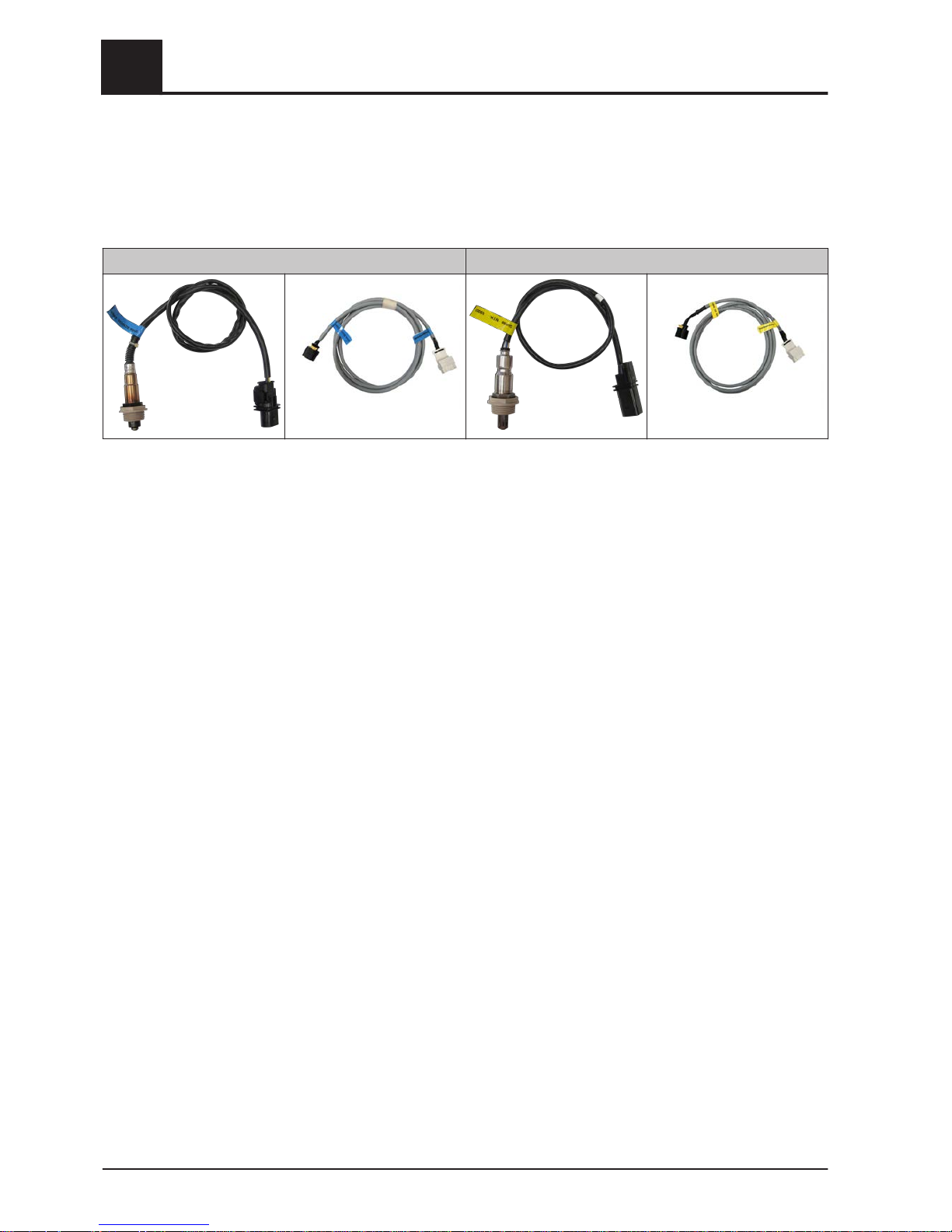
Determining the probe type
The type of probe installed must be determined before starting calibration. To this end,
coloured stickers (BOSCH = blue, NTK= yellow) are affixed to the connection cable of
the probe, as well as to each end of the extension cable.
BOSCH broadband probe NTK broadband probe
Once the type of probe has been determined, the parameters need to be adjusted ac‐
cordingly in the controller.
Starting calibration
❒ Set the type of probe used
➥ BOSCH = 1, NTK = 2
For boilers with manual loading:
❒
Open the insulated door
➥ Before starting calibration, the insulated door must be open for at least 3 - 4
minutes so that the probe is warm enough and the boiler is sufficiently ventila‐
ted
For boilers with automatic loading:
❒ Boiler must be switched off
➥ Status "Boiler OFF" or "Standby"
❒ Set "Lambda probe heating" parameter in the "Manual" - "Digital out-
puts" menu to "1"
➥ Heat Lambda probe for at least 2 minutes
Calibrate probe:
❒ Go to parameter "Broadband probe calibration"
❒ Set parameter to "YES" and press the enter key
➥ Automatic calibration of the broadband probe begins
➥ Once calibration is complete the parameter is automatically set to "NO" and the
broadband probe is ready for use
5
Menu overview and parameters
Menu - System
74 Froling GesmbH | A-4710 Grieskirchen, Industriestraße 12 | www.froeling.com
Page 75
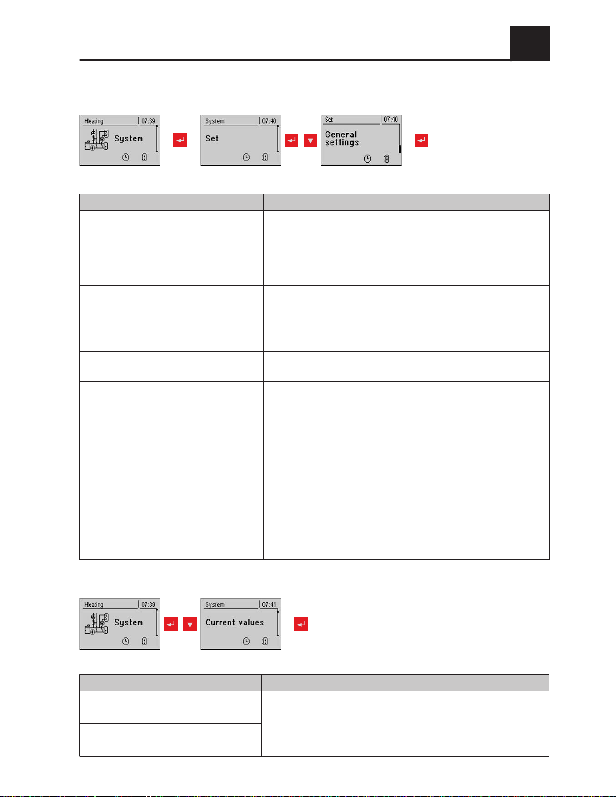
General settings
repeatedly
Parameter Description
Very dry material (w < 15%) param‐
eter adopt next line
NO If this parameter is set to "YES" and then the parameter “Adopt boiler
standard values” is set to “YES”, the parameters are automatically
adjusted for very dry firewood.
Adopt boiler standard values NO If this parameter is set to "YES", the current parameters for the selected
boiler are set. After the values have been adopted the parameter jumps to
"NO”.
Abort heating up --> ID fan off, close
air flaps
NO If this parameter is set to “YES”, the boiler heating up process can be
aborted.
NOTE: Criteria for “Off” status must be fulfilled.
Modem installed NO If the boiler has a modem for data transfer, this value must be set to
"YES".
Memory cycle of data logger 5 s Do not change this value!
This is the memory cycle used for saving data onto the data logger.
Send a line break when ASCII data
output on COM2
NO
COM 2 is used as a MODBUS inter‐
face
NO YES:
The COM 2 interface can be used for connection with a MODBUS (RTU /
ASCII)
NO:
The COM 2 interface sends the most important boiler values every sec‐
ond
MODBUS address 2 Adjustable parameters for MODBUS
MODBUS protocol
(1 – RTU / 2 – ASCII)
1
Set hours since last maintenance to0NO To reset the counter “Hours since last maintenance”, this parame‐
ter must be set to "YES”. After the has been reset, the parameter jumps to
"NO”.
5.12.2 Current values
Parameter Description
Boiler temperature 77°C Display of the current values for the relevant parameter.
:
:
Flue gas temperature 210°C
Flue gas setpoint 212°C
Boiler control variable 99%
Menu overview and parameters
5
Menu - System
Operating Instructions Lambdatronic S 3200 | B0361214_en 75
Page 76
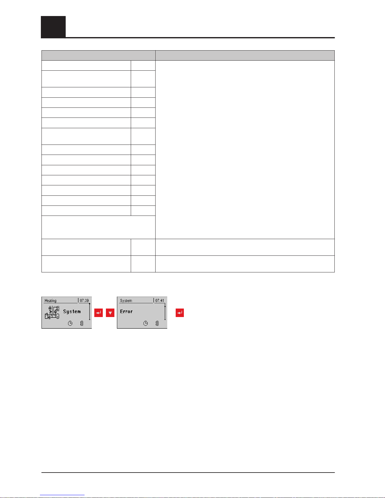
Parameter Description
ID fan control 75%
ID fan speed 2230
rpm
Primary air 20%
Position of primary air flap 19%
Secondary air 5%
Position of secondary air flap 4%
Flue gas temperature after calorific
value heat exchanger
160°C
Outside air temperature 23°C
Board temperature 33°C
Return sensor 61°C
Service hours 26 h
Service hours in slumber 1 h
Ignition service hours 0 h
Ignition starts 0
Software version
Version: 50.04
Build: 05.09
Cust. no.: 263586
Boiler no.: 560
System operator data
Service hours of boiler 2 (burner
contact)
2
5.12.3 Error list
repeatedly
⇨ See "Error display" [page 83]
5
Menu overview and parameters
Menu - System
76 Froling GesmbH | A-4710 Grieskirchen, Industriestraße 12 | www.froeling.com
Page 77
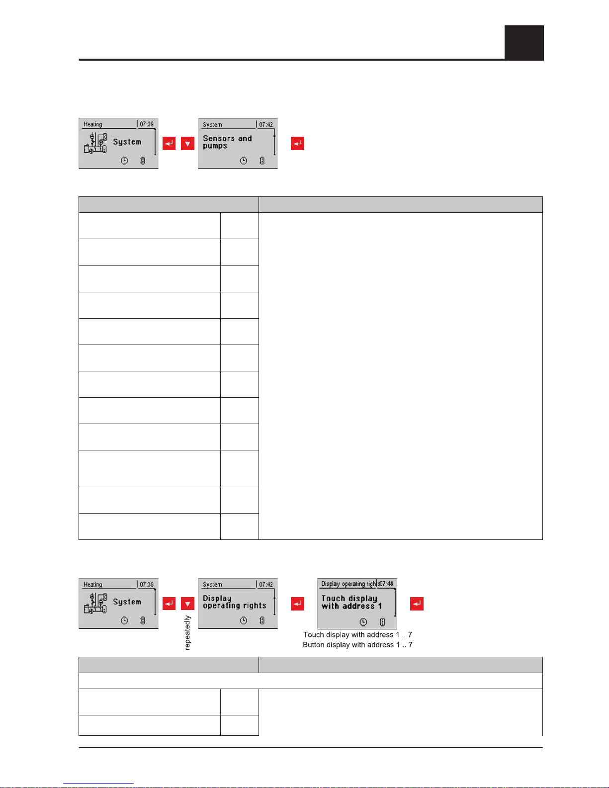
5.12.4 Parameters for sensors and pumps
repeatedly
Parameter Description
Which sensor is used for
storage tank top
0.1 Setting the bus addresses of the sensors and pumps used
⇨ See "Setting the module address" [page
20]
The display of the parameters varies depending on the system set.
Note the information on hydraulic systems in the "Lambdatronic S 3200
energy systems" documents.
Which sensor is used for
bottom storage tank
0.2
Which pump is used for the
storage tank
0.1
Which sensor is used for the
backup boiler
0.5
Which output is used for
unloading standby boiler
Pump 1
Which sensor is used for the
storage tank reference
0.2
Which pump is used for the
solar collector
1.1
Which pump is used for the
solar isolating valve
1.2
Which sensor is used for top
DHW tank 1
0.3
Which sensor is used for solar refer‐
ence
DHW tank 1
0.4
Which sensor is used for bottom
DHW tank 1
0.3
Which pump is used for
DHW tank 1
0.2
5.12.5 Display operating rights
Parameter Description
HEATING SYSTEM:
Allow access to
heating circuit 01?
YES Allocate access rights for changing heating circuit parameters to the indi‐
vidual controls (address 1 - 7)
WARNING! The parameters are set to "YES" at the factory, therefore ev‐
ery control has access to all parameters by default!
:
Menu overview and parameters
5
Menu - System
Operating Instructions Lambdatronic S 3200 | B0361214_en 77
Page 78
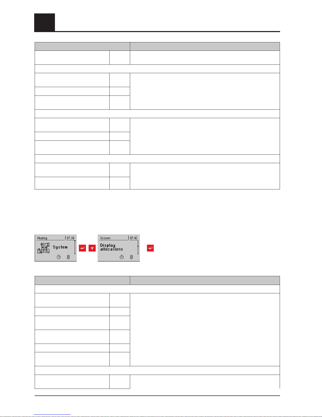
Parameter Description
Allow access to
heating circuit 18?
YES
DHW TANK SYSTEM:
Allow access to DHW
tank 01?
YES Allocate access rights for changing DHW tank parameters to the individual
controls (address 1 - 7).
WARNING! The parameters are set to "YES" at the factory, therefore ev‐
ery control has access to all parameters by default!
:
Allow access to DHW
tank 08?
YES
STORAGE TANK SYSTEM:
Allow access to
storage tank 01?
YES Allocate access rights for changing storage tank parameters to the individ‐
ual controls (address 1 - 7).
WARNING! The parameters are set to "YES" at the factory, therefore ev‐
ery control has access to all parameters by default!
:
Allow access to
storage tank 04?
YES
SOLAR SYSTEM:
Allow access to
solar 01?
YES Allocate access rights for changing solar parameters to the individual con‐
trols (address 1 - 7).
WARNING! The parameters are set to "YES" at the factory, therefore ev‐
ery control has access to all parameters by default!
NOTICE! The operating rights of the room consoles should be allocated from the boil‐
er control panel, as unrestricted access is only possible here.
5.12.6 Display allocations
repeatedly
Parameter Description
ROOM SENSOR CORRECTION:
Deviation of room sensor from touch
display with address 1
0°C If the current room temperature does not match the displayed/evaluated
value, this parameter can be used to adjust the evaluation of the room
temperature sensor.
:
Deviation of room sensor from touch
display with address 7
0°C
Deviation of room sensor from but‐
ton display with address 1
0°C
:
Deviation of room sensor from but‐
ton display with address 7
0°C
HEATING SYSTEM:
Touch display with address 1 is allo‐
cated to the following heating circuit:
None Allocates the relevant control (address 1 - 7) to a particular heating circuit.
5
Menu overview and parameters
Menu - System
78 Froling GesmbH | A-4710 Grieskirchen, Industriestraße 12 | www.froeling.com
Page 79
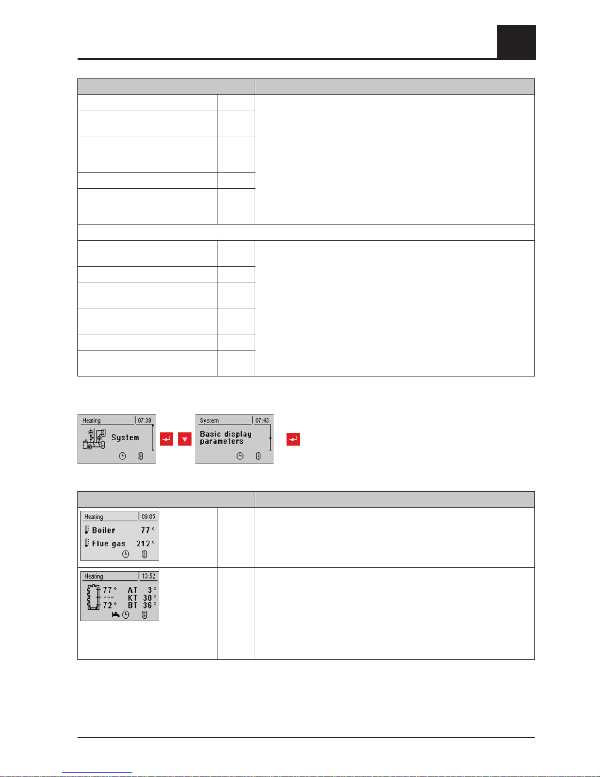
Parameter Description
:
WARNING! The parameters are set to "none" at the factory, so the heating
circuit functions (room temperature sensor, party mode, setback mode, ...)
are not possible on this control by default!
Touch display with address 7 is allo‐
cated to the following heating circuit:
None
Button display with address 1 is al‐
located to the following heating cir‐
cuit:
None
:
Button display with address 7 is al‐
located to the following heating cir‐
cuit:
None
DHW TANK SYSTEM:
Touch display with address 1 is allo‐
cated to the following DHW tank:
None Allocates the relevant control (address 1 - 7) to a particular DHW tank.
WARNING! The parameters are set to "none" at the factory, so the hot wa‐
ter functions (function key) are not possible on this control by default!
:
Touch display with address 7 is allo‐
cated to the following DHW tank:
None
Button display with address 1 is al‐
located to the following DHW tank:
None
:
Button display with address 7 is al‐
located to the following DHW tank:
None
5.12.7 Basic display parameters
repeatedly
Parameter Description
You can individually adjust how the two items are shown in the basic dis‐
play, and for each item you can choose from the following parameters:
Boiler, flue gas, external, room, DHW tank, storage tank top, storage tank
bottom, storage tank graphic, collector T., flue gas, domestic hot water, re‐
sidual O2, O2 contr., feed rate, ID fan
Instead of defining items 1 and 2 separately, you can select the storage
tank graphic.
In addition to the storage tank graphic, the storage tank top, middle (if
present) and bottom temperatures are displayed.
ET … external temperature
BT … boiler temperature
RT … room temperature (on RBG 3200 BT is replaced with RT)
DT … DHW temperature
Menu overview and parameters
5
Menu - System
Operating Instructions Lambdatronic S 3200 | B0361214_en 79
Page 80
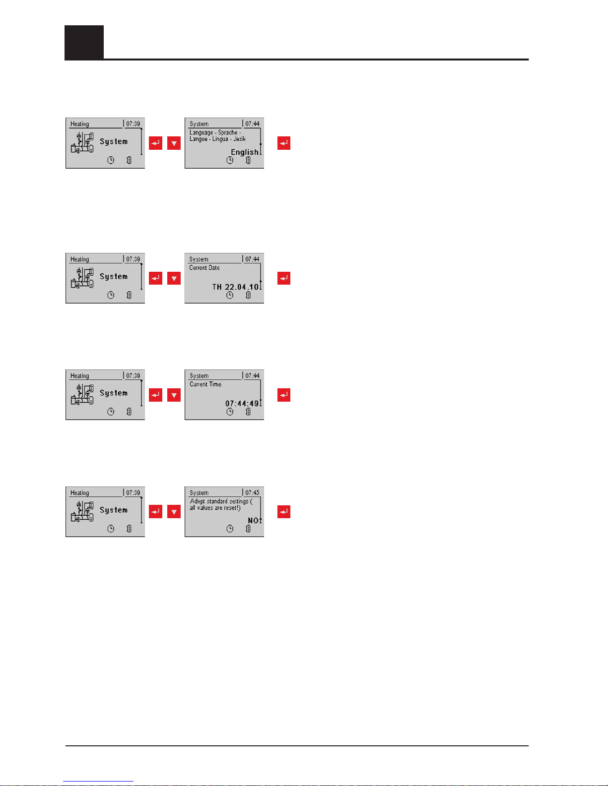
5.12.8 Changing languages
repeatedly
5.12.9 Changing the date
repeatedly
5.12.10 Changing the time
repeatedly
5.12.11 Standard settings
repeatedly
❒ Adopt standard factory settings. This resets all parameters! After resetting, the pa‐
rameters for the boiler must be reset or else boiler functioning is no longer guaran‐
teed (Only with service code).
5.12.12 Current user level
⇨ See "Changing the operating level" [page 28]
5
Menu overview and parameters
Menu - System
80 Froling GesmbH | A-4710 Grieskirchen, Industriestraße 12 | www.froeling.com
Page 81
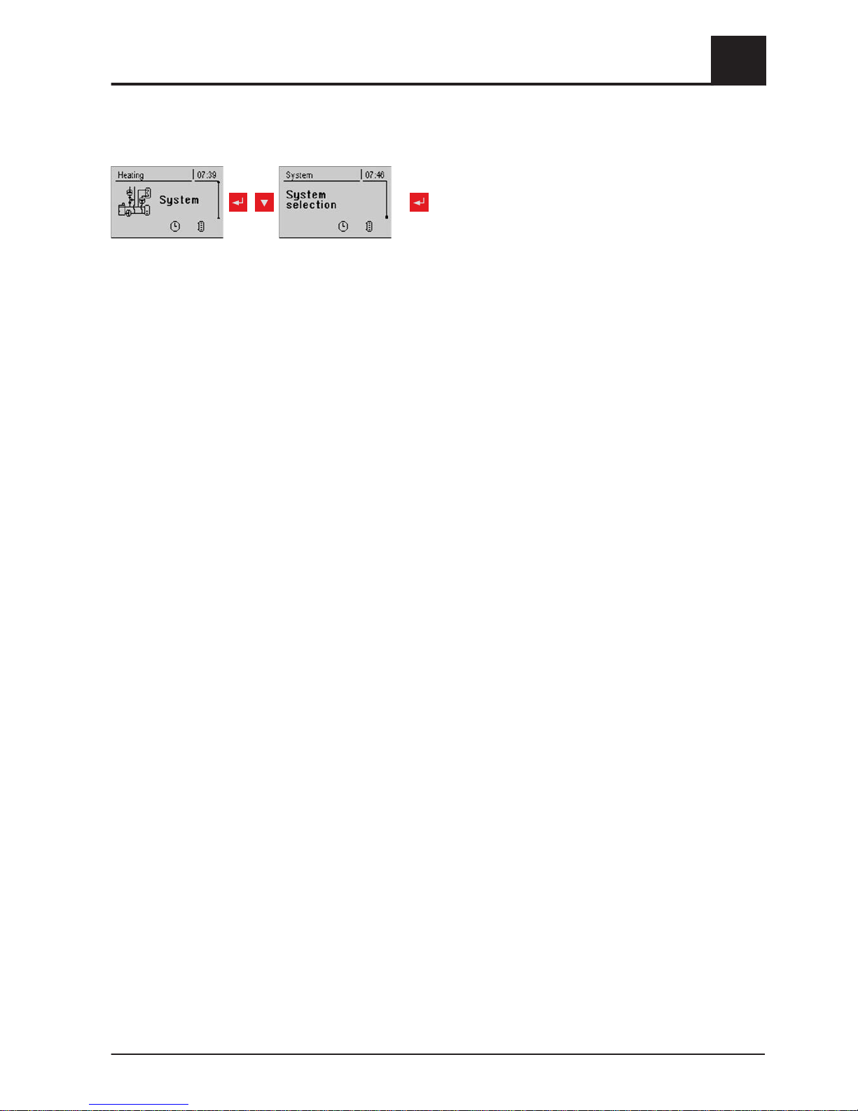
5.12.13 System type
repeatedly
⇨ See "Setting the system type" [page 29]
Menu overview and parameters
5
Menu - System
Operating Instructions Lambdatronic S 3200 | B0361214_en 81
Page 82

5.13 PWM / 0 - 10V settings
Description
▪ Normal pump (pump with load-tap changer)
Set when a standard pump a switching valve with RC element is run at the respective output. When using a switching
valve, set the minimum speed of the output to 100%. When a pump is used, it is controlled at the 230V output using
pulse packets.
▪ PDM / field pump
There is a permanent power supply of 230V at the output for the high efficiency pump. The pump is controlled using
pulse duration modulation at the respective PDM output.
▪ PDM / Solar pump
Here again, the pump is controlled by means of pulse duration modulation at the respective PDM output. In this case,
however, the characteristic line is inverted and can only be used for specially marked high efficiency solar pumps.
▪ PDM field Pump+valve
The signal for the field pump is emitted at the PDM output. If the signal exceeds 2%, the 230V output is switched on. If
the signal is below 2% for more than 4 minutes, the output is switched off again.
▪ 0 – 10V / field pump
▪ 0 – 10V / solar pump
▪ 0 – 10V field Pump+valve
The same functions that apply with PDM apply to the parameter values with 0-10V. The only difference is that instead
of pulse duration modulation, a 0-10V signal is used to control the pump.
5
Menu overview and parameters
PWM / 0 - 10V settings
82 Froling GesmbH | A-4710 Grieskirchen, Industriestraße 12 | www.froeling.com
Page 83
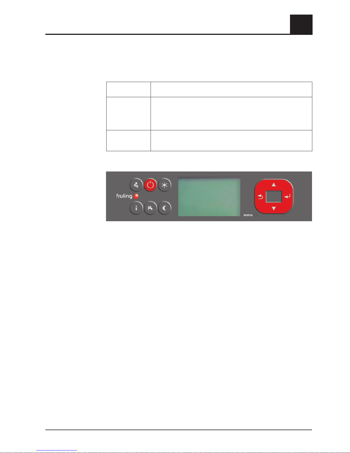
6 Troubleshooting
The term "fault" is a collective term for warnings, errors and alarms. The boiler reacts
differently to the three types of message:
WARNING In case of warnings the status LED flashes orange and the boiler initially
continues controlled operation.
ERROR In case of errors, the status LED flashes red, the boiler follows shutdown
procedure and remains in operating status "
Off ", until the error is re‐
solved.
After troubleshooting, the boiler switches back to the operating status
"Off".
ALARM An alarm triggers a system emergency stop. The status LED flashes red,
the boiler switches off immediately and the heating circuit controller and
pumps remain active.
6.1 Procedure for fault messages
When a fault occurs:
▪
The status LED flashes red or orange
▪ The display shows all the current fault messages and the warning symbol in the
status line
Troubleshooting
6
Procedure for fault messages
Operating Instructions Lambdatronic S 3200 | B0361214_en 83
Page 84
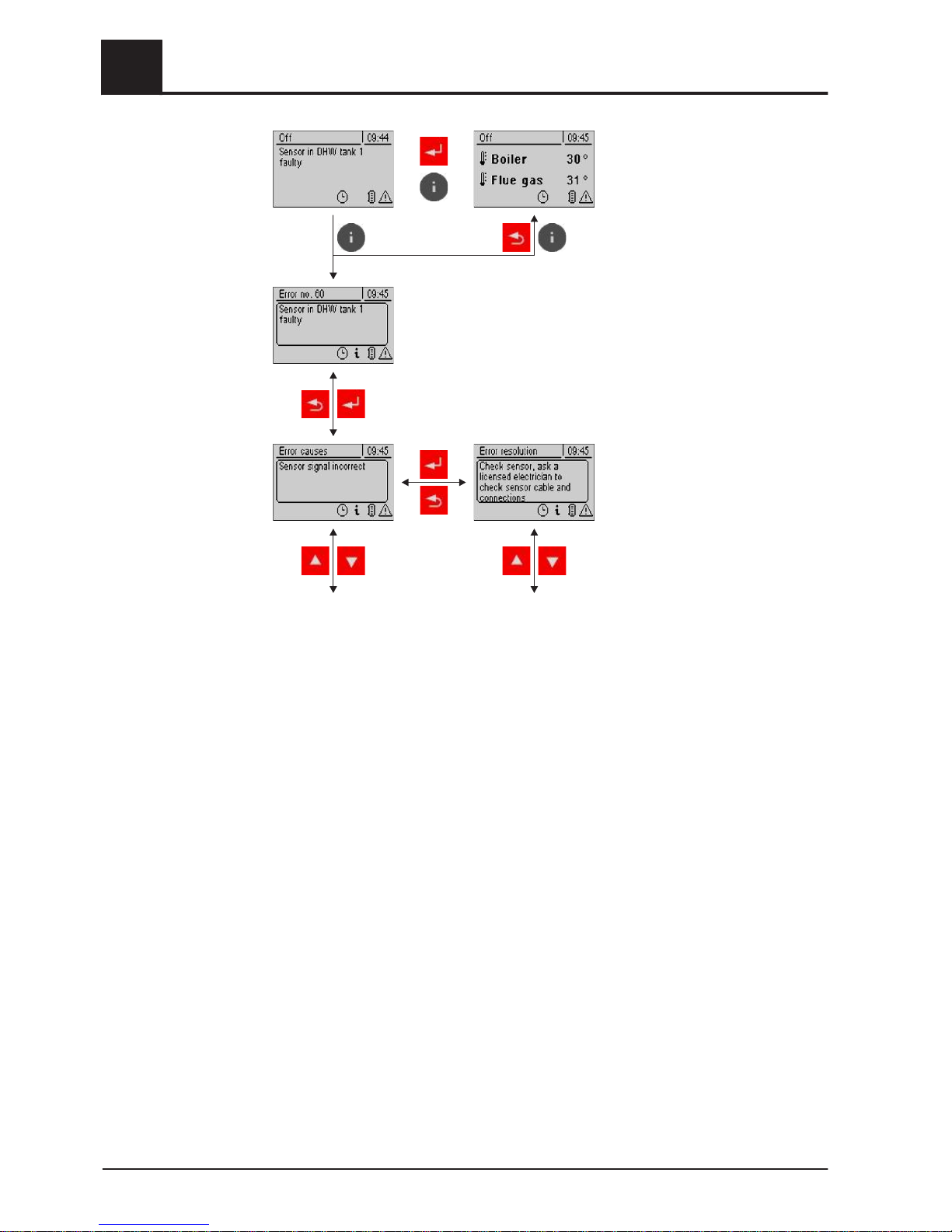
After pressing the enter key the
fault is acknowledged.
The warning symbol in the status
line shows that the fault is still
pending.
Pressing the info key displays the
fault as info text with the related
fault number.
The warning symbol only
switches off when the fault has
been resolved!
After pressing the enter key an in‐
fo text on the cause of the fault is
displayed. Pressing the enter key
again displays instructions for re‐
solving the fault.
If a fault has various causes or
the cause can be resolved in vari‐
ous ways, you can scroll through
with the navigation keys.
6
Troubleshooting
Procedure for fault messages
84 Froling GesmbH | A-4710 Grieskirchen, Industriestraße 12 | www.froeling.com
Page 85
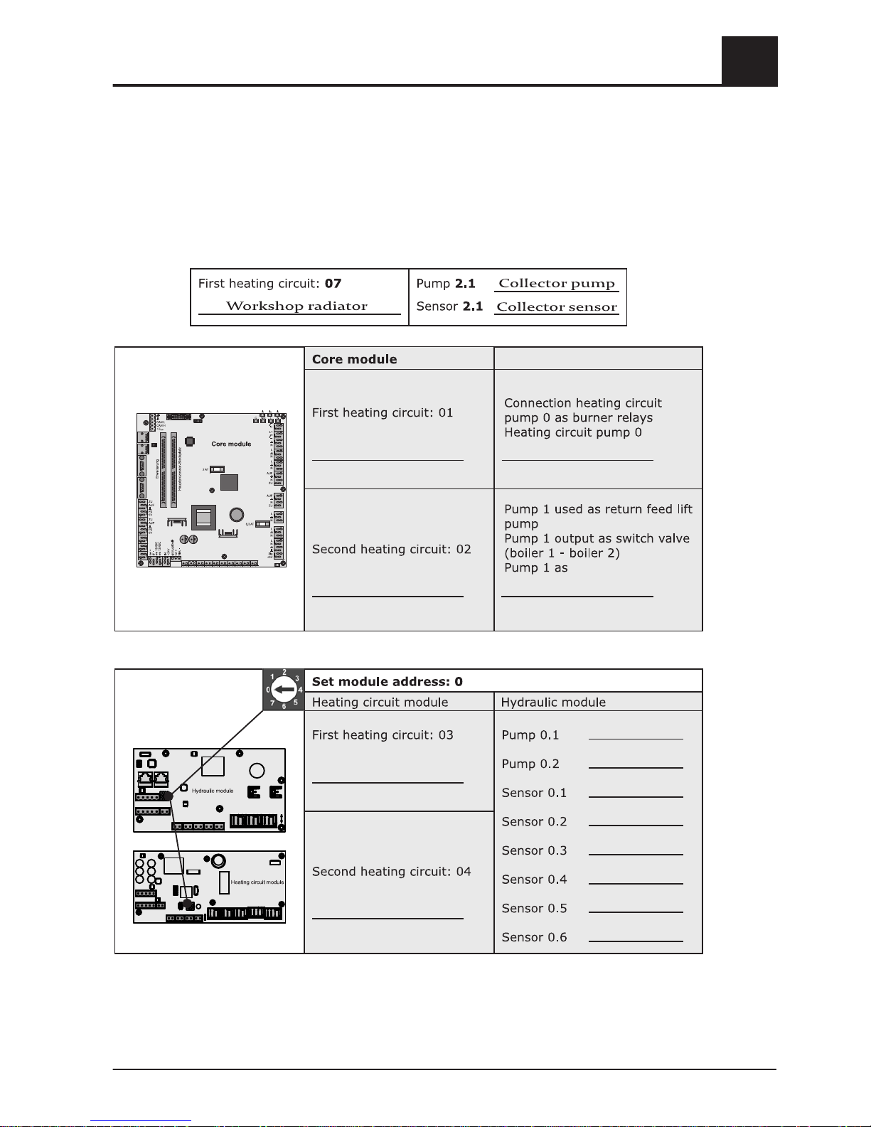
7 Setting protocol
The following tables show which heating components are allocated to the connections.
Below the heating circuit number it notes the heating area, for which this heating cir‐
cuit is used. The relevant connected unit should be noted next to the pumps or sen‐
sors.
Example: Module address = 2;
Setting protocol
7
Operating Instructions Lambdatronic S 3200 | B0361214_en 85
Page 86
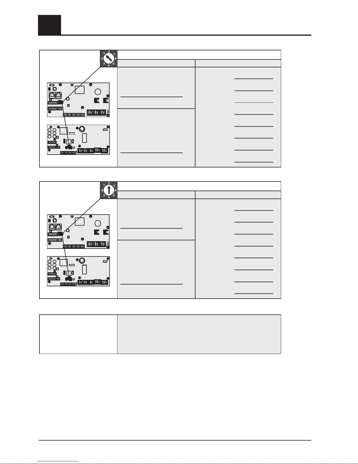
Heatingcircuitmodule
Hydraulicmodule
Heatingcircuitmodule
Hydraulicmodule
Setmoduleaddress:2
Firstheatingcircuit:07
Secondheatingcircuit:08
Heatingcircuitmodule Hydraulicmodule
Pump2.1
Pump2.2
Sensor2.1
Sensor2.2
Sensor2.3
Sensor2.4
Sensor2.5
Sensor2.6
Setmodueaddress:1
Firstheatingcircuit:05
Secondheatingcircuit:06
Heatingcircuitmodule Hydraulicmodule
Pump1.1
Pump1.2
Sensor1.1
Sensor1.2
Sensor1.3
Sensor1.4
Sensor1.5
Sensor1.6
Finalcheck
Buscablecorrectlyconnected(see
“Connectingthebuscable”))
Addressingcorrectlycarriedoutandrecorded
Jumperplacedatthelastmodule
7
Setting protocol
86 Froling GesmbH | A-4710 Grieskirchen, Industriestraße 12 | www.froeling.com
Page 87
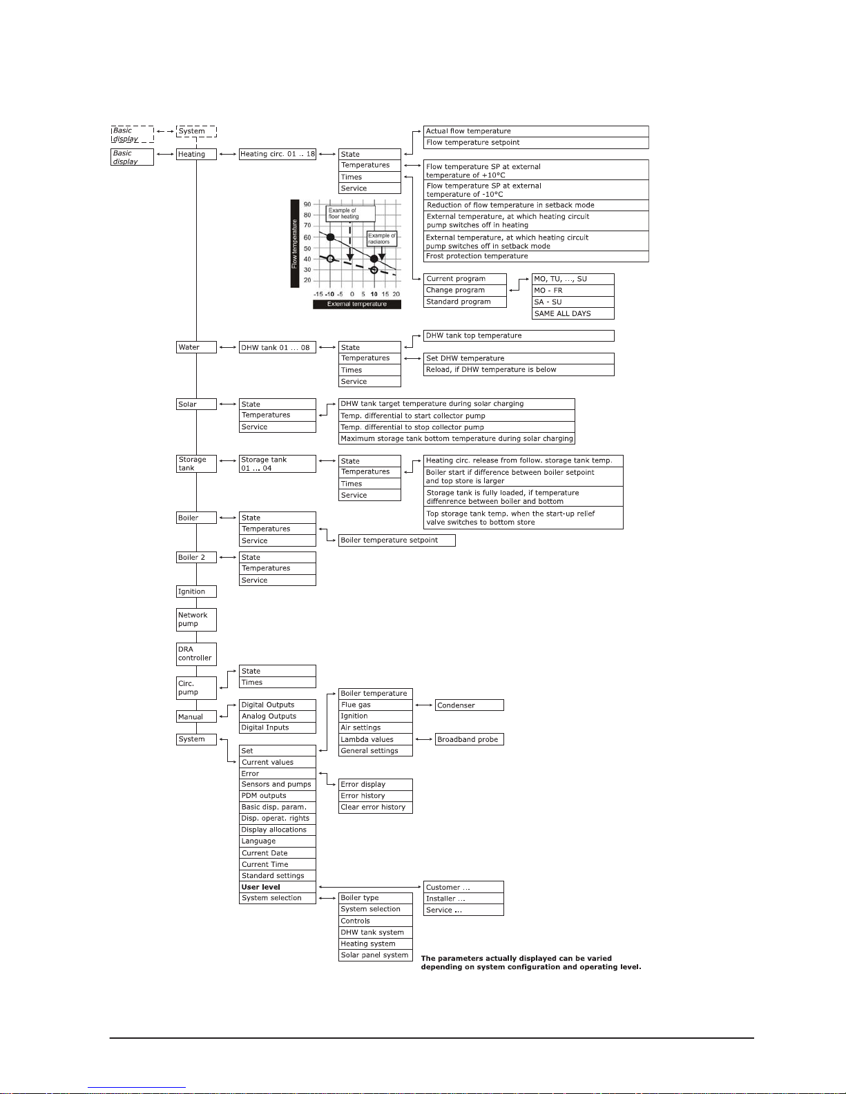
Menu structure - Lambdatronic S3200
Operating Instructions Lambdatronic S 3200 | B0361214_en 87
 Loading...