

Operating Instructions
FHG Turbo 3000
Read and follow the operating instructions and safety information.
Edition: 02/2005
Fröling Heizkessel- und Behälterbau Ges.m.b.H, Industriestraße 12, A-4710 Grieskirchen
Tel. +43 (0) 7248 606-0 Fax +43 (0) 7248 606-600 info@froeling.com www.froeling.com

Table of Contents
Page 2 a
B 003 04 05 a
I
1 Overview 4
2 Safety 6
2.1 Permitted uses 6
2.1.1 Permitted fuels ............................................................................................................... 6
2.1.2 Who May Operate the Boiler .......................................................................................... 6
2.2 Safety Information 7
2.2.1 Official approval and reporting obligations ..................................................................... 7
2.2.2 Domestic hot water requirements................................................................................... 7
2.2.3 Ventilating the Boiler Room............................................................................................ 7
2.2.4 Heating System Installation/Standards .......................................................................... 8
Return feed lift ........................................................................................................... 8
2.2.5 Chimney Connection / Chimney System........................................................................ 8
Design information..................................................................................................... 8
Draught limiter ........................................................................................................... 8
2.3 Safety devices 9
Devices for Preventing the Boiler from Over-heating ................................................ 9
2.4 Residual risks 10
2.5 Emergency actions 10
3 Operating the system 11
3.1 Initial start-up 11
3.1.1 Checking the heating system ....................................................................................... 11
3.2 Heating up the boiler 12
3.2.1 Switching on the system............................................................................................... 12
3.2.2 Switching on the boiler ................................................................................................. 12
3.2.3 Load the boiler with fuel and fire it up........................................................................... 12
3.2.4 Controlling the boiler .................................................................................................... 13
3.2.5 Refilling the fuel............................................................................................................ 13
Operating with a storage tank.................................................................................. 13
Operating without a storage tank............................................................................. 14
3.2.6 Switching off the system............................................................................................... 14
4 Boiler maintenance 15
4.1 Inspection, Cleaning and Maintenance 15
4.1.1 Daily Maintenance........................................................................................................ 15
Cleaning the heat-exchanger pipes (with heat-exchanger technology)................... 15
4.1.2 Weekly Maintenance .................................................................................................... 15
Removing the ash.................................................................................................... 15
Cleaning the passage to the side of the combustion chamber ................................ 16
Checking the thermal discharge safety device ........................................................ 16
Checking the system pressure ................................................................................ 16
4.1.3 Monthly Maintenance ................................................................................................... 17
Cleaning the grating................................................................................................. 17
Cleaning the heat-exchanger pipes (without heat-exchanger technology).............. 17

Table of Contents
Fröling Heizkessel- und Behälterbau Ges.m.b.H, Industriestraße 12, A-4710 Grieskirchen Page 3
Tel. +43 (0) 7248 606-0 Fax +43 (0) 7248 606-600 info@froeling.com www.froeling.com Edition: 23.03.2005
I
Cleaning the flue gas sensing elements...................................................................17
4.1.4 Annual Maintenance .....................................................................................................18
Checking the primary air openings...........................................................................18
Cleaning the carbonization gas duct ........................................................................18
Cleaning the induced draught ventilator...................................................................18
Checking the soundness of door seals.....................................................................19
Cleaning the flue gas pipe........................................................................................19
Checking the draught controller flap and explosion flap...........................................19
4.2 Service Agreement 19
4.3 Instructions for Measuring Emissions 20
5 Troubleshooting 21
5.1 External faults 21
5.2 Internal boiler faults 21
5.2.1 Resetting the safety temperature limiter (STB) .............................................................21
5.2.2 Acknowledging a fault message....................................................................................21
6 Appendix 22
6.1 Addresses 22
6.1.1 Manufacturer’s Address ................................................................................................22
6.1.2 Your Installer’s Address ................................................................................................22
6.2 Conformity Certificate 23
6.3 Pressure equipment regulation 24
6.4 Space for Notes 25
Overview
Page 4 a
B 003 04 05 a
1
Dear Customer,
Congratulations on choosing a quality product from FRÖLING.
The FRÖLING FHG Turbo 3000 is a state-of-the-art design that conforms to all currently
applicable standards and testing guidelines.
Please read and observe the operating instructions and always keep them available in close
proximity to the boiler. They contain safety information and all the operation and maintenance
specifications needed to operate the boiler safely, properly, and economically.
1 Overview
7.9
1
2
7
6
3
4
5
8.1
8.2
8.7
8.6 8.4
8
7.10
9
7.1
7.2
7.3
7.4
7.5
7.6 7.8
7.7
8.5
8.3
10
11

Overview
Fröling Heizkessel- und Behälterbau Ges.m.b.H, Industriestraße 12, A-4710 Grieskirchen Page 5
Tel. +43 (0) 7248 606-0 Fax +43 (0) 7248 606-600 info@froeling.com www.froeling.com Edition: 23.03.2005
1
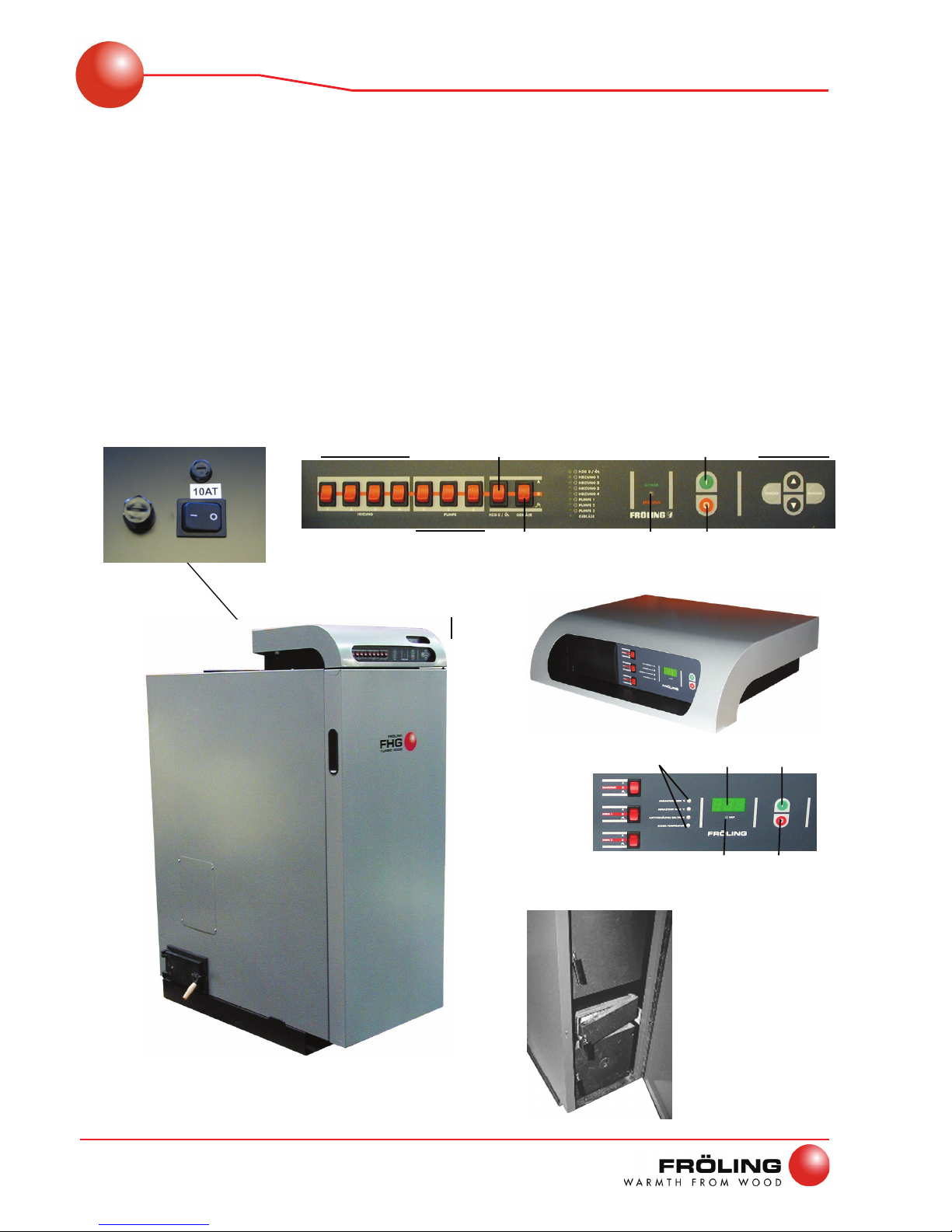
Pos. Component
1
FHG Turbo 3000 Firewood Boiler
2
Insulating door for reduced heat radiation
3
Fuel loading door
4
Pre-heating chamber door
5
Combustion chamber door
6
Side cleaning port door
7
Lambdatronic S3100 Control System
7.1
HEATING 1-4 (Auto/Off/Manual)
7.2
PUMP 1-3 (Auto/Off/Manual)
7.3
HTG 0 / OIL (Auto/Off/Manual)
7.4
BLOWER FAN (Auto/Off/Manual)
7.5
The respective LED illuminates when Pos. 7.1 – 7.4 are active
7.6
Status LED (Operating Status): - long, green blinking light: Boiler activated
- short, green blinking light: Boiler deactivated
- red blinking light: Malfunction
7.7
START key: Switch on boiler
7.8
STOP key: Switch off boiler (not possible during heating operation)
7.9
MENU keys: Manipulate the program menus
7.10
Two-line display for indicating the operating statuses
8
Digitronic S3100 Control System
8.1
INDUCED DRAUGHT UNIT (Automatic/Off/Manual)
8.2
CIRCUIT 1-2 (Automatic/Off/Manual)
8.3
Controller for adjusting: flue gas temperatures, air status, boiler temperature
8.4
3-digit display for indicating: boiler temperature, flue gas temperature, Pos. 8.3 controller
settings
8.5
Heating circuit pump (HKP) status LED: illuminates on reaching the release temperature for the
heating circuit pump
8.6
START key: Switch on boiler
8.7
STOP key: Switch off boiler (not possible during heating operation)
9
Main switch: switches the system on and off
10
STB – Safety Temperature Limiter
11
Power network fusing of the controller (glass-tube fusing 20 x 5mm 10AT)
Safety
Permitted Uses
Page 6 a
B 003 04 05 a
2
2 Safety
2.1 Permitted uses
The boiler should only be operated when it is fully efficient. The boiler should be operated in
accordance with the instructions given in this manual. Implement all the necessary safety
precautions. Before you start using the boiler, make sure that you are aware of the potential
hazards involved. Ensure that any malfunctions, which might impact safety are traced and
removed immediately.
The FHG Turbo 3000 series of heating boilers is intended exclusively for heating
domestic hot water. Only use the fuels specified below 2.1.1.
The manufacturer or supplier are not liable for any damages resulting from nonpermitted uses.
2.1.1 Permitted fuels
For Austria:
Firewood with a max. length of 55cm (w < 25%)
Waste-wood as per ÖNORM M 7133 – G100 (w < 25%)
Saw-mill waste, dry (w < 25%)
Values in practice: Hardwood 2 years in dry storage
Soft wood 1 year in dry storage
Coarse waste-wood 1 year in dry storage
For Germany:
Fuel class 4 (1. BimSchV i. d. g. F.)
IMPORTANT
Caustic sediment layers or condensation in the boiler as the result of burning unauthorized
fuels!
This will void your guarantee. Damage or corrosion in the combustion
chamber and boiler may result!
2.1.2 Who May Operate the Boiler
Only trained operators are permitted to operate the boiler.
IMPORTANT
No unauthorized access to the boiler room.
Possible personal injury and damage to property!
It is the responsibility of the operator to ensure that unauthorized persons, especially
children, are kept away from the boiler.

Safety
Safety Information
Fröling Heizkessel- und Behälterbau Ges.m.b.H, Industriestraße 12, A-4710 Grieskirchen Page 7
Tel. +43 (0) 7248 606-0 Fax +43 (0) 7248 606-600 info@froeling.com www.froeling.com Edition: 23.03.2005
2
2.2 Safety Information
As a rule, the operator is not authorized to modify or disable the safety equipment.
In addition to the operating instructions and the applicable regulations for the country in which
the boiler will be operated, all fire, police, and electrical regulations must be observed.
2.2.1 Official approval and reporting obligations
NOTE
Each heating system must be officially approved.
In Austria:
- Report to the construction authorities of the community or magistrate
In Germany:
- Report to the chimney sweep or the construction authorities
2.2.2 Domestic hot water requirements
If the system is topped up or refilled:
U Prepare (soften) the water in order to counteract boiler scaling.
Applicable standards:
Austria: ÖNORM H 5195
Germany: VDI 2035
2.2.3 Ventilating the Boiler Room
The supply and exhaust air openings should be arranged as nearly opposite each other as
possible to achieve a good thermal draught effect.
Draw in the supply air directly from outside. Expel the exhaust air directly to the outside.
Applicable standards:
- TRVB H 118
- ÖNORM H 5170
Unless otherwise directed by local regulations:
Provide an exhaust air cross-section of 2 cm
2
per kW of boiler rated output, however, a
total cross-section of at least 200 cm
2

Safety
Safety Information
Page 8 a
B 003 04 05 a
2
2.2.4 Heating System Installation/Standards
ÖNORM/DIN EN 12828 governs the installation of the heating system:
Return feed lift
If the heated water return feed is under the minimum return temperature, a portion of the heated
water outfeed will be mixed in.
IMPORTANT
Operating without return feed lift!
Damage may result from dropping below the dew point or the formation of
condensation!
In combination with combustion residues, the condensation forms a caustic condensate which
shortens the service life of the boiler!
Take the following precautions:
A return feed lift is a regulatory requirement!
2.2.5 Chimney Connection / Chimney System
As per EN 303-5, the entire flue gas system is to be designed in such a way as to prevent
possible seepage damage, insufficient feed pressure, and condensation.
In relation to this, it’s necessary to point out that flue gas temperatures of less than 160 K above
room temperature can occur within the permitted operating range of the boiler.
The flue gas temperatures in the cleaned state as well as additional flue gas values can be
found in the table “Boiler Data for Configuring the Chimney” in the assembly instructions.
Design information
Make a connection using the shortest path rising between 30 – 45° to the chimney and insulate
the connecting piece.
The entire flue gas system, the chimney and its connection, must be laid out as per
ÖNORM/DIN EN13384-1.
In addition, local and other lawful regulations apply!
The chimney must be approved by a smoke trap sweeper or chimney sweep!
As per TRVB H 118, an explosion flap must be installed in the flue gas pipe or in the
chimney!
Draught limiter
Recommended: Installing a draught limiter A
Attaching the draught limiter:
U Directly under the mouth of the flue gas line, since an under-
pressure condition can always be found there!
A

Safety
Safety Devices
Fröling Heizkessel- und Behälterbau Ges.m.b.H, Industriestraße 12, A-4710 Grieskirchen Page 9
Tel. +43 (0) 7248 606-0 Fax +43 (0) 7248 606-600 info@froeling.com www.froeling.com Edition: 23.03.2005
2
2.3 Safety devices
9
Main switch For shutting down the entire system
´ All components are switched off and powered down
10
Safety Temperature Limiter
À Devices for Preventing the Boiler from Over-heating.
11
Fusing Properly fuse the control system and any electronic
components
When changing fuses, ensure the fuses are rated for
the rated current (10AT).
Devices for Preventing the Boiler from Over-heating
1. Thermal Discharge Safety Device
When 100 °C is reached, this device opens a valve and sends
cold water to the safety heat-exchanger in order to decrease
the temperature.
2. Safety Temperature Limiter
Switches off the blower fan at the maximum boiler temperature
of 105 °C. The pumps continue to run.
Once the temperature has fallen to under approx. 95 °C,
the safety temperature limiter 10 can be unlocked
mechanically.
3. Safety valve
Protection against over-heating:
When the boiler pressure reaches approximately 3 bar, the
safety valve opens and the heated water is blown off in the
form of hot water or steam.
10
9
10
11

Safety
Residual Risks/Emergency Actions
Page 10 a
B 003 04 05 a
2
2.4 Residual risks
IMPORTANT
Do not touch hot surfaces and flue gas pipes.
Burns hazard
U Only operate the boiler using the handles provided for this purpose.
U Insulate the flue gas pipes or simply avoid touching them during operation.
IMPORTANT
Opening the combustion chamber door (5) during operation.
Property damage may result and smoke and gas may accumulate!
The chimney draught is interrupted when the combustion chamber door (5) is opened during
operation
´ Flue gas escapes into the boiler room!
Thermal stressing when the combustion chamber door is opened
U Do not open the doors behind the insulating door under any circumstances while the system
is operating
IMPORTANT
Do not use unauthorized fuel types.
Equipment damage hazard.
U Only use permitted fuels.
À See 2.1.1 Permitted fuels
2.5 Emergency actions
If the system over-heats and the safety devices fail to operate, proceed as follows:
U Keep all the doors on the boiler closed.
Do not switch off the main switch under any circumstances!
U Open all mixer taps. Switch on all pumps.
Fröling’s heating circuit control takes over this function!
U Exit the boiler room and close the door
U Open any available radiator thermostat valves
If the temperature does not drop, inform the installer or Fröling’s customer service office.
À See 6.1.1 Manufacturer’s Address

Operating the System
Initial start-up
Fröling Heizkessel- und Behälterbau Ges.m.b.H, Industriestraße 12, A-4710 Grieskirchen Page 11
Tel. +43 (0) 7248 606-0 Fax +43 (0) 7248 606-600 info@froeling.com www.froeling.com Edition: 23.03.2005
3
3 Operating the system
3.1 Initial start-up
NOTE
Conduct the initial start-up with an authorized installer or Fröling’s customer
service department!
NOTE
Escaping condensation during the initial heat-up phase does not indicate a
malfunction.
´ Clean up later using a cleaning rag
IMPORTANT
Heating up the boiler too rapidly during initial start-up.
Equipment damage hazard.
If the output during the heating-up process is too great, the combustion chamber may become
damaged due to drying too rapidly!
Drying fissures, on the other hand, are normal and do not indicate a malfunction!
U Load the boiler with a small amount of waste-wood (max. 10-20% of the fuel loading
chamber)
U Ignite it and allow it to burn up with the central pre-heating chamber door open
U Repeat the procedure several times until the combustion chamber is dried out
3.1.1 Checking the heating system
Observe local regulations, but at the very least:
U Check that there is sufficient water in the heating system.
À See page 16, Checking the system pressure
U Check to see whether the heating system has been completely vented.
U Check that all the safety devices are correctly fitted and are fully efficient.
À See 2.3 Safety devices
U Check that there is sufficient ventilation and venting.
À See 2.2.3 Ventilating the Boiler Room
Operating the System
Heating up the boiler
Page 12 a
B 003 04 05 a
3
3.2 Heating up the boiler
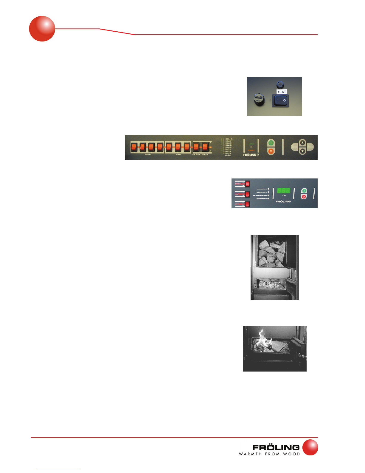
3.2.1 Switching on the system
U Switch on the main switch 9 at the control system
´ After the system check, the control system is ready
for operation
3.2.2 Switching on the boiler
Lambdatronic S3100
U Set the INDUCED DRAUGHT FAN selector switch 7.4 or
8.1 to “OFF”
U Press the START key 7.7 or 8.6
Digitronic S3100
3.2.3 Load the boiler with fuel and fire it up
U Open the insulating door and the fuel loading door
U Fill the fuel loading chamber in accordance with the
output
Use firewood with a length of approximately 50 cm and
arrange it lengthwise
The flame slot must not be obscured!
U Close the fuel loading door
U It is recommended that you do not remove the ash on the
combustion chamber during each heating-up process, to
protect the combustion chamber.
À See page 15, Removing the ash
U Open the central pre-heating chamber door
U Place some cardboard and crumpled paper under the
wood
9
8.1
8.6
7.7
7.4

Operating the System
Heating up the boiler
Fröling Heizkessel- und Behälterbau Ges.m.b.H, Industriestraße 12, A-4710 Grieskirchen Page 13
Tel. +43 (0) 7248 606-0 Fax +43 (0) 7248 606-600 info@froeling.com www.froeling.com Edition: 23.03.2005
3
Lambdatronic S3100
U Set the INDUCED DRAUGHT FAN selector switch 7.4 or
8.1 to “Automatic”
Digitronic S3100
U Leave the pre-heating chamber door open for
approximately 5 minutes
´ A bed of embers forms
U Close the pre-heating chamber door and the insulating
door
The flue gas temperature must be > 130°C!
3.2.4 Controlling the boiler
Necessary control steps. Displaying or modifying parameters:
À See the operating instructions for the “Digitronic S 3100” or “Lambdatronic S 3100”
3.2.5 Refilling the fuel
U Open the central pre-heating chamber door and check
the fuel
If the fuel in the boiler has burned up:
U Open the upper fuel loading door and refill the chamber
with fuel
Operating with a storage tank
The reloading intervals should depend exclusively on the storage tank!
If the temperature of the storage tank above has dropped to a certain temperature (floor
heating: ca. 30-40 °C, radiator heating: ca. 50 °C), reload fuel.
The amount of fuel should be measured so as to ensure that the storage tank is continuously
warmed to the maximum storage temperature (max. 80-90 °C).
The amount to reload also depends on the type of fuel!
8.1
7.4

Operating the System
Heating up the boiler
Page 14 a
B 003 04 05 a
3
Operating without a storage tank
Feed based on output
Only replenish the fuel if energy is needed!
If too much fuel is loaded:
´ The boiler drops below its minimum output limit and switches over to so-called low-
temperature operation (fan switches off)
During low-temperature operation, the efficiency drops, the emissions increase and the
boiler tars up (pitch formation!)
3.2.6 Switching off the system
IMPORTANT! Only switch off when the boiler has
cooled down.
Switch off the main switch 9 at the control system
´ The controller is switched off.
´ All the system components are powered down.
9

Boiler Maintenance
Cleaning and Maintenance
Fröling Heizkessel- und Behälterbau Ges.m.b.H, Industriestraße 12, A-4710 Grieskirchen Page 15
Tel. +43 (0) 7248 606-0 Fax +43 (0) 7248 606-600 info@froeling.com www.froeling.com Edition: 23.03.2005
4
4 Boiler maintenance
IMPORTANT
Maintenance when the boiler is hot.
Burn hazard from hot parts or in extreme cases, poisonous smoke
inhalation due to smouldering wood!
Before starting maintenance on the boiler:
U Allow the fuel to burn completely
U Allow boiler to cool off and shut down
IMPORTANT
Working on electrical components.
Hazard - Risk of electric shock
U Work on electrical components must only be carried out by authorised skilled electricians.
4.1 Inspection, Cleaning and Maintenance
Recommended: When cleaning, use an ash vacuum.
4.1.1 Daily Maintenance
Cleaning the heat-exchanger pipes (with heat-exchanger technology)
U Activate the lever of the cleaning system several times
before the heating-up process (5-10 times up and down)
4.1.2 Weekly Maintenance
Removing the ash
U Open the insulating door and the central pre-heating
chamber door
U Using the ash scraper, scrape the ash located above the
combustion chamber into the combustion chamber
U Open the combustion chamber door
U Remove the ash using the rounded ash shovel
U Shovel the ash into the container intended to receive it
Fire-proof container with a cover!
Boiler Maintenance
Cleaning and Maintenance
Page 16 a
B 003 04 05 a
4
Cleaning the passage to the side of the combustion chamber
U Open the insulating door and combustion chamber door
U Check the passage to the left and right of the combustion
chamber for ash deposits
The amount of ash will depend on the type of fuel
used!
U Clean the passages with a small brush and remove any
fallen ash
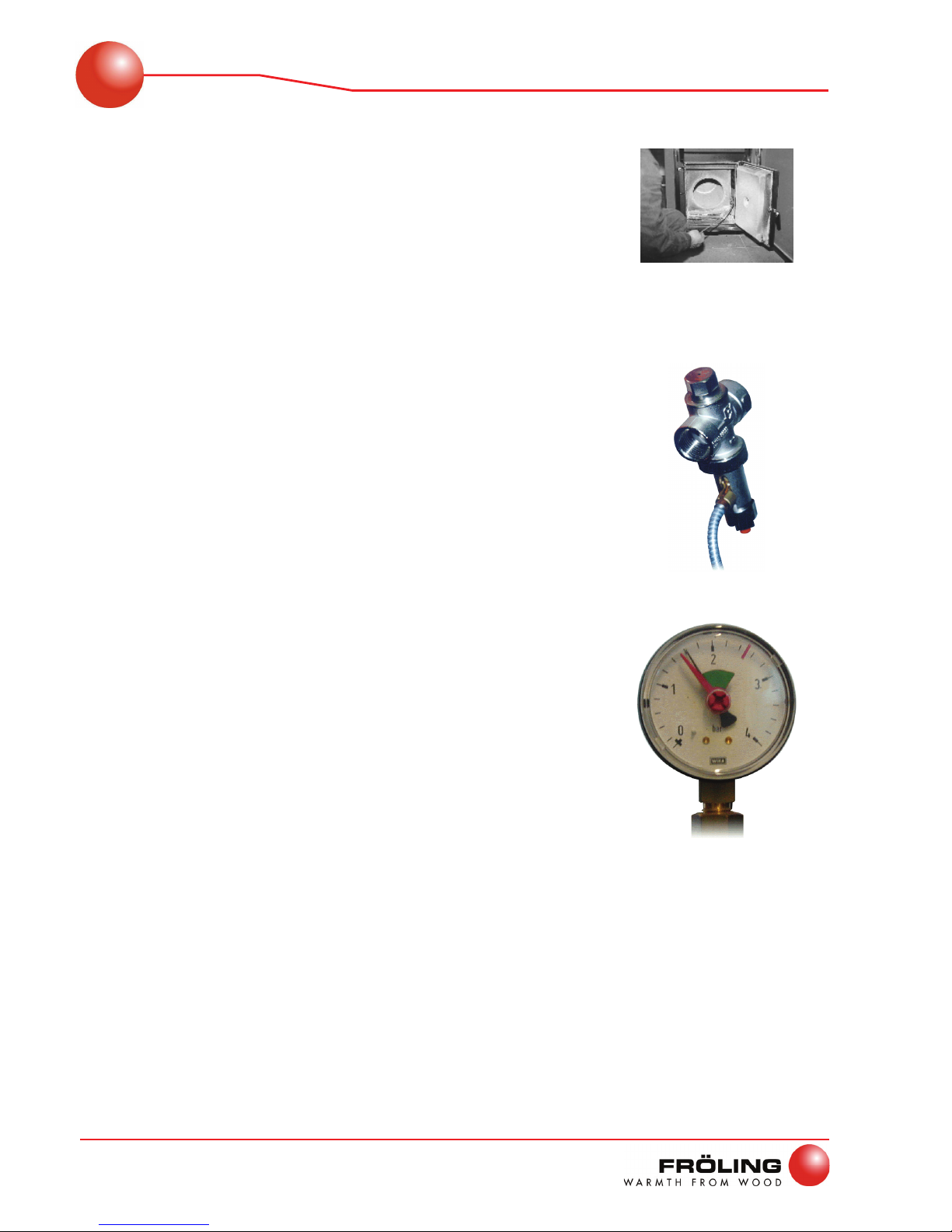
Checking the thermal discharge safety device
U Check the seal of the discharge valve
´ The discharge pipe must not drip
Exception: Boiler temperature > approx. 100 °C
If water is dripping from the discharge pipe:
U Clean the discharge safety device or have the installer
replace it if necessary
Checking the system pressure
U Read off the system pressure on the pressure gauge
´ The value must be over the pre-stressed pressure of
the expansion tank by 20%
À See the expansion tank’s operating instructions
If the system pressure is less:
U Top up the water
If this occurs frequently, the heating system does not
have a good seal!
Inform your installer!
If large pressure fluctuations are observed:
U Have the expansion tank checked

Boiler Maintenance
Cleaning and Maintenance
Fröling Heizkessel- und Behälterbau Ges.m.b.H, Industriestraße 12, A-4710 Grieskirchen Page 17
Tel. +43 (0) 7248 606-0 Fax +43 (0) 7248 606-600 info@froeling.com www.froeling.com Edition: 23.03.2005
4
4.1.3 Monthly Maintenance
Cleaning the grating
U Open the insulating door and fuel loading chamber door
U Remove the grating B
U Remove the ash deposits under the grating to ensure
trouble-free intake of secondary air!
Cleaning the heat-exchanger pipes (without heat-exchanger technology)
U Remove the upper insulating cover and the cleaning
access cover
U Using the cleaning brush, remove the ash build-up in the
pipes
The cleaning brush must be pushed all the way
through before pulling it up!
The bristles cannot be turned in the pipe!
U Open the side cleaning access door and remove the ash
Cleaning the flue gas sensing elements
U Release the retaining screw and remove the sensing element from the flue gas pipe
U Wipe off the sensing element with a clean cloth
U Slide in the flue gas sensing element to the middle of the flue gas pipe and secure it gently
with a retaining screw
B

Boiler Maintenance
Cleaning and Maintenance
Page 18 a
B 003 04 05 a
4
4.1.4 Annual Maintenance
Checking the primary air openings
U Open the insulating door and fuel loading chamber door
U Unhinge the cladding plates
U Check the primary air openings C for unobstructed air-
flow
U If necessary, clean the openings
Cleaning the carbonization gas duct
U Open the insulating door and fuel loading chamber door
U Clean the carbonization gas duct with a small brush
Carbonization gases are sucked out when the
insulating door is opened!
Cleaning the induced draught ventilator
U Detach the induced draught ventilator on the back side of
the boiler
U Check for dirt and damage
U Clean the blower wheel inside and out using a soft brush
or paint brush
Don’t move the balancing weights on the blower
wheel!
U Remove dirt and deposits from the induced draught
housing using a trowel
U Remove any fallen ash using the ash vacuum
C

Boiler Maintenance
Cleaning and Maintenance
Fröling Heizkessel- und Behälterbau Ges.m.b.H, Industriestraße 12, A-4710 Grieskirchen Page 19
Tel. +43 (0) 7248 606-0 Fax +43 (0) 7248 606-600 info@froeling.com www.froeling.com Edition: 23.03.2005
4
Checking the soundness of door seals
U Close the respective door and check its seal
U Check seal D for perfect alignment on the door frame
´ Imprint in the seal
If the seal is coloured black at several points or the imprint is
interrupted:
´ The seal is no longer efficient.
´ Tighten the door latches or replace the seal
Cleaning the flue gas pipe
U Clean the connecting pipe between the boiler and the chimney with a chimney sweep’s
brush
Very important for flat flue gas pipes!
Checking the draught controller flap and explosion flap
U Check the draught controller flap and explosion flap for ease of operation
Maximum allowable setting: 30 Pa
Ideal setting: 20 Pa
4.2 Service Agreement
Guarantee a long service-life with a service agreement!
Regular maintenance and servicing by a heating specialist will ensure a long, trouble-free
service life for your heating system. Regular servicing will ensure that your system stays
environment-friendly and operates efficiently and cost-effectively.
For this reason, FRÖLING offers a service agreement that guarantees trouble-free functioning
of the boiler and the safety systems. Please see the details in the accompanying guarantee
pass. Your Fröling customer service office is also glad to provide consultation.
D

Boiler Maintenance
Cleaning and Maintenance
Page 20 a
B 003 04 05 a
4
4.3 Instructions for Measuring Emissions
U Clean the system 2 – 5 days before the measurement
U Use fuel that the system is set up for
U Do not make any changes to the system before the measurement (up to approx. 10 minutes
prior) (Open the doors, ..)
U During the measurement, the boiler must be at least half full and a bed of embers must be
present
U The boiler temperature must be > 60 °C, the flue gas temperature must be > 160 °C
U CO
2
values should be between 10 – 14%
U Conduct a partial load measurement (for systems without a storage tank lt. BimSchV.
obligation)
U Partial load operation is evident from the flue gas temperature
´ Conduct a partial load measurement at the beginning or at the end of the emissions
measurement!
U Throttle the heat emission during the measurement
Under no circumstances should you shut down the fan or reduce its speed!
Typical values
Boiler variants without heat-exchanger technology with heat-exchanger technology
Operating phase Rated load Partial load Rated load Partial load
Flue gas temperature [°C] 190 – 220 150 – 180 160 – 190 130 – 160
CO2 – value [%] 12 – 14 10 – 14 12 – 14 10 – 14
CO [mg/Nm³]
relative to 13% O
2
100 – 1000 100 – 1000 100 – 1000 100 – 1000
Dust [mg/Nm³]
relative to 13% O
2
50 50 50 50

Troubleshooting
Fault messages
Fröling Heizkessel- und Behälterbau Ges.m.b.H, Industriestraße 12, A-4710 Grieskirchen Page 21
Tel. +43 (0) 7248 606-0 Fax +43 (0) 7248 606-600 info@froeling.com www.froeling.com Edition: 23.03.2005
5
5 Troubleshooting
There are two main types of fault: internal and external.
5.1 External faults
U The heating EMERGENCY STOP switch has been pressed.
U A house fuse (FI-protective circuit breaker) or a fuse in the control system has tripped
U The safety temperature limiter has triggered.
5.2 Internal boiler faults
When a fault has occurred and
has not yet been cleared:
- Status LED 7.6 or 8.5 blinks red
- A fault message is displayed on the
display
Internally, a distinction is made between a fault and a warning. A fault has the same effect as an
“EMERGENCY STOP” and shuts down the system immediately. A warning, on the other hand,
shuts down the system in a controlled manner.
Fault message list:
À See the operating instructions for the “Digitronic S 3100” or “Lambdatronic S 3100”
5.2.1 Resetting the safety temperature limiter (STB)
The safety temperature limiter shuts down the
boiler when it reaches a maximum temperature
of 105°C.
After the boiler has cooled down, the safety
temperature limiter 10 must be manually
unlocked:
U Unscrew the cap on the safety temperature
limiter
U Release the safety temperature limiter by
pressing with a thin rod.
5.2.2 Acknowledging a fault message
Trace and remove the fault and then:
U Press enter key 7.9
U Press start key 7.7
7.6
8.5
10
7.7
7.9

Appendix
Addresses
Page 22 a
B 003 04 05 a
6
6 Appendix
6.1 Addresses
6.1.1 Manufacturer’s Address
FRÖLING
Heizkessel- und Behälterbau GesmbH
Industriestraße 12
A-4710 Grieskirchen
Österreich
TEL 0043 (0)7248 606 0
FAX 0043 (0)7248 606 600
E-MAIL info@froeling.com
INTERNET www.froeling.com
6.1.2 Your Installer’s Address
Stamp

Appendix
Declaration of Conformity
Fröling Heizkessel- und Behälterbau Ges.m.b.H, Industriestraße 12, A-4710 Grieskirchen Page 23
Tel. +43 (0) 7248 606-0 Fax +43 (0) 7248 606-600 info@froeling.com www.froeling.com Edition: 23.03.2005
6
6.2 Conformity Certificate
EC - DECLARATION OF CONFORMITY
Product: Special wood boiler
with induced draught fan and high-temperature combustion chamber
Types: FHG Turbo 3000 20-70
EU Directives:
89/392/EWG
73/23/EWG
89/336/EWG
Legal Regulations for Machinery
Legal Regulations for Electrical Equipment:
Low Voltage Directive
Legal Regulations on Electromagnetic
Compatibility
Applied harmonized standards:
ÖNORM – EN 303-5
Boilers for solid fuels, manually and mechanically fed combustion
systems; rated heat output up to 300 kW
Concepts, requirements, tests, and designation
We hereby certify that the series production version of the product designated above meets the
directives, guidelines and standards specified.
Grieskirchen, dated 23.03.2005
____________________
Quality Assurance Office
______________
Management

Appendix
Pressure equipment regulation
Page 24 a
B 003 04 05 a
6
6.3 Pressure equipment regulation
When assembling the safety equipment and components necessary for operation, observe the
following standards and instructions:
Safety valve
Tested: DVGW in accordance with TRD 721; DIN EN 12828
Installation in accordance with: ÖNORM EN 12828 or DIN EN 12828
Rated cut pressure: 3 bar
Thermal Discharge Safety Device
Tested: DIN 3440
Installation in accordance with: EN 303-5
Response temperature: 100 °C
System for compensating the water volume fluctuation
Configuration and installation: ÖNORM EN 12828 or DIN EN 12828
When assembling the boiler, the assembly instructions must be followed without fail. The
assembly of the entire system, in which the boiler is mounted, is to be conducted in accordance
with ÖNORM EN 12828 or DIN EN 12828. The operation and servicing of the boiler and its
safety devices are to be carried out in accordance with the operating instructions. Subsequent
checks required by law are to be carried out in accordance with the country’s regulations.
This assembly produces hot water with a temperature not higher than 110 °C and is manually
fed with solid fuels.
It was subjected to a design test as per §7 Section 2 and as per the note for diagram 4 of
regulation 426: pressure equipment regulation (DGVO) or 97/23/EC by site:
TÜV Österreich 0408
as per module B1.

Appendix
Space for Notes
Fröling Heizkessel- und Behälterbau Ges.m.b.H, Industriestraße 12, A-4710 Grieskirchen Page 25
Tel. +43 (0) 7248 606-0 Fax +43 (0) 7248 606-600 info@froeling.com www.froeling.com Edition: 23.03.2005
6
6.4 Space for Notes
 Loading...