

Page 1

1
WH6000
Manual (EN)
WH6000 WI-FI Internet Wireless Weather station
Page 2

2
WH6000
Table of contents
Introduction
Overview
Main Console
LCD Display
Installation and Setup
Wireless Indoor Sensor
Wireless Outdoor Sensor
Main Console
Create a Wunderground Account and Setup Wi-Fi Connection
Viewing Live Weather Data
Operation and other Settings oft he Console
Time & Date, Moon Phase, Sunrise & Sunset
Wi-Fi Connection Status
Time Server Connection Status
Setting Date & Time
Setting Alarm Time
Activating Alarm and Temperature Pre-alarm Function
Indoor and Outdoor Temperature & Humidity
Wind
Weather Index
Weather Forecast
Barometric Pressure
Rainfall
History Graph
Weather Alert Setting
Pointing the 6-In-1 Sensor to South
Maintenance
Battery Replacement
Cleaning the Rain Collector
Cleaning the Thermo-Hygro Sensor oft he Outdoor Sensor
Cleaning the UV sensor and calibration
Console Firmware Update
Precautions
Specification
Main Console
6-In-1 Outdoor Sensor
Indoor Sensor
Page 3
3
INTRODUCTION
1 2 3
4 5
Thank you for selecting Wi-fi weather station with 6-in-1 professional sensor. This system
gathers and automatically uploads accurate and detailed weather data to Weather
Underground website - the famous weather service which allows weather observers to upload
their local weather data with automated personal weather stations (PWS) - at which you can
access and upload your weather data freely . This product offers professional weather observers
or serious weather enthusiasts robust performance with a wide range of options and sensors
.
You will get your own local forecast, high/lows, totals or averages and graphs for virtually all
weather variables without using a PC
.
Wi-fi Weather Station includes a 6-in-1 wireless outdoor sensor which transmits outdoor
temperature, humidity, wind speed, wind direction, rainfall and UV with solar power . Also,
the included wireless indoor sensor, which can add to a sensor array of maximum 7 units,
transmits your indoor temperature & humidity to the console . Both sensors are fully assembled
and calibrated for your easy installation . They send data at a low power radio frequency to the
console from up to 150m/450 feet away (line of sight)
.
In the main console, a high-speed processor is embedded to analyze the received weather
data and these real-time data can be published to Wunderground.com through your home
Wi-fi router. The console can also synchronize with internet time server to keep the time and
weather data time stamp of high precision . The wide-viewing-angled with high-contrasted
LCD display shows informative weather readings with advanced features, such as high/low
alert alarm, different weather index, multi-functional bar chart and MAX/MIN records . With the
built-in sunrise/sunset and moon phase feature, this system is truly a remarkably personal yet
professional weather station for your own backyard
.
Note:
This instruction manual contains useful information on the proper use and care of this product
.
Please read this manual through to fully understand and enjoy its features, and keep it handy
for future use
.
OVERVIEW
MAIN CONSOLE
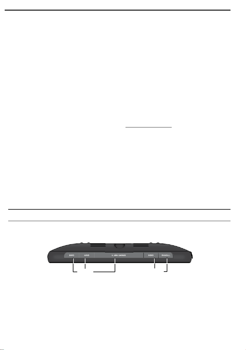
1
.
[ BARO ] key
2 . [ WIND ] key
3 . [ ALARM / SNOOZE ] key
4 . [ INDEX ] key
5 . [ RAINFALL ] key
Page 4
4
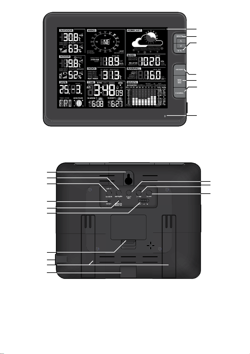
6 . LCD display
13
14
15
16
17
18
19
20
21
22
23
24
25
6
7
8
9
10
11
12
7 . [ GRAPH / Λ ] key
8
.
[ °F / °C / V ] key
9
.
[ HISTORY ] key
10 . [ MAX / MIN ] key
11 . [ CHANNEL ] key
12 . Status LED
13 . Wall mounting holder
14 . [ REFRESH ] key
15 . [ Wi-fi / SENSOR ] key
16 . [ CLOCK SET ] key
17 . [ ALARM ] key
18 . [ ALERT ] key
19 . [ RESET ] key
20 . [ RESCAN ROUTER ] key
21 . Backlight dimmer sliding
switch (Off / Lo / Hi)
22 . Battery compartment
23 . USB socket (for firmware
update only)
24 . Table stand
25 . Power jack
Page 5
5
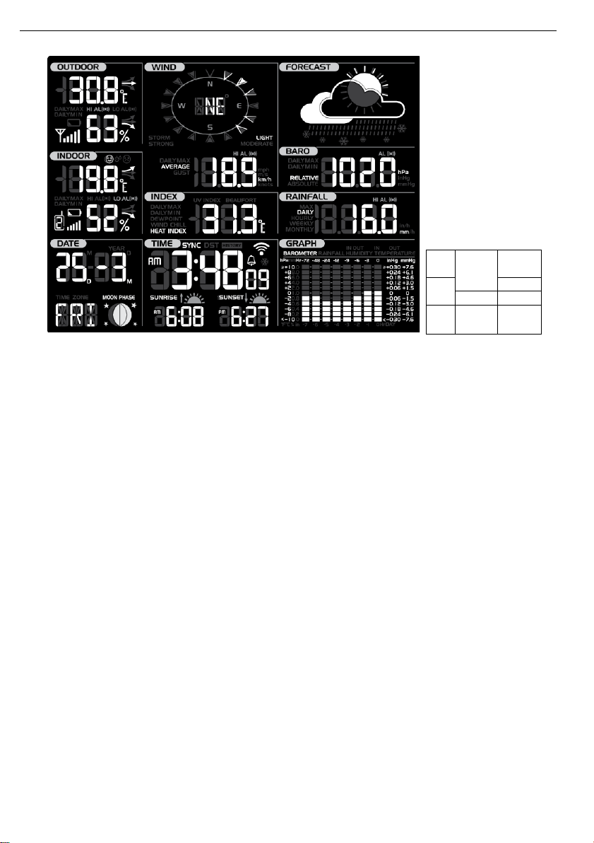
LCD DISPLAY
1
4
7
2
8
5
9
3
6
10
1 . Outdoor temperature & humidity
2 . Indoor temperature & humidity
3 . Calendar & moon phase
4 . Wind direction & speed
5 . Weather index
6 . Time, sunrise/sunset & system status
7 . Weather forecast
8 . Barometer
9 . Rainfall
10 . Multi-function historical bar cha
Page 6
6
INSTALLATION AND SETUP
WIRELESS INDOOR SENSOR
Pairing the wireless Indoor sensor with the console
1 . Remove the battery door of the sensor
2 . Insert 2 x AA size batteries into the battery compartment . Make sure you insert them the
right way according to the polarity information marked on the battery compartment
3 . Close the battery door. The transmission status LED will begin to flash every 1 minute.
Note:
-
If you need to re-assign the sensor channel, firstly slide the channel slide switch to the
new channel that you decided, then press [ SENSOR ] key on the console, and then press
[RESET ] key on the sensor to pair the sensor with the console again
-
Avoid placing the sensors in direct sunlight, rain or snow
-
To avoid the sensor/s and console pairing failure during new console setup, please power
up the sensor/s first, and then press [ RESET ] key on the main unit
(no need on sensors)
Placing the wireless Indoor sensor
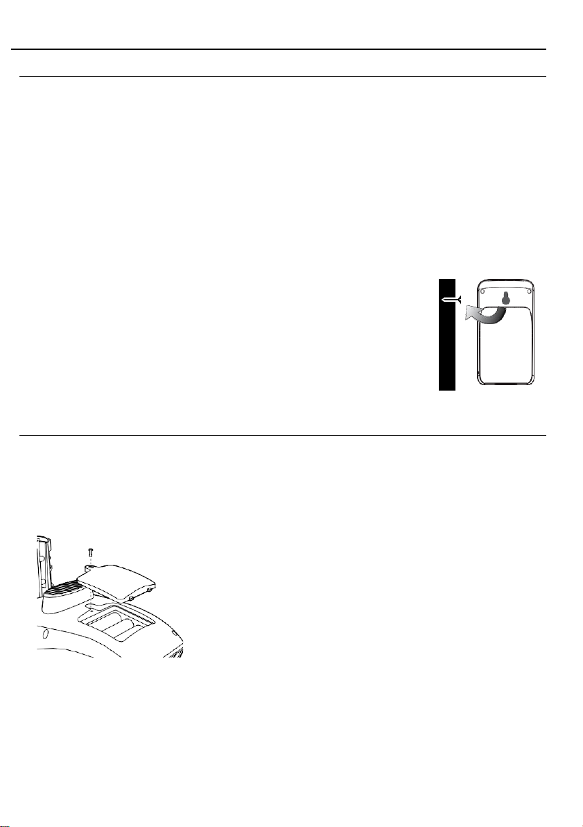
Place a screw on the wall that you wish to hang the sensor on . Hang
the sensor onto the screw by the wall mounting holder . You can also
place the sensor on a table by itself
WIRELESS OUTDOOR SENSOR
Your wireless outdoor sensor measures wind-speed, wind-direction, rainfall, UV index,
temperature and humidity for you
Pairing the wireless outdoor sensor with the console
Installing the wireless outdoor sensor
Install the wireless outdoor sensor to an open location with no obstructions above and around
the sensor for accurate rain and wind measurement
.
.
1 . Unscrew the battery door at the bottom of the unit and
2 . Screw on tightly
3 . Once the batteries are installed, the transmission status
Note:
-
-
.
.
.
.
.
insert the batteries according to the polarity information
marked on the battery compartment
.
LED will begin to flash.
Ensure the battery door screw locked well
Ensure the transmission status LED is flashing every 12
seconds .
.
.
.
Page 7
7
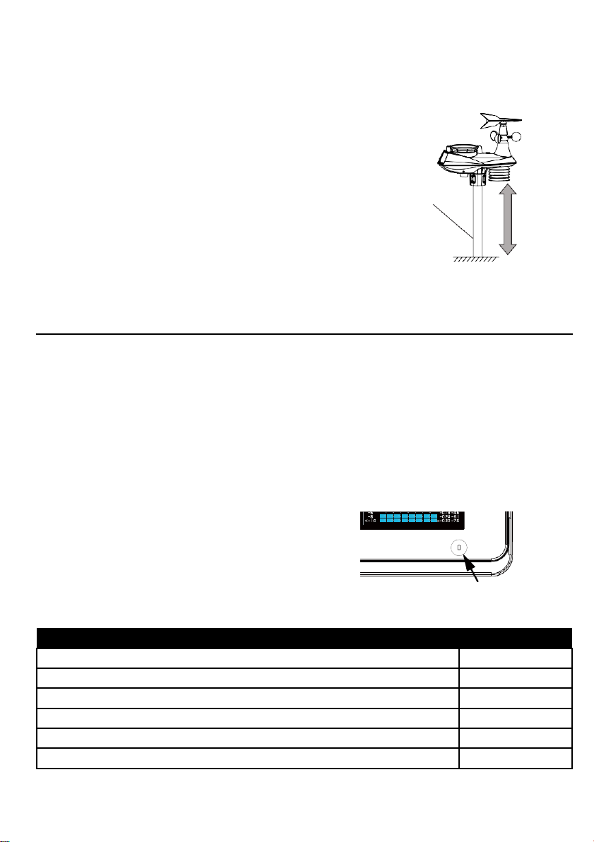
Mounting guideline
Status LED status
AP mode for setup
Flash green light
Connected to Wi-fi router
Blue light
Search the Wi-fi router and fail connection
Flash blue light
Firmware update
Flash red light
Manual sensor pairing mode by pressing [ Wi-fi / SENSOR ] key
Flash cyan light
Refresh the upload data and sync internet time by press [ Refresh ] key
Flash purple
1 . Install the sensor at least 1 .5m off the ground for better
and more accurate wind measurements
.
2 . Choose an open area within 150 meters from the main
console
.
3 . Install the sensor as level as possible to achieve
accurate rain and wind measurements . Use the level
indicator on the sensor to ensure a level installation
4 . Mount the sensor with the wind meter end pointing to
North to correctly orient the direction of the wind vane
.
.
Mountin
g pole
and
stand
(not
included
At least
1.5m
from
ground
)
MAIN CONSOLE
Backup battery installation
1 . Remove the battery door of the main console
2 . Insert 3 new AAA batteries
3 . Close the battery door
.
.
.
Powering up the console
1 . Plug the adaptor into the DC jack
2 . Press [ RESET ] key to re-start the console
.
.
3 . After reset, all LCD segments will show . The console will enter AP (access point) mode and
the status LED will turn on green
.
The Console status LED can show the following status:
LED
Page 8
8
Note:
Backup item list
- Time & Date
-
Bar chart records
By battery backup
- Max/Min records
-
Past 24 hours weather
- Alert setting values
history data records
- Router setting
-
Latitude and longitude
By built-in memory backup
- Weather server setting
-
Time Zone offset
- Time server link
-
Channel history
This console has a dual backup system which allows you to backup different settings and
history records
.
Setting the console's time zone
This weather station console will synchronize the clock with the UTC time server once you set
the time server and connected to the internet . In order to display the correct time and activate
the sunrise/sunset function, you need to set the correct time zone:
1 . Press and hold [ CLOCK SET ] key for 2 seconds to enter time zone setting in time setting
mode
.
2
.
Press [ ] or [ ] key to select the correct time zone
3 . Press [ CLOCK SET ] key again to enter the next setting
4
.
The setting sequence: Time zone → DST ON/OFF → Hour → Minute → Second → 12/24
.
.
hour format → Year → Month → Date → M-D/D-M format → TIME SYNC ON/OFF →
Language
5 . Press [ CLOCK SET ] key to save and exit the setting mode, or the unit will automatically
exit the setting mode 60 seconds later without pressing any button
.
Pairing the wireless indoor and outdoor sensors with the console
The console will automatically search and connect to your wireless indoor and outdoor sensor
You can also press [ Wi-fi / SENSOR ] key to search for your sensors manually . Once your
sensors pair up successful, the sensor signal strength indication and weather information will
appear on your console display
.
Note:
The status LED will flash cyan light, once you press [ Wi-fi / SENSOR ] key to search the
sensors manually
.
CREATE A WUNDERGROUND ACCOUNT AND SETUP WI-FI CONNECTION
A. Register your Wi-fi personal weather station (PWS)
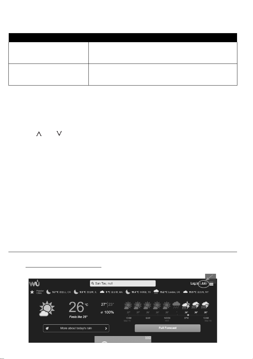
1 . In https://www.wunderground.com click on the "Join" button on the top right corner to open
the registration page . Follow the instructions to create your account
.
.
Page 9
9
Step 2
Note:
You need to validate your email address before you can register your weather station . Click
“Send Validation Email” to receive an email from wunderground.com that contains a validation
link. Click on the link to finish the validation.
2 . After you have created your account and completed the Email validation, please go back to
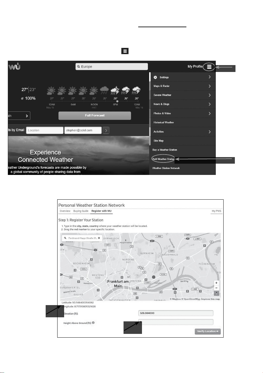
the WUndergound web page . Click “ ” button on the top right corner to open the dropdown menu and select “Add Weather Station” to create your station ID
.
3 . Pin the location on the map . Enter the height above ground of the wireless outdoor sensor
you installed . Jot down the longitude/latitude value for the further setup step
.
Step 1
Page 10
10
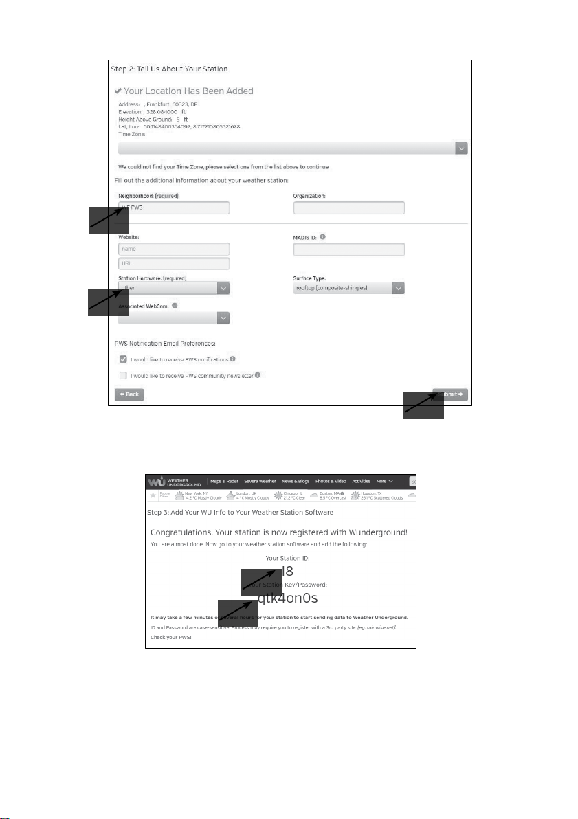
4 . Enter a name for your PWS, then choose “Other” for “Station Hardware” . Once you have
completed, click “Submit”
.
5 . Jot down Your Station ID and Station key for the further setup step
.
Page 11
11
B. Setup the Wi-fi Console to transmit weather data to wunderground.com
Language:
1 . When you plug the adaptor into the DC jack to power up the Wi-fi console during the first
time start up, or press and hold the [ Wi-Fi / SENSOR ] key for 6 seconds in normal mode,
the Status LED on the main console will flash green light to signify that it has entered into
the AP mode, in which the console is ready for the Wi-fi setup.
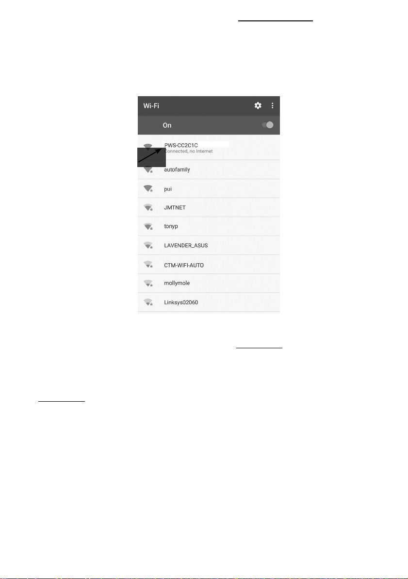
2 . Use your Wi-fi enabled smart phone or computer device to directly connect to the console’s
SSID: PWS-XXXXXX
.
3 . Once connect, open the internet browser and enter 192.168.1.1 into the URL blank, then
press the Enter key to access the console’s setup interface.
Note:
- Since different web browsers are slightly different, please make sure you enter the
192.168.1.1 in the URL blank
.
4 . Fill in the connection information for the setup interface . Your PWS will base on this
information to connect the Wi-fi router.
Note:
-
Depending on your web browser, the layout of the setup interface will be a bit different
-
To find your latitude and longitude, visit Google Maps and directly click on the location that
you want to check and the latitude and longitude will be shown (negative value of latitude
represents South, negative value of longitude represents West)
.
.
Page 12
12
5 . Click “Apply” to finish the setup. If all the information you entered is correct, the setup
Supported device
Built-in Wi-fi with AP mode function smart devices, laptops or PCs:
Android smartphone, Android pad, iPhone, iPad or Windows laptop
Wi-fi standard
802 .11 b/g/n, supports AP mode
Web browser
Browsers that support HTML 5, such as the latest version of Chrome,
Safari, IE, Edge, Firefox or Opera
Wi-fi standard
802 .11 b/g/n
Security type supported
WEP/ WPA / WPA2 / open (for routers with no password)
interface will show as the following. If it does not change, check and fill in the missing
information
.
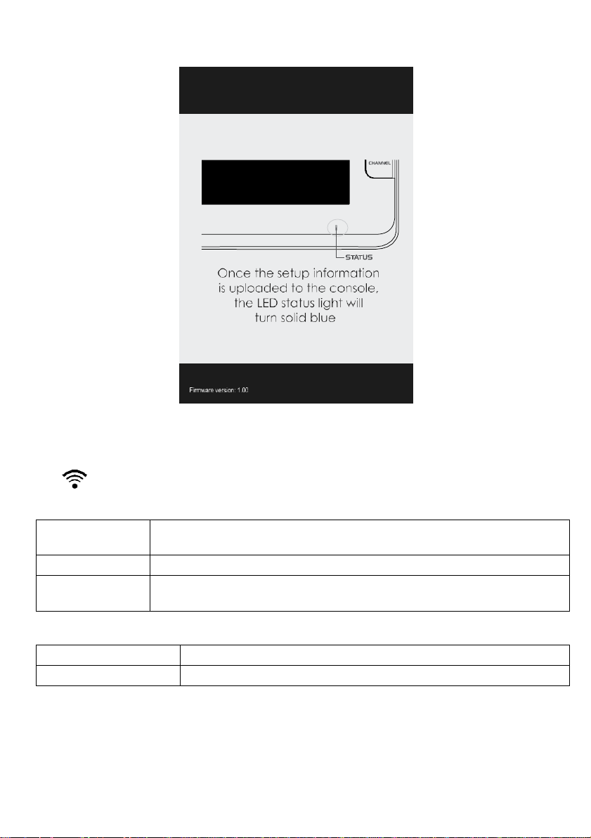
Once the setup is completed, the Wi-fi console will disconnect the Wi-fi connection with your
smart phone or computer and start to search for the router that you have assigned . If the
connection is successful, the status LED of the Wi-fi console will change to blue and the Wi-fi
icon will show on the LCD without flashing.
Wi-fi setup device requirements
Router requirements
Page 13
13
VIEWING LIVE WEATHER DATA
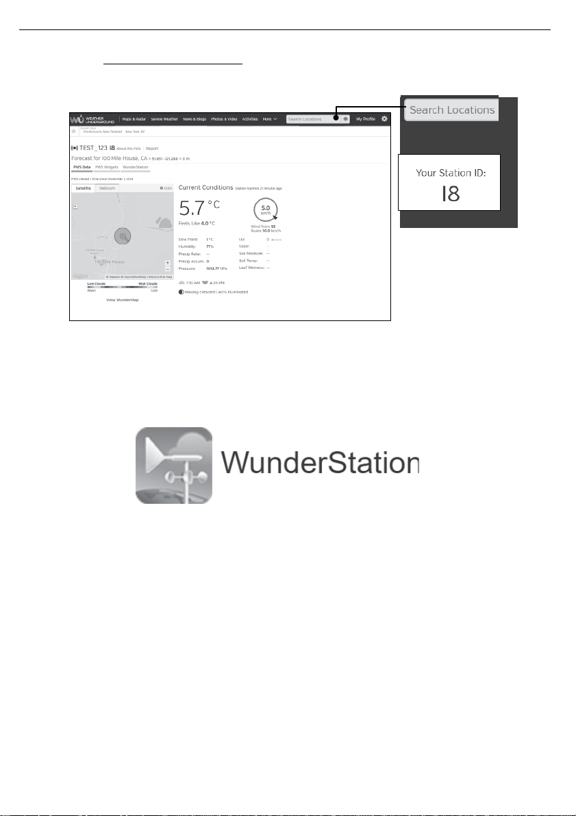
1 . To view the wireless outdoor sensor's live data in a web browser (PC or mobile version),
please visit www .wunderground.com, and then, In the menu bar, enter your “station ID” in the
searching box . The weather information will show up on the next page
2 . You can also use the Apple ipad's "WunderStation" app to login your own weather station and
view your CH 1 wireless Indoor sensor's temperature and humidity live data
.
.
Page 14
14
OPERATION AND OTHER SETTING OF THE CONSOLE
Northern hemisphere
Moon Phase
Southern hemisphere
New Moon
Waxing Crescent
First quarter
Waxing Gibbous
Full Moon
Waxing Gibbous
Third quarter
Waxing Crescent
TIME & DATE, MOON PHASE, SUNRISE & SUNSET
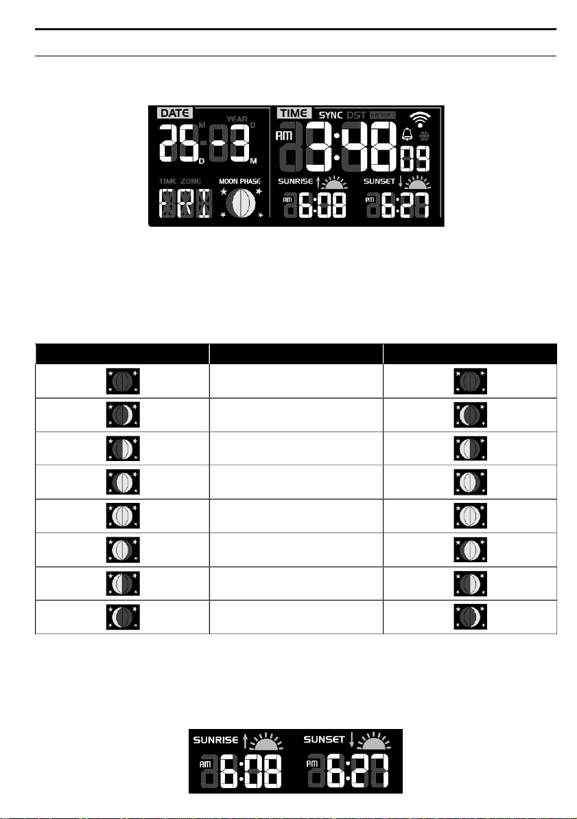
The TIME and DATE information windows locate at the bottom left of the console display . You
can view all the time related information and console status in these two sections
.
Moon Phase
The moon phase is determined by the time, date and time zone . The following table explains
the moon phase icons of the Northern and Southern hemispheres . Please refer to ORIENTING
THE 6-IN-1 SENSOR TOWARDS SOUTH section about how to setup for the Southern
hemispheres
.
Sunrise & Sunset Time
The console indicates your location’s sunrise & sunset time by the time zone, latitude and
longitude you entered . Please insert the correct information in the regarding settings . If the
latitude and longitude values do not match the time zone, the sunrise & sunset time cannot be
shown
.
Page 15
15
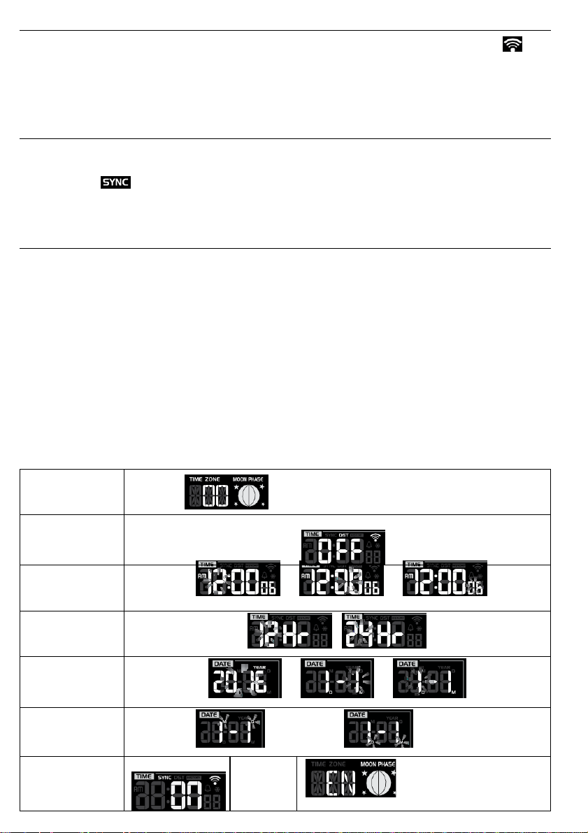
Wi-fi CONNECTION STATUS
TIME ZONE
setting
00H → 01H...23H → -23H...-01H → 00H
DST ON/OFF
setting
Hour > Minute >
Second setting
→ →
12/24Hr setting
/
Year > Month >
Day setting
→ →
M-D/D-M setting
Month-Day / Day-Month
Internet time
sync
Language
EN ↔ FR ↔ DE ↔ ES ↔
IT ↔ NL ↔ RU ↔ EN
As soon as the console successfully connects to the Wi-fi router, the Wi-fi signal icon “ ”
will appear on the LCD display. If the Wi-fi signal is not stable or the console is trying to connect
to the router, the icon will flash.
If the icon disappears, it means the console cannot connect to the Wi-fi router or enter the AP
mode .
TIME SERVER CONNECTION STATUS
After the console has connected to the internet, it will attempt to connect to the internet time
server to obtain the UTC time . Once the connection succeeds and the console's time has been
updated, the “ ” icon will appear on the LCD . The time will automatically synchronize
Internet time server at 12:00AM and 12:00PM per day . Also you can press the [ REFRESH ]
key to get the internet time manually within 1 minute
.
SETTING DATE & TIME
Wi-fi Weather Station is designed to obtain the local time from and to synchronize with the
assigned internet time server. If you want to use this device offline, you can set the time and
date manually
.
1 . In normal mode, press and hold [ CLOCK SET ] key for 2 seconds to enter date and time
setting mode
.
2 . Press [ GRAPH / Λ ] or [ °F / °C / V ] key to adjust the value, or press and hold to change
rapidly
.
3 . While in date and time setting mode, press [ CLOCK SET ] key to switch to the next
setting
.
4 . The setting sequence is: Time Zone → DST ON/OFF → Hour → Minute → Second →
12/24Hr → Year → Month → Day → M-D/D-M → Internet time sync ON/OFF → Language
5 . After completing the language setting, press [ CLOCK SET ] key to save and exit the
setting mode
.
Page 16
16
SETTING ALARM TIME
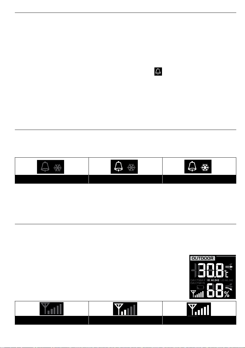
Alarm with ice-alert
Alarm on
Alarm off
No signal
Weak signal
Good signal
1 . In normal time mode, press and hold [ ALARM ] key for 2 seconds until the alarm hour digit
flashes to enter alarm time setting mode.
2 . Press [ GRAPH / Λ ] or [ °F / °C / V ] key to adjust the value, or press and hold to change
rapidly
.
3 . The setting sequence is: Hour → Minute
4 . After completing the minute setting, press [ ALARM ] key to save and exit the setting mode
Note:
-
The alarm will automatically be turned on with the icon “ ” displays after you set
the alarm time
-
Press [ ALARM / SNOOZE ] key to stop the current alarm and enter snooze . The alarm
icon will flash continuously. The alarm will sound again after 5 minutes. Snooze can be
operated continuously in 24 hours
-
When the alarm sounds, it will stop automatically without pressing any button in 2 minutes
Also, you can press and hold the [ ALARM / SNOOZE ] key for 2 seconds or press
[ALARM ] key to stop the current alarm . The alarm will repeat in the next day
ACTIVATING ALARM AND TEMPERATURE PRE-ALARM FUNCTION
1 . In normal mode, press [ ALARM ] key to show the alarm time for 5 seconds
2 . When the alarm time displays, press [ ALARM ] key again to activate the alarm function
Or press [ ALARM ] key twice to activate the alarm with ice pre-alarm function
.
.
.
.
.
.
.
.
.
Note:
Once the ice pre alert activates, the preset alarm will sound 30 minutes earlier if the outdoor
temperature is below -3°C
INDOOR AND OUTDOOR TEMPERATURE & HUMIDITY
You can view the in/outdoor channels' temperature & humidity readings and the related
information at the top-left or middle left column of the LCD
Note:
In normal mode, press [ °F / °C / V ] key to switch between °C/°F
The OUTDOOR Window
The OUTDOOR window displays the thermo-hygro readings of wireless
outdoor 6-in-1 weather sensor
Wireless outdoor sensor signal strength:
Note: Please locate the console where can receive good sensor signal
.
.
.
.
.
Page 17
17
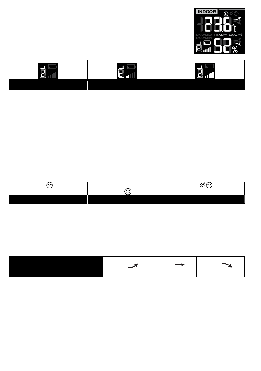
The INDOOR Window
Too cold
Comfortable
Too hot
Arrow indicator
Temperature / Humidity trend
Rising
Steady
Falling
Good signal
Weak signal
No signal
The INDOOR window displays the thermo-hygro reading of wireless
indoor thermo-hygro sensor(s) (Ch .1 -Ch .7)
Wireless Indoor sensor signal strength:
Note: Please locate the sensors where console can receive good signal
Viewing Different Indoor Channel
This console is capable to pair with up to 7 wireless indoor thermo-hygro sensors . If you have 2
or more sensors, you can press [ CHANNEL ] key to switch between different indoor channels
in normal mode, or press and hold [ CHANNEL ] key for 2 seconds to toggle auto-cycle mode
to display the connected channels at 4 second intervals
During auto-cycle mode, press [ CHANNEL ] key to stop the auto cycle and display the current
channel
Comfort Indication
The comfort indication is a pictorial indication based on indoor air temperature and humidity in
an attempt to determine comfort level . Each indoor channel has independent comfort indication
Note:
Comfort indication can vary under the same temperature, depending on the humidity
There is no comfort indication when temperature is below 0°C (32°F) or over 60°C (140°F)
Temperature / Humidity Trend
The temperature / humidity trend indicator shows the trends of changes in the forthcoming few
minutes . Arrows indicate a rising, steady or falling trend
.
.
.
.
.
.
.
Note:
When temperature is below -40°C, the LCD will display “Lo” . If temperature is above 80°C,
LCD will display “HI”
When humidity is below 1%, LCD will display “Lo” . If humidity is above 99%, LCD will display
“HI”
.
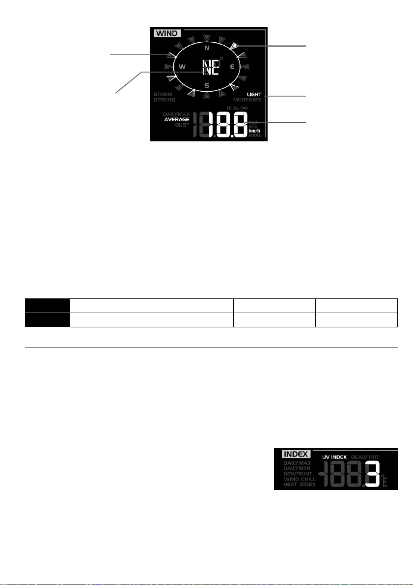
WIND
The wind speed, direction and related information will be displayed in the WIND window at the
top-row-middle
.
.
Page 18
18
Viewing Wind Direction
Level
LIGHT
MODERATE
STRONG
STORM
Speed
0.1km/h ~19km/h
20km/h ~ 49km/h
50km/h ~ 88km/h
> 89km/h
Real time wind
Past wind directions
indicator of last 5
minutes
Wind direction in 360°
or 16-direction
direction indicator
Wind speed level
Average / gust wind
speed
To select the wind display mode
In normal mode, press [ WIND ] key to switch between AVERAGE wind speed and GUST wind
speed
.
To set the wind speed unit and direction display format
1 . In normal mode, press and hold [ WIND ] key for 2 seconds to enter into wind speed unit
mode and the unit will flash. And then press [ GRAPH / Λ ] or [ °F / °C / V ] key to change
the wind speed unit in this sequence: m/s → km/h → knots → mph
2 . Press [ WIND ] key again to enter into wind direction display format setting mode . The wind
direction reading will flash. And then press [ GRAPH / Λ ] or [ °F / °C / V ] key to select the
display format between 360° and 16-direction
3 . Press [ WIND ] key again to return to normal mode
.
.
Wind Speed Level
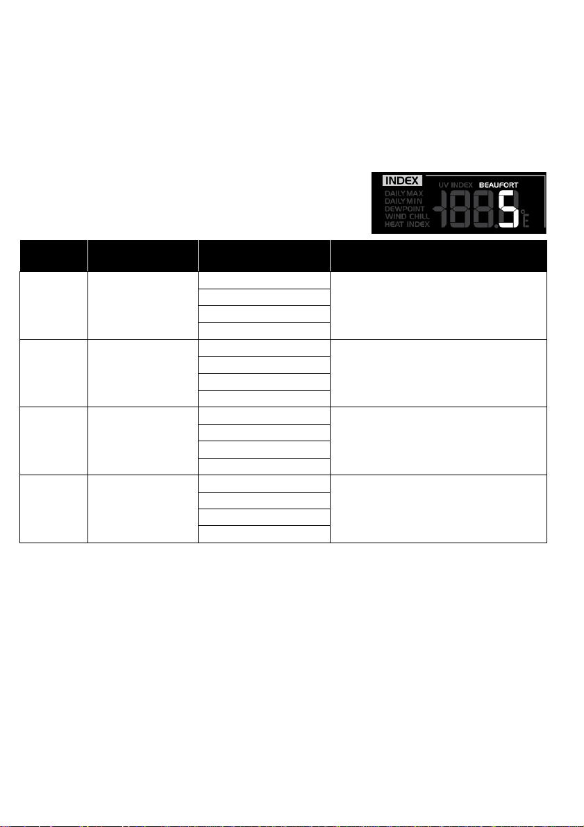
WEATHER INDEX
The weather index window (INDEX), in the middle of the LCD, displays the UV INDEX,
BEAUFORT, WIND CHILL, HEAT INDEX and DEWPOINT
.
In normal mode, press [ INDEX ] key to view the weather indices in this sequence: UV INDEX
→ BEAUFORT → WIND CHILL → HEAT INDEX → DEWPOINT
Note:
In normal mode, press [ °F / °C / V ] key to switch between °C/°F
.
UV Index
The UV index reflects the UV data collected by the wireless
outdoor sensor that the detectable range is 0~16.
Page 19
19
Beaufort
Scale
Description
Wind Speed
Land Condition
0
Calm
< 1 km/h
Calm . Smoke rises vertically
.
< 1 mph
< 1 knots
< 0 .3 m/s
1
Light air
1.1 ~ 5km/h
Smoke drift indicates wind direction
.
Leaves and wind vanes are
stationary
.
1 ~ 3 mph
1 ~ 3 knots
0.3 ~ 1.5 m/s
2
Light breeze
6 ~ 11 km/h
Wind felt on exposed skin . Leaves
rustle . Wind vanes begin to move
.
4 ~ 7 mph
4 ~ 6 knots
1.6 ~ 3.3 m/s
3
Gentle breeze
12 ~ 19 km/h
Leaves and small twigs constantly
moving, light flags extended.
8 ~ 12 mph
7 ~ 10 knots
3.4 ~ 5.4 m/s
1 . In normal mode of the console, press and hold [ INDEX ] key for 10 seconds to enter into
UV index calibration mode
2 . Use [ GRAPH / Λ ] or [ °F / °C / V ] key to adjust the UV gain magnification factor
3 . Press the [ INDEX ] key twice to confirm and exit the setting
Note:
-
The default UV gain magnification factor is 1.0, and can be adjusted up or down in
increments of 0 .1
.
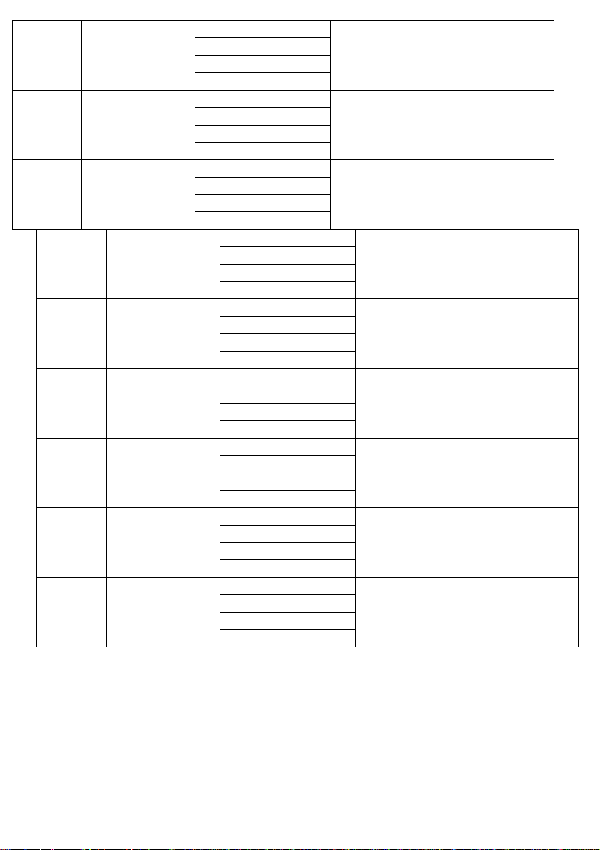
Beaufort Scale
The Beaufort scale is an international scale of wind velocities
ranging from 0 (calm) to 12 (Hurricane force)
.
Page 20
20
4
Moderate breeze
20 ~ 28 km/h
Dust and loose paper raised . Small
branches begin to move
.
13 ~ 17 mph
11 ~ 16 knots
5.5 ~ 7.9 m/s
5
Fresh breeze
29 ~ 38 km/h
Branches of a moderate size move
.
Small trees in leaf begin to sway
.
18 ~ 24 mph
17 ~ 21 knots
8.0 ~ 10.7 m/s
6
Strong breeze
39 ~ 49 km/h
Large branches in motion . Whistling
heard in overhead wires . Umbrella
use becomes difficult. Empty plastic
bins tip over
.
25 ~ 30 mph
22 ~ 27 knots
10.8 ~ 13.8 m/s
7
High wind
50 ~ 61 km/h
Whole trees in motion . Effort needed
to walk against the wind
.
31 ~ 38 mph
28 ~ 33 knots
13.9 ~ 17.1 m/s
8
Gale
62 ~ 74 km/h
Some twigs broken from trees
.
Cars veer on road . Progress on foot
is seriously impeded
39 ~ 46 mph
34 ~ 40 knots
17.2 ~ 20.7 m/s
9
Strong gale
75 ~ 88 km/h
Some branches break off trees,
and some small trees blow over
.
Construction /temporary signs and
barricades blow over
.
47 ~ 54 mph
41 ~ 47 knots
20.8 ~ 24.4 m/s
10 Storm
89 ~ 102 km/h
Trees are broken off or uprooted,
structural damage likely
.
55 ~ 63 mph
48 ~ 55 knots
24.5 ~ 28.4 m/s
11 Violent storm
103 ~ 117 km/h
Widespread vegetation and structural
damage likely
.
64 ~ 73 mph
56 ~ 63 knots
28.5 ~ 32.6 m/s
12
Hurricane force
≥ 118 km/h
Severe widespread damage to
vegetation and structures . Debris and
unsecured objects are hurled about
.
≥ 74 mph
≥ 64 knots
≥ 32.7m/s
Page 21
21
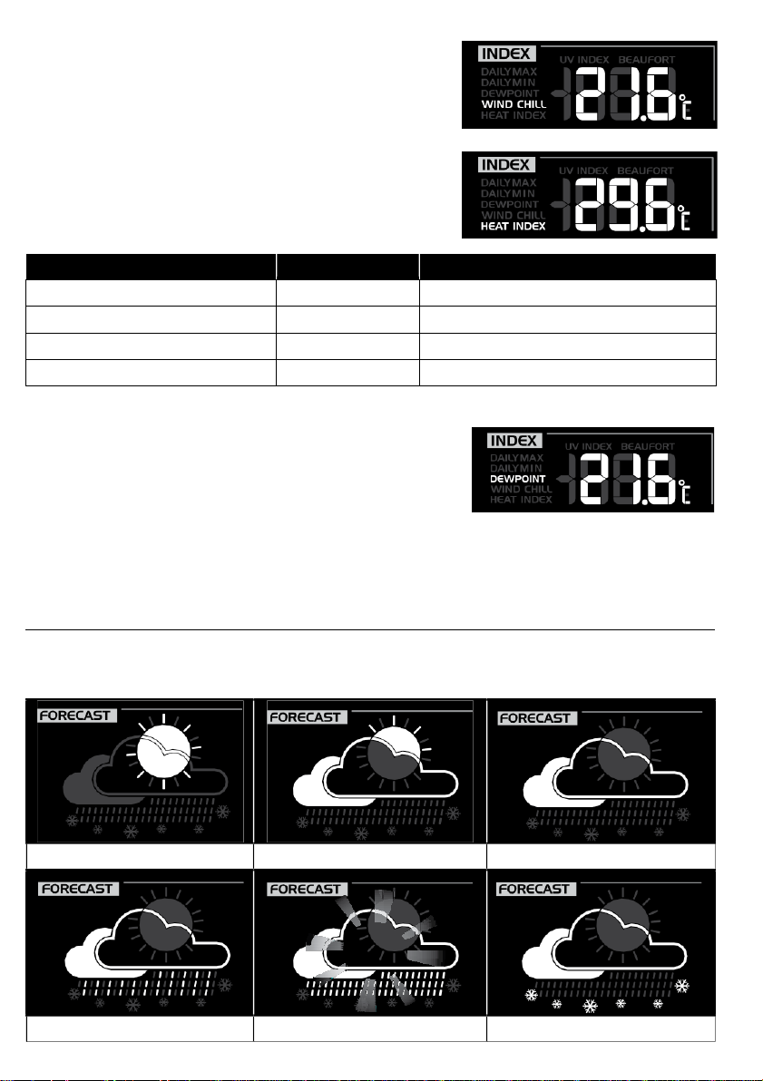
Wind Chill
Heat Index range
Warning
Explanation
27°C to 32°C (80°F to 90°F)
Caution
Possibility of heat exhaustion
33°C to 40°C (91°F to 105°F)
Extreme Caution
Possibility of heat dehydration
41°C to 54°C (106°F to 129°F)
Danger
Heat exhaustion likely
≥55°C (≥130°F)
Extreme Danger
Strong risk of dehydration / sun stroke
Sunny
Slightly cloudy
Cloudy
Rainy
Rainy / Stormy
Snowy
A combination of the wireless outdoor sensor's temperature
and wind speed data determines the current wind-chill
factor
.
Heat Index
The heat index, which is determined by the wireless
outdoor sensor's temperature & humidity data, when the
temperature is between 27°C (80°F) and 50°C (120°F)
.
Dewpoint
-
The dew point is the temperature below which the water
vapor in air at constant barometric pressure condenses
into liquid water at the same rate at which it evaporates
.
The condensed water is called dew when it forms on a
solid surface
-
The dew point temperature is determined by the
.
temperature & humidity data from wireless outdoor
sensor
.
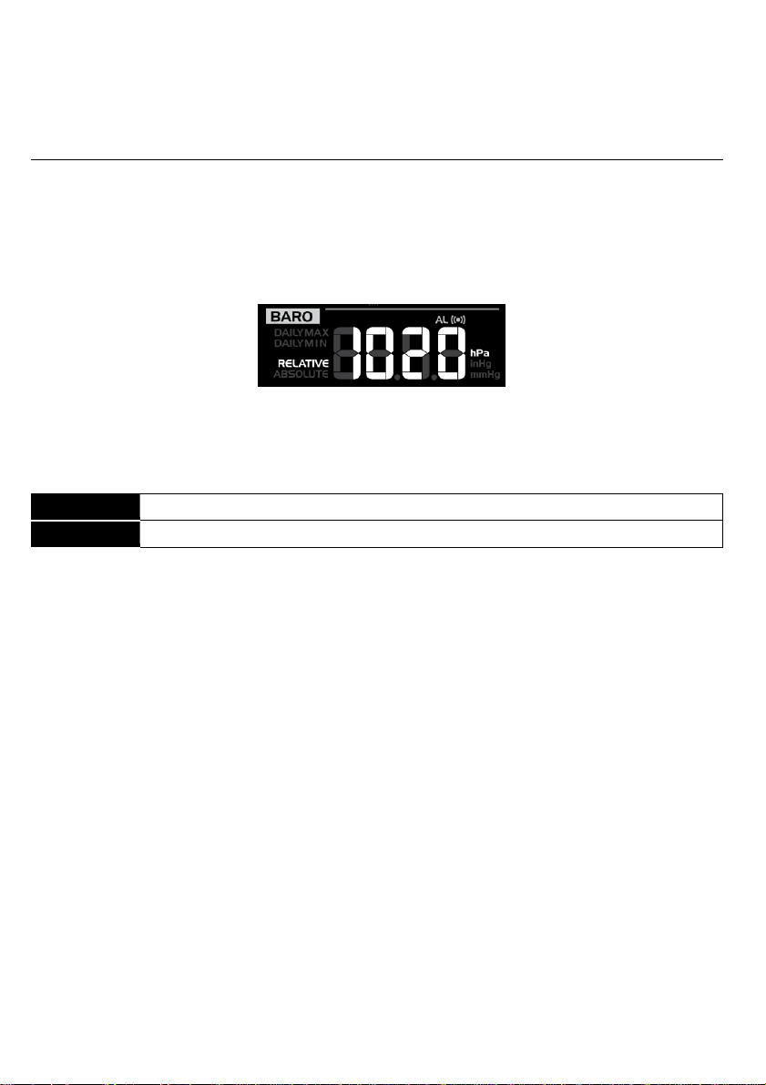
WEATHER FORECAST
The weather forecast window (FORECAST) locates at the upper right corner of the LCD . The
console is built with a sensitive pressure sensor, by which the proven sophisticated software
forecasts the weather of the next 12~24 hours within a 30~50km (19~31 miles) radius.
Page 22
22
Note:
Absolute
The absolute atmospheric pressure of your location
.
Relative
The relative atmospheric pressure based on the sea level
-
The weather forecast is reflecting the weather situation for next 12 hours, it may not
necessarily reflect the current situation.
-
The “Snowy” icon will be displayed when the outdoor temperature is below -3°C (26°F), and
under cloudy or rainy forecast
.
BAROMETRIC PRESSURE
The barometric pressure window (BARO) locates in the middle right of the LCD Barometric
pressure: the atmospheric pressure is the pressure at any location of the Earth caused by
the weight of the column of air above it . One atmospheric pressure refers to the average
pressure and gradually decreases as altitude increases . Meteorologists use barometers to
measure atmospheric pressure . Since variation in atmospheric pressure
greatly affected by weather, it is possible to forecast the weather by measuring the changes in
pressure
.
To set the barometer unit and select the wind display mode
1 . In normal mode, press [ BARO ] key to change the barometer unit in this sequence: hPa
→ inHg → mmHg
2 . In normal mode, press and hold [ BARO ] key to switch between ABSOLUTE/RELATIVE
display .
To set the RELATIVE atmospheric pressure value
1 . Obtain the atmospheric pressure data of the sea level (it is also the relative atmospheric
pressure data of your home area) through the local weather service, internet or any weather
information source
.
2 . In normal mode, press and hold [ BARO ] key for 2 seconds until “ABSOLUTE” or
“RELATIVE” icon flashes.
3 . Press [ GRAPH / Λ ] or [ °F / °C / V ] key to switch to “RELATIVE” mode
.
4 . Press [ BARO ] key once again, the “RELATIVE” atmospheric pressure digit flashes.
5 . Press [ GRAPH / Λ ] or [ °F / °C / V ] key to change its value
6 . Press [ BARO ] key to save and exit the setting mode
.
.
Note:
-
When you change the RELATIVE atmospheric pressure value, the weather indicators will
change along with it
-
The built-in barometer detects the environmental absolute atmospheric pressure changes
.
Based on the data collected, it predicts the weather conditions in the forthcoming 12 hours
The weather indicator will change according to the detected absolute atmospheric pressure
after operating the clock for 1 hour
-
The RELATIVE atmospheric pressure is based on the sea-level pressure you entered but it
will change with the absolute atmospheric pressure after operating the clock for 1 hour
.
.
.
.
Page 23
23
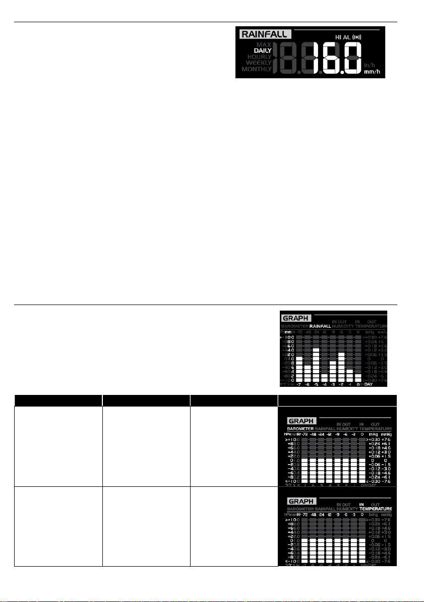
RAINFALL
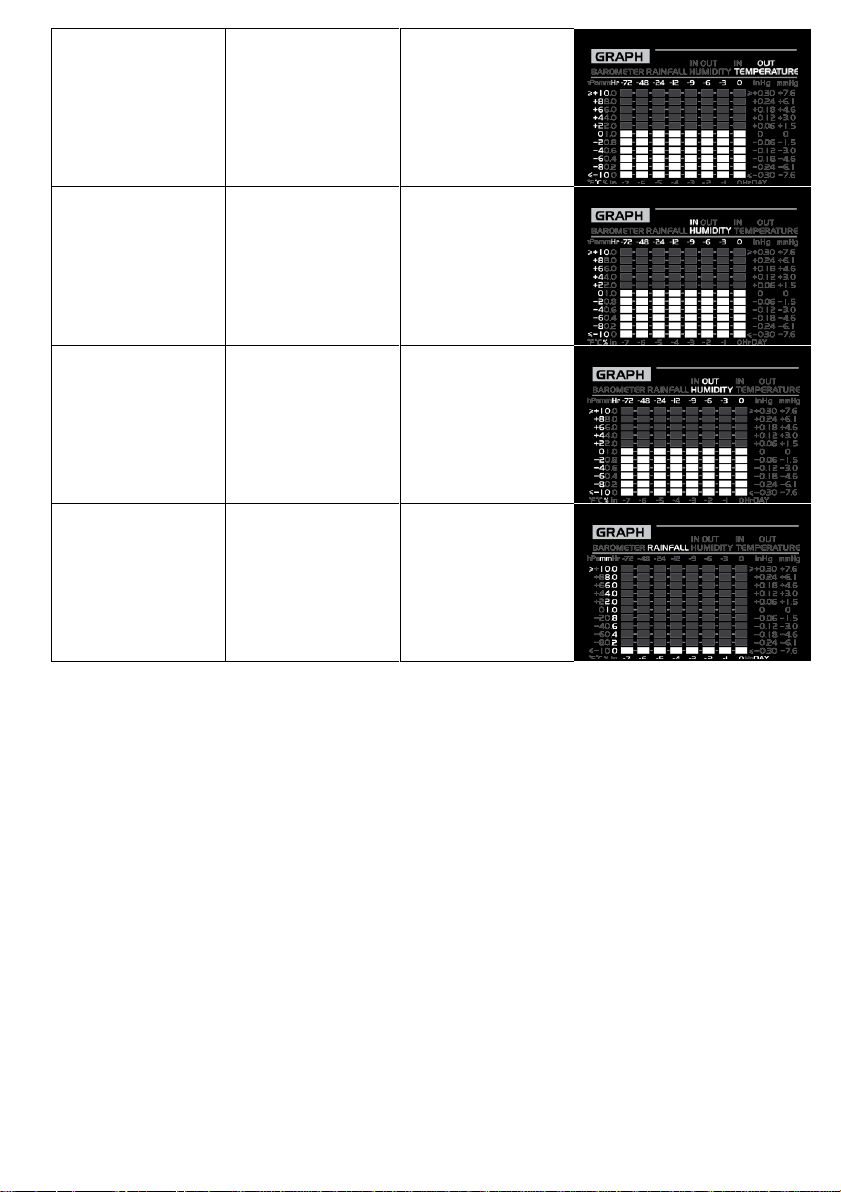
Weather variable
Unit of measure
Record time range
Graph
Barometric
pressure
hPa, inHg and
mmHg
Past 72 hours
Indoor temperature
(according to the
current channel)
°F or °C
Past 72 hours
The RAINFALL reading displays in the middle right
of the LCD . It shows how many mm/inches of rain
have accumulated in the rain collector in one-hour
time period to indicate the current rainfall rate
To set the rainfall unit
1 . Press and hold [ RAINFALL ] key for 2 seconds to enter unit setting mode
2 . Press [ GRAPH / Λ ] or [ °F / °C / V ] key to toggle between mm (millimeter) and in (inch)
3 . Press [ RAINFALL ] key to confirm and exit the setting.
To select the rainfall display mode
Press [ RAINFALL ] key to toggle between:
1 . DAILY - the total rainfall from midnight
2 . HOURLY - the total rainfall in the past hour
3 . WEEKLY - the total rainfall of the current week
4 . MONTHLY- the total rainfall of the current calendar month
5 . Accumulate - the total rainfall since the last reset
Note:
-
In normal mode, press and hold [ HISTORY ] key for 2 seconds to reset the Accumulate
rainfall record
-
To avoid the fault data, please reset the Accumulate rainfall when you reinstall your
wireless outdoor sensor to other location
HISTORY GRAPH
The history graph (GRAPH), at the bottom right of the LCD,
displays different weather histories in bar chart format .
To view different graphs
In normal mode, press [ GRAPH / Λ ] key to toggle between
different types of graph:
.
.
.
.
Page 24
24
Outdoor
temperature
°F or °C
Past 72 hours
Indoor humidity
(according to the
current channel)
%
Past 72 hours
Outdoor humidity
%
Past 72 hours
Rainfall
mm or in
Past 7 days (daily)
To view the daily MAX/MIN
The console can record the daily MAX/MIN weather data for your easy review
-
In normal mode, press [ MAX / MIN ] key to check the daily MAX/MIN records . The display
.
sequence is: outdoor MAX temperature & humidity → outdoor MIN temperature & humidity
→ current channel’s indoor MAX temperature & humidity → current channel’s indoor MIN
temperature & humidity → MAX average wind speed → MAX gust → MAX dew point →
MIN dew point → MAX wind chill → MIN wind chill → MAX heat index → MIN heat index →
MAX UV index → MAX Beaufort → MAX pressure → MIN pressure → MAX daily rainfall.
-
Press and hold [ MAX / MIN ] key for 2 seconds to reset all the MAX/MIN records
To view the history data (the records in the past 24 hours)
The console automatically stores the weather data of the past 24 hours
.
1 . Press [ HISTORY ] key to check the beginning of the current hour's weather data, e .g . the
current time is 7:25 am, March 28, the display will show the data of 7:00am, March 28
2 . Press [ HISTORY ] key repeatedly to view older readings of the past 24 hours, e .g . 6:00am
(Mar 28), 5:00am (Mar 28), …, 10:00am (Mar 27), 9:00am (Mar 27), 8:00am (Mar 27)
Note:
The LCD will display the history data records and their time & date
.
.
.
Page 25
25
WEATHER ALERT SETTING
Alert reading Sequence
Setting Range
Display Section
Default Value
Outdoor Temperature High Alert
-40°C ~ 80°C
Outdoor temperature &
humidity section
(OUTDOOR)
40°C
Outdoor Temperature Low Alert
0°C
Outdoor Humidity High Alert
1% ~ 99%
80%
Outdoor Humidity Low Alert
40%
Indoor Temperature High Alert
-40°C ~ 80°C
Current Indoor
temperature & humidity
section
(INDOOR)
40°C
Indoor Temperature Low Alert
0°C
Indoor Humidity High Alert
1% ~ 99%
80%
Indoor Humidity Low Alert
40%
Wind Speed
0.1m/s ~ 50m/s
Wind direction & speed
section (WIND)
17 .2mm/h
Pressure Drop (within 30
minutes)
1hPa ~ 10hPa
Barometer section
(BARO)
3hPa
Daily Rainfall
1mm ~
1000mm
Rainfall section
(RAINFALL)
100mm
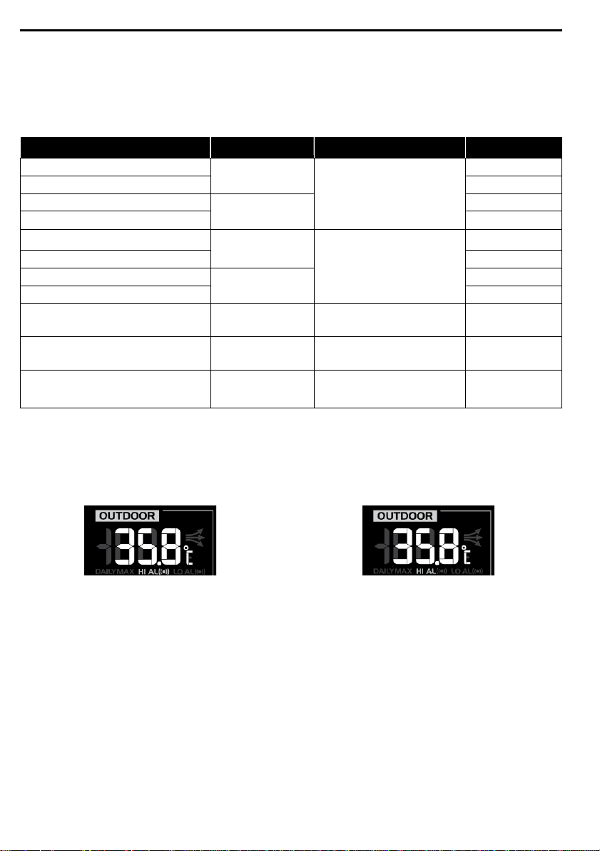
Weather Alert can alert you of certain weather conditions . Once the alert criterion is met, the
alarm sound will activate and the LCD’s alert icon will flash.
To set alert
1 . Press [ ALERT ] to select and display the desired weather alert reading in the sequence
below:
2 . Under the current alert reading, press and hold [ ALERT ] key for 2 seconds to enter alert
setting and the alert reading will flash.
3 . Press [ GRAPH / Λ ] or [ °F / °C / V ] key to adjust the value or press and hold the key to
change rapidly
.
4 . Press [ ALERT ] key to save the alert reading then press [ ALARM ] key to toggle the
regarding alert on/off
.
Alert on Alert off
5 . Press any key on the front side to save and back to normal mode, or it will automatically
back to normal mode after 30 seconds without pressing any key
.
To silence the alert alarm:
Press [ ALARM / SNOOZE ] key to silence the alert alarm or let the alarm automatically turn off
after 2 minutes
.
Note:
-
Once the alert is triggered, the alarm will sound for 2 minutes and the related alert icon will
flash.
-
If the alert alarm is automatically off after 2 minutes, the alert icon will stop flashing.
-
The weather alert will sound again when the weather readings falls into the alert range
again
.
Page 26
26
POINTING THE 6-IN-1 SENSOR TO SOUTH
2 1 2
The outdoor 6-in-1 sensor is calibrated to point to North for the maximum accuracy . However,
for the user's convenience (e .g . users in the Southern hemisphere), it is possible to use the
sensor with the wind vane pointing to South
1 . Install the wireless outdoor sensor with its wind meter end pointing to South . (Please refer
to INSTALLATION OF THE WIRELESS OUTDOOR SENSOR for mounting details)
2 . In normal mode of the console, press and hold [ INDEX ] key for 8 seconds to enter into the
UV index calibration mode, then press the index again until the “N” icon appears on the
weekday location to enter into the sensor orientation mode
3 . Use [ GRAPH / Λ ] or [ °F / °C / V ] key to change to lower part (Southern Hemisphere)
4 . Press [ INDEX ] key to confirm and exit.
5 . Press the [ REFRESH ] to synchronize the internet time after you complete the setting
Note:
-
Changing the hemisphere setting will automatically switch the direction of the moon phase
on the display
MAINTENANCE
BATTERY REPLACEMENT
When the low battery indicator “ ” displays, it indicates that the wireless outdoor 6-in-1
weather sensor or the current channel wireless Indoor thermo-hygro sensor battery power is
low . You should replace with fresh AA size batteries at once
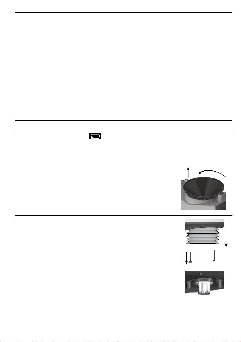
CLEANING THE RAIN COLLECTOR
1 . Unscrew the rain collector by turning it 30°anticlockwise
2 . Gently remove the rain collector
3 . Clean and remove any debris or insects
4 . Install the collector when it is clean and fully dried
CLEANING THE HYGRO-THERMO SENSOR OF THE WIRELESS OUTDOOR SENSOR
1 . Remove the 2 screws at the bottom of the radiation shield
2 . Gently pull out the shield
3 . Carefully remove any dirt or insects on the sensor casing (do not
let the sensors inside get wet)
4 . Clean the shield with water to remove any dirt or insects
5 . Install all the parts back when they are clean and fully dried
.
.
.
.
.
.
.
.
.
.
.
.
1
.
Page 27
27
CLEANING THE UV SENSOR AND CALIBRATION
Clean the UV sensor cover lens
For precision UV measurement, gentle clean the UV sensor cover lens by the pure water
regularly
UV Sensor Degradation
Over time, the UV sensor will naturally degrade . The UV sensor can be calibrated with a utility
grade UV meter
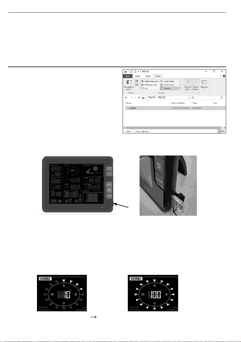
CONSOLE FIRMWARE UPDATE
1
2 . Copy the unzipped “Update” folder to the
Important note:
3
.
.
.
Unzip the “Update.zip” file
USB mass storage driver
-
The USB mass storage driver should be
FAT32 format
-
The “Update” folder must be the USB mass
storage driver’s root directory)
.
Disconnect the main console’s DC power from the power outlet and remove the backup
batteries . Plug the USB mass storage driver to the USB socket at the right side of the main
console
.
.
4 . Reconnect the main console’s DC power to start the update process
Important note:
-
In the meantime, do not remove the USB mass storage driver
-
If the firmware update still not restart, you can try to press the reset key to trigger the
update process
5 . During the update process, the Console status LED will flash in red color and LCD will show
the update status as below:
.
Updating screen Update completed and waiting for reboot
.
Page 28

28
6 . Once the update completed, the main console will restart and return to the normal display
screen
.
7 . Remove the USB mass storage driver from the main console
8 . Set the time zone on the main console
.
9 . Enter the WU connection information and set time server in the setup UI
.
.
Note:
-
The USB port is for firmware update only.
-
Please keep connect the power during the firmware update process.
-
During firmware update process the Wi-fi will be disable until the update success and it will
reconnect to your Wi-fi router and upload the data again. If the console cannot connect to
your route, you need to re-enter the router and WU connection information and set time
server in the setup UI again
.
PRECAUTIONS
-
Read and keep these instructions
-
Do not subject the unit to excessive force, shock, dust, temperature or humidity
-
Do not cover the ventilation holes with any items such as newspapers, curtains etc
-
Do not immerse the unit in water . If you spill liquid over it, dry it immediately with a soft, lintfree cloth
-
Do not clean the unit with abrasive or corrosive materials
-
Do not tamper with the unit’s internal components. This invalidates the warranty.
-
Only use fresh batteries . Do not mix new and old batteries
-
Only use attachments / accessories specified by the manufacturer.
-
Images shown in this manual may differ from the actual display
-
When disposing of this product, ensure it is collected separately for special treatment
-
Placement of this product on certain types of wood may result in damage to its finishing
.
.
.
.
.
.
for which manufacturer will not be responsible. Consult the furniture manufacturer’s care
instructions for information
-
The contents of this manual may not be reproduced without the permission of the
manufacturer
-
When replacement parts are required, be sure the service technician uses replacement
.
.
parts specified by the manufacturer that have the same characteristics as the original parts.
Unauthorized substitutions may result in fire, electric shock, or other hazards.
-
Do not dispose old batteries as unsorted municipal waste . Collection of such waste
separately for special treatment is necessary
-
The socket outlet shall be installed near the equipment and shall be easily accessible
-
Technical specifications and user manual contents for this product are subject to change
without notice
-
Place the main console at least 20cm from nearby persons
.
.
.
.
.
.
Page 29
29
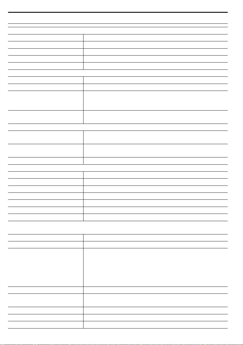
SPECIFICATION
Dimensions (W x H x D)
215 x 172 x 29mm (8 .5 x 6 .8 x 1 .1in)
Weight
639g (with batteries)
Main power
DC 5V, 1A adaptor
Backup battery
3 x AAA size 1 .5V batteries (alkaline recommended)
Operating temperature range
-5˚C ~ 50˚C
Wi-fi standard
802 .11 b/g/n
Wi-fi operating frequency :
2 .4GHz
Supported device for setup UI
Built-in Wi-fi with AP mode function smart devices, laptops
or PCs: Android smart phone, Android pad, iPhone, iPad or
Windows laptop
Recommended web browser
for setup UI
Web browsers that support HTML 5, such as the latest
version of Chrome, Safari, IE, Edge, Firefox or Opera
.
Support sensors
1 Wireless 6-in-1 weather outdoor sensor and up to 7
Wireless hygro-thermo indoor sensors
RF frequency
915Mhz (US version) / 868Mhz (EU or UK version) /
917Mhz (AU version)
RF transmission range
150m
Time display
HH: MM: SS
Hour format
12hr AM/PM or 24 hr
Date display
DD / MM or MM / DD
Time synchronize method
Through Internet time server to synchronize the UTC
Weekday languages
EN / DE / FR / ES / IT / NL / RU
Hour offset
+13 ~ -12 hour
DST
ON / OFF
Barometer unit
hPa, inHg and mmHg
Measuring range
540 ~ 1100hPa (relative setting range 930 ~ 1050hPa)
Accuracy
(700 ~ 1100hPa ± 5hPa) / (540 ~ 696hPa ± 8hPa)
(20.67 ~ 32.48inHg ± 0.15inHg) / (15.95 ~ 20.55inHg ±
0 .24inHg)
(525 ~ 825mmHg ± 3.8mmHg) / (405 ~ 522mmHg ±
6mmHg)
Typical at 25°C (77°F)
Resolution
1hPa / 0 .01inHg / 0 .1mmHg
Weather forecast
Sunny/Clear, Slightly Cloudy, Cloudy, Rainy, Rainy / Stormy
and Snowy
Display modes
Current
Memory modes
Historical data of past 24 hours, daily Max / Min
Alarm
Pressure change alert
MAIN CONSOLE
General Specification
Wi-fi Communication Specification
Wireless Sensor side Communication Specification
Time Related Function Specification
Barometer Display & Function Specification
Note: The following details are listed as they are displayed or operate on the console
.
Page 30
30
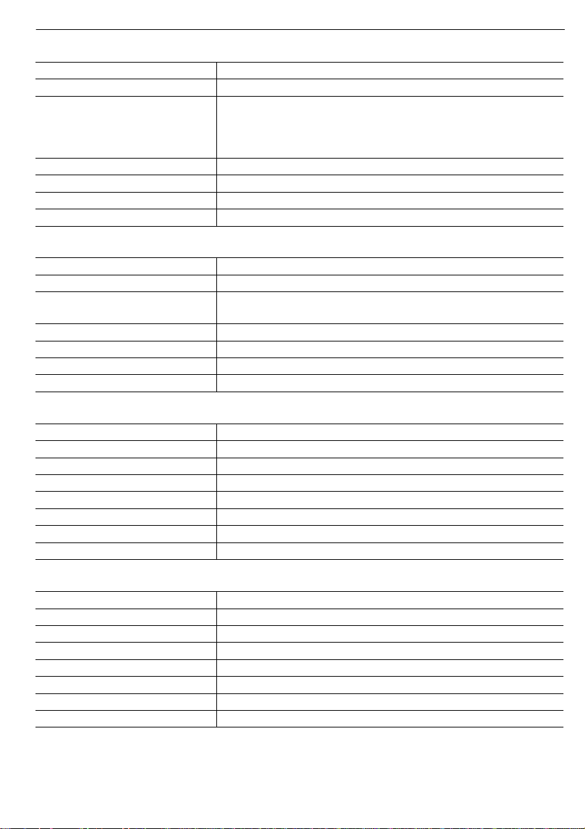
Temperature unit
°C and °F
Display range
-40 ~ 80°C (-40 ~ 176°F)
Accuracy
55 ~ 60°C ± 0.5°C (131 ~ 140°F ± 0.9°F)
10 ~ 55°C ± 0.4°C (50 ~ 131°F ± 0.7°F)
-20 ~ 10°C ± 1.3°C (-4 ~ 50°F ± 2.3°F)
-40 ~ -20°C ± 1.9°C (-40 ~ -4°F ± 3.4°F)
Resolution
0 .1°C / 0 .1°F
Display modes
Current
Memory modes
Historical data of past 24 hours, daily Max / Min
Alarm
Hi / Lo temperature alert
Humidity unit
%
Display range
0 ~ 100%
Accuracy
0 ~ 90% RH ± 2.5% RH @ 25°C (77°F)
90 ~ 100% RH ± 3.5% RH @ 25°C (77°F)
Resolution
1%
Display modes
Current
Memory modes
Historical data of past 24 hours, daily Max / Min
Alarm
Hi / Lo Humidity Alert
Wind speed unit
mph, m/s, km/h and knots
Wind speed display range
0 ~ 112mph, 50m/s, 180km/h, 97knots
Resolution
0 .1mph, 0 .1m/s, 0 .1km/h, 0 .1knots
Speed accuracy
±2.2 mph or ±10% (whichever is greater)
Display mode
Gust/Average
Memory modes
Historical Data of past 24 hours, daily Max Gust/Average
Alarm
Hi Wind Speed Alert (Average / Gust)
Wind direction resolutions
1 degree
Unit for rainfall
mm and in
Accuracy for rainfall
± 7%
Range of rainfall
0 ~ 19999mm (0 ~ 787.3 in)
Resolution
0 .254mm (0 .01in)
Display modes
Current
Memory modes
Historical Data of the past 24 hours, daily Max
Rainfall display mode
Hourly / Daily / Weekly / Monthly / Total rainfall
Alarm
Hi Daily Rainfall Alert
Indoor / Outdoor Temperature Display & Function Specification
Note: The following details are listed as they are displayed or operate on the console
Indoor / Outdoor Humidity Display & Function Specification
Note: The following details are listed as they are displayed or operate on the console
Wind Speed & Direction Display and Function Specification
Note: The following detail are listed as they are displayed or operate on the console
.
.
.
Rain Display & Function Specification
Note: The following details are listed as they are displayed or operate on the console
.
Page 31
31
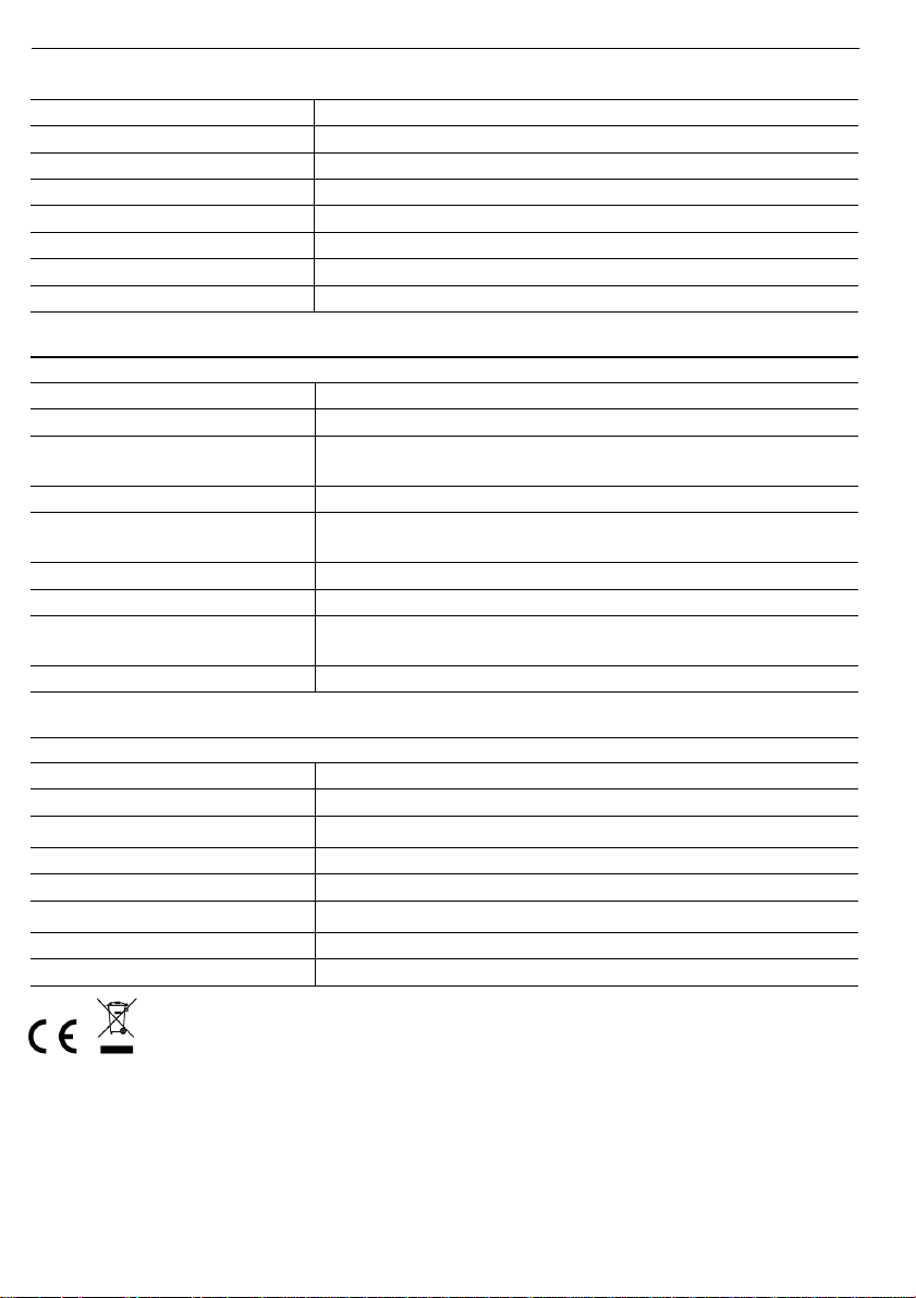
Weather index mode
UV Index, Beaufort, Wind Chill, Heat Index and Dew point
UV index range
0 ~ 16
Beaufort scale
0 ~ 12
Wind Chill range
-40 ~ 18°C, wind speed >4.8km/h
Heat index range
26 ~ 50 °C
Dew point range
-20 ~ 60°C
Display modes
Current
Memory modes
Historical Data of past 24 hours, Daily Max / Min
Dimensions (W x H x D)
392 .5 x 326 x 144 .5mm (15 .5 x 12 .8 x 5 .7in)
Weight
1096g (with batteries)
Main power
3 x AA size 1 .5V batteries
(Alkaline batteries recommended)
Auxiliary power
Solar panel
Weather data
Temperature, Humidity, Wind speed, Wind direction, Rainfall
and UV index
RF transmission range
150m
RF frequency
915Mhz (US) / 868Mhz (EU, UK) / 917Mhz (AU)
Transmission interval
• 12 seconds for wind speed and wind direction data
• 24 seconds for temperature, humidity, UV and rain data
Operating range
-40 ~ 60°C (-40 ~ 140°F) Lithium batteries required
Dimensions (W x H x D)
61 x 113 x 39 .5mm (2 .4 x 4 .4 x 1 .6in)
Weight
144g (with batteries)
Main power
2 x AA size 1 .5V batteries (alkaline recommended)
Weather data
Temperature and humidity
RF frequency
915Mhz (US) / 868Mhz (EU, UK) / 917Mhz (AU)
RF transmission range
150m
Transmission interval
60 seconds
Operating range
-40 ~ 60°C (-40 ~ 140°F) Lithium batteries required
Weather Index Display & Function Specification
Note: The following details are listed as they are displayed or operate on the console
WIRELESS 6-IN-1 WEATHER OUTDOOR SENSOR
WIRELESS HYGRO-THERMO INDOOR SENSOR
Notes on the return of batteries according to §12 BatterieVO: Batteries do not
belong in the household waste. Please dispose of all batteries as required by law,
disposal in domestic waste is expressly prohibited. Batteries and rechargeable
batteries can be dispensed free of charge at municipal collection points or in the
shops on the spot.
This manual may not be reproduced in any form without the written permission of
Page 32

32
the publisher, even in excerpts.
Telefon
E-Mail
0221 / 367 48 05
Registergericht Amtsgericht Koeln
HRA 26493
Komplementaer: HS Group
Verwaltungsgesellschaft mbH
Sitz Koeln
Registergericht Amtsgericht Koeln
HRB 64734
Geschaeftsfuehrer: Peter Haefele, Carl
Schulte
UStId DE237971721
WEEE Reg. Nr. 66110125
This manual may contain errors and misprints. However, the information in this
manual is regularly reviewed and corrections made in the next issue. We accept
no liability for technical errors or printing errors, and their consequences.
All trademarks and copyrights are acknowledged.
www.froggit.de
HS Group GmbH & Co. KG
Escherstr.31
50733 Koeln
Germany
declaration of conformity
Hereby we declare, HS-Group GmbH & Co.KG, Escherstr. 31, 50733 D-Cologne,
that this product is in compliance with the essential requirements and other
relevant provisions of Directive 1999/5 / EC.
Page 33

33
The declaration of conformity for this product can be found at: www.froggit.de or
on reques.
Page 34

34
 Loading...