

FRIULAIR AMD 3-168 Users Maintenance And Spare Parts Manual

7425MUM073_EN_2008-05
AMD 3
AMD 3AMD 3
AMD 3-
--
-168
168168
168
REFRIGERATING AIR DRYER
EN
ENEN
EN
USER’S MAINTENANCE AND SPARE PARTS MANUAL
USER’S MAINTENANCE AND SPARE PARTS MANUALUSER’S MAINTENANCE AND SPARE PARTS MANUAL
USER’S MAINTENANCE AND SPARE PARTS MANUAL
----EN
ENEN
EN---- AMD 3
AMD 3AMD 3
AMD 3----168
168168
168
Dear Customer,
thank you for choosing our product. In order to get the best performances out of this product, please read
this manual carefully.
To avoid incorrect operation of the equipment and possible physical risk to the operator, please read and
strictly follow the instructions contained in this manual.
Note, these instructions are in addition to the safety rules that apply in the country where the dryer is
installed. Before packing for shipment each AMD series refrigerated air dryer undergoes a rigorous test to
ensure the absence of any manufacturing faults and to demonstrate that the device can perform all the
functions for which it has been designed.
Once the dryer has been properly installed according to the instructions in this manual, it will be ready for
use without any further adjustment. The operation is fully automatic, and the maintenance is limited to few
controls and some cleaning operations, as detailed in the following chapters.
This manual must be maintained available in any moment for future references and it has to be
intended as inherent part of the relevant dryer.
Due to the continuous technical evolution, we reserve the right to introduce any necessary change without
giving previous notice.
Should you experience any trouble, or for further information, please do not hesitate to contact us.
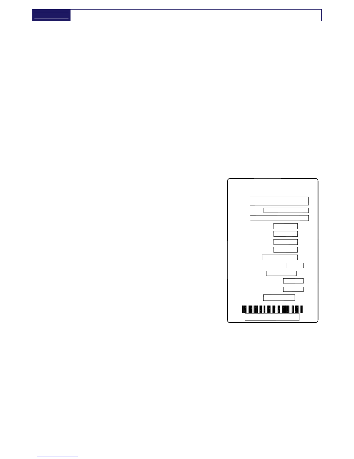
DATA NAMEPLATE
Model
Serial No.
Code
Nominal Flow Rate
Max Air Pressure
Max Inlet Air Temp.
Ambient Temp.
Refrigerant (Type and qty)
Refrig. Design Pres. HP/LP
Electric Supply
Electric Nominal Power
Fuse Max.
Manufactured
The data nameplate is located
on the back of the dryer and
shows all the primary data of the
machine. Upon installation, fill in
the table on the previous page
with all the data shown on the
data nameplate. This data
should always be referred to
when calling the manufacturer
or distributor.
The removal or alteration of the
data nameplate will void the
warranty rights.
T
A
D
0
0
0
6
Refrig. Design Pres.
HP/LP
Max Inlet Air Temp.
Electric Supply
Manufactured
Fuse Max.
Electric Nominal Power
Refrigerant
Ambient Temp.
Nominal Flow Rate
Max Air Pressure
Code
Serial No.
Model
°C
ph/V/Hz
A
W/A
type/kg
barg
°C
Nl/min
barg
WARRANTY CONDITIONS
For 12 months from the installation date, but no longer than 14 months from the delivery date, the warranty
covers eventual faulty parts, which will be repaired or replaced free of charge, except the travel, hotel and
restaurant expenses of our engineer.
The warranty doesn’t cover any responsibility for direct or indirect damages to persons, animals or
equipment caused by improper usage or maintenance, and it’s limited to manufacturing faults only.
The right to warranty repairs is subordinated to the strict compliance with the installation, use and
maintenance instructions contained in this manual.
The warranty will be immediately voided in case of even small changes or alterations to the dryer. To
require repairs during the warranty period, the data reported on the identification plate must be notified.

AMD 3
AMD 3AMD 3
AMD 3----168
168168
168
----EN
ENEN
EN----
1. SAFETY RULES
1.1. Definition of the Conventional Signs Used in This Manual
1.2. Warnings
1.3. Proper use of the dryer
1.4. Instructions for the use of pressure equipment according to ped directive 97/23/ec
2. INSTALLATION
2.1. Transport
2.2. Storange
2.3. Installation site
2.4. Installation layout
2.5. Correction factors
2.6. Connection to the compressed air system
2.7. Electrical connections
2.8. Condensate drain
3. START UP
3.1. Preliminary operation
3.2. First start-up
3.3. Start-up and shut down
4. TECHNICAL SPECIFICATIONS
4.1. Technical specifications AMD 3-25 / 230V / 50-60 Hz
4.2. Technical specifications AMD 32-168 / 230V / 50Hz
4.3. Technical specifications AMD 32E-168E / 230V / 60 Hz
4.4. Technical specifications AMD 3P-25P / 115V / 60 Hz
4.5. Caratteristiche tecniche AMD 32P-75P / 115V / 60 Hz
5. DESCRIZIONE TECNICA
5.1. Control panel
5.2. Operation
5.3. Flow diagram
5.4. Refrigerating compressor
5.5. Condenser
5.6. Filter drier
5.7. Capillary tube
5.8. Alu-dry module
5.9. Hot gas by-pass valve
5.10. Refrigerant pressure switches Pa- Pb- Pv
5.11. Safety thermo-switc T
S
5.12. DMC15 Electronic instrument (Air Dryer Controller)
5.13. Electronic level drain
6. MAINTENANCE, TROUBLESHOOTING, SPARES AND DISMANTLING
6.1. Controls and maintenance
6.2. Troubleshooting
6.3. Spare parts
6.4. Maintenance operation on the refrigerating circuit
6.5. Dismantling of the dryer
7. LIST OF ATTACHMENTS
7.1. Dryers dimensions
7.2. Exploded view
7.3. Electic diagrams
----EN
ENEN
EN---- AMD 3
AMD 3AMD 3
AMD 3----168
168168
168
1. SAFETY RULES
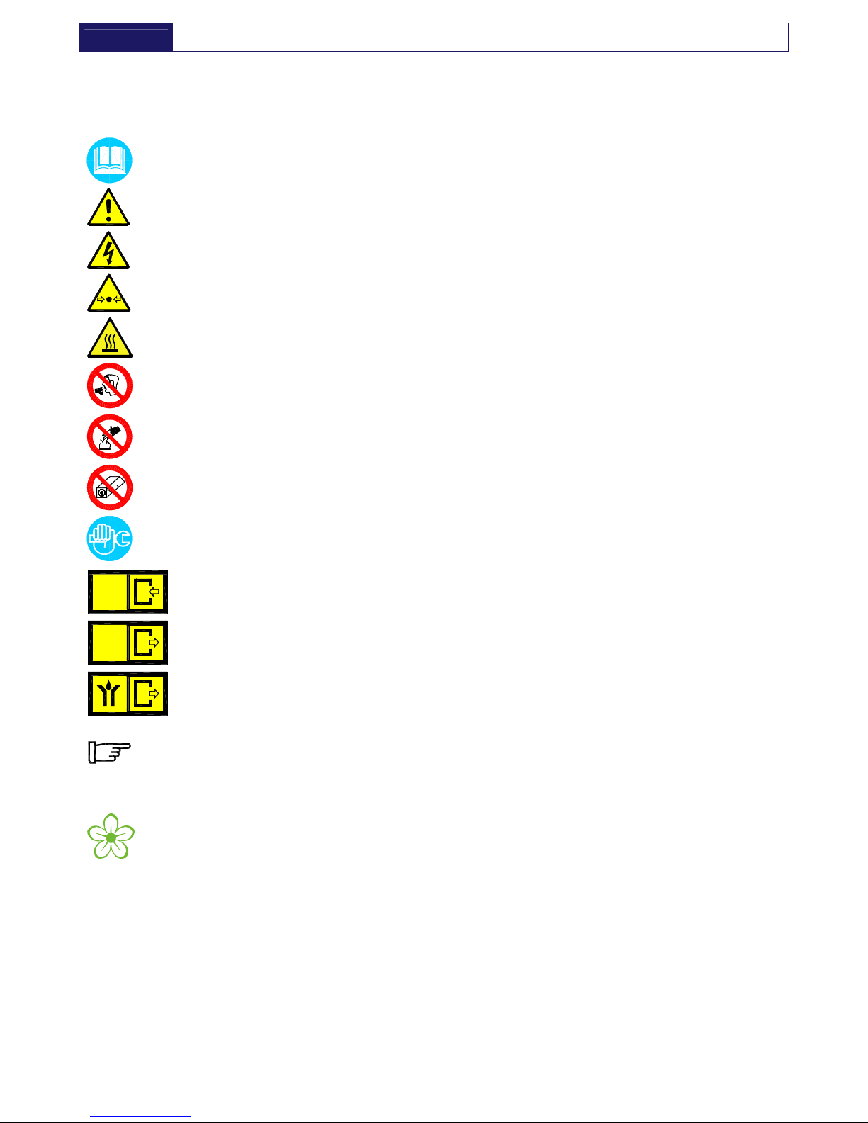
1.1. DEFINITION OF THE CONVENTIONAL SIGNS USED IN THIS MANUAL
Carefully read instruction manual before attempting any service or maintenance procedures on the
dryer.
Caution warning sign. Risk of danger or possibility of damage to equipment, if related text is not
followed properly.
Electrical hazard. Warning message indicates practices or procedures that could result in personal
injury or fatality if not followed correctly.
Danger hazard. Part or system under pressure.
Danger hazard. High temperature conditions exist during operation of system. Avoid contact until
system or component has dissipated heat.
Danger hazard. Treated air is not suitable for breathing purposes; serious injury or fatality may
result if precautions are not followed.
Danger hazard: In case of fire, use an approved fire extinguisher, water is not an acceptable
means in cases of fire.
Danger hazard. Do not operate equipment with panels removed.
Maintenance or control operation to be performed by qualified personnel only 1.
ARIA
AIR
LUFT
AIR
Compressed air inlet connection point.
ARIA
AIR
LUFT
AIR
Compressed air outlet connection point.
Condensate drain connection point.
Operations which can be worked out by the operator of the machine, if qualified 1.
NOTE : Text to be taken into account, but not involving safety precautions.
In designing this unit a lot of care has been devoted to environmental protection:
• CFC free refrigerants
• CFC free insulation parts
• Energy saving design
• Limited acoustic emission
• Dryer and relevant packaging composed of recyclable materials
This symbol requests that the user heed environmental considerations and abide with suggestions
annotated with this symbol.
1 Experienced and trained personnel acquainted with the relevant rules and laws, capable to perform the needed activities and to identify and
avoid possible dangerous situations while handling, installing, using and servicing the machine.

AMD 3
AMD 3AMD 3
AMD 3----168
168168
168
----EN
ENEN
EN----
1.2. WARNINGS
Compressed air is a highly hazardous energy source.
Never work on the dryer with pressure in the system.
Never point the compressed air or the condensate drain outlet hoses towards anybody.
The user is responsible for the proper installation of the dryer. Failure to follow instructions given in
the “Installation” chapter will void the warranty. Improper installation can create dangerous situations
for personnel and/or damages to the machine could occur.
Only qualified personnel are authorized to service electrically powered devices. Before attempting
maintenance, the following conditions must be satisfied :
• Ensure that main power is off, machine is locked out, tagged for service and power cannot be
restored during service operations.
• Ensure that valves are shut and the air circuit is at atmospheric pressure. De-pressurize the dryer.
These refrigerating air dryers contain R134a or R404A HFC type refrigerant fluid. Refer to the
specific paragraph - maintenance operation on the refrigerating circuit.
Warranty does not apply to any unit damaged by accident, modification, misuse, negligence or
misapplication. Unauthorized alterations will immediately void the warranty.
In case of fire, use an approved fire extinguisher, water is not an acceptable means in cases of
electrical fire.
1.3. PROPER USE OF THE DRYER
This dryer has been designed, manufactured and tested for the purpose of separating the humidity normally
contained in compressed air. Any other use has to be considered improper.
The Manufacturer will not be responsible for any problem arising from improper use; the user will bear
responsibility for any resulting damage.
Moreover, the correct use requires the adherence to the installation instructions, specifically:
• Voltage and frequency of the mains.
• Pressure, temperature and flow-rate of the incoming air.
• Ambient temperature.
This dryer is supplied tested and fully assembled. The only operation left to the user is the connection to the
plant in compliance with the instructions given in the following chapters.
The purpose of the machine is the separation of water and eventual oil particles present in
compressed air. The dried air cannot be used for breathing purposes or for operations leading to
direct contact with foodstuff.
This dryer is not suitable for the treatment of dirty air or of air containing solid particles.
----EN
ENEN
EN---- AMD 3
AMD 3AMD 3
AMD 3----168
168168
168
1.4. INSTRUCTIONS FOR THE USE OF PRESSURE EQUIPMENT ACCORDING TO PED
DIRECTIVE 97/23/EC
To ensure the safe operation of pressure equipments, the user must conform strictly to the above directive
and the following :
1. The equipment must only be operated within the temperature and pressure limits stated on the
manufacturer’s data nameplate.
2. Welding on heat-exchanger is not recommended.
3. The equipment must not be stored in badly ventilated spaces, near a heat source or inflammable
substances;
4. Vibration must be eliminated from the equipment to prevent fatigue failure.
5. Automatic condensate drains should be checked for operation every day to prevent a build up of
condensate in the pressure equipment.
6. The maximum working pressure stated on the manufacturer’s data nameplate must not be exceeded.
Prior to use, the user must fit safety / pressure relief devices.
7. All documentation supplied with the equipment (manual, declaration of conformity etc.) must be kept
for future reference.
8. Do not apply weights or external loads on the vessel or its connecting piping.
TAMPERING, MODIFICATION AND IMPROPER USE OF THE PRESSURE EQUIPMENT ARE
FORBIDDEN. Users of the equipment must comply with all local and national pressure
equipment legislation in the country of installation.
2. INSTALLATION
2.1. TRANSPORT
Check for visible loss or damage, if no visible damage is found place the unit near to the installation point
and unpack the contents.
• Always keep the dryer in the upright vertical position. Damage to compo
nents could result if unit is laid on
its side or if placed upside down.
• Store machine in a clean, dry environment, do not expose to severe weather environments.
• Handle with care. Heavy blows could cause irreparable damage.
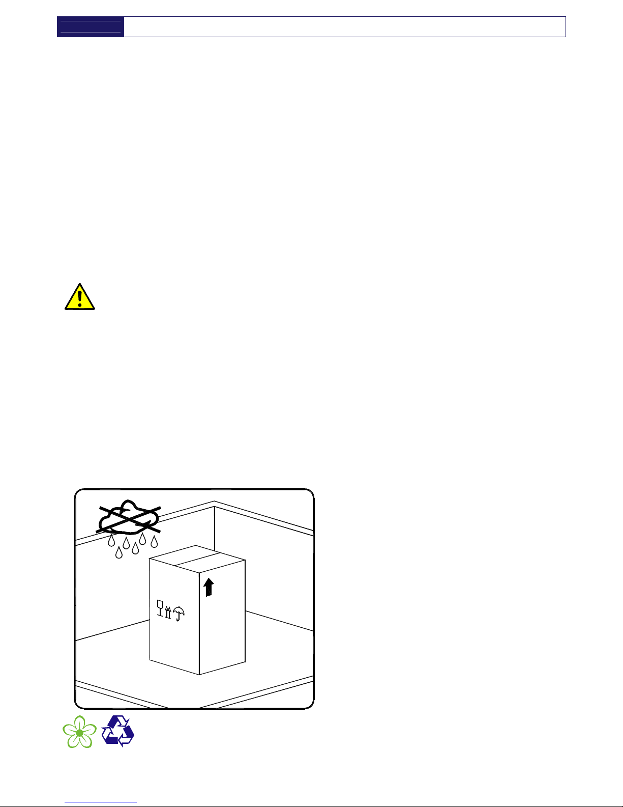
2.2. STORANGE
S
C
C
0
0
0
1
Even when packaged, keep the machine
protected from severity of the weather.
Keep the dryer in vertical position, also when
stored. Turning it upside down some parts could
be irreparably damaged.
If not in use, the dryer can be stored in its
packaging in a dust free and protected site at a
maximum temperature of 50 °C, and a specific
humidity not exceeding 90%. Should the
stocking time exceed 12 months, please contact
the manufacturer.
The packaging materials are recyclable. Dispose of material in compliance with the rules
and regulations in force in the destination country.
AMD 3
AMD 3AMD 3
AMD 3----168
168168
168
----EN
ENEN
EN----
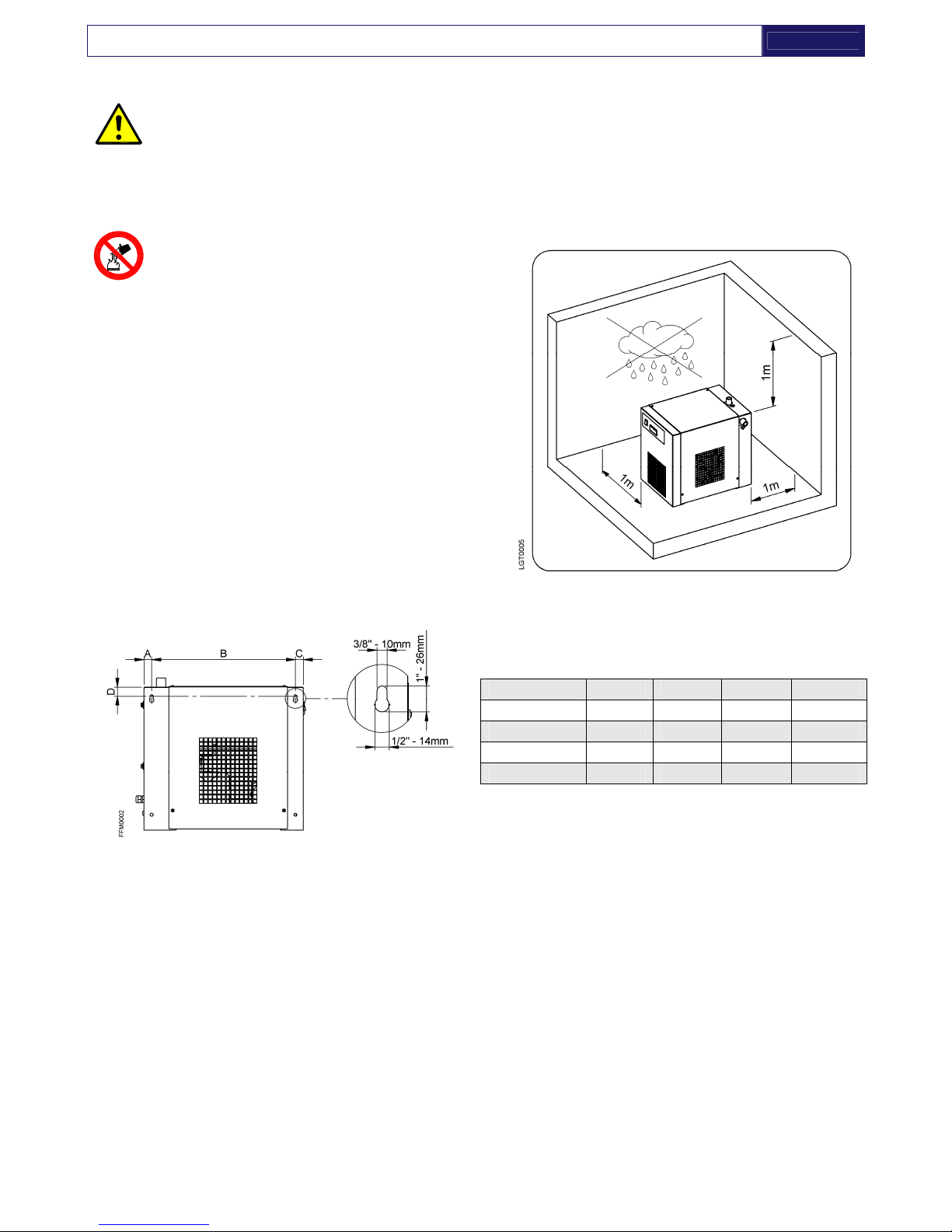
2.3. INSTALLATION SITE
Failure to install dryer in the proper ambient conditions will affect the dryer’s ability to condense
refrigerant gas. This can cause higher loads on the compressor, loss of dryer efficiency and
performance, overheated condenser fan motors, electrical component failure and dryer failure due
to the following: compressor loss, fan motor failure and electrical component failure. Failures of
this type will affect warranty considerations.
Do not install dryer in an environment of corrosive chemicals, explosive gasses, poisonous
gasses; steam heat, areas of high ambient conditions or extreme dust and dirt.
Don’t use water to extinguish fire on the dryer
on in the surrounding area.
Minimal installation requirements :
• Select a clean room dry, free from dust, and protected
from atmospheric disturbances.
• The supporting area must be smooth, horizontal and
able to hold the weight of the dryer.
• Minimum ambient temperature +1 °C.
• Maximum ambient temperature +45°C.
• Leave at least 1 meter of free space on every side of
the drier for ventilation purposes and maintenance
operations.
The dryer doesn't require to be fixed to the supporting
surface. The dryer needs to be fixed to the supporting
s
urface only with particular installation procedures
(dryer on brakets, hanging units, etc.)
Dryer hanging (AMD 3-32 only):
Dryer A [mm] B [mm] C [mm] D [mm]
AMD 3 20 305 20 30
AMD 6-18 25 465 25 30
AMD 25 40 360 20 30
AMD 32 40 385 20 30
----EN
ENEN
EN---- AMD 3
AMD 3AMD 3
AMD 3----168
168168
168
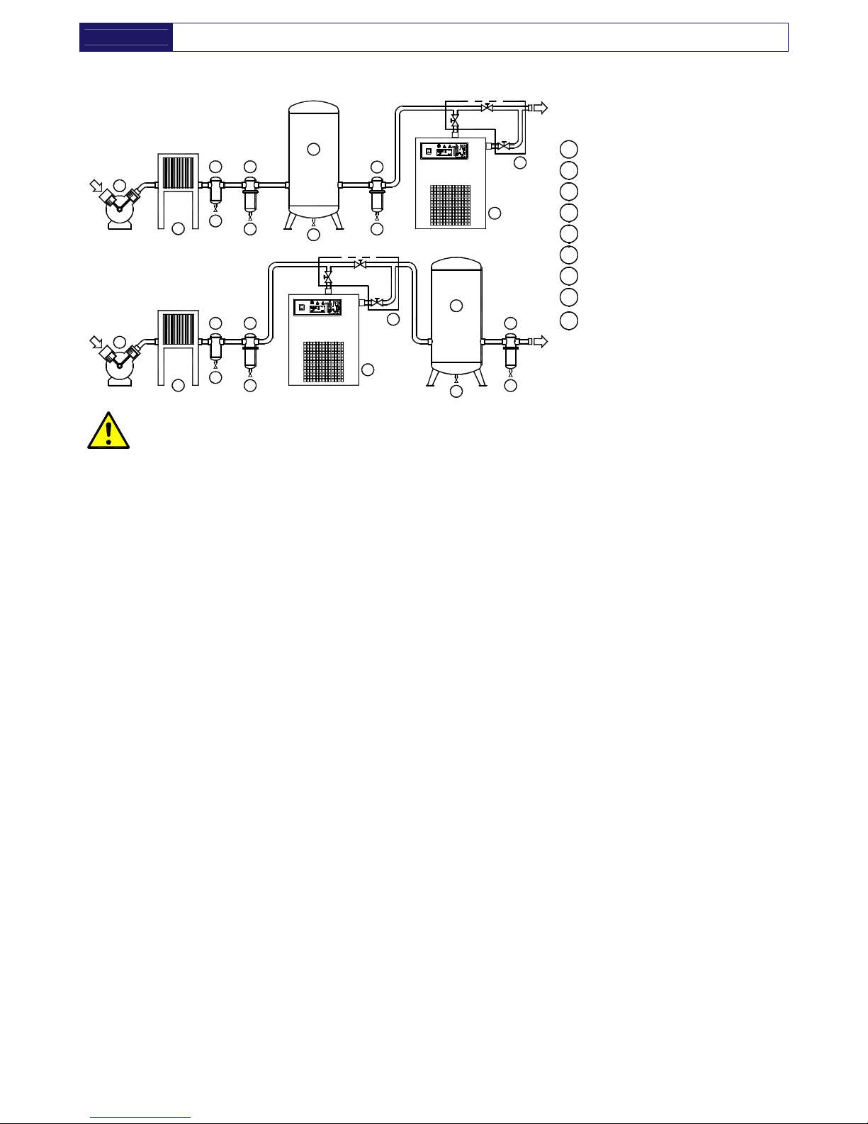
2.4. INSTALLATION LAYOUT
1
Air compressor
2
Final refrigerator
3
Condensate separator
4
Pre-Filter (min. 5 micron)
5
By-pass group
6
Dryer
7
Compressed air tank
8
Final filter
9
Condensate drain
9 9
2
9
- A -
- B -
1
3
9
1
2
9
3
4
IN
5
6
OUT
9
9
4
7
9
8
8
7
6
IN
OUT
5
D
G
T
0
0
0
2
In case of heavily polluted inlet air (ISO 8573.1 class 3.-.3 or worse quality), we recommend
the additional installation of a pre-filter (5 micron minimum) to prevent a clogging of the
heat exchanger.
Type A installation is suggested when the compressor operates at reduced intermittence and the total
consumption equals the compressor flow rate.
Type B installation is suggested when the air consumption can consistently change with peak values highly
exceeding the flow rate of the compressors. The capacity of the tank must be sized in order to compensate
eventual instantaneous demanding conditions (peak air consumption).
AMD 3
AMD 3AMD 3
AMD 3----168
168168
168
----EN
ENEN
EN----
2.5. CORRECTION FACTORS
Correction factor for operating pressure changes :
Inlet air pressure barg 4 5 6 7 8 10 12 14 15 16
Factor (F1) 0.77 0.86 0.93 1.00 1.05 1.14 1.21 1.27 1.30 1.33
Correction factor for ambient temperature changes (Air-Cooled):
Ambient temperature ºC 25 30 35 40 45
Factor (F2) 1.00 0.98 0.95 0.88 0.80
Correction factor for inlet air temperature changes:
Air temperature
ºC
30 35 40 45 50 55
Factor (F3) 1.15 1.00 0.84 0.71 0.59 0.50
Correction factor for DewPoint changes:
DewPoint ºC 3 5 7 10
Factor (F4) 0.91 1.00 1.10 1.26
How to find the air flow capacity:
Air flow capacity = Nominal duty x Factor (F1) x Factor (F2) x Factor (F3) x Factor (F4)
Example:
An AMD 18 has a nominal duty of 1800 l/min . What is the maximum allowable flow through the dryer under
the following operating conditions:
–
Inlet air pressure = 7 barg
–
Ambient temperature = 35°C
–
Inlet air temperature = 40°C
–
Pressure DewPoint = 3°C
–
Factor (F1) = 1.00
–
Factor (F2) = 0.95
–
Factor (F3) = 0.84
–
Factor (F4) = 0.91
Each item of data has a corresponding numerical factor which multiplied by the design air flow is as follows:
Air flow capacity = 108 x 1.00 x 0.95 x 0.84 x 0.91 = 1307 l/mi n
1307 l/min This is the maximum flow rate that the dryer can accept under these operating conditions.
How to select a suitable dryer for a given duty:
Design air flow
Minimum std. air flow rate =
Factor (F1) x Factor (F2) x Factor (F3) x Factor (F4)
Example:
With the following operating parameters:
–
Design air flow = 1100 l/m in
–
Inlet air pressure = 7 barg
–
Ambient temperature = 35°C
–
Inlet air temperature = 40°C
–
Pressure DewPoint = 3°C
–
Factor (F1) = 1.00
–
Factor (F2) = 0.95
–
Factor (F3) = 0.84
–
Factor (F4) = 0.91
In order to select the correct dryer model the required flow rate is to be divided by the correction factors relating
to above mentioned parameters:
1100
Minimum std. air flow rate =
1.00 x 0.95 x 0.84 x 0.91
= 1515 l/ min
Therefore the model suitable for the conditions above is AMD 18 (1800 l/ min - nominal duty).
----EN
ENEN
EN---- AMD 3
AMD 3AMD 3
AMD 3----168
168168
168
2.6. CONNECTION TO THE COMPRESSED AIR SYSTEM
Operations to be performed by qualified personnel. Never operate with plants under pressure.
The user is responsible to ensure that the dryer will never be operated with pressure exceeding
the nominal values.
Eventual over-pressure could be dangerous both for the operator and the machine.
The temperature and the amount of air entering the dryer must comply with the limits reported on the data
plate. In case of treatment of air at particularly high temperatures, the installation of a final refrigerator could
result necessary. The cross section of the connecting piping, which must be free from dust, rust, chips and
other impurities, must be consistent with the flow-rate of the dryer.
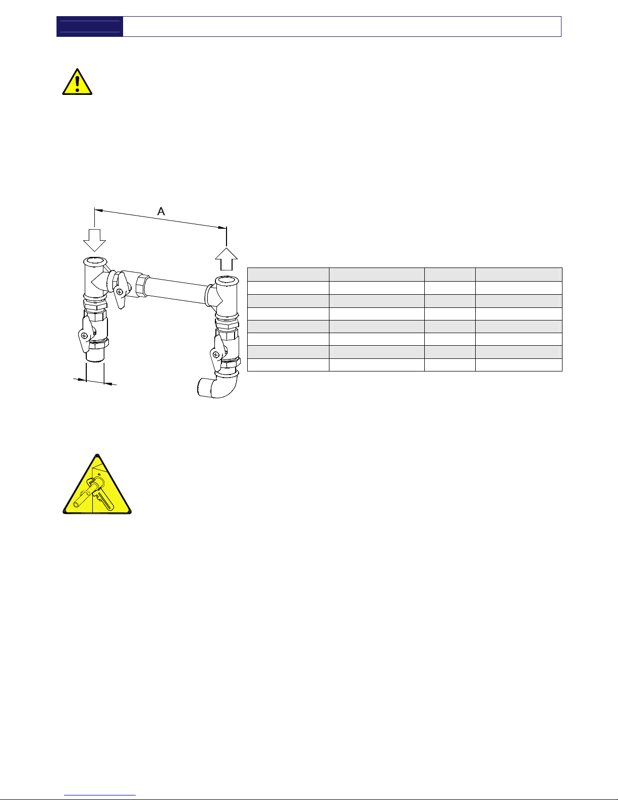
In order to facilitate the maintenance operations, a by-pass group has been installed, as shown in the
following illustration.
Dryer Ø [BSP-F] A [mm] By-Pass Code
AMD 3 G 3/8” BSP-F
40 2240GBP019
AMD 6-18 G 1/2” BSP-F
210 2240GBP021
AMD 25 G 1” BSP-F 205 2240GBP022
AMD 32-52 G 1.1/4” BSP-F
205 2240GBP023
AMD 61-75 G 1.1/2” BSP-F
235 2240GBP024
AMD 105-130 G 2” BSP-F
345 2240GBP025
AMD 168 G 2.1/2” BSP-F
410 2240GBP026
Ø
B
P
Y
0
0
0
1
In realising the dryer, particular measures have been taken in order to limit the vibration which could occur
during the operation. Therefore we recommend to use connecting pipes able to insulate the dryer from
possible vibrations originating from the line (flexible hoses, vibration damping fittings, etc.).
CAUTION:
PIPING THE DRYER, INLET/OUTLET CONNECTIONS MUST BE SUPPORTED AS
SHOW IN THE DIAGRAM.
FAILING WILL RESULT IN DAMAGE

AMD 3
AMD 3AMD 3
AMD 3----168
168168
168
----EN
ENEN
EN----
2.7. ELECTRICAL CONNECTIONS
Qualified personnel should carry out connecting unit to the main power. Be sure to check the local
codes in your area.
Before connecting the unit to the electrical supply, verify the data nameplate for the proper electrical
information. Voltage tolerance is +/- 5%.
AMD 3-75 dryers are supplied with a standard VDE 16A - Shucko power cord and plug assembly (two
poles and a ground). AMD 105-168 dryers are supplied with a junction box.
Be sure to provide the proper fuses or breakers based on the data tag information located on the back of
the unit. The main power receptacle must be protected with a thermal overload/differential relay
(I∆n=0.03A), rated to the power consumption of the dryer (refer to data nameplate for nominal values). The
power supply cord must meet or exceed ratings for the total amp draw of the unit.
Connect to a properly grounded outlet. Improper connection of the equipment-grounding
conductor can result in risk of electric shock.
Do not use adapters on the plug receptacle - if it does not fit the outlet, have a proper outlet
installed by a qualified electrician.
2.8. CONDENSATE DRAIN
The condensate is discharge at the system pressure.
Drain line should be secured
Never point the condensate drain line towards anybody.
The dryer comes with a flexible plastic drain tube.
The condensate drain occurs through a solenoid valve protected with a mechanical strainer.
The condensate coming from the separator is previously filtered, then discharged.
The solenoid valve coil is operated by electronic instrument (dryer controller).
If an electronic drainer is installed, the intervention times are determined by the internal capacitive sensor
(see specific paragraph).
The drainers cannot be connected to pressurized systems.
Don’t dispose the condensate in the environment.
The condensate collected in the dryer contains oil particles released in the air by the compressor.
Dispose the condensate in compliance with the local rules.
We suggest to install a water-oil separator where to convey all the condensate drain coming from
compressors, dryers, tanks, filters, etc.
3. START UP
3.1. PRELIMINARY OPERATION
Verify that the operating parameters match with the nominal values reported on the data plate of the
dryer (voltage, frequency, air pressure, air temperature, ambient temperature, etc.).
Before delivery, each dryer is submitted to accurate tests simulating real operating conditions.
Nevertheless, the unit could be damaged during transportation. We therefore suggest to check the integrity
of the dryer upon arrival and to keep it under control during the first hours of operation.
The start-up must be performed by qualified personnel.
It’s mandatory that the engineer in charge adopt safety operational conditions complying with the
local safety and accident prevention requirements.
The same engineer will be responsible for the proper and safe operation of the dryer.
Never operate the dryer if the panels are not in place.

----EN
ENEN
EN---- AMD 3
AMD 3AMD 3
AMD 3----168
168168
168
3.2. FIRST START-UP
This procedure should be followed on first start-up, after periods of extended shutdown or
following maintenance procedures.
Qualified personnel must perform the start-up.
Sequence of operations (refer to paragraph 5.1 Control Panel) :
• Ensure that all the steps of the “Installation” chapter have been observed.
• Ensure that the connection to the compressed air system is correct and that the piping is suitably fixed
and supported.
• Ensure that the condensate drain pipe is properly fastened and connected to a collection system or
container.
• Ensure that the by-pass system (if installed) is open and the dryer is isolated
• Ensure that the manual valve of the condensate drain circuit is open.
• Remove any packaging and other material which could obstruct the area around the dryer.
• Activate the mains switch.
• Turn on the main switch - pos. 1 on the control panel.
• Ensure that the DMC15 electronic instrument is ON.
• Ensure the consumption matches with the values of the data plate.
• Ensure the fan work properly - wait for its first interventions.
• Allow the dryer temperature to stabilise at the pre-set value.
• Slowly open the air inlet valve.
• Slowly open the air outlet valve.
• Slowly close the central by-pass valve of the system (if installed).
• Check the piping for air leakage.
• Ensure the drain is regularly cycling - wait for its first interventions.
3.3. START-UP AND SHUT DOWN
Start-up (refer to paragraph 5.1 Control Panel) :
• Check the condenser for cleanliness.
• Verify that the system is powered.
• Turn on the main switch - pos. 1 on the control panel.
• Ensure that DMC15 electronic instrument is ON.
• Wait a few minutes; verify that the DewPoint temperature displayed on DMC15 electronic instrument is
correct and that the condensate is regularly drained.
• Switch on the air compressor.
Shut down (refer to paragraph 5.1 Control Panel) :
• Verify that the DewPoint temperature displayed on DMC15 electronic instrument is correct.
• Switch OFF the air compressor.
• After a few minutes, switch off the main switch on the control panel of the dryer (pos. 1).
NOTE : A DewPoint included in the green operating area of the electronic controller is correct
according to the possible working conditions (flow-rate, temperature of the incoming air, ambient
temperature, etc.)
During the operation, the refrigerating compressor will run continuously. The dryer must remain on during
the full usage period of the compressed air, even if the air compressor works intermittently.
The number of starts must be no more than 6 per hour. The dryer must stop running for at
least 5 minutes before being started up again.
The user is responsible for compliance with these rules. Frequent starts may cause
irreparable damage.

AMD 3
AMD 3AMD 3
AMD 3----168
168168
168
----EN
ENEN
EN----
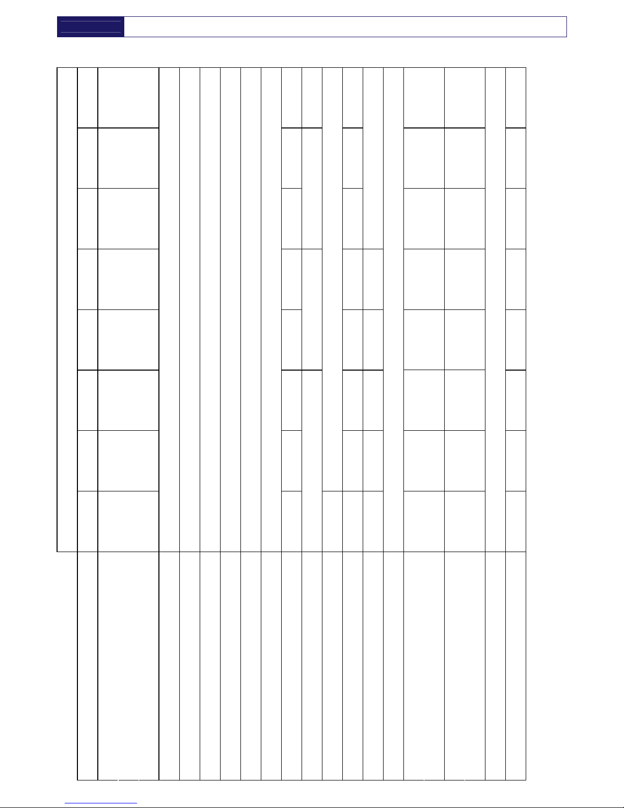
4. TECHNICAL SPECIFICATIONS
4.1. TECHNICAL SPECIFICATIONS AMD 3-25 / 230V / 50-60 HZ
25
2500
150
88
14
0.24
G 1”
0.33
390 (460)
2.4 (2.5)
610 (670)
3.3 (3.4)
34
18
1800
108
64
0.32
0.30
290 (330)
1.9 (2.0)
390 (460)
2.2 (2.5)
32
12
1200
72
42
0.14
0.25
300
210 (250)
1.4 (1.5)
280 (340)
1.7 (1.8)
28
9
950
57
34
0.09
0.22
190 (210)
1.3 (1.3)
270 (290)
1.5 (1.6)
26
6
600
36
21
0.04
G 1/2”
160 (190)
1.1 (1.2)
200 (250)
1.2 (1.4)
25
Air-Cooled
3
350
21
12
+5
equal to
0.85 g/m
3
di H
2
O
+25 (+45)
+1
+35 (+55)
7
16
0.15
G 3/8”
R134.a
0.20
200
1/230/50-60
150 (180)
1.1 (1.1)
170 (220)
1.2 (1.3)
< 70
21
[l/min]
[m
3
/h]
[scfm]
[°C]
[°C]
[°C]
[°C]
[barg]
[barg]
[bar]
[BSP-F]
[kg]
[m
3
/h]
[Ph/V/Hz]
[W]
[A]
[W]
[A]
[dbA]
[kg]
AMD MODEL
Air flow rate at nominal condition
1
Pressure DewPoint at nominal condition
1
Nominal ambient temperature (max.)
Min. ambient temperature
Nominal inlet air temperature (max.)
Nominal inlet air pressure
Max. inlet air pressure
Air pressure drop - p
Inlet - Outlet connections
Refrigerant type
Refrigerant quantity
2
Cooling air flow
Standard Power Supply
2
Nominal electric absorption 50Hz (60Hz)
Max. electric absorption 50Hz (60Hz)
Max. level noise at 1 m
Weight
1
The nominal condition refers to an ambient temperature of +25°C with inlet air at 7 barg and +35 °C.
2
Check the data shown on the identification plate.
----EN
ENEN
EN---- AMD 3
AMD 3AMD 3
AMD 3----168
168168
168
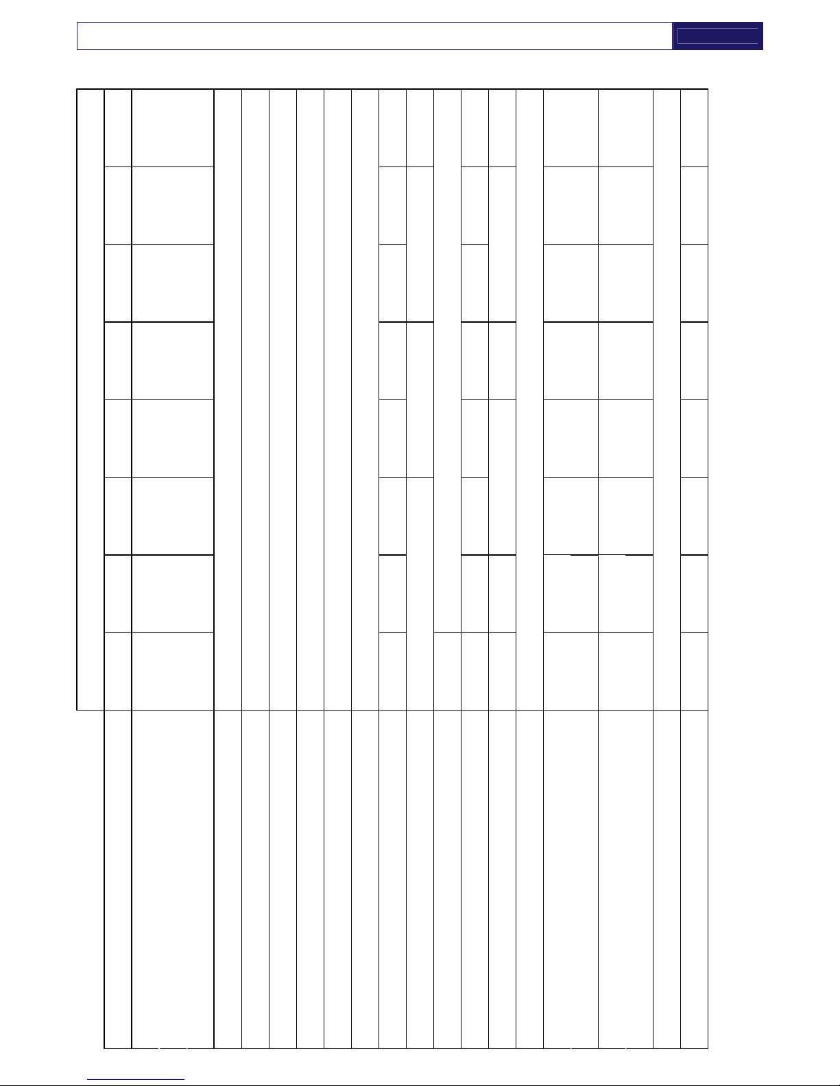
4.2. TECHNICAL SPECIFICATIONS AMD 32-168 / 230V / 50HZ
168
16800
1008
594
0.15
G 2.1/2”
1.90
1590
7.5
2350
11.3
144
130
13000
780
459
0.20
1.30
1550
7.4
2100
9.8
96
105
10500
630
371
0.14
G 2”
1.10
1900
940
4.3
1350
6.3
94
75
7500
450
265
0.25
0.70
450
740
3.6
1050
4.8
56
61
6100
366
216
0.19
G 1.1/2”
0.57
400
950
4.7
1400
6.8
54
52
5200
312
184
0.34
0.42
600
930
4.6
1350
6.6
41
43
4300
258
152
0.24
R404A
0.40
380
750
3.3
1150
5.4
40
Air-Cooled
32
3200
192
113
+5
equal to
0.85 g/m
3
di H
2
O
+25 (+45)
+1
+35 (+55)
7
14
0.16
G 1.1/4”
R134.a
0.44
350
1/230/50
480
2.9
700
3.8
< 70
39
[l/min]
[m
3
/h]
[scfm]
[°C]
[°C]
[°C]
[°C]
[barg]
[barg]
[bar]
[BSP-F]
[kg]
[m
3
/h]
[Ph/V/Hz
]
[W]
[A]
[W]
[A]
[dbA]
[kg]
AMD MODEL
Air flow rate at nominal condition
1
Pressure DewPoint at nominal condition
1
Nominal ambient temperature (max.)
Min. ambient temperature
Nominal inlet air temperature (max.)
Nominal inlet air pressure
Max. inlet air pressure
Air pressure drop - p
Inlet - Outlet connections
Refrigerant type
Refrigerant quantity
2
Cooling air flow
Standard Power Supply
2
Nominal electric absorption
Max. electric absorption
Max. level noise at 1 m
Weight
1
The nominal condition refers to an ambient temperature of +25°C with inlet air at 7 barg and +35 °C.
2
Check the data shown on the identification plate.
AMD 3
AMD 3AMD 3
AMD 3----168
168168
168
----EN
ENEN
EN----
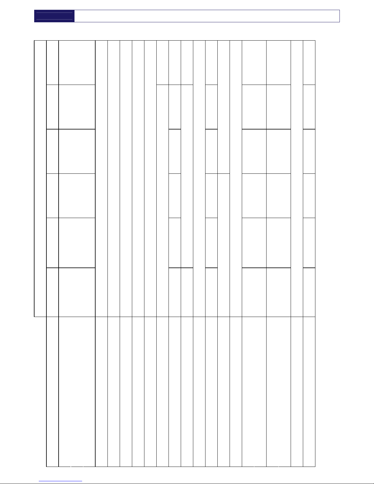
4.3. TECHNICAL SPECIFICATIONS AMD 32E-168E / 230V / 60 HZ
168E
16800
1008
594
0.15
G 2.1/2”
2.10
2600
2250
10.3
2950
14.5
144
130E
13000
780
459
0.20
1.40
2070
9.6
2890
13.2
96
105E
10500
630
371
0.14
G 2”
1.20
2400
1150
5.1
1550
7.2
94
75E
7500
450
265
0.25
0.85
900
910
4.1
1260
5.7
56
61E
6100
366
216
0.19
G 1.1/2”
0.68
1050
4.6
1460
6.6
54
52E
5200
312
184
0.34
0.47
600
1000
4.5
1400
6.2
45
43E
4300
258
152
0.24
R404A
0.45
380
970
4.4
1350
5.9
42
Air-Cooled
32E
3200
192
113
+5
equal to
0.85 g/m
3
di H
2
O
+25 (+45)
+1
+35 (+55)
7
14
0.16
G 1.1/4”
R134.a
0.44
350
1/230/60
630
3.8
720
4.3
< 70
39
[l/min]
[m
3
/h]
[scfm]
[°C]
[°C]
[°C]
[°C]
[barg]
[barg]
[bar]
[BSP-F]
[kg]
[m
3
/h]
[Ph/V/Hz]
[W]
[A]
[W]
[A]
[dbA]
[kg]
AMD MODEL
Air flow rate at nominal condition
1
Pressure DewPoint at nominal condition
1
Nominal ambient temperature (max.)
Min. ambient temperature
Nominal inlet air temperature (max.)
Nominal inlet air pressure
Max. inlet air pressure
Air pressure drop - p
Inlet - Outlet connections
Refrigerant type
Refrigerant quantity
2
Cooling air flow
Standard Power Supply
2
Nominal electric absorption
Max. electric absorption
Max. level noise at 1 m
Weight
1
The nominal condition refers to an ambient temperature of +25°C with inlet air at 7 barg and +35 °C.
2
Check the data shown on the identification plate.
----EN
ENEN
EN---- AMD 3
AMD 3AMD 3
AMD 3----168
168168
168
4.4. TECHNICAL SPECIFICATIONS AMD 3P-25P / 115V / 60 HZ
25P
2500
150
88
14
0.24
G 1”
0.33
490
5.1
650
6.0
34
18P
1800
108
64
0.32
0.30
420
3.5
460
3.9
32
12P
1200
72
42
0.14
0.25
300
280
3.0
320
3.5
28
9P
950
57
34
0.09
0.22
220
2.6
280
3.1
26
6P
600
36
21
0.04
G 1/2”
0.21
190
2.4
240
2.8
25
Air-Cooled
3P
350
21
12
+5
equal to
0.85 g/m
3
di H
2
O
+25 (+45)
+1
+35 (+55)
7
16
0.15
G 3/8”
R134.a
0.20
200
1/115/60
180
2.2
220
2.4
< 70
21
[l/min]
[m
3
/h]
[scfm]
[°C]
[°C]
[°C]
[°C]
[barg]
[barg]
[bar]
[BSP-F]
[kg]
[m
3
/h]
[Ph/V/Hz]
[W]
[A]
[W]
[A]
[dbA]
[kg]
AMD MODEL
Air flow rate at nominal condition
1
Pressure DewPoint at nominal condition
1
Nominal ambient temperature (max.)
Min. ambient temperature
Nominal inlet air temperature (max.)
Nominal inlet air pressure
Max. inlet air pressure
Air pressure drop - p
Inlet - Outlet connections
Refrigerant type
Refrigerant quantity
2
Cooling air flow
Standard Power Supply
2
Nominal electric absorption
Max. electric absorption
Max. level noise at 1 m
Weight
1
The nominal condition refers to an ambient temperature of +25°C with inlet air at 7 barg and +35 °C.
2
Check the data shown on the identification plate.
 Loading...