

Page 1
Rotary Encoder
The rotary encoder is a rotary input device (as in knob) that provides an indication of how much the
knob has been rotated AND what direction it is rotating in. It’s a great device for stepper and servo
motor control. You could also use it to control devices like digital potentiometers.
Rotary Encoder Basics
A rotary encoder has a fixed number of positions per revolution. These positions are
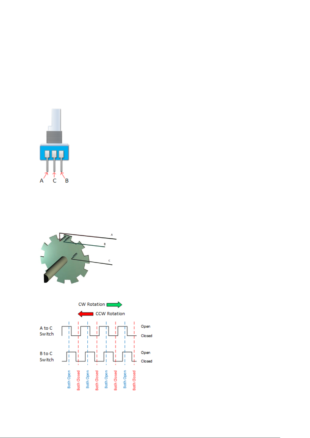
easily felt as small “clicks” you turn the encoder. On one side of the switch there are
three pins. They are normally referred to as A, B and C.
Inside the encoder there are two switches. Once switch connects pin A to pin C and
the other switch connects pin B to C. In each encoder position, both switches are
either opened or closed. Each click causes these switches to change states as
follows:
If both switches are closed, turning the encoder either clockwise or
counterclockwise one position will cause both switches to open
If both switches are open, turning the encoder either clockwise or counterclockwise one position will
cause both switches to close.
The illustration below is representative of how the switch is constructed.
As you can see, the angular position of the A terminal and the B
terminal is such that:
• Rotating the switch clockwise will cause the switch connecting
A and C to change states first.
• Rotating the switch counterclockwise will cause the switch
connecting B and C to change states first.
•
If we were to represent the opening and closing
of the switches as wave forms, it would look
something like this. Essentially, determining
which switch changed states first is how the
direction of rotation is determined.
If A changed states first, the switch is rotating in
a clockwise direction.
If B changed states first, the switch is rotating in
a counter clockwise direction.
Page 2
Pinout
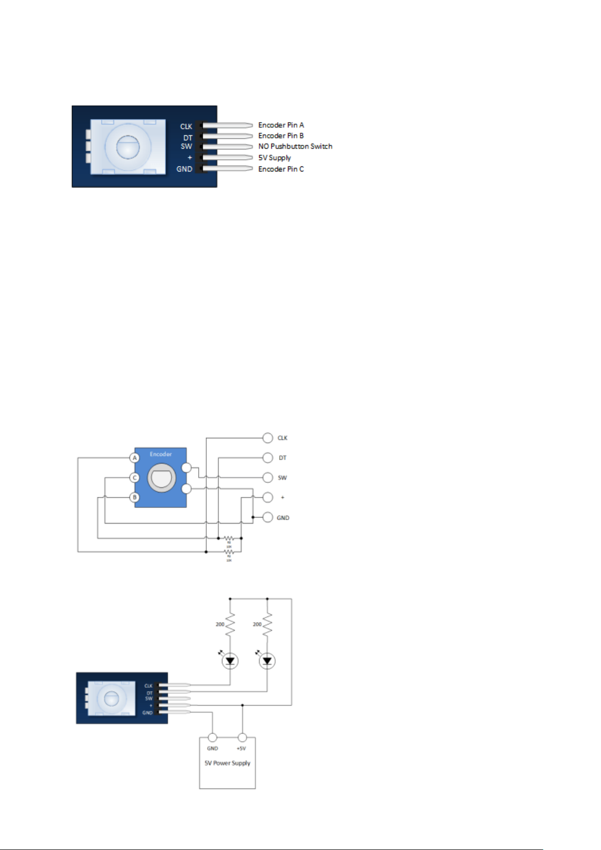
The module is designed so that a low is
output when the switches are closed
and a high when the switches are open.
The low is generated by placing a ground at Pin C and passing it to the CLK and DT pins when
switches are closed.
The high is generated with a 5V supply input and pullup resistors, such that CLK and DT are both high
when switches are open.
Not previously mentioned is the existence of push button switch that is integral to the encoder. If
you push on the shaft, a normally open switch will close. The feature is useful if you want to change
switch function. For example, you may wish to have the ability to between coarse and fine
adjustments.
Rotary Encoder Schematic
A schematic for this module is provided below.
R2 and R3 in the schematic are pull up resistors.
Successfully implementing the Rotary Encoder
into any project requires a clear understanding
of everything that has been discussed thus far. If
you’re still a little fuzzy, you may wish to throw
together the evaluation circuit illustrated below:
VERY SLOWLY rotate then encoder shaft both
clockwise and counter clockwise. Notice which
LEDs change state first with rotation.
Page 3

Module Connection to the Arduino
Pretty straight forward… All you need to do is
connect four wires to the module.
The Arduino Sketch
This is a simple sketch that shows how to count the encoder position and how to determine direction
of rotation. It has no switch de-bounce, nor does it use interrupts. A fully developed application
might need to incorporate these in order to make it robust.
int pinA = 3; // Connected to CLK
int pinB = 4; // Connected to DT
int encoderPosCount = 0;
int pinALast;
int aVal;
boolean bCW;
void setup() {
pinMode (pinA,INPUT);
pinMode (pinB,INPUT);
/* Read Pin A
Whatever state it's in will reflect the last position
*/
pinALast = digitalRead(pinA);
Serial.begin (9600);
}
void loop() {
aVal = digitalRead(pinA);
if (aVal != pinALast){ // Means the knob is rotating
// if the knob is rotating, we need to determine direction
// We do that by reading pin B.
if (digitalRead(pinB) != aVal) { // Means pin A Changed first - We're Rotating
Clockwise
encoderPosCount ++;
bCW = true;
} else {// Otherwise B changed first and we're moving CCW
bCW = false;
encoderPosCount--;
}
Serial.print ("Rotated: ");
if (bCW){
Serial.println ("clockwise");
}else{
Serial.println("counterclockwise");
}
Serial.print("Encoder Position: ");
Serial.println(encoderPosCount);
}
pinALast = aVal;
}
 Loading...