

Page 1
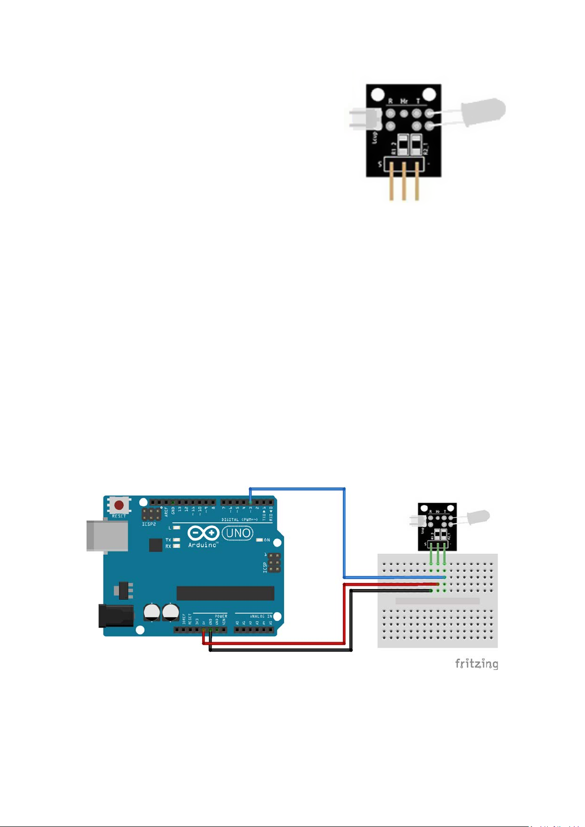
Heartbeat Sensor Module
This project uses bright infrared (IR) LED and a photo
transistor to detect the pulse of the finger, a red LED flashes
with each pulse.
Pulse monitor works as follows: The LED is the light side of
the finger, and photo transistor on the other side of the
finger, photo transistor used to obtain the flux emitted,
when the blood pressure pulse by the finger when the resistance of the photo transistor will be
slightly changed.
An important thing is to shield stray light into the phototransistor. For home lighting that is
particularly important because the lights at home mostly based 50HZ or 60HZ fluctuate, so faint
heartbeat will add considerable noise.
Additional bandpass filtering is most likely required to achieve good data.
Pinout and Connection to Arduino
Connect the Power line (middle) and ground (-) to +5 and GND respectively. Connect signal (DO) to
pin 3 on the Arduino.
Page 2

Arduino Example Sketch
The example sketch will output the raw sensor value and a filtered version in serial monitor.
int sensorPin = 0;
double alpha = 0.75;
int period = 100;
double change = 0.0;
double minval = 0.0;
void setup ()
{
Serial.begin (9600);
}
void loop ()
{
static double oldValue = 0;
static double oldChange = 0;
int rawValue = analogRead (sensorPin);
double value = alpha * oldValue + (1 - alpha) * rawValue;
Serial.print (rawValue);
Serial.print (",");
Serial.println (value);
oldValue = value;
delay (period);
}
 Loading...