

Page 1
5V Relay Module
TTL Control Signal
5VDC to 12VDC
Maximum AC
10A 250VAC
Maximum DC
10A 30VDC
Contact type
NC and NO
Dimensions
27mm x 34mm [1.063in x 1.338in]
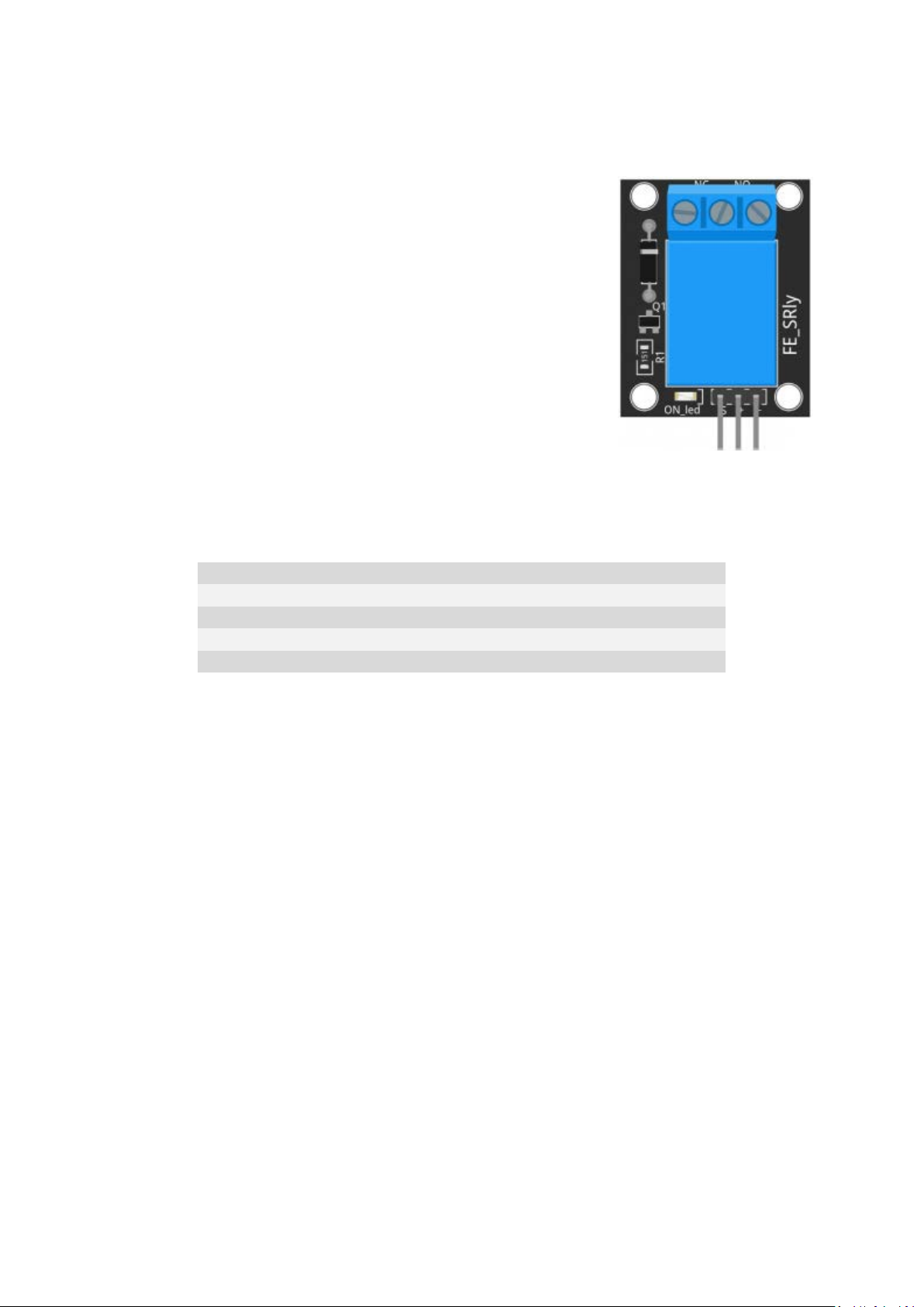
The Relay Module is used to control AC or DC circuits. The relay acts as
a switch that responds to a signal received from the Arduino. It has an
integrated LED that indicates if the signal is high or low.
Commonly used in IoT projects to control lights and other electronic
appliances.
The module consists of a resistor, an LED, a diode and a 5VDC relay
capable of handling up to 250VAC and 10A.
On the control side of the board there are 3 pins for signal, power and
ground. On the load side there are 3 contacts, NC (Normally Closed), Common and NO (Normally
Open).
Pinout and Connection to Arduino
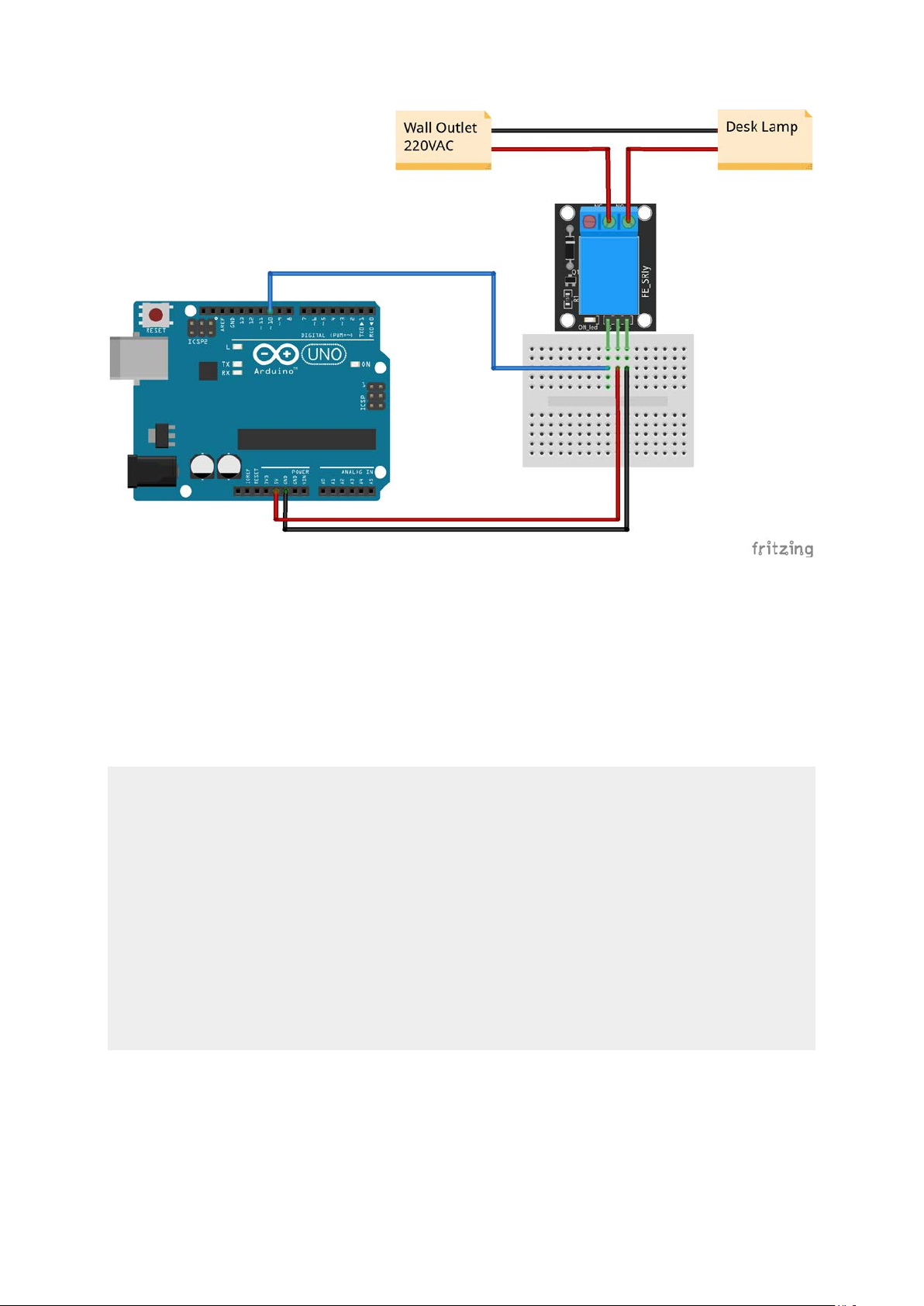
For the DC part of the circuit connect S (signal) to pin 10 on the Arduino, also connect the Power line
(+) and ground (-) to +5 and GND respectively.
On the AC side connect your feed to Common (middle contact) and use NC or NO according to your
needs.
NO (Normally Open) will get power when (S) is high, NC (Normally Closed) gets disconnected when
(S) is high.
Always be very careful when experimenting with AC, electrical shock can result in serious injuries!
Page 2
Arduino Example Sketch
The following Arduino sketch will turn the relay on/off every second. We'll connect a desk lamp to
the relay using the NO (Normally Open) connection so the lamp is off when the relay is off. Running
the sketch will cause the lamp to light up intermittently.
int relay = 10; //Pin 10
void setup()
{
pinMode(relay,OUTPUT); // Define the port attribute as output
}
void loop()
{
digitalWrite(relay,HIGH); // turn the relay ON
delay(1000);
digitalWrite(relay,LOW); // turn the relay OFF
delay(1000);
}
 Loading...