

Fritz Gegauf Bernina artista 630, Bernina artista 640 Service Manual
Service Manual
© Fritz Gegauf Ltd.
BERNINA sewing machines
8266 Steckborn
Switzerland
Service-Manual_artista_630_640_english_V4.01_032069_50_04.doc 1
artista 630-640
Version 4

Chapter 1
General information
1.1 Safety Regulations
Caution!
All electrical and electronic components operate at dangerous voltages. Remov e the mains plug
before making any adjustments to the machine. Wait about 30 seconds after removing the plug
(capacitor discharge).
This service manual is intended to help with minor repairs and adjustments.
The instructions do not claim to be complete or comprehensive. The manual does not provide guidance
for complete assembly or disassembly.
Important:
To enable the work described to be performed correctly, the se wing and embroidery computer
must be in good mechanical and electrical condition (running smoothly, properly oiled and all
leads connected)! When adjustments are carried out in the correct order, the sewing/embroidery
computer will function without a problem.
It is important that only devices approved and distributed by BERNINA® are connected to the
sewing/embroidery computer ports.
When servicing or repairing, always use genuine parts and original accessories, either those
delivered with the machine or purchased afterwards.
These are the following:
• Mains cable
• Foot control unit
• Buttonhole foot
• Presser foot 1
• Bobbin case with bobbin
• Other accessories
• BERNINA stitch length regulator (BSR) foot (if applicable).
The Service Manual and Instructions are protected by copyright laws. These documents are
delivered exclusively to the recipient. It is forbidden to copy, distribute, forward, publish or to
reproduce them in any form without the express prior consent of Fritz Gegauf AG, BERNINA
Steckborn, Switzerland. It is also forbidden to record this Service Manual and Instructions on any
retrieval system, or to translate it, or parts of it, into any human or computer-related language of
any kind, whether electronically, mechanically, magnetically , or otherwise. Furthermore, it is
prohibited to disclose the Service Manual and Instructions to third parties without the express
written approval of Fritz Gegauf AG, BERNINA Sewing machine manufacturers, Steckborn,
Switzerland.
This Manual is subject to revisions without notice. The recipient is responsible for updating the
information provided by Fritz Gegauf AG, BERNINA Sewing machine manufacturers, Steckborn,
Switzerland.
Masthead
Author: Hans Peter Horn
Layout/typesetting: Hans Peter Horn
Print:
Service-Manual_artista_630_640_english_V4.01_032069_50_04.doc 2
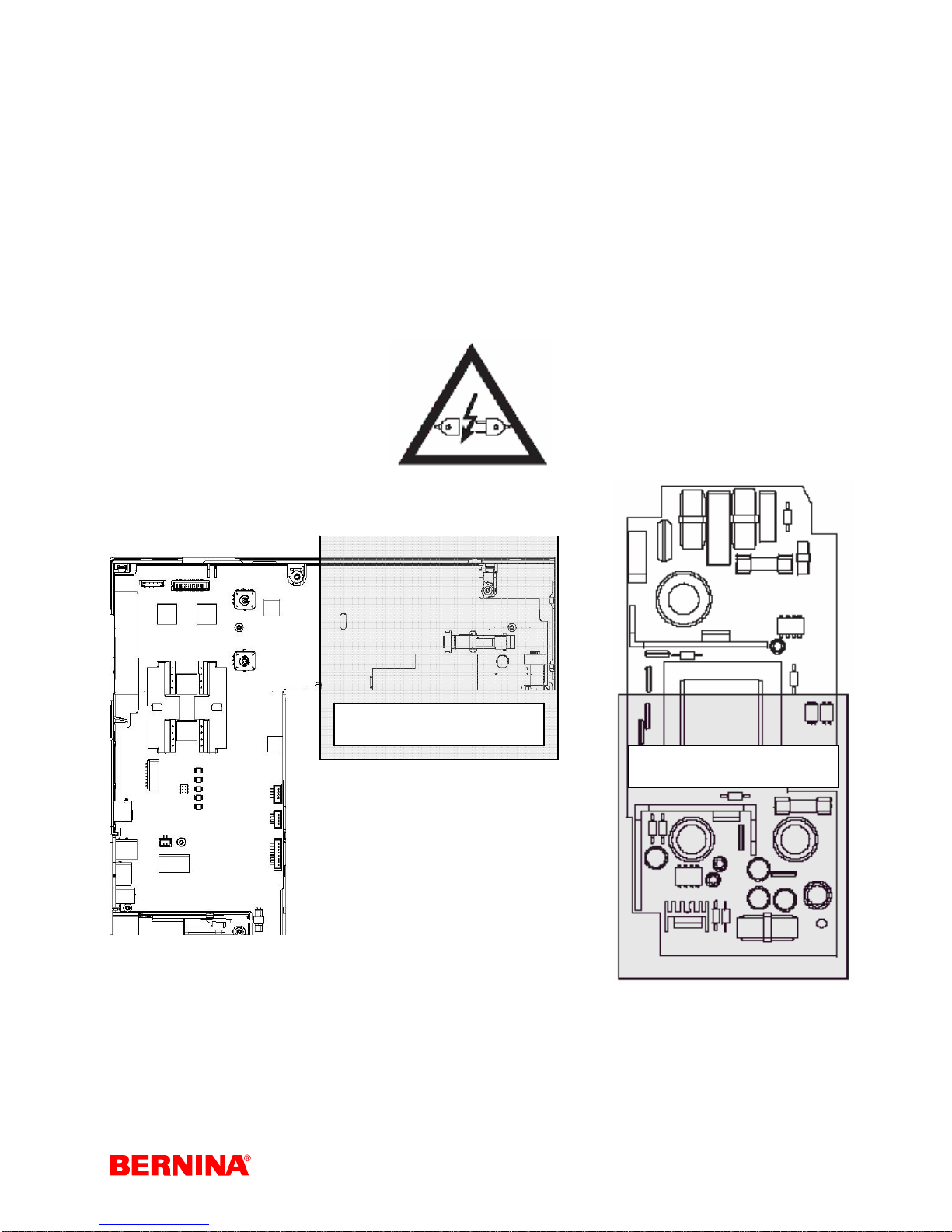
1.2 Warning: Dangerous voltage levels!
Caution!
The L-Print power circuitry, the S-Print CFL voltage supply and the mains cable all carry dangerous
voltages.
For your own safety do not touch the L-Print and S-Print until about 30 seconds after the main voltage has
been switched off. This is the time required for the capacitors to discharge.
Warning!
The sewing/embroidery computer may only be connected to the mains supply when the chassis covers
are mounted. Work on the L-Print, S-Print and mains cable may only be carried out when the mains plug
has been removed from the mains supply.
Caution! High voltage!
Caution! High voltage!
Service-Manual_artista_630_640_english_V4.01_032069_50_04.doc 3

1.3 Contents
Chapter 1 General information.........................2
1.1 Safety Regulations.....................................2
1.2 Warning: Dangerous voltage levels!..........3
1.3 Contents.....................................................4
1.4 Note on Electrostatic Discharge (ESD)......6
1.5 Tools and gauges.......................................7
Chapter 2 Description of technical details
and electronics ...................................................9
2.1 BERNINA artista 630/640 technical
specifications....................................................9
2.2 Cleaning...................................................10
2.3 Block diagram ..........................................11
2.4 PCBs, plugs and cables...........................12
2.5 General functions of the PCBs.................16
Chapter 3 Functional check and diagnostic
instructions.......................................................18
3.1 Functional check ......................................18
3.2 Diagnostic instructions.............................18
3.3 Sewing-off (a-640 must be sewn-off with
the head cover fitted (light will affect the
threader sensor).............................................19
3.4 External cleaning......................................19
Chapter 4 Replacing Assemblies....................20
4.1 Removing covers .....................................20
4.2 Thread pre-tensioner................................21
4.3 Vertical spool pin......................................22
4.4 Horizontal spool pin and rear thread-guide
eyelet..............................................................22
4.5 Carrying handle........................................23
4.6 Magnifying-glass holder and thread cutter24
4.7 S-Print, keypads, front panel, RET-Print,
touch screen, display and side cover (plugs).25
4.8 P-Print ......................................................27
4.9 L-Print.......................................................28
4.10 CFL.........................................................29
4.11 Presser foot lifter sensor (micro switch).29
4.12 Buttonhole sensor PCB..........................31
4.13 Main motor (complete unit only).............31
4.14 Stitch width stepping motor....................32
4.15 Stepping motor, stitch length and
crankshaft.......................................................33
4.16 Presser foot pressure sensor.................34
4.16 Presser foot pressure sensor.................35
4.17 Winder motor..........................................35
4.18 Base shaft ..............................................36
4.19 artista 630 hook race ring.......................38
4.20 artista 640 stitch plate holder.................39
4.21 Rotary hook (RH), cutting blade and hook
drive belt in artista 640...................................40
4.22 Drive belt (synchronization of main and
base shaft)......................................................41
4.23 artista 630 upper thread tension............41
4.24 artista 640 upper thread tension............42
4.25 Thread take-up lever, thread take-up lever
crank, needle bar and link piece ....................43
Chapter 5 Adjustments...................................44
5.1 Tensioning the drive belt..........................44
5.2 Tensioning the base shaft belt.................44
5.3 artista 640 hook drive belt tension...........45
5.4 Bobbin winder..........................................45
5.5 Position of the head frame plate..............46
5.6 Presser foot fixation.................................46
5.7 Presser foot height...................................47
5.8 Darning foot height ..................................47
5.9 Straight stitch needle position (needle
distribution) ....................................................48
5.10 Stitch width limiter..................................48
5.11 Thread guide plate plate adjustment on
artista 630......................................................49
5.12 Position of driver in hook race of
artista 630......................................................49
5.13 Thread passage on artista 630..............49
5.14 Bobbin case retainer position on
artista 640......................................................50
5.15 artista 630 CB hook, synchronization,
feed and needle drive....................................51
5.16 artista 640 RH hook, synchronization,
feed and needle drive....................................53
5.17 Needle/hook distance............................54
5.17 Needle/hook distance............................55
5.18 artista 630 needle height .......................56
5.19 artista 640 needle height .......................56
5.20 Threader ................................................57
5.21 Feed-dog position in stitch plate............57
5.22 Feed-dog height.....................................58
5.23 Position of synchronizing disc (rough-
adjustment)....................................................59
5.24 Basic balance setting.............................59
5.25 Basic presser foot lifter setting
(Free Hand System (FHS))............................61
5.26 Thread tension release..........................62
5.27 Basting and long stitch device
artista 640......................................................62
5.27 Basting and long stitch device
artista 640......................................................63
5.28 artista 630 CB hook lower thread tension
(basic setting).................................................64
artista 640 RH hook lower thread tension
(basic setting).................................................64
5.29 artista 630 upper thread tension (basic
setting)...........................................................65
5.30 artista 640 upper thread tension (basic
setting)...........................................................65
5.31 Thread regulator spring .........................66
Chapter 6 Service Program............................67
6.1 Starting the test program.........................67
6.2 Virtual keyboard.......................................69
6.3 Menu 1 – Service information..................70
1a Sewing/embroidery computer basic data:
...................................................................70
Service-Manual_artista_630_640_english_V4.01_032069_50_04.doc 4

1b Sewing/embroidery computer soft- and
firmware data:............................................71
1c Sewing/embroidery computer operating
time data....................................................71
1d Sewing/embroidery computer stitch
counter data:..............................................72
1e BSR (BERNINA Stitch Regulator) data:72
1f Sewing/Embroidery computer servicing
data:...........................................................72
1g Saving of customer data.......................73
1h Customer data: .....................................73
1i Dealer data:............................................73
1j Log file....................................................74
6.4 Menu 2 – screen and beeper..................74
2a Touch screen calibration:......................74
2b LCD (screen):........................................75
2c Blank black LCD (screen): ....................75
2d Blank white LCD (screen):....................75
2e Speaker test:.........................................76
6.5 Menu 3 – Signals and sensors.................76
3a Stitch width and stitch length adjusting
knobs functions..........................................76
3b Functioning of keyboard: ......................76
3c Start/stop unit (SSU) slide control:........77
3d & 3d1 Foot control: ...............................77
3f Presser foot pressure sensor:................78
3g Presser foot lifter micro switch:.............78
3h Winder motor micro switch: ..................78
3i Feed-dog drop light barrier: ...................79
3j artista 640 lower thread indicator:..........79
3k Upper thread indicator: .........................79
3l BERNINA Stitch Regulator (BSR) foot: .80
3m Buttonhole signals A & B.....................80
3n Positioning PCB (P-Print): ....................81
3n Mechanical fine-adjusting of P-Print:....81
3q USB host interface:...............................82
3s EMB interface:.......................................82
3t Foot control interface:............................82
3u BSR foot interface:................................83
6.6 Menu 4 – Motor functions.........................83
4a Stitch length stepping motor:................83
4b Stitch width stepping motor:..................84
4c artista 640 upper thread tension stepping
motor:.........................................................84
4d All stepping motors:..............................84
4f Stitches per minute (SPM) calibration:..85
4g Standard SPM (stitches per minute)
speed:........................................................86
4h Calibrating the SSU (Start/stop unit):...86
4i Standard SSU speed:............................86
4j Automatic start/stop:..............................87
4k Winder motor:.......................................87
4l Basting magnet: artista 640...................87
4m Thread cutter clamping magnet:
artista 640..................................................88
4n Thread cutting process: artista 640......88
6.7 Menu 5 – Adjustments.............................89
5a Sewing-off (customer’s view): ..............89
5b Electronic balance calibration:..............90
5b Mechanical balance fine-adjusting:......90
5b Mechanical balance fine-adjusting:......91
5b Electronic balance fine-adjusting:.........91
5c Buttonhole calibration:..........................92
5e Presser foot pressure sensor calibration
(end stops):................................................92
5f Electronic upper thread tension:
artista 640..................................................93
5g BERNINA Stitch Regulator (BSR) foot
sewing program:........................................93
5h BSR foot update:..................................94
5i Resetting artista 640 upper thread tension
to default....................................................94
5j Resetting to factory settings (Reset All):94
6.8 Menu 6 – Embroidery module (EMB)......95
6a Embroidery module basic data:............95
6b Free-arm adapter sensor:.....................96
6c X-axis sensor:.......................................97
6d Y-axis sensor:.......................................97
6e X- and Y-movement of stepping
motors:.......................................................98
6f Movement of stepping motor X: ............98
6g Movement of stepping motor Y: ...........98
6h Hoop reference position: ......................99
6i Embroidering using the test design:......99
6j Customer’s embroidery view:..............101
Chapter 7 Updating.......................................101
7.1 Updating of sewing/embroidery
computer......................................................101
7.2 BSR update............................................102
5h BSR foot update:................................102
7.3 Update – alternative access ..................103
8. Chapter Lubrication Plan .........................104
8.1 Lubrication Plan artista 630...................104
8.2 Lubrication Plan artista 640 supplementary
to artista 630................................................105
Service-Manual_artista_630_640_english_V4.01_032069_50_04.doc 5

1.4 Note on Electrostatic Discharge (ESD)
Electrostatic charges are caused by:
• a person's walking (influence) over synthetic tilled or carpeted floor
• friction between and separation of two insulating materials (triboelectricity)
If this static electricity discharges through electronic components, these may be
partially or irreparably damaged. Electrostatically charged persons represent the
greatest danger for components. This can be dissipated by controlled electrostatic
discharge.
Protection of electrical and electronic components against electrostatic
discharges
Be sure to follow these important guidelines:
1. Always work at a stationary, ESD-compliant workstation equipped with the appropriate protective
devices including conductive table and floor mat, earth connection box and earthing wristband when doing
service work.
The cable of the earthing wristband must have a built-in resistance of 1 M ohm to ensure p rotection.
2. Always put on an earthing wristband before starting to work. Always remove any synthetic parts like
plastic bags, covers etc. from your workstation.
3. Only open ESD protective packaging at your ESD-proof workstation while wearing an earthing
wristband. Electronic components must be placed on conductive table mats only. Packing is carried out
under the same conditions.
4. Only use conductive plastic/foil pouches and ESD transport boxes for dispatching electronic
components – even if the components might be faulty.
5. Treat faulty PCBs the same as good ones to prevent addition harm.
Service-Manual_artista_630_640_english_V4.01_032069_50_04.doc 6
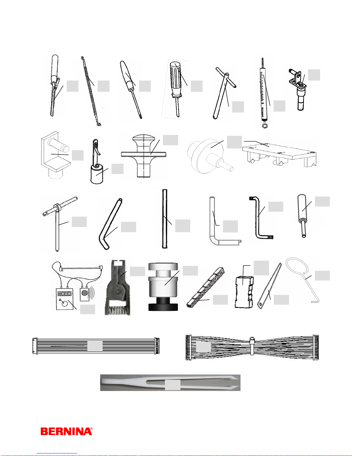
1.5 Tools and gauges
Required tools and gauges (commercially available, not available from BERNINA): Multimeter, ICExtraction tool and TORX screw driver sizes: No. 6, 8, 9, 10, 12, 15, 20, and 25.
1 2 3 4
7
8
12
9
13
19
10
14
20
15
11
5
6
17
16
22
24
18
25
Service-Manual_artista_630_640_english_V4.01_032069_50_04.doc 7
27
26
21
23
No. Part number Description No. Part number Description
398 083 030 Circlip mounting tool
1
398 112 030 Spring mounting tool
2
398 097 030 Rectifying tool bobbin case
3
spring
001 361.70.00 Eccentric key
4
001 357.70.00 Rectifying tool driver/hook
5
play
006 038.50.00 Spring balance gauge
6
001 358.70.00 Lower thread tension CB
7
006 543.70.01 Lower thread tension RH
8
398 080 040 Upper thread tension
9
006 765.71.00 Hook race gauge CB
10
032 051.70.00 Centering gauge 640
11
Parallel setting gauge (Set)
030 349.70.00 Pinning tool short (Set)
12
030 430.51.00 Pinning tool
12
001 356.50.00 Angular pinning tool
13
007 937.50.00 Pinning tool base shaft
14
031 563.50.00 Eccentric key head frame
15
007 993.50.00 Angular key Torx 8
16
030 883.50.00 Distance gauge for auto
17
threader
Commercially
18
available
Commercially
19
available
031 939.70.00 Bobbin winder gauge
20
398 031 133 Presser foot height
21
398 024 030 Feed-dog height
22
398 022 030 Feeler gauge 0,3 mm
22
398 111 030 Feeler gauge 0,15 mm
23
030 652.50.00 Pinning tool for Stepp motor
24
023 054.50.01 Service cable 50mm 10 pol.
25
031 134.50.01 Service cable 50mm 30 pol.
26
Commercially
27
available
031 950.70.00 BERNINA USB Stick 64MB
Digital Multimeter
IC-Extraction tool (EEPROM)
SL
Composite Tweezers
(disconnecting cables)
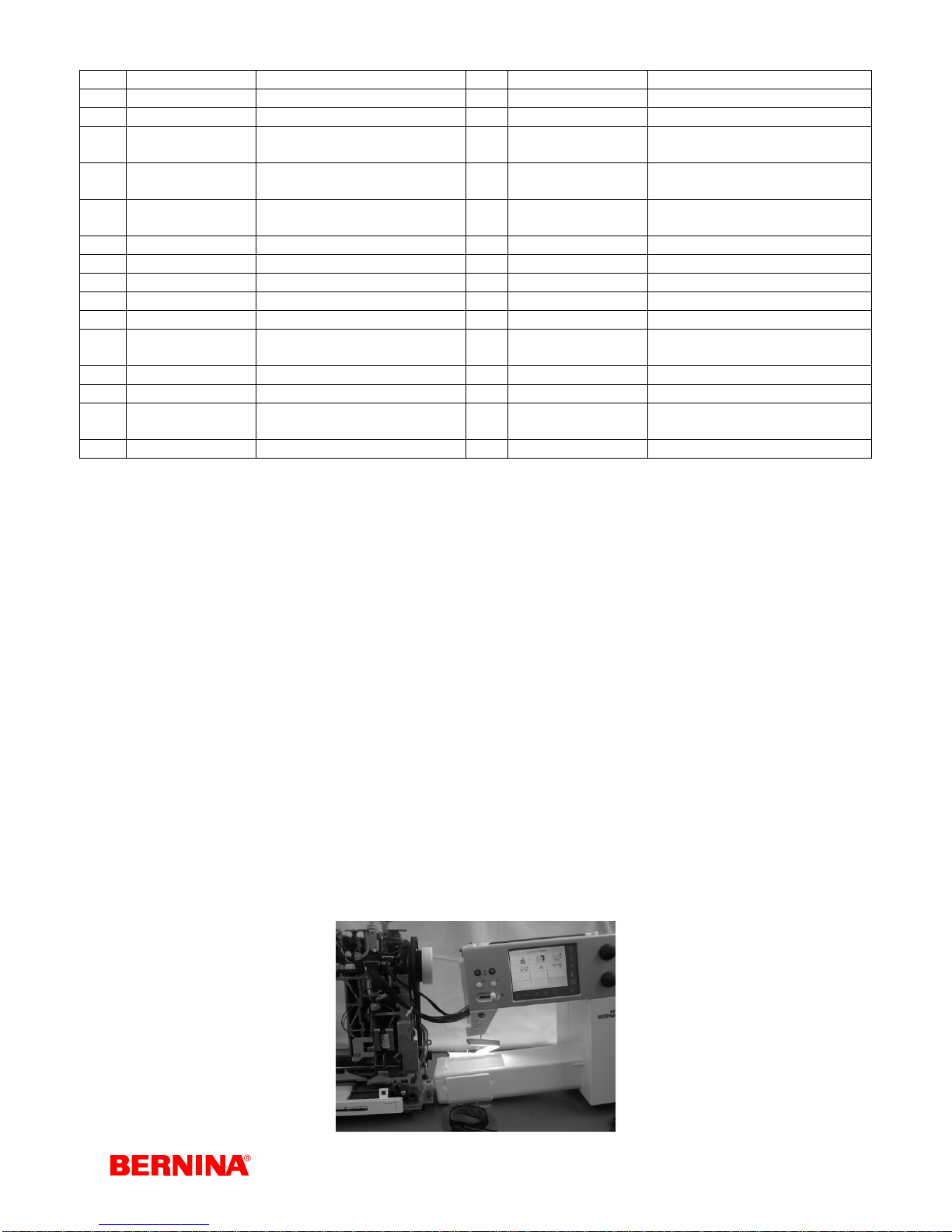
1.6 Where and how to use the service cables # 25 and 26
Where to use:
• In order to have the artista 630 and 640 machines under power whilst the covers have been taken
off, it is necessary to use the service cables 023 054.50.01 (50mm 10 pole) and 031 134.50.01
(50mm 30 pole).
How to use:
1. Observe ESD regulations (page 6).
2. Remove the power cord
3. Remove the covers (pages XXXX). The removed covers must be placed on the ESD mat.
4. Attach the service cables very carefully (straight) to the S-Print and P-Print. The artista 630 only
needs the 30 pole cable. The artista 640 needs also the 10 pole cable.
5. Attach an external CFL sewing light to the S-Print.
Note: Without the CFL sewing attached, the screen will not have any background lighting!
6. Fit the connection cable L-Print / S-Print.
7. Place both the back and front covers together and using the snapper clips, clip together.
8. When necessary the motor cable can also be connected.
9. Connect the power cable and switch the machine on. In order to get into the service program one
has to press the reverse button whilst switching on the machine.
Attention: Make sure that no cable is pinched, trapped or otherwise damaged.
Service-Manual_artista_630_640_english_V4.01_032069_50_04.doc 8

Chapter 2
Description of technical details and electronics
2.1 BERNINA artista 630/640 technical specifications
Features artista 630 artista 640
Max. stitch length forward in mm...................5..............................................5
Increment in mm............................................0,15.........................................0,15
Max. stitch length reverse in mm...................5..............................................5
Stitch width in mm .........................................5,5...........................................9,0
Increment in mm............................................0,23.........................................0,23
Data interface................................................USB.........................................USB
Hook system..................................................BERNINA CB..........................BERNINA RH
Needle system...............................................130/705 H ..............................130/705 H
Adjusting needle............................................130/705H TCN 80...................130/705H TCN 80
Sideways motion ...........................................no............................................no
Feed-dog drop...............................................yes ..........................................yes
Feed-dog drop via FHS.................................yes ..........................................yes
Needle positions............................................11............................................11
Stitch programs:
Total number of buttonhole types..................7..............................................8
Buttonhole length measuring system............yes ..........................................yes
Quilting stitches.............................................25............................................28
Total number of utility stitches.......................26............................................26
Total number of decorative stitches ..............145..........................................189
Alphabets ......................................................4..............................................5
Eyelets...........................................................2..............................................2
Total number of stitch patterns......................250..........................................300
Functions:
Automatic basic settings................................yes ..........................................yes
Display of recommended optimum settings ..yes ..........................................yes
Display of selected stitch...............................on display................................on display
Clear (clr) button............................................yes ..........................................yes
Balance..........................................................electronically...........................electronically
Sideways mirroring........................................yes ..........................................yes
Permanent reverse sewing............................yes ..........................................yes
Memory (mem)..............................................yes ..........................................yes
Pattern end....................................................yes ..........................................yes
Securing at pattern beginning/ending............yes ..........................................yes
Upper thread indicator...................................yes ..........................................yes
Lower thread indicator...................................no............................................yes
BSR – BERNINA stitch length regulator........yes ..........................................yes
Integrated threader........................................yes ..........................................yes
Hopper mechanism .......................................yes ..........................................yes
Longstitch setting...........................................no............................................yes
Adjustable presser-foot pressure ..................yes ..........................................yes
Free Hand System (FHS) presser foot lifter..yes ..........................................yes
Automatic upper thread tension ....................no............................................yes
Automatic lower thread cutter........................no............................................yes
Operating controls
Screen ...........................................................graphic LCD............................graphic LCD
Colors ............................................................256..........................................256
Size in mm (inch)...........................................80x60 (3.2x2.4).......................80x60 (3.2x2.4)
Number of pixels............................................320x240..................................320x240
Service-Manual_artista_630_640_english_V4.01_032069_50_04.doc 9
Features artista 630 artista 640
Screen backlighting.......................................yes/white.................................yes/white
Direct stitch/function selection.......................yes/touch screen.....................yes/touch screen
Stitch width bar display..................................yes ..........................................yes
Stitch length bar display ................................yes ..........................................yes
Integrated service program............................yes ..........................................yes
Drive/power unit
Universal power PCB (L-Print), 100-240 Voltyes ..........................................yes
Power max.....................................................100 W......................................100 W
Motor..............................................................DC/65W30V............................DC/65W30V
Sewing speed................................................100-900 S.p.M ........................100-900 S.p.M
Embroidery stitching speed ∅ .......................600 S.p.M................................600 S.p.M
Needle stop ...................................................yes ..........................................yes
Needle stop via foot control...........................yes ..........................................yes
Main power switch.........................................yes ..........................................yes
Mechanical data / housing
Diametral capacity in mm .............................190x110 /215..........................190x110 / 215
(inch)..............................................................(7.5x4.3 / 10.2)........................(7.5x4.3 / 10.2)
Overall length in mm (inch)............................385 (15)...................................385 (15)
Overall width in mm (inch).............................175 (7).....................................175 (7)
Overall height in mm (inch)............................308 (12)...................................308 (12)
Sewing light ..................................................CFL.........................................CFL
Presser foot level in mm................................7,5...........................................7,5
Weight in kg (without accessories) (lbs)........approx. 9.7 (approx. 21) .........approx. 9.7 (approx. 21)
2.2 Cleaning
Remove covers and clean.
Electrostatic charging may occur during cleaning. To prevent this, use antistatic office-equipment cleaning
agents.
We use and recommend BASF’s SURFACE CLEAN surface cleaner
It forms a protective film against static electricity, and is suitable for both plastic and metallic surfaces.
Inside parts
Dust, lint, thread and fabric remnants can accumulate inside the machine behi nd the covers and may lead
to malfunctions.
In the head frame area, this frequently occurs in particular in the thread take-up (joints), the main shaft
(behind the balance piece) and the thread tension device.
In the base area it occurs in:
The main and base shaft belts and their tension units can also be affected by the accumulation of dust,
lint, thread and fabric remnants, as well as by belt residue.
the bobbin case,
the feed-dog,
the hook,
the hook drive,
the hook race,
the base shaft (lift and advance eccentric),
and in the toothed rack.
Attention!
Never use alcohol,
petrol, spirits or any
corrosive fluids, or
abrasive pastes!
Service-Manual_artista_630_640_english_V4.01_032069_50_04.doc 10
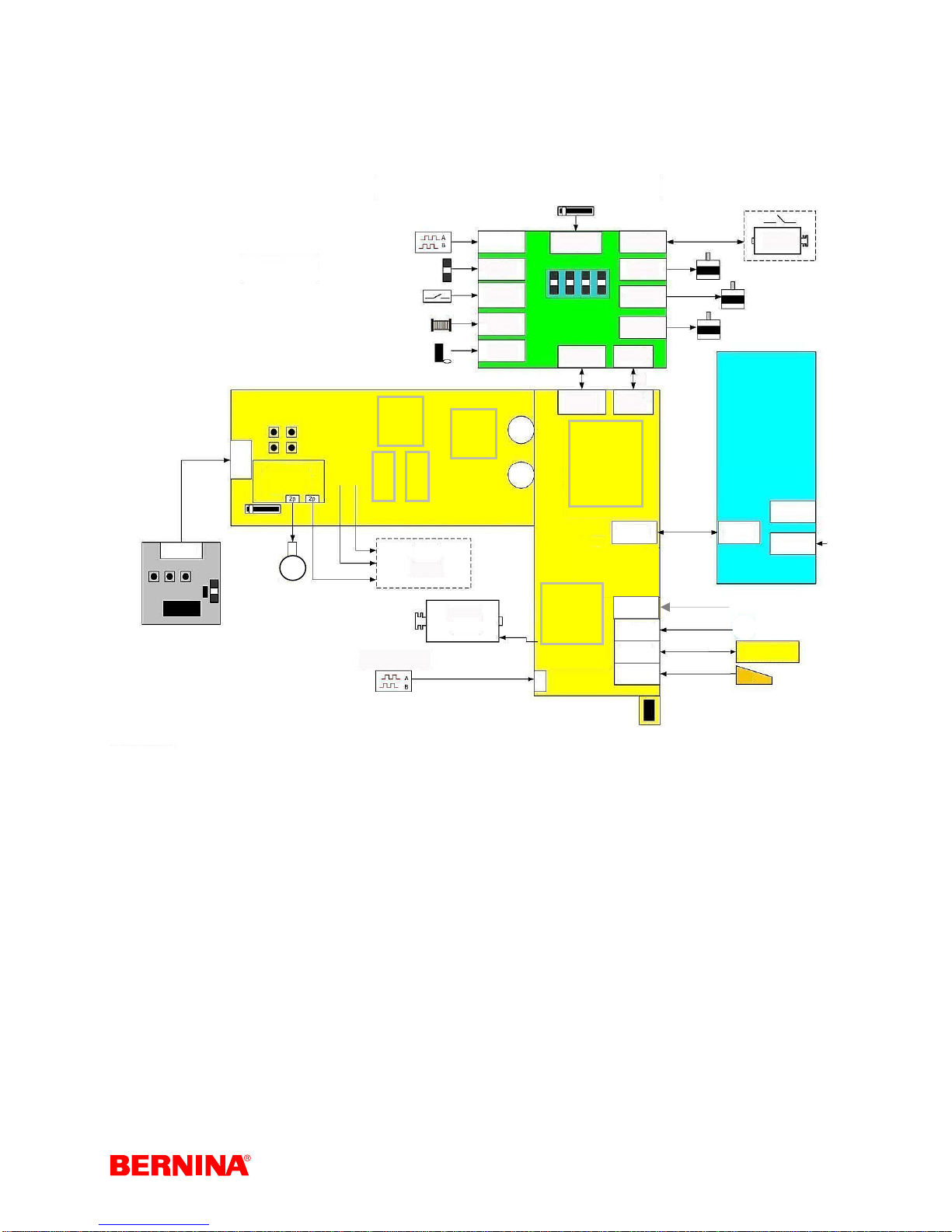
2.3 Block diagram
The electronics of the BERNINA artista 630/640 are primarily accommodated in three main modules
(PCBs) – the L-Print (power PCB), the P-Print (positioning PCB) and the S-Print (control via microprocessor).
S-Print
Upper Thread
Sensor
RET-
RETPrint
CFL Background
Light Converter
Sewing Light
Proce
ssor
S
Flash
D
R
A
M
LCD / Background-
Lighting
Touch Screen
Lower Thread Sensor
FPGA
Main Motor
30 V / DC
Buttonhole
Sensor
Threader
Sensor
Presser Foot
Sensor
Clamping
Magnet Sensor
BSR
Presser Foot
Pressure
P-Print
S-Print
P-Print
Motor Drivers
S-Print
Main Motor Drive
Stepping
Winder Motor
Motor SB
Motor SL
Motor SP
S-Print
P-Print
L-Print
USB Client
USB Host
EMB
Foot Control
Winder
Motor DC
Stitch width
Stitch length
Upper thread tension
L-Print
Mains Switch
S-Print
Foot Control Unit
Mains Plug
USB Stick
PC
EMB Module
Sensor Feed-Dog Drop
Service-Manual_artista_630_640_english_V4.01_032069_50_04.doc 11

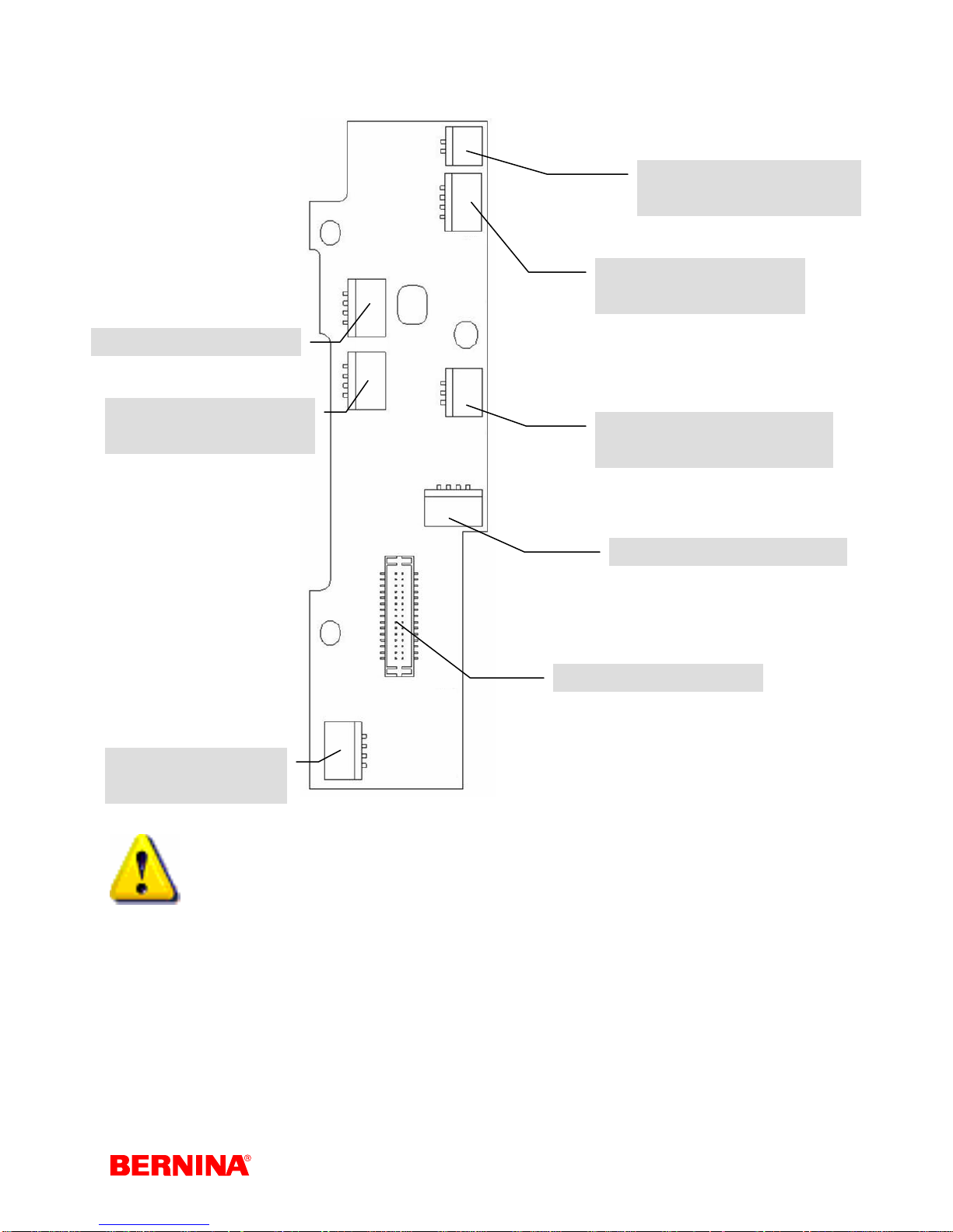
2.4 PCBs, plugs and cables
artista 640 positioning PCB
4 Pole Red = BSR sensor
4 Pole white = Buttonhole
sensor
5 Pole white = Threader
PCB and basting magnet
2 Pole black = Presser-foot
position micro switch
4 Pole white = Stitch width
stepping motor
4 Pole yellow = Upper thread
tension motor
3 Pole red = Presser foot
pressure control
2 Pole white = Clamp magnet
4 Pole yellow = Winder motor
30 Pole white = S-Print
4 Pole blue = Stitch
length stepping motor
10 Pole white = S-Print
Note:
Never connect or disconnect the connecting cables when the machine is powered!
Service-Manual_artista_630_640_english_V4.01_032069_50_04.doc 12
artista 630 positioning PCB
4 Pole Red = BSR sensor
2 Pole black = Presser-foot
position micro switch
4 Pole white = Stitch width
stepping motor
4 Pole white = Buttonhole
sensor
4 Pole blue = Stitch
length stepping motor
3 Pole red = Presser foot
pressure control
4 Pole yellow = Winder motor
30 Pole white = S-Print
Note:
Never connect or disconnect the connecting cables when the machine is powered!
Service-Manual_artista_630_640_english_V4.01_032069_50_04.doc 13
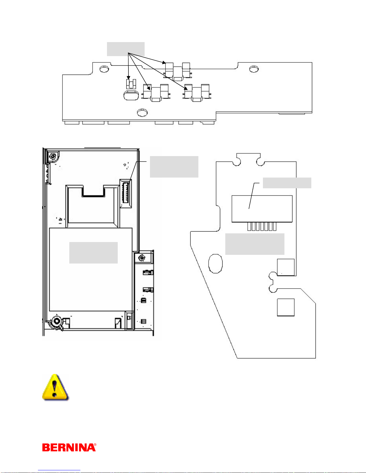
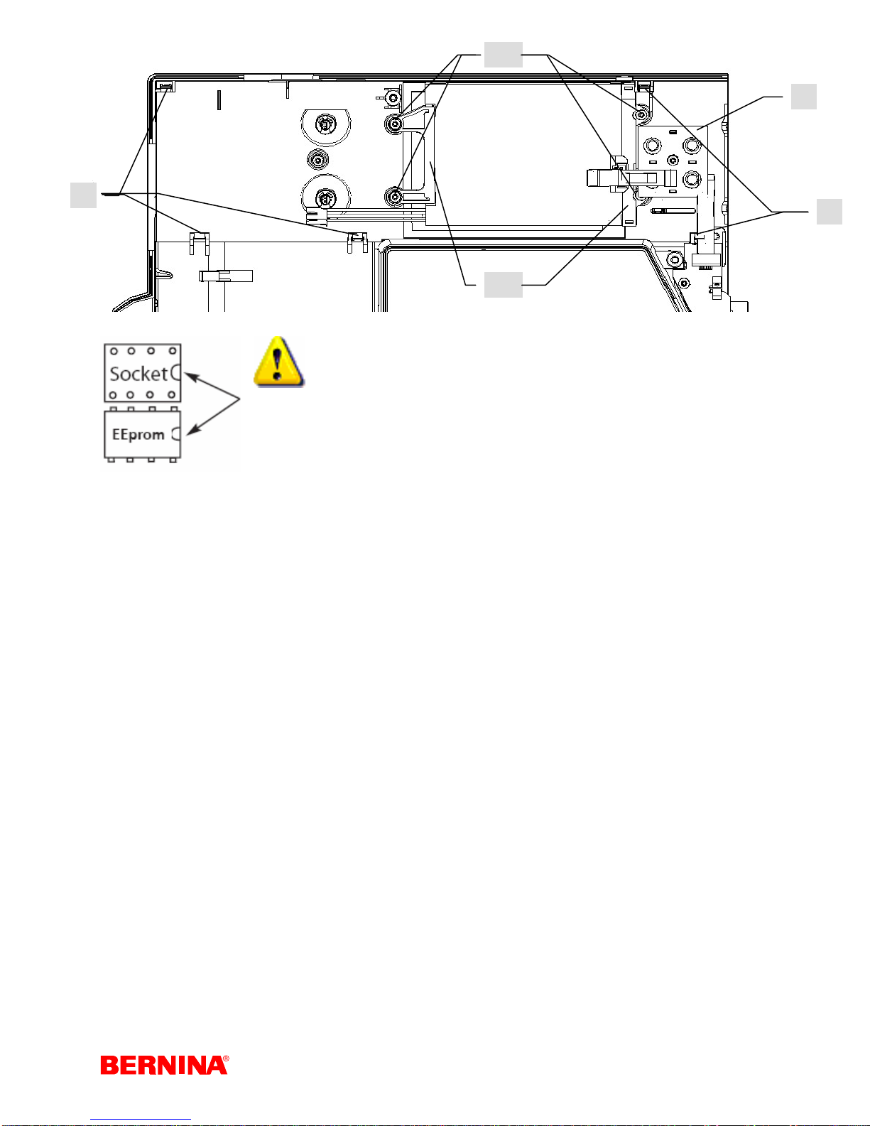
P-Print (artista 630 & 640) reverse side
Sensors
L-Print 8 pole
white
S-Print 7 pole
Ret-Print
L-Print
Upper thread
sensor
Note:
Never connect or disconnect the connecting cables when the machine is powered!
Service-Manual_artista_630_640_english_V4.01_032069_50_04.doc 14
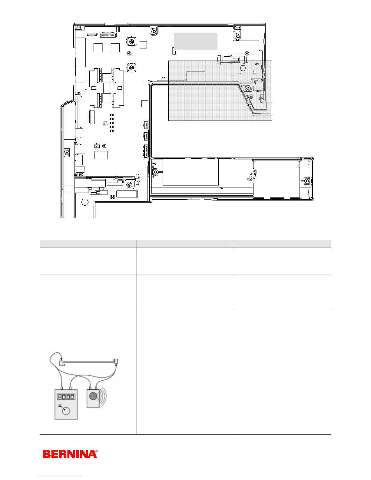
S-Print
Caution!
High voltage !
Ribbon cable function
What to Test What to adjust Desired status
Electrical resistance of cable
Visual check
Electronic measurement by
ohmmeter or continuity tester
(beeper)
Disconnect mains plug, remove
covers and unplug cables from
both printed circuits
Set measuring instrument to
beeper or Ohm area.
Check each cable wire.
This involves placing the
measuring tips on the top of the
connector against the metal
cutters to check each wire
against the other.
Check cables for damage, short
circuits, and line disconnections
Check plug and socket for
damage, bent or loose contacts
Each wire individually:
If the wire is OK:
• Ohm on the ohmmeter:
beep signal on beeper.
Defective wire:
Ohm on Ohmmeter: no beep
signal on beeper (interruption).
Each wire against the other
wires:
If the wire is OK:
Ohm on Ohmmeter: no beep
signal on beeper
Defective wire:
• Ohm on ohmmeter; beep
signal on beeper (short
circuit, squashed wires)
Service-Manual_artista_630_640_english_V4.01_032069_50_04.doc 15
2.5 General functions of the PCBs
The microcomputer on the S-Print receives an analogue signal from the foot control which is converted
into a digital signal and reported as a nominal value. The motor r.p.m is adjusted to the required value by
comparison of the predetermined and actual values. When the foot control is released (nominal value
zero) the microcomputer switches on the electrical brake. The motor is stopped very quickly in the
required needle position.
On switching on the sewing/embroidery computer, the stepping motors may be in any given position. The
microcomputer control memory may also have any given value. The stepping motors are moved to their
pinning position by means of a command from the microcomputer to give a defined situation. This position
is then registered and set to zero in the memory. This zero position then allows any stitch program to be
selected and sewn.
The S-Print controls the processes between the individual stepping motors, evaluates the signals of the
sensor and shows the results on the display.
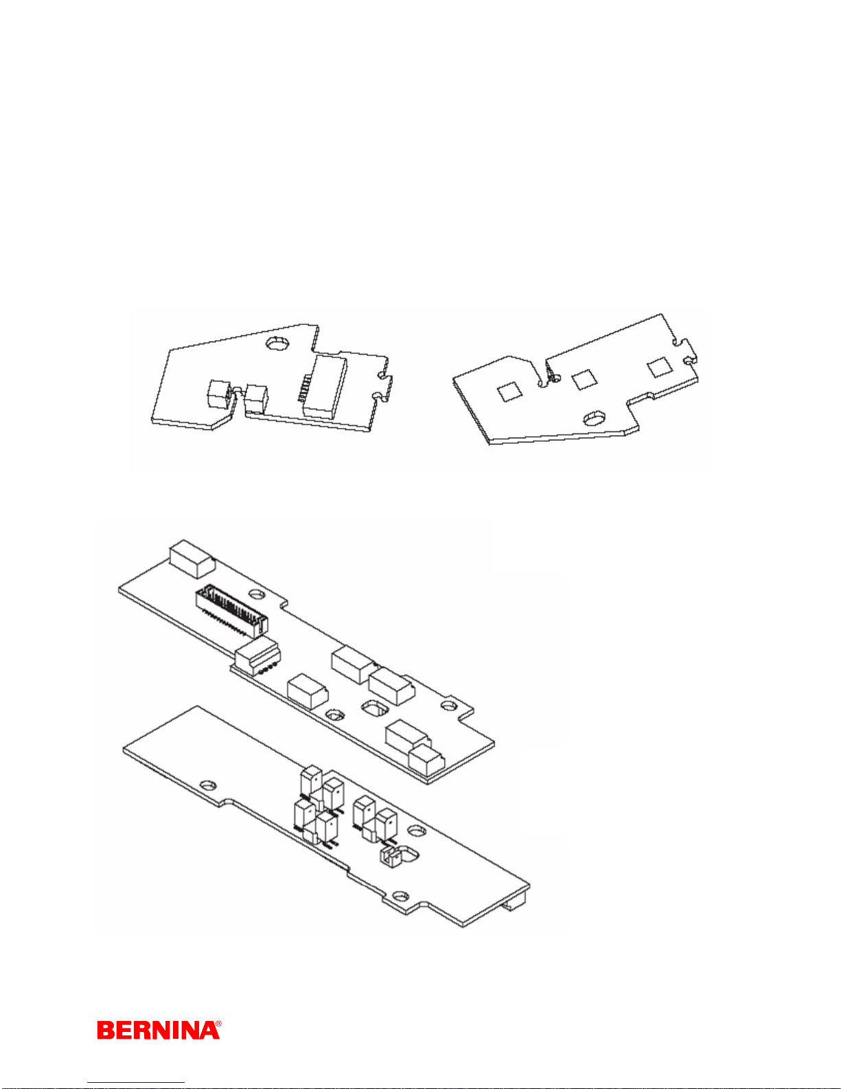
RET-Print (return)
P-Print
The RET-Print
accommodates three
buttons and the upper
thread indicator light
barrier.
The P-Print accommodates
the synchronizing disc light
barriers, and the motor and
sensor connections.
Service-Manual_artista_630_640_english_V4.01_032069_50_04.doc 16
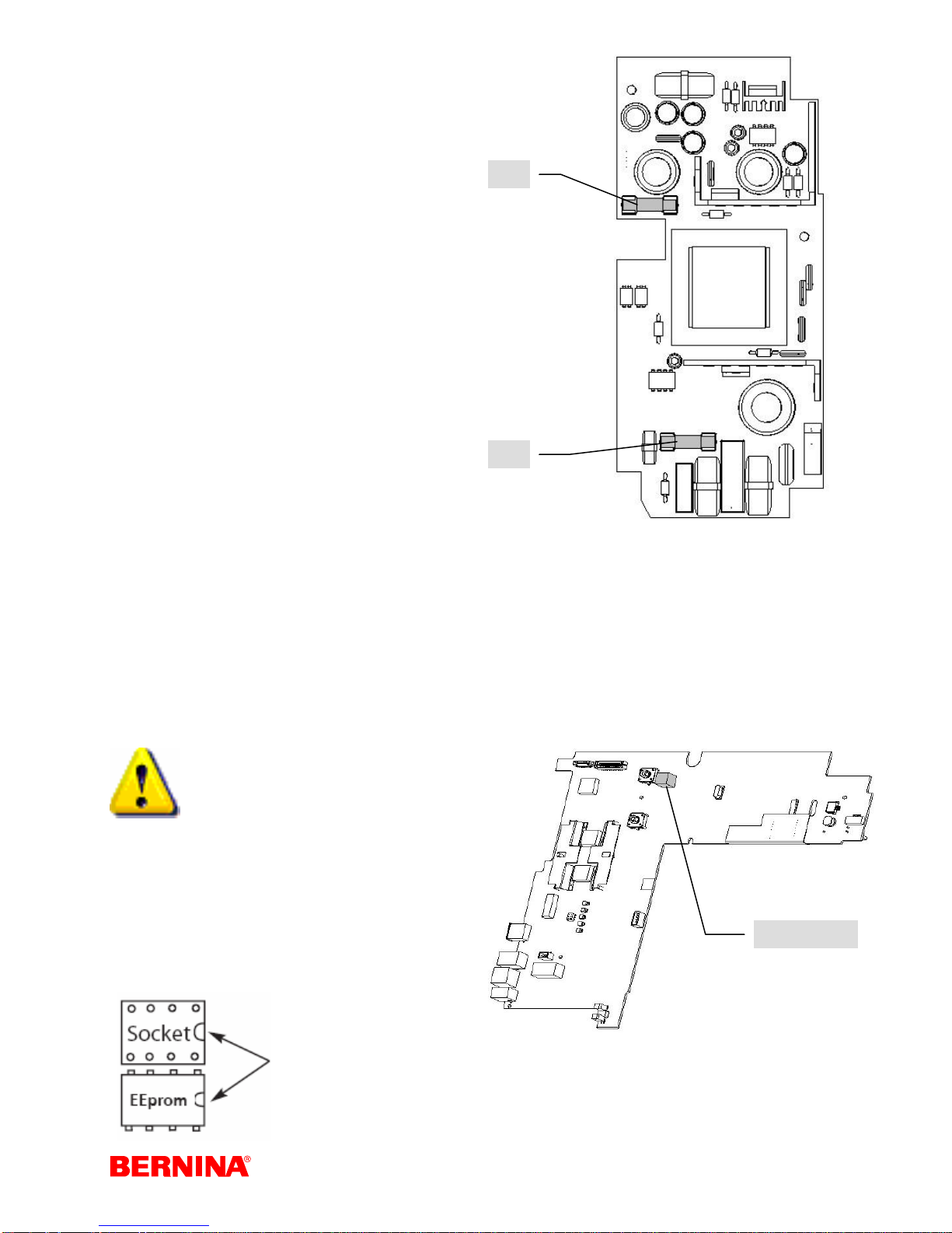
Universal L-Print (power)
The power PCB (L-Print) is installed in the cover at
the back of the sewing machine.
The circuit components of the L-Print producethe
following direct current voltages:
5 V/DC for the logics on the S-Print
12 V/DC for the sewing light
30 V/DC for the main motor, winder
motor and stepping motors
16 V/DC for the motor control on the
S-Print
In the event of malfunction, the F2 (T-3, 15A
secondary) /F3 (F-4A primary) fuses protect
components against overload. If a fuse blows, this is
always for a reason. The cause must be identified
and removed. An original replacement fuse of the
correct rating must be used. It is essential to test the
functions on replacing the fuse.
The L-Print and S-Print are connected via an 8-pin
ribbon cable.
Fuse F 2 T- 3,15 A Item no. 031 999.50.00
Fuse F 3 F- 4 A Item no. 031 999.50.01
F2
F3
S-Print
The S-Print is manufactured according to S.M.D. (Surface Mounted Device)
technology.
S.M.D. components facilitate very compact circuitry.
S.M.D. printed circuits cannot be repaired with conventional tools!
The sewing computer data is saved on an
EEPROM on the S-Print.
If the S-Print needs to be replaced, that EEPROM
must be moved to the new S-Print.
EEPROM markings must match.
EEPROM
Service-Manual_artista_630_640_english_V4.01_032069_50_04.doc 17

Chapter 3
Functional check and diagnostic instructions
3.1 Functional check
A correct functional check must be carried out in order to make an error diagnosis.
1) Visual check:
Spool holder
Thread guiding parts
Needle in general, and needle position
Stitch plate
Feed-dog
Bobbin case
Hook, thread guide plate, bobbin case Retainer
Hook driver
2) Functional check:
Functioning of FHS presser foot lifter
Functioning of feed-dog drop
Functioning of presser foot pressure setting
Removal of bobbin case
Functioning of automatic (artista 640) and
manual thread cutter
Connecting machine with original cable and foot
control
LCD screen with backlighting
Functioning of sewing light
Functioning of left and right needle position
Functioning of stitch length and stitch width
Functioning of CLR button
Functioning of winder motor
Test-run the machine and listen for unusual
noises and noise level
Inspect main-, foot-control- and ribbon cables for
loose contacts and electrical resistance.
Drive check of stepping motors.
Inspect USB, embroidery module, PC and foot
control interfaces for connection capabilities.
Note machine’s operating hours, firmware
version and balance values in service program.
3) Mechanical checks:
Remove all covers.
Cleaning of mechanical parts
Check bevel gears for wear and tear
Checking of:
Main shaft play
Base shaft play
Thread take-up lever
Needle bar support
Feed-dog
Functioning of bobbin case hinge
Functioning of upper and lower thread tension.
Lubricate the machine.
4) Sewing checks:
Sewing-off using the following:
Functioning of the Quick reverse button
(securing stitches)
Straight stitch
Zigzag stitch
Honeycomb stitch
Automatic buttonhole stitch
Automatic darning
Embroidery module (if there is one) using the
test embroidery design
BSR foot (if available)
3.2 Diagnostic instructions
Powering the stepping motors
¾ In order to allow the stepping motors to operate correctly, it is essential that they are returned to
their "zero" position after each restart of the sewing computer or change of function. In order to
adjust this "zero" position, the stepping motors must be powered (under current). Replacement
motors should be adjusted before they are fitted into the machine. To achieve this, the motor must
be connected to the P-Print at the appropriate plug, which in turn must be connected to the SPrint, and the S-Print to the power supply. Plug in the power cable, then select pinning positions in
the service program (SP 4e). This program powers the stepping motors to their correct current
values. The motors can then be adjusted according to the servicing instructions of the service
manual.
Service-Manual_artista_630_640_english_V4.01_032069_50_04.doc 18

Saving the data before carrying out any servicing or repair work
¾ Customer and machine data must be recorded on a BERNINA USB data stick before starting
servicing or repair work. This is to avoid loss of data when replacing PCBs or updating the
firmware, and for use when comparing with the factory settings. The machine data is saved on a
replaceable EEPROM (Electrically Erasable Programmable Read-Only Memory) on the S-Print.
This EEPROM can only be exchanged with a special tool and in an ESD environmental workplace
(see page 6).
3.3 Sewing-off (a-640 must be sewn-off with the head cover fitted (light
will affect the threader sensor)
¾ Sewing-off is a way of checking whether the adjustments made have had the desired effect, and
that the machine is functioning correctly.
¾ The following stitches should be checked in sequence using the appropriate criteria.
1)
Straight stitch
Is the thread regulator spring
being moved correctly?
Is the row of stitching straight?
Is the thread feed regular?
2)
Zigzag (default values)
Is the stitch formation
symmetrical?
Is the thread feed regular?
Is the fabric free from puckering?
3)
Satin stitch
Is the stitch formation
symmetrical?
Is the thread feed regular?
Is the fabric free from puckering?
4)
Running stitch
Is the stitch formation
symmetrical?
Is the thread feed regular on both
sides?
Is the fabric free from puckering?
5)
Balance using “9” & “Leaf”
pattern
Is the stitch formation
symmetrical?
The stitched outline in the '9' and
the leaf must correctly meet up.
6)
Any other stitch (e. g.
Honeycomb stitch)
Is the stitch formation
symmetrical?
Is the thread feed regular?
Is the fabric free from puckering?
7)
Buttonhole
Standard buttonhole:
Is the stitch formation
symmetrical?
Are the beads of equal length?
Is the feed correct?
Automatic buttonhole:
Is the stitch formation
symmetrical?
Are the beads of equal length?
Is the feed correct?
Keyhole buttonhole:
Is the stitch formation
symmetrical?
Are the beads of equal length?
Is the feed correct?
Is the stitch formation of the
eyelet part symmetrical?
8)
Sew-off samples for the
customer
At the end of the service, a
sample is prepared for the
customer so that they can see
how the machine sews after the
service or repair.
This sample should contain the
following stitches:
- Straight stitch
- Zigzag stitch
- Running stitch
- Reverse-fed stitch
- Buttonhole
Should the customer have
complained about any specific
stitch, these should also be sewn
on another piece of fabric and
included.
The sample for the customer
must be the technician’s
business card!
9)
BSR foot
Functioning
Even stitching in X/Y directions
10)
Embroidery module
• Test embroidery design or
customer-specific designs if
necessary.
3.4 External cleaning
Caution!
Never use alcohol, petrol, spirits or any other corrosive fluids, or abrasive pastes!
Electrostatic charging may occur during cleaning. To prevent this, use antistatic office-equipment cleaning agents.
We use and recommend “BASF’s SURFACE CLEAN” cleaner It forms a protective film against static charging, and is
suitable for plastic and metallic surfaces.
Service-Manual_artista_630_640_english_V4.01_032069_50_04.doc 19
Chapter 4
Replacing Assemblies
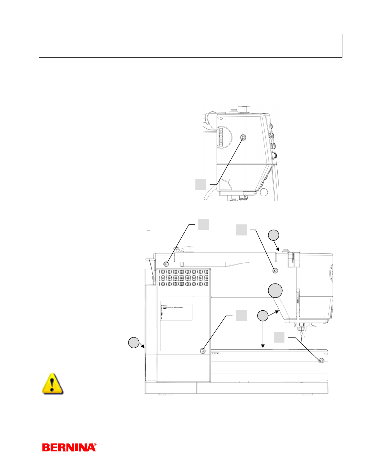
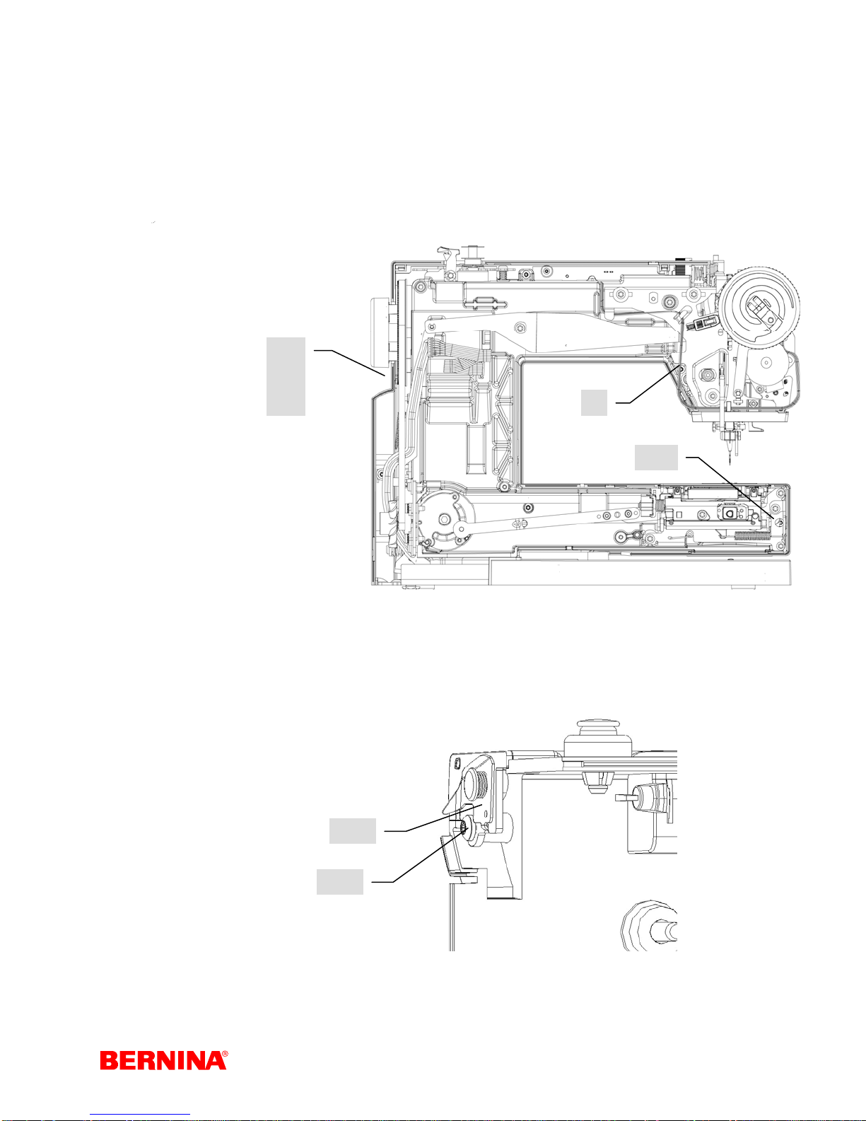
4.1 Removing covers
Before making adjustments, the covers must be removed in the following order:
Head cover:
1. Remove screw (5).
2. Remove head cover.
Attention! The a-640 must have the head cover
refitted when sewing-off.
5
Rear cover:
1. Remove screw (6).
2. Remove screws (7)
(3 screws).
Remove L-Print
cable.
3. Remove rear cover.
4. The covers are linked
with clips
at the points (B).
Slightly press
against the points to
‘de-clip’ them.
Note:
Be sure not to squash the CFL and buttonhole sensor cables in the head area (A) when refitting the covers.
B
7
7
6
B
A
B
B
7
Service-Manual_artista_630_640_english_V4.01_032069_50_04.doc 20
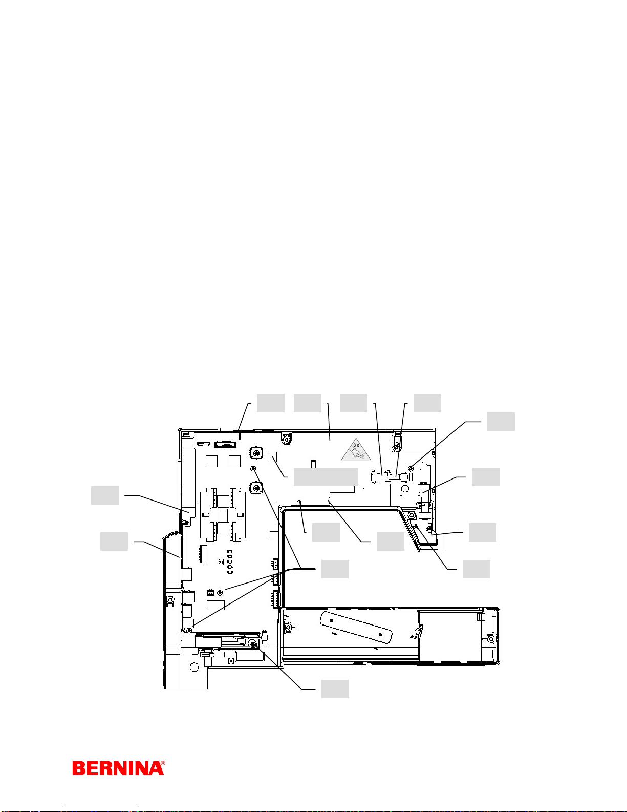
Front cover:
8
1. Remove hook cover.
2. Remove screws (8) (5 screws).
3. Feed-dog drop button must be in sewing position.
4. Turn hand wheel until screw (8a) is accessible (hook drive crank at rear stop).
5. Lift cover over upper thread tension adjusting disc and pull out.
6.
Disconnect connectors (9-12).
(9) main motor / S-Print
(10) S-Print voltage supply
(11) P-Print / S-Print
(12) CFL / S-Print
9
10
11
12
8
8a
4.2 Thread pre-tensioner
Disassembly:
1. Remove rear cover.
2. Remove screw (123).
3. Remove thread pre-tensioner (124) and replace.
Assembly:
1. Refit thread pre-tensioner (124).
2. Refit screw (123).
3. Refit cover.
4. Carry out a functional check.
5. Sew-off
124
123
Service-Manual_artista_630_640_english_V4.01_032069_50_04.doc 21
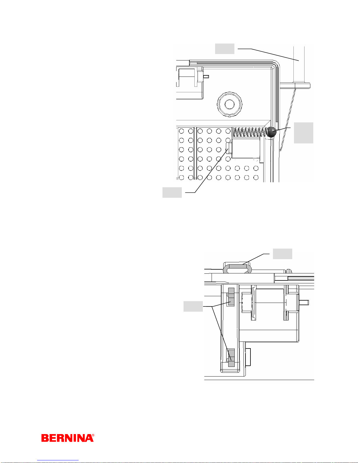
4.3 Vertical spool pin
Disassembly:
1. Remove rear cover.
2. Remove L-Print cover (see p. 27).
3. Push spool pin (125) to the back.
4. Pinch clip (126) and pull spool pin
(125) out to the right. Replace.
Important: Don't lose spring (127) and ball
(128)!
Assembly:
1. Move spool pin (125) to the right in
the guide until clip (126) engages.
Important: Don't forget to refit
2.
spring (127) and ball (128)!
3. Refit L-Print cover.
4. Refit cover. Carry out a functional
check.
5. Sew-off
126
125
127
128
131
4.4 Horizontal spool pin and rear
thread-guide eyelet
Disassembly:
1. Remove rear cover.
2. Pinch clip (129) and
pull spool pin out to the back. Replace.
3. Replace thread-guide eyelet (131).
Assembly:
1. Position thread-guide eyelet (131).
2. Move spool pin forwards in the guide until
clip (129) engages.
3. Refit cover.
4. Carry out a functional check.
5. Sew-off
129
Service-Manual_artista_630_640_english_V4.01_032069_50_04.doc 22
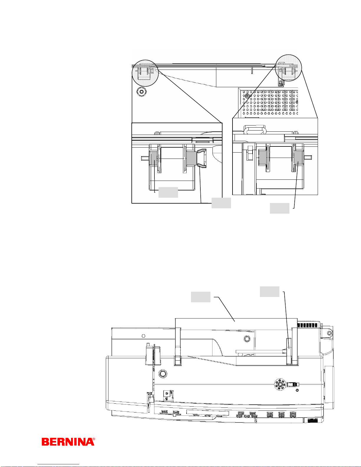
4.5 Carrying handle
Disassembly:
1. Remove rear cover.
2. Remove spool pin (130)
see p. 21.
3. Push pin (132) out to
the left and remove.
4. Carefully prise lock
(133) apart using a
screwdriver. Push pin
(134) out to the right
and remove.
5. Remove handle (135)
and replace.
Assembly:
1. Insert handle (135).
2. Slide pin (134) in from the right until it engages.
3. From the left move pin (132) to the stop.
4. Refit spool pin (130) and thread-guide eyelet (131).
5. Refit cover.
6. Carry out a functional check.
7. Sew-off
134
133
132
130
135
Service-Manual_artista_630_640_english_V4.01_032069_50_04.doc 23
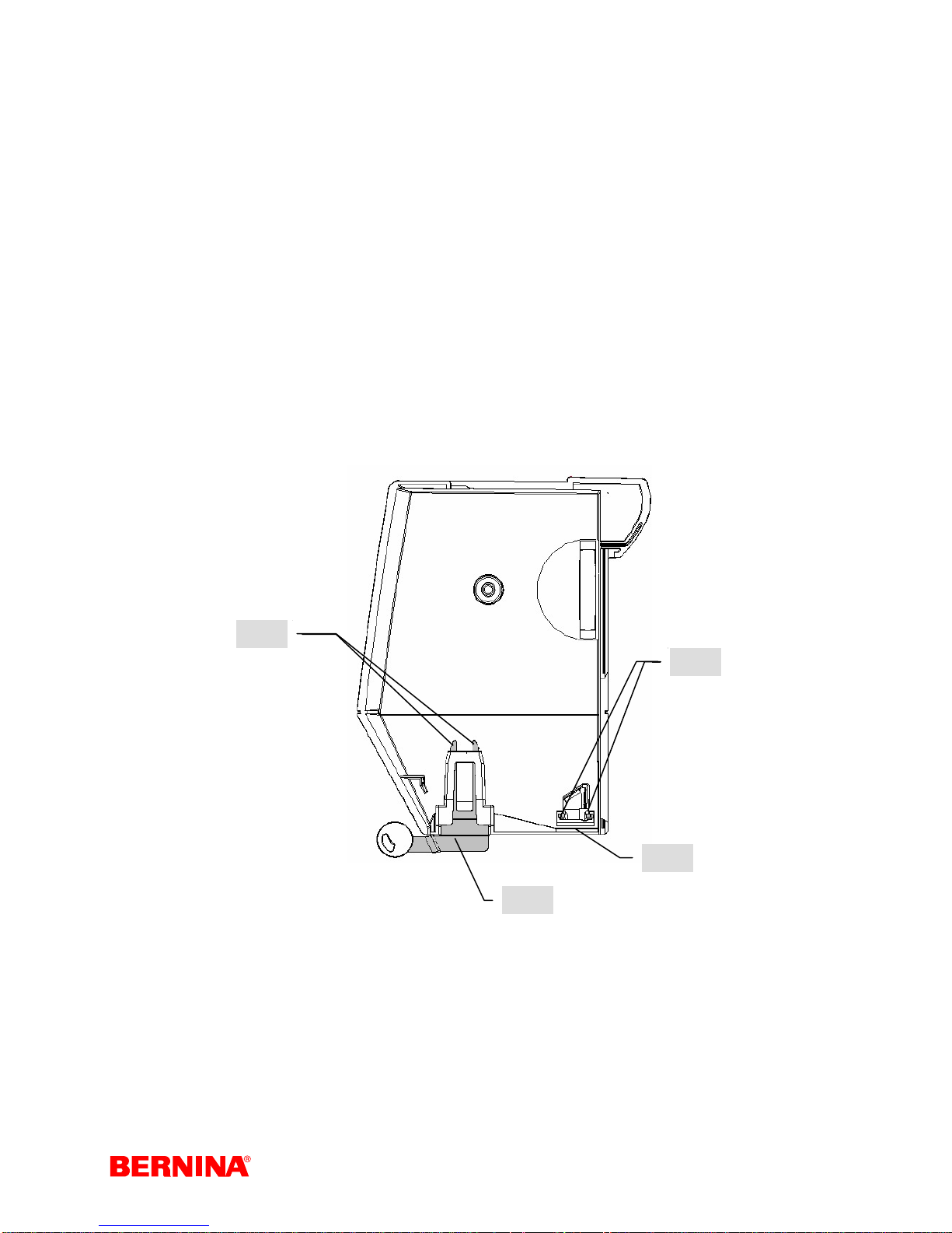
4.6 Magnifying-glass holder and thread cutter
Disassembly:
1. Remove head cover.
2. Pinch clip (136) and pull magnifying-glass holder (137)
downwards and out. Replace.
3. Pinch clip (138) and pull thread cutter (139) downwards
and out. Replace.
Assembly:
1. Move thread cutter (139) upwards in the guide until clip (138) engages.
2. Move magnifying-glass holder (137) upwards in the guide until clip (136) engages.
3. Refit head cover.
4. Carry out a functional check.
5. Sew-off
136
138
137
139
Service-Manual_artista_630_640_english_V4.01_032069_50_04.doc 24
4.7 S-Print, keypads, front panel, RET-Print, touch screen, display and
side cover (plugs)
Disassembly:
1. Remove covers.
2. Pull adjusting button off speed regulator.
3. Remove screw (17).
4. Press clip (19) down and remove side cover (20) to the left.
5. The artista 640 requires disconnection of lower thread indicator cable.
6. Carefully slide down the locking clip to disconnect and remove the cables (21) from S-Print (22) and
RET-Print (23).
7. Remove screw (13) from RET-Print.
8. Remove RET-Print (23).
9. Carefully slide down the locking clip to disconnect the ribbon cable (25) from the touch screen.
10. Carefully slide down the locking clip to disconnect the ribbon cable (24) from the LCD.
11. Disconnect LCD backlighting plug (27). Note: Pull only on the plug, and not the LCD lighting cable,
because the CFL tube may break.
12. Remove screws (16) – 4 screws.
13. To remove, lift S-Print (22) from beneath and pull out from under pin (14).
14. Guide plug (27) out through opening (26).
15. Use the special tool (IC extractor) to remove EEPROM from old S-Print. Transfer it directly to new SPrint. NOTE: Take care to place EEPROM in the correct position and avoid bending the contacts.
16. Remove screws (15) – 4 screws – from bridges (18). Remove LCD and touch screen. Replace (p. 24)
17. Remove keypad (4).
18. Remove the five front cover clips (3), remove the front panel and replace.
2214
24 25
16
EEPROM
19
20
Service-Manual_artista_630_640_english_V4.01_032069_50_04.doc 25
26
27
16 13
17
21
23
3
15
4
3
18
Markings must match!
Assembly:
S-Print, keypad, front panel, RET-Print, touch screen, LCD and side cover (plugs)
1. Slide front panel (4) into guides until front panel clips (3) engage.
2. Insert touch screen into opening – check for dirt before.
3. Insert LCD. Position bridges (18) and fasten with screws (15).
4. Insert keypad (4) – contacts must not be dirty or oily!
5. Insert S-Print (22) and LCD backlighting cable (27) into opening (26). Carefully draw ribbon cables (24
and 25) through the opening.
6. Make sure to insert the shaft faces of the stitch width and stitch length adjusting knobs into the
respective SW/SL potentiometer openings on the S-Print.
7. Tighten screws (16) to fasten S-Print.
8. Reconnect cables (21, 24, 25, 27) and lower thread indicator on artista 640. Make sure that the ribbon
cables sits correctly, and carefully close the locking clip.
9. Refit front cover. Feed-dog switch must be active (in the sewing mode).
10. It is essential to calibrate the maximum speed, the balance and the buttonhole in the service program
before these values can be saved on the S-Print.
11. Carry out a functional check.
12. Sew-off
Important: Is the EEPROM in place?
Service-Manual_artista_630_640_english_V4.01_032069_50_04.doc 26
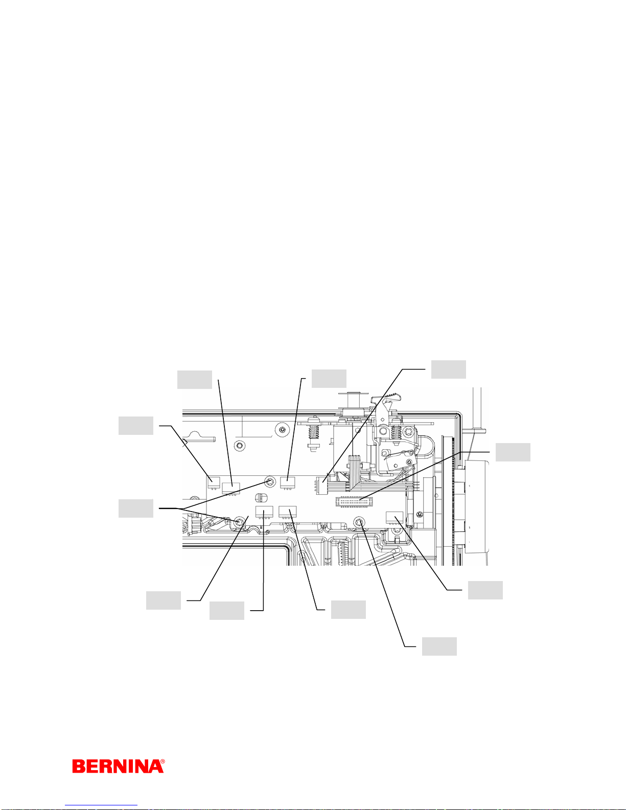
4.8 P-Print
Disassembly:
1. Remove covers.
2. Disconnect plugs (141-148).
3. Remove screws (140).
4. Remove P-Print (149) and replace.
Assembly:
1. Insert P-Print (149).
2. Refit screws (140).
3. Required lateral position of the P-Print (can be seen in the PCB's cut-out) => disc must lie centred in the
light barrier.
4. Reconnect plugs (141-148).
5. Refit covers.
6. Carry out a functional check.
7. Sew-off
Connectors:
141 => presser foot lifter sensor 142 => stitch width stepping motor 143 => presser foot pressure sensor 144 =>
winder motor
145 => S-Print 146 (2 connectors on artista 640’s S-Print) => stitch length stepping motor
147 => buttonhole foot sensor 148 => BSR sensor
142
143
144
141
140
149
148
145
146
147
140
Service-Manual_artista_630_640_english_V4.01_032069_50_04.doc 27
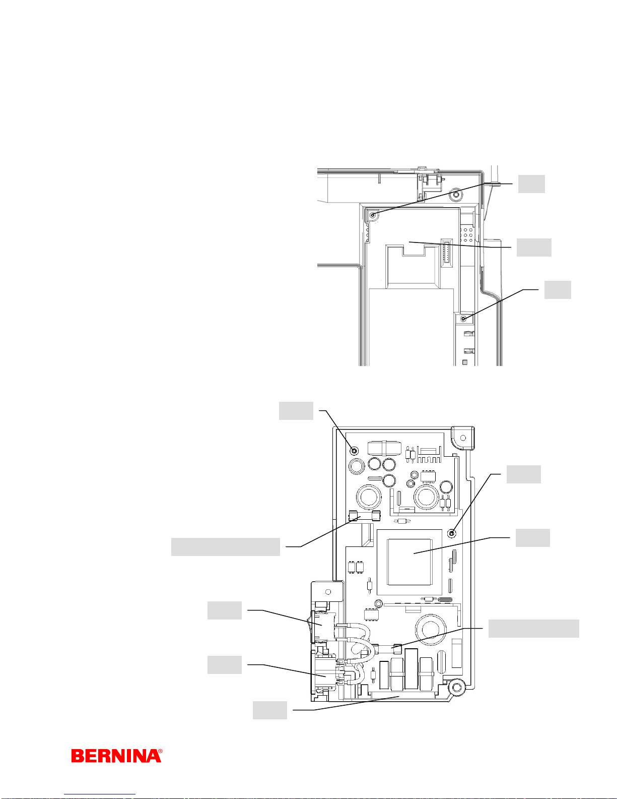
4.9 L-Print
Disassembly:
1. Remove rear cover.
2. Remove screws (18).
3. Remove L-Print cover (103).
4. Check the primary (157) F2 (3.15A 250V) and secondary (153) F3 (4A - 250V) fuses. Replace if
necessary.
5. Disengage switch (156) and socket (155).
6. Remove screws (151).
7. Lift L-Print (152) from top and pull out of
guide (154).
8. Replace L-Print (152).
Assembly:
1. Refit L-Print (152) and screws (151)
- they are shorter than screws (18).
2. Re-engage switch (156) and socket (155).
3. Refit L-Print cover (103).
4. Refit screws (18) and covers.
5. Calibrate speed.
6. Carry out a functional check.
7. Sew-off
18
103
18
Fuse F 2 T- 3,15 A
Item number
031 999.50.00
Fuse F 3 T- 4 A
Item number
031 999.50.01
151
151
152
157 / 3.15A – 250V
156
153 / 4A –250 V
155
Service-Manual_artista_630_640_english_V4.01_032069_50_04.doc 28
154
4.10 CFL
Disassembly:
1. Remove covers.
2. Remove screw (159).
3. Disengage CFL (160) from both fastening
clips (168). Replace.
Note:
The presser foot bar must be down!
Do not bend CFL tube!
Assembly:
1. Refit CFL light (160).
2. Place cable (157) into guide (158).
Important: Be sure not to squash the
cables.
3. Refit CFL – the two clips must engage.
4. Refit screws (159) including washers.
5. Refit covers.
6. Carry out a functional check.
7. Sew-off.
Note:
If a fault in the CFL light or the screens
background lighting occurs, then because of
safety regulations the high voltage power is switched off.
If the screen is not lighting, check the CFL first!
157
161
162
168
160
158
159
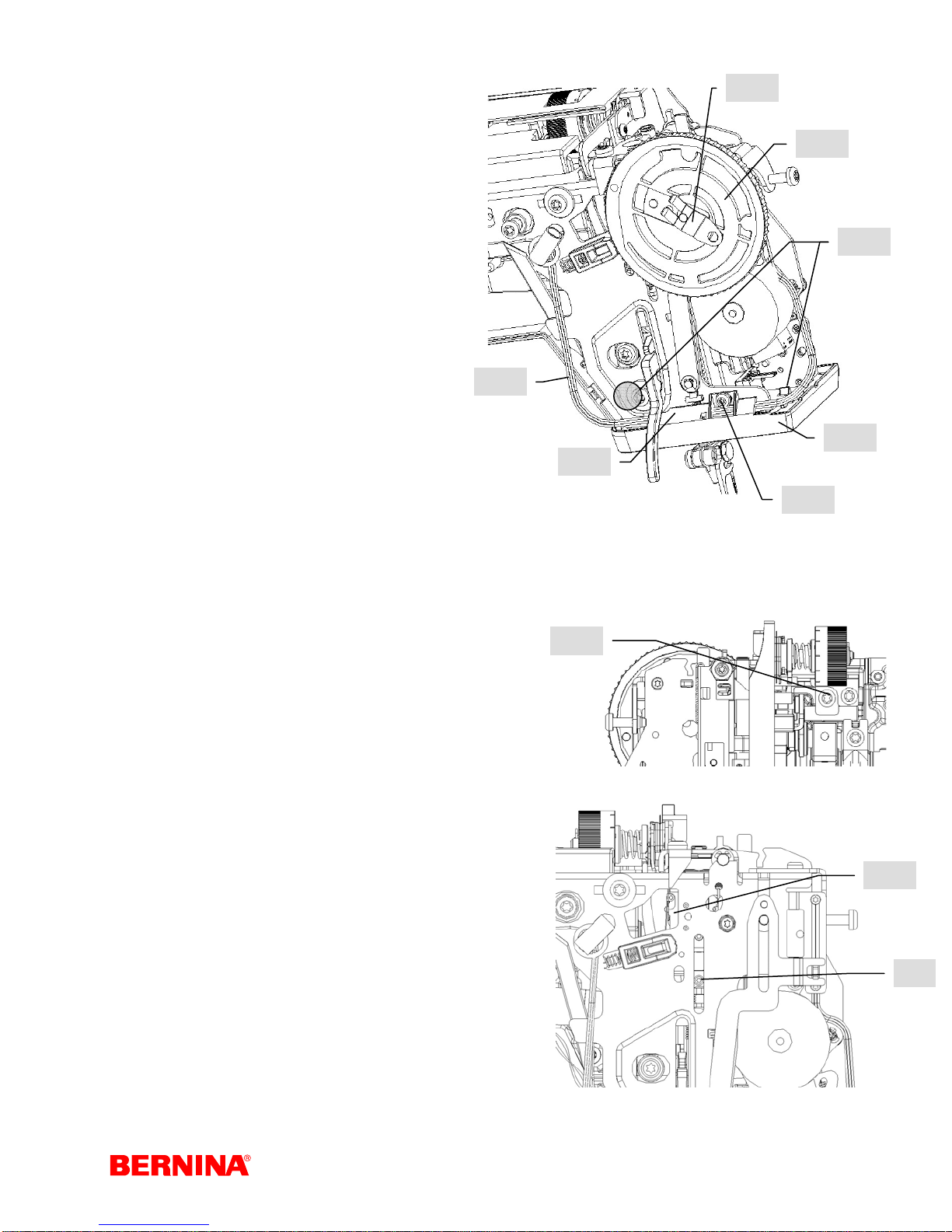
4.11 Presser foot lifter sensor (micro switch)
Disassembly:
1. Remove covers.
2. Remove adjusting wheel lock (161).
3. Remove carefully the adjusting wheel (162) so
that the spring loaded pressure lever remains in
place.
4. Remove upper thread tension (p. 40/41).
5. Disconnect plug (141) from P-Print (149), see page 26,
and unthread cable from guide.
6. Loosen link shaft screw (163), then remove, including
clamp.
7. Use thread take-up lever to swing link shaft down.
8. Loosen screw (88), then swing hopper mechanism
lever downwards to front.
9. Remove the 2 screws (165) from micro switch and
holder.
10. Slide micro switch including cable out to front.
163
165
88
Service-Manual_artista_630_640_english_V4.01_032069_50_04.doc 29
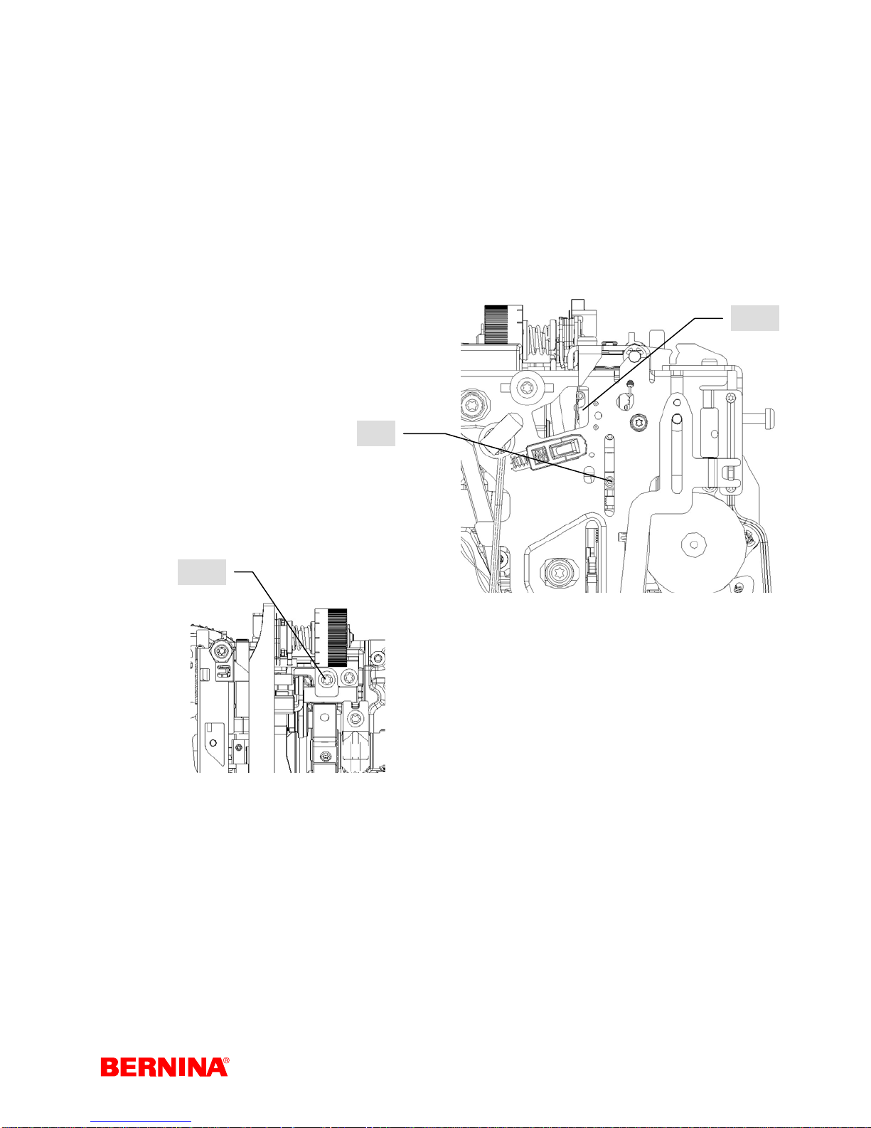
Assembly:
1. Refit micro switch (165). Fitting position => the bores of the switch must be placed accurately to the lugs
in the head frame. If the switch is at an angle when the screw is tightened, the switch may be damaged.
2. Draw cables through rear opening and place into cable guides.
3. Connect plug (141) to P-Print (149).
4. Turn hopper mechanism lever into position, then tighten screw (88) slightly.
5. Use thread-take up lever to swing link shaft up. Then refit clamp with screw (163). To clear the thread
take-up’s play, push link shaft slightly to the right.
6. Refit upper thread tension (p. 40/41).
7. Set darning foot height. (p. 46)
8. Refit adjusting wheel (162) and safety stop (161). Make sure the pressure lever fits into the spring, into
the potentiometer and the guide of the adjusting wheel.
9. Refit covers.
10. Carry out a functional check
11. Sewing-off.
163
88
165
Service-Manual_artista_630_640_english_V4.01_032069_50_04.doc 30
 Loading...