

FRITSCH ANALYSETTE 3 PRO User Manual

Operating instructions
VIBRATORY SIEVE SHAKER
ANALYSETTE 3
Valid starting with: 03.X020/2019
Read the instructions prior to performing any task!
Translation of the original operating instructions

Fritsch GmbH
Milling and Sizing
Industriestraße 8
D - 55743 Idar-Oberstein
Telephone: +49 (0)6784/ 70-0
Fax: +49 (0)6784/ 70-11
email: info@fritsch.de
Internet: www.fritsch.de
Version 11/2014 Index 002

Certifications and CE conformity
Certifications and CE conformity
Certification
CE Conformity
Fritsch GmbH has been certified by the TÜV-Zertifizierungsgemeinschaft
e.V.
An audit certified that Fritsch GmbH conforms to the requirements of
the DIN EN ISO 9001:2008.
The enclosed Conformity Declaration lists the guidelines the FRITSCH
instrument conforms to, to be able to bear the CE mark.
- 3 -

Table of contents
Table of contents
Basic structure............................................................................... 7
1
2 Safety information and use........................................................... 9
2.1 Requirements for the user..................................................... 9
2.2 Scope of application............................................................... 9
2.2.1 Operating principle........................................................... 10
2.2.2 Amplitude control............................................................. 10
2.3 Obligations of the operator................................................. 11
2.4 Information on hazards and symbols used in this manual.. 11
2.5 Device safety information.................................................... 14
2.6 Protective equipment.......................................................... 15
2.7 Hazardous points................................................................. 16
2.8 Electrical safety.................................................................... 16
2.8.1 General information......................................................... 16
2.8.2 Protection against restart................................................. 16
2.8.3 Overload protection.......................................................... 16
3 Technical data.............................................................................. 17
3.1 Dimensions.......................................................................... 17
3.2 Weight.................................................................................. 17
3.3 Operating noise.................................................................... 17
3.4 Voltage................................................................................. 17
3.5 Current consumption........................................................... 17
3.6 Power consumption............................................................. 17
3.7 Electrical fuses..................................................................... 18
3.8 Load..................................................................................... 18
3.9 Sieve mesh widths that can be used.................................... 18
4 Installation................................................................................... 19
4.1 Transport............................................................................. 19
4.2 Unpacking............................................................................ 19
4.3 Setting up............................................................................. 19
4.4 Ambient conditions.............................................................. 20
4.5 Electrical connection............................................................ 20
4.5.1 Adjusting the mains voltage.............................................. 21
5 Initial start-up.............................................................................. 22
5.1 Switching on......................................................................... 22
5.2 Function check..................................................................... 22
5.3 Switching off........................................................................ 22
6 Using the device........................................................................... 23
6.1 Sieving with the ANALYSETTE 3........................................... 23
6.1.1 Fitting and clamping the sieves......................................... 23
6.1.2 Multiple sieving................................................................. 24
- 4 -

Table of contents
6.1.3 Feed quantity for dry or wet sieving................................. 25
6.2 Dry sieving............................................................................ 25
6.2.1 Sieving parameters........................................................... 25
6.2.2 Sieving aids........................................................................ 26
6.3 Wet sieving.......................................................................... 26
6.3.1 Sieving parameters........................................................... 27
6.3.2 Wetting agents.................................................................. 27
6.3.3 Feeding the rinsing liquid.................................................. 27
6.3.4 Extracting the passing particles........................................ 28
6.3.5 Tips for wet sieving of difficult sieving stock.................... 28
6.4 Micro-precision sieving with the ANALYSETTE 3 PRO.......... 29
6.4.1 Sieving parameters........................................................... 29
6.4.2 Feed quantity.................................................................... 29
6.4.3 Fitting the micro-precision sieves..................................... 29
6.4.4 Wet sieving with micro-precision sieves........................... 30
6.5 Standby................................................................................ 31
6.6 Setting the sieving time....................................................... 31
6.7 Setting the amplitude.......................................................... 32
6.7.1 Displaying the amplitude.................................................. 32
6.8 Interval time......................................................................... 32
6.9 Saving and invoking the settings.......................................... 33
6.10 Micro sieving...................................................................... 33
7 Accessories................................................................................... 34
7.1 AUTOSIEVE program............................................................ 34
7.2 Connecting the PRO sieve shaker to the serial interface..... 34
7.3 Sound absorption hood....................................................... 34
7.4 TorqueMaster...................................................................... 35
7.4.1 Fitting the TorqueMaster clamping device....................... 35
7.4.2 Clamping the TorqueMaster............................................. 36
7.4.3 Releasing the TorqueMaster............................................. 37
7.4.4 TorqueMaster malfunctions............................................. 38
7.4.5 Compatibility..................................................................... 38
7.5 Conversion to vibratory sieve shaker PULVERISETTE 0........ 38
7.5.1 Conducting a grinding operation...................................... 39
7.5.1.1 Fitting and clamping the mortar.................................... 39
7.5.1.2 Parameters..................................................................... 40
7.5.1.3 Grinding with liquid nitrogen......................................... 40
7.5.1.4 Final fineness of a grinding process with the PULVERI-
SETTE 0........................................................................... 41
7.5.1.5 Cleaning grinding elements........................................... 41
8 Cleaning........................................................................................ 42
8.1 Cleaning the device.............................................................. 42
8.2 Cleaning the test sieves (mesh wire sieves)......................... 42
- 5 -

Table of contents
9 Maintenance................................................................................ 44
9.1 Maintenance of the TorqueMaster clamping device........... 44
10 Repairs......................................................................................... 45
10.1 Checklist for troubleshooting............................................. 45
11 Disposal........................................................................................ 46
Guarantee terms.......................................................................... 47
12
13 Exclusion of liability..................................................................... 49
14 Safety logbook............................................................................. 51
15 Index............................................................................................. 53
- 6 -

1 Basic structure
Basic structure
Fig. 1: ANALYSETTE 3 SPARTAN
1 Plexiglas clamping lid
2 Test sieve
3 Belt clamping device
4 Vibratory plate
- 7 -
5 Knurled knob
6 Toothed belt
7 Sieve pan
8 Control panel SPARTAN

Basic structure
Fig. 2: ANALYSETTE 3 PRO with sieve stack for micro sieving
9 Clamping lid with a nozzle
10 Sieve spacer ring with 2 seals
11 Sieve pan with funnel
12 Clamping ring with fast locking clamp
13 Control panel PRO
- 8 -

2 Safety information and use
Requirements for the user
2.1
This operating manual is intended for persons assigned with operating
and monitoring the Fritsch the ANALYSETTE 3. The operating manual and
especially its safety instructions are to be observed by all persons
working on or with this device. In addition, the applicable rules and regulations for accident prevention at the installation site are to be observed.
Always keep the operating manual at the installation site of the the ANALYSETTE 3.
People with health problems or under the influence of medication,
drugs, alcohol or exhaustion must not operate this device.
The the ANALYSETTE 3 may only be operated by authorised persons and
serviced or repaired by trained specialists. All commissioning, maintenance and repair work may only be carried out by technically qualified
personnel. Qualified personnel are persons who, because of their education, experience and training as well as their knowledge of relevant
standards, regulations, accident prevention guidelines and operating
conditions, are authorised by those responsible for the safety of the
machine to carry out the required work and are able to recognize and
avoid possible hazards as defined for skilled workers in IEC 364.
In order to prevent hazards to users, follow the instructions in this
manual.
Malfunctions that impair the safety of persons, the the ANALYSETTE 3 or
other material property must be rectified immediately. The following
information serves both the personal safety of operating personnel as
well as the safety of the products described and any devices connected
to them: All maintenance and repair work may only be performed by
technically qualified personnel.
Safety information and use
2.2 Scope of application
This operating manual is not a complete technical description. Only the
details required for operation and maintaining usability are described.
Fritsch has prepared and reviewed this operating manual with the
greatest care. However, no guarantee is made for its completeness or
accuracy.
Subject to technical modifications.
The "ANALYSETTE 3 PRO" is a vertical vibrating laboratory sieve shaker
used for the exact separation and classification of grain fractions. Dry
bulk solids as well as particle collectives in suspensions can be analysed.
Depending on feed quantity and grain size, the test sieves and sieve pans
can be clamped with different diameters and heights.
- 9 -

Safety information and use
CAUTION!
The conversion of the "ANALYSETTE 3 PRO" to the micro
mill "PULVERISETTE 0" cannot be recommended, as the
amplitude control is unusable due to the ball collision malfunctions and therefore has no utility value. In this case, the
"ANALYSETTE 3" SPARTAN is more suitable.
However if you are using the PRO version with the PULVERISETTE 0 grinding attachment, note that the amplitude must
not be set to > 2 mm, as otherwise damage will be caused
to the device, for which we accept no responsibility.
The "ANALYSETTE 3 SPARTAN" is equivalent in design to the PRO model,
except that the range of functions is limited. The serial interface, electronic amplitude control, amplitude display, interval time specification,
micro sieving option as well as the standby function are not included.
2.2.1
Operating principle
2.2.2 Amplitude control
The plastic housing contains a solid cast structure with an electronically
controlled electromagnet. Three permanently flexible flat springs carry
the pole plate of this magnet together with the vibratory plate, which is
fastened to it. When the magnet is switched on, the pole plate and vibratory plate are attracted and spring back when it is switched off. The cast
structure and magnet on one side and the pole plate, vibratory plate and
sieves on the other side form a vibratory system.
The different number of sieves and sieving stocks or grinding attachments changes the natural frequency of the vibratory system. For this
reason, it is not always possible to set the amplitude of the sieve shaker
optimally e.g. with a constant 50 Hz mains frequency present. The processor-controlled electronics of the ANALYSETTE 3 PRO sieve shaker
ensures a precisely adjustable, reproducible sieve amplitude. This is achieved by bringing the frequency to stimulate oscillation closer to the natural frequency of the system or farther away from it. The desired oscillation amplitude of the sieve stack between 0.1 mm and 3.0 mm can
always be achieved - and with relatively low energy input. Therefore,
continuous operation is possible without heating the sample material
and the overall sieve system.
An electronic control circuit guides the sieve frequency of the ANALYSETTE 3 PRO from a high to a low frequency range. In the meantime, a
measuring system records the amplitude and reports it to the control circuit until the preselected amplitude is reached.
This amplitude control takes place at regular intervals during the entire
operation. This makes it possible to react to changes in the sieve system.
- 10 -

Obligations of the operator
2.3
Safety information and use
The amplitude of the ANALYSETTE 3 SPARTAN is set manually with the
Plus and Minus key on the control panel and viewed on the lid.
Before using the the ANALYSETTE 3, this manual is to be carefully read
and understood. The use of the the ANALYSETTE 3 requires technical
knowledge; only commercial use is permitted.
The operating personnel must be familiar with the content of the operating manual. For this reason, it is very important that these persons
actually receive the present operating manual. Ensure that the operating
manual is always near the device.
The the ANALYSETTE 3 may exclusively be used within the scope of applications set down in this manual and within the framework of guidelines
put forth in this manual. In case of non-compliance or improper use, the
customer assumes full liability for the functional capability of the ANALYSETTE 3 and for any damage or injury arising from failure to fulfil this
obligation.
By using the the ANALYSETTE 3 the customer agrees with this and recognizes that defects, malfunctions or errors cannot be completely
excluded. To prevent risk of damage to persons or property or of other
direct or indirect damage, resulting from this or other causes, the customer must implement sufficient and comprehensive safety measures
for working with the the ANALYSETTE 3.
Neither compliance with this manual nor the conditions and methods
used during installation, operation, use and maintenance of the the ANALYSETTE 3 can be monitored by Fritsch GmbH. Improper execution of the
installation can result in property damage and thus endanger persons.
Therefore, we assume absolutely no responsibility or liability for loss,
damage or costs that result from errors at installation, improper operation or improper use or improper maintenance or are in any way connected to these.
The applicable accident prevention guidelines must be complied with.
Generally applicable legal and other obligatory regulations regarding
environmental protection must be observed.
2.4 Information on hazards and symbols used in this manual
Safety information
- 11 -
Safety information in this manual is designated by symbols. Safety information is introduced by keywords that express the extent of the hazard.
DANGER!
This symbol and keyword combination points out a directly
hazardous situation that can result in death or serious
injury if not avoided.
Safety information and use
WARNING!
This symbol and keyword combination points out a possibly
hazardous situation that can result in death or serious
injury if not avoided.
CAUTION!
This symbol and keyword combination points out a possibly
hazardous situation that can result in slight or minor injury
if not avoided.
NOTICE!
This symbol and keyword combination points out a possibly
hazardous situation that can result in property damage if
not avoided.
Special safety information
ENVIRONMENT!
This symbol and keyword combination points out a possibly
hazardous situation that can result in environmental
damage if not avoided.
To call attention to specific hazards, the following symbols are used in
the safety information:
DANGER!
This symbol and keyword combination points out a directly
hazardous situation due to electrical current. Ignoring information with this designation will result in serious or fatal
injury.
DANGER!
This symbol and keyword combination designates contents
and instructions for proper use of the machine in explosive
areas or with explosive substances. Ignoring information
with this designation will result in serious or fatal injury.
- 12 -
Safety information and use
DANGER!
This symbol and keyword combination designates contents
and instructions for proper use of the machine with combustible substances. Ignoring information with this designation will result in serious or fatal injury.
WARNING!
This symbol and keyword combination points out a directly
hazardous situation due to movable parts. Ignoring information with this designation can result in hand injuries.
WARNING!
This symbol and keyword combination points out a directly
hazardous situation due to hot surfaces. Ignoring information with this designation can result in serious burn injuries
due to skin contact with hot surfaces.
Safety information in the procedure
instructions
Tips and recommendations
Safety information can refer to specific, individual procedure instructions. Such safety information is embedded in the procedure instructions
so that the text can be read without interruption as the procedure is
being carried out. The keywords described above are used.
Example:
1. Loosen screw.
2.
CAUTION!
Risk of entrapment at the lid.
Close the lid carefully.
3. Tighten screw.
This symbol emphasises useful tips and recommendations
as wells as information for efficient operation without mal‐
function.
- 13 -
Safety information and use
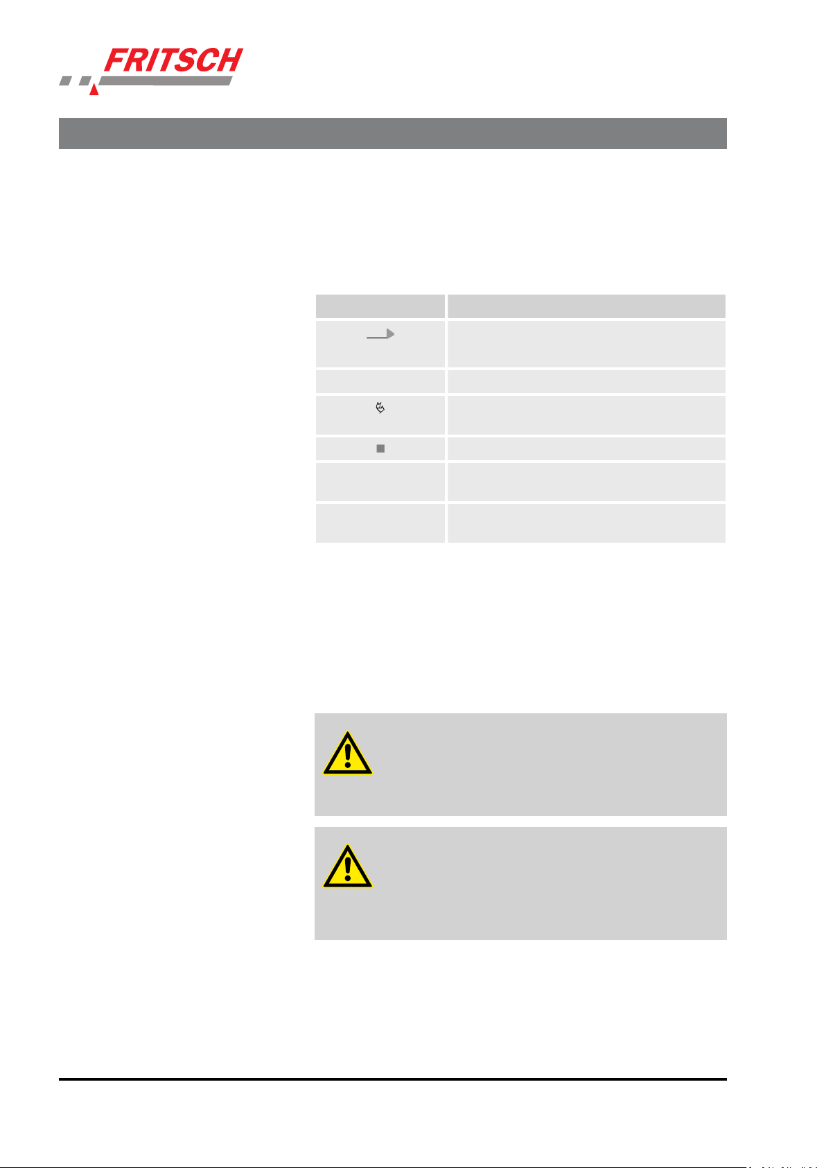
Further designations
To emphasise procedure instructions, results, lists, references and other
elements, the following designations are used in this manual:
Designation Explanation
Step-by-step procedure instructions
1., 2., 3. ...
2.5 Device safety information
Please observe!
ð
[Button] Operating elements (e.g. push button, switch),
‘Display’ Screen elements (e.g. buttons, function key
n Only use original accessories and original spare parts. Failure to
observe this instruction can compromise the safety of the machine.
n Accident-proof conduct is to be strictly followed during all work.
n Comply with all currently applicable national and international acci-
dent prevention guidelines.
CAUTION!
Wear hearing protection!
If a noise level of 85 dB(A) is reached or exceeded, ear protection should be worn to prevent hearing damage.
Results of steps in the procedure
References to sections in this manual and relevant documentation
Lists without a specific order
display elements (
assignment)
e.g. signal lamps)
WARNING!
The maximum accepted concentration (MAC) levels of the
relevant safety guidelines must be observed; if necessary,
ventilation must be provided or the machine must be operated under an extractor hood.
- 14 -

Safety information and use
DANGER!
Explosion hazard!
– When Sieving oxidizable substances, e.g. metals or coal,
there is a risk of spontaneous combustion (dust explosion) if the share of fine particles exceeds a certain percentage. When Sieving these kinds of substances, special safety measures must be taken and the work must
be supervised from a specialist.
The high-speed rotor mill is not explosion protected
–
and is not designed to sieve explosive materials.
n Do not remove the information signs.
NOTICE!
Immediately replace damaged or illegible information signs.
2.6 Protective equipment
n Unauthorised alteration of the the ANALYSETTE 3 will void Fritsch's
declaration of conformity to European directives and void the guarantee.
n Only use the the ANALYSETTE 3 when it is in proper working order,
as intended and in a safety- and hazard-conscious manner adhering
to the operating manual. In particular, immediately rectify any malfunctions that could pose a safety hazard.
n If, after reading the operating manual, there are still questions or
problems, please do not hesitate to contact our specialised personnel.
Protective equipment is to be used as intended and may not
be disabled or removed.
All protective equipment is to be regularly checked for
integrity and proper functioning.
NOTICE!
– The toothed belts must only be released or clamped in
the switched off state.
Before switching on again, ensure that the two toothed
–
belts are evenly, tightly clamped using the knurled
knobs.
- 15 -

Safety information and use
2.7 Hazardous points
2.8 Electrical safety
n Crushing hazard at the sieve tensioning system
n Crushing hazard between vibratory plate and housing
2.8.1
General information
2.8.2 Protection against restart
2.8.3 Overload protection
The main switch separates the device from the mains on two poles.
After switching off at the main switch and switching on again, the START
key must be pressed for start-up.
The mains fuse provides overload protection.
- 16 -

3 Technical data
Dimensions
3.1
3.2 Weight
3.3 Operating noise
Technical data
Without sieve set:
350 x 200 x 400 mm (width x height x depth)
Net: 21 kg
Gross: approx. 27 kg
Emissions value of workplace according to DIN EN ISO 3746:2005 is up to
76.6 dB (A) for sieving gravel. The value fluctuates, depending on fre-
quency, grinding stock and use of sieving aids.
When grinding with the PULVERISETTE 0, the operating noise is greatly
reduced by using the sound absorption hood made of plexiglas (order
no.: 00.0130.17).
3.4 Voltage
3.5 Current consumption
3.6 Power consumption
The device can be operated in two voltage ranges:
n Single phase alternating current 115V ± 10% and
n Single phase alternating current 230 V ± 10%.
Ä
(See also
It is not necessary to change the voltage range manually.
Depending on the mains voltage, the maximum current consumption is
in the ranges:
n 115 V ® 0.44 A
n 230 V ® 0.22 A
Depending on the voltage range, the maximum power consumption is
approx. 50 W.
Chapter 4.5 ‘Electrical connection’ on page 20)
- 17 -
 Loading...