

Page 1
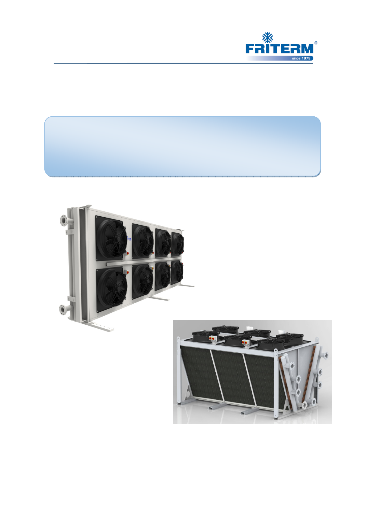
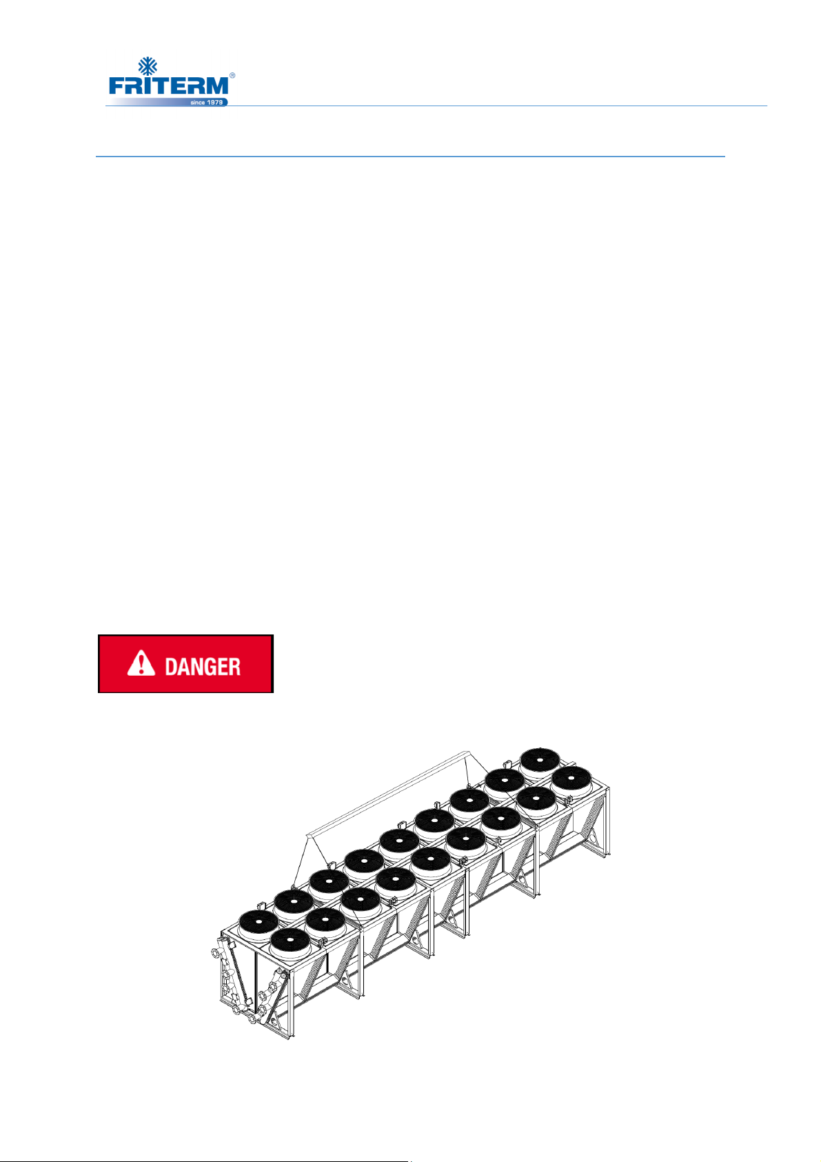
Dry Coolers
INSTALLATION, OPERATION AND
INSTALLATION, OPERATION AND
INSTALLATION, OPERATION AND INSTALLATION, OPERATION AND
MAINTENANCE INSTRUCTIONS
MAINTENANCE INSTRUCTIONS
MAINTENANCE INSTRUCTIONSMAINTENANCE INSTRUCTIONS
FDH, FDV, FDW
www.friterm.com
Page 2

ii
CONTENTS
1. ABOUT THIS MANUAL/GENERAL ............................................................................................ 1
1.1 Examining the operating manual ................................................................................................... 1
1.2 Warranty ........................................................................................................................................ 1
2. SAFETY REGULATIONS .............................................................................................................. 5
2.1 Symbols and warning signs ........................................................................................................... 5
2.2 Personal protection ........................................................................................................................ 6
2.2.1 Personal protection signs ........................................................................................................ 6
2.3 Warnings ....................................................................................................................................... 8
2.4 Improper use .................................................................................................................................. 9
2.4.1 Hazardous rotating machinery ................................................................................................ 9
2.4.2 Hazardous voltage .................................................................................................................. 9
2.4.3 Hazardous thermal .................................................................................................................. 9
2.4.4 Hazardous refrigerant ........................................................................................................... 10
2.5 Environmental protection ............................................................................................................ 11
3. LABELLING ................................................................................................................................... 11
3.1 Product code ................................................................................................................................ 11
3.2 Type plate .................................................................................................................................... 11
3.3 Friterm Logo................................................................................................................................ 12
4. TECHNICAL DATA ...................................................................................................................... 12
4.1 Standards ..................................................................................................................................... 12
4.2 Product ........................................................................................................................................ 12
4.3 Fans ............................................................................................................................................. 13
4.3.1 Fan connection diagrams ...................................................................................................... 14
4.4 Control Systems .......................................................................................................................... 16
4.4.1 Thermostat (Dixell XC650C) Keyboard .............................................................................. 16
4.4.2 Icons ..................................................................................................................................... 17
4.4.3 Parameters ............................................................................................................................ 18
4.4.4 Tables of Alarms .................................................................................................................. 21
4.4.5 Wiring Connection: .............................................................................................................. 22
4.4.6 The Adjustment of Thermostat Control Part According to the Application of Different
Fan Number ................................................................................................................................... 23
4.4.7 Power Wiring ....................................................................................................................... 24
4.4.8 Control Wiring ..................................................................................................................... 25
4.5 Sound pressure level .................................................................................................................... 26
Rev. Tarihi:25.05.2016 Rev.No:9 Dok. No: KLV.004.ENG
Page 3

iii
4.6 Sound power level ....................................................................................................................... 26
5. TRANSPORT AND STORAGE ................................................................................................... 27
5.1 Check for completeness and transport damage ........................................................................... 27
5.2 Transport ..................................................................................................................................... 27
5.3 Storage ......................................................................................................................................... 30
6. INSTALLATION ............................................................................................................................ 30
6.1 Location ....................................................................................................................................... 31
6.2 Requirements at the set up point ................................................................................................. 31
6.2.1 Outdoor set up of FCH unit .................................................................................................. 31
6.2.2 Set up next to wall ................................................................................................................ 31
6.2.3 Set up in pit-hallow .............................................................................................................. 32
6.2.4 Several FDH units ................................................................................................................ 33
6.2.5 Requirements at the set up point (FDW units) ..................................................................... 33
6.2.6 Several FDW units ............................................................................................................... 34
6.2.7 Requirements at the set up point (FDV units) ...................................................................... 34
6.2.8 Side-by-side setup (FDV units) ............................................................................................ 35
6.3 Mounting ..................................................................................................................................... 35
6.3.1 Ideal mounting scheme ......................................................................................................... 38
6.3.2 Leg mounting ....................................................................................................................... 38
6.4 Electrical Connection .................................................................................................................. 51
7. OPERATION .................................................................................................................................. 52
7.1 Initial commissioning .................................................................................................................. 52
7.2 Regular commissioning ............................................................................................................... 52
7.3 Shutting down.............................................................................................................................. 53
7.4 Step control application (If Applicable) ...................................................................................... 53
8. MAINTENANCE ........................................................................................................................... 54
8.1 Maintenance intervals .................................................................................................................. 54
8.2 Fan motor maintenance ............................................................................................................... 55
8.3 Periodical controls (Once a year) ................................................................................................ 56
9. TROUBLESHOOTING .................................................................................................................. 57
Rev. Tarihi:25.05.2016 Rev.No:9 Dok. No: KLV.004.ENG
Page 4

1
1. ABOUT THIS MANUAL/GENERAL
This document specifies the instructions for installation, operating and maintenance of the
Dry Coolers (FDH, FDV, FDW models) manufactured by FRITERM A.Ş., Turkey.
The instructions below must be followed strictly for the labor health and safety reasons during
installation and maintenance of products.
Upon receipt, the product should be visually inspected, and in case of any damage or fault, the
supplier must be notified within 7 days.
The manufacturer will not accept any responsibility in these situations;
• Damages caused by persons,
• Damages product due to the disregarding of the recommendations indicated in this
handbook.
1.1 Examining the operating manual
To follow the instructions defined in this document is a prerequisite for safety of the staff and
for the products to be operated in a fault-free and safe manner.
• The operating manual must always be available.
• All persons who are responsible for the transport, assembly, initial commissioning,
operating, maintenance or repair of the component must be acquainted with the operating
manual. The operator should accept in written form that they are acquainted with the
operating manual.
• Whenever you have difficulty in understanding and/or comprehend and description or
definition given/expressed in this manual, please immediately ask for help from an
expert or from then manufacturer. It is of great importance to understand this manual
completely and correctly for the sake of labor health and safety.
1.2 Responsibilities
The manufacturer is strictly responsible for supplying a manual accompanying the product
which comprises the necessary and enough detailed information regarding the
Rev. Tarihi:25.05.2016 Rev.No:9 Dok. No: KLV.004.ENG
1.2.1 Manufacturer’s Responsibilities
Page 5

2
installation/mounting and operation of the product. Besides, the product is expected to fulfill
the requirements and satisfy with the anticipated functioning.
The construction of the product should comply with the presumed operational conditions. The
product is expected to be robust enough and resistive against all the mechanical, thermal
and
chemical challenges. The material used to produce should be compatible with the fluid and
the mixture of fluids used as heat transfer media.
All the materials and components used in constructing the product should be resistive against
all the stress and pressure that the product will be subjected to.
1.2.2 Contractor’s Responsibilities (Installation, Commissioning)
• Should follow all the instructions and provide all the conditions stated in this manual.
• All the documentation accompanying the product are complementary to this manual. The
safety instructions and all other information stated in this manual should be considered.
• The national regulations regarding the protection of environment and labor safety should
be strictly followed besides the instructions for safe and correct operation.
• In case of any problem encountered during the installation, FRITERM A.Ş. should be
informed and asked for technical assistance if necessary.
• Emergency instructions and the required infrastructure should be prepared and redy for
use in any case.
• The regular maintenance/servicing periods and instructions should be determined and
defined.
• The additive in order to prevent the freezing of the operating fluid should be feed as
requires and as much as required.
• If storage of the product for a long period is needed, a clean, non-hazardous and low
humidity environment is recommended.
• The fans of the products that are stored horizontally are recommended to be run for 4-5
hours a week. In case of difficulty of running the fans, then they should be covered and
protected from rain and excess humidity.
• In case of storing vertically, it is not recommended to store more than 1 month.
Rev. Tarihi:25.05.2016 Rev.No:9 Dok. No: KLV.004.ENG
Page 6

3
1.2.3 Operator’s or Owner’s Responsibilities (Operation and
Maintenance)
• The director is the responsible person who employs the adequate staff for servicing
• operating and monitoring the system.
• All requirements and instructions in this operating manual must be complied with.
• The documentation of purchased products is a constituent part of this operating manual.
All safety information in this operating manual and all other information must be
observed.
• All relevant regulations concerning accident prevention and environmental protection
must be complied as well as the confirmed technical regulations for safe and proper
working.
• Personal ineligibility. All the work should be conducted by authorized and trained
personnel.
• Any defect/damage/malfunction caused by disregarding the instructions given in this
manual is the responsibility of the operator.
• Any defect/damage/malfunction caused by the misuse of the product is the responsibility
of the operator.
• The product should not be put in operation without the completion of the installation and
commissioning.
• The personnel who is responsible for the operation/servicing/maintenance of the product
should be provided with all the necessary documentation including this manual.
1.3 Warranty
• The manufacturer warrants that the equipment delivered to the client shows no defects
caused by failure of design, material, manufacturing and/or workmanship within the
warranty period.
• The client must notify in written form within 10 days from the receipt of the goods, any
perceptible defects including transport damages. For hidden defects, he must notify and
explain in details the defect in written form within 10 days from observation time.
• Unless otherwise agreed, the warranty period shall be 24 months starting from the date of
delivery.
Rev. Tarihi:25.05.2016 Rev.No:9 Dok. No: KLV.004.ENG
Page 7

4
• The warranty does not cover defects in the product’s operation stemming from a fault in
materials or parts provided by the client, nor shall it cover an installation that has not been
assembled according to the manufacturer’s instructions and according to professional
practice. The products or parts that the costs are not paid to the producer are out of
manufacturer’s warranty.
• The products called “Dry Coolers” mainly used in order to cool the fluid (usually water
but in case of atmospheric conditions below zero degree, antifreezer added solution) to a
desired temperature. The fluid to be cooled down should be transferred to the Dry cooler
via the piping properly installed according to the rules and related instructions. The usage
of the Dry Cooler out of its anticipated functioning is out of the scope of warranty.
• In sub-zero temperatures sufficient antifreeze solution must be added and fluid should be
checked by measuring the freezing temperature on a regular basis. In case of occurring
any damage on the product due to freezing of the fluid, all the fitting actions and materials
used in order to repair the product will be out of manufacturer’s warranty.
• The warranty shall not cover equipment and/or its accessories if they have been modified
by the client without manufacturer’s written consent.
• The warranty clause can only be invoked by the client if the equipment is used normally
and in conformity with its purpose and manufacturer’s instructions.
• The manufacturer’s liability hereunder shall be limited to repair, modify or replace the
parts or equipment that shows defect within the limitation of the items under this article.
• The warranty period of the repaired or modified or replaced parts or equipment shall in no
way extend the warranty period of the original ones.
• The works resulting from the warranty conditions shall be carried out in the
manufacturer’s workshop after the client has sent the defective equipment or parts for
repair or replacement.
• The manufacturer’s responsibility is strictly limited to the obligations as stipulated herein
and it is expressly agreed that he shall not be found to make any other indemnity. In
particular, he shall in no case be liable to compensate loss caused directly or indirectly by
a defect in the equipment delivered.
• The product should be installed and commissioned in accordance with the
national/international regulations and rules.
Rev. Tarihi:25.05.2016 Rev.No:9 Dok. No: KLV.004.ENG
Page 8
5
In case of operational conditions with temperatures below zero the sufficient amount of antifreezer (
• For the fans having thermal protection, the related wiring should be definitely done and it
is considered as contractor’s and/or owners responsibility. Any defect caused by
misconnection of the thermal protection wiring in accordance to the circuit diagrams
given in this manual would be out of manufacturer’s warranty.
• The power supply which the product is supplies should not deviate 10% from the values
given on the label.
DANGER OF FREEZING
e.g.Ethelene Glycol) should be added unless the water will stay in the system at still times. In order
to be able to avoid the danger of freezing a sufficient amount of antifreezer solution should be
added to reach a freezing temperature of 7-10 C below the operation temperature.
2. SAFETY REGULATIONS
2.1 Symbols and warning signs
The following terms and/or symbols are used in the operating manual for particularly
important information.
Safety messages and symbols are quoted at the relevant positions in the operating manual if
there is danger such as death, personal injury and environmental damage. These safety
warnings must be strictly adhered to.
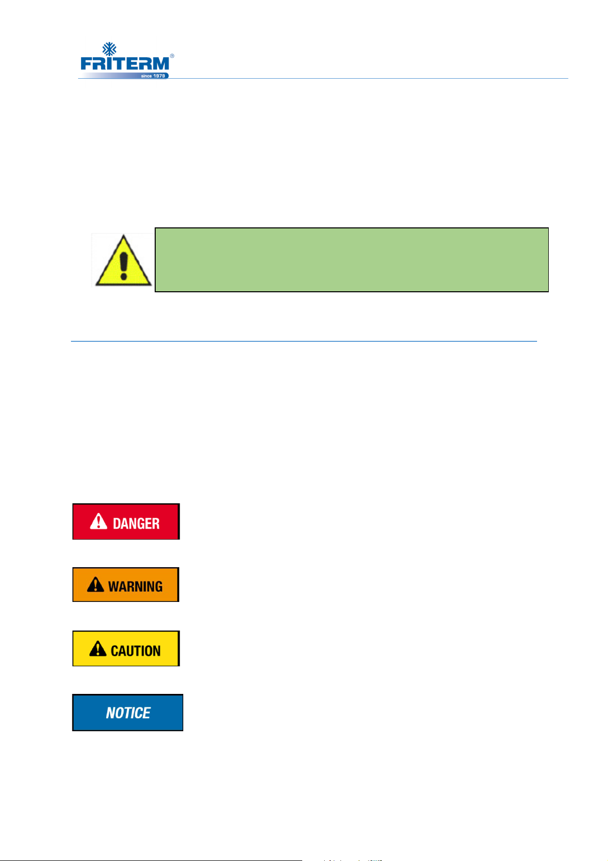
Indicates a hazardous situation which, if not avoided, may
result in death or serious injury
Indicates a hazardous situation which, if not avoided, may result
in serious injury.
Indicates a hazardous situation which, if not avoided, may result
in moderate or minor injury.
Additional notes, information and tips.
Rev. Tarihi:25.05.2016 Rev.No:9 Dok. No: KLV.004.ENG
Page 9
IN CASE OF DANGER
Switch off the power
Switch off the main
Please ask assistance from an authorized technician
Please do not try to resolv
While working on and standing by the
Protective gloves for fitting and repair work
resistant clothing and protective gloves for cleaning work, especially when
Safety goggles for cleaning work, especially
compressed air for cleaning
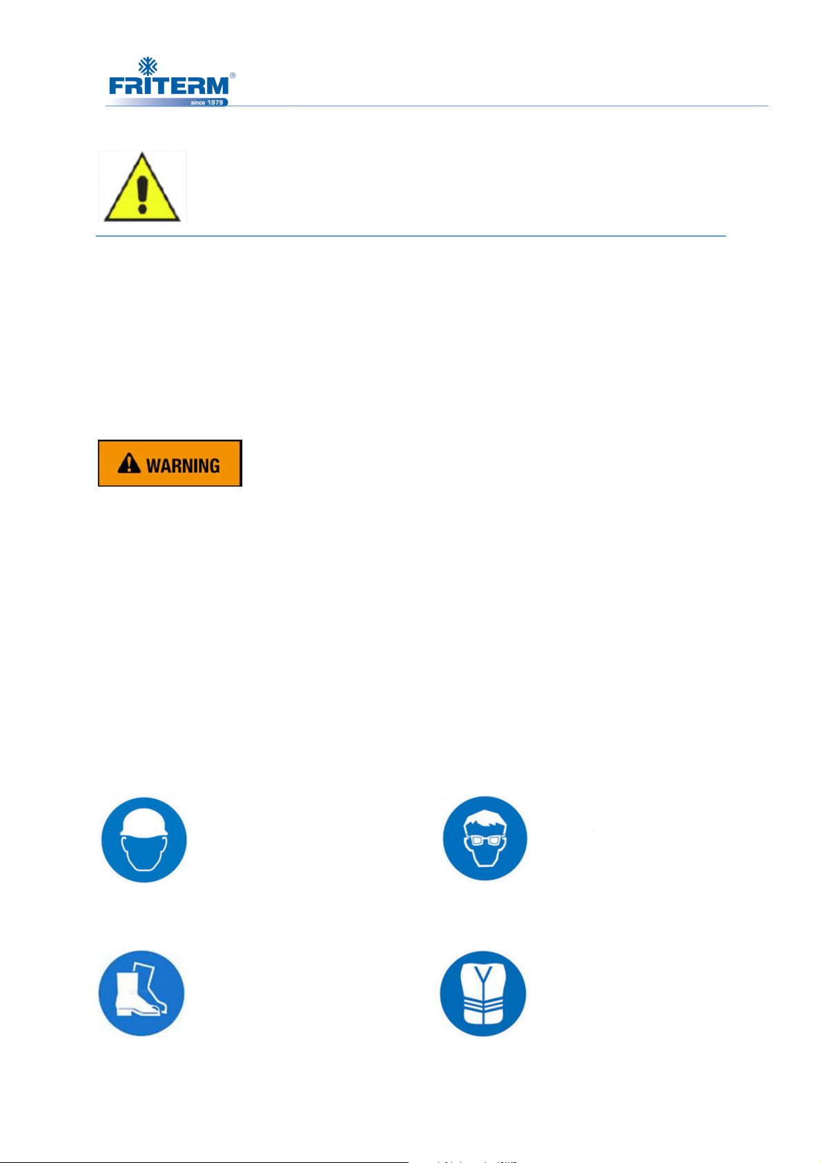
2.2.1 Personal protection signs
Head Protection
Foot Protection
Rev.No:9 Dok. No: KLV.004.ENG
or expert
e any problem by trial and error
, protective clothing must be worn.
handling solvents
Eye Protection
High Visibility Clothing
6
!
•
•
•
•
2.2 Personal protection
• Safety shoes
• Safety helmet
•
• Chemical-
handling solvents
•
.
.
product
while
or using
• Hearing protection
Rev. Tarihi:25.05.2016
Page 10
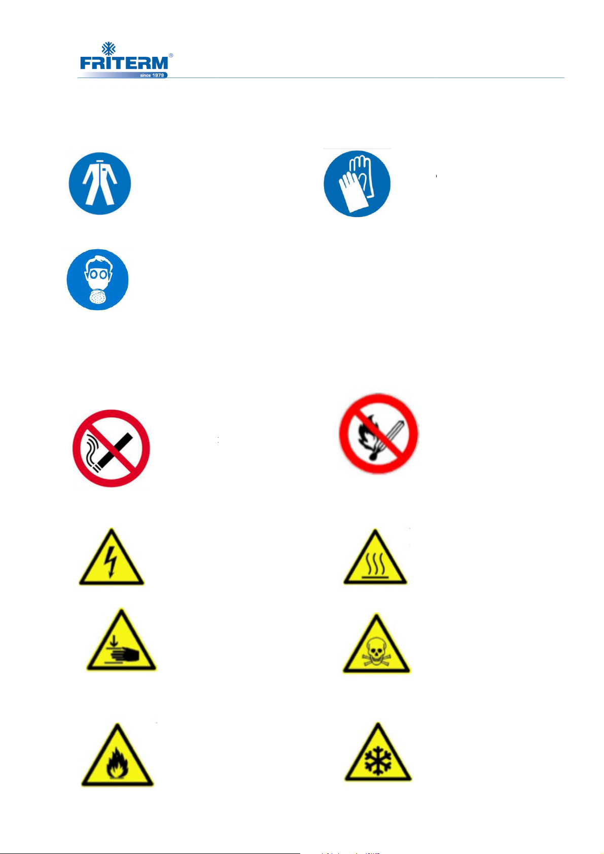
Protective Clothing
Respiratory Protection
No Smoking
High Voltage
Hand Injuries
Fire Risk
Rev.No:9 Dok. No: KLV.004.ENG
Hand Protection
Flammable
Hot Surfaces
Poisoning Danger
Frostbite Hazard
7
2.2.2 Warning signs
Rev. Tarihi:25.05.2016
Page 11
8
2.3 Warnings
• In an unexpected situation use the emergency stop button which is set up on an easily
accessible place.
• Do not exceed maximum operating pressure given on the unit’s type plate.
• Unless the advised safety devices available or fully active the unit must not be
operated.
• Set up the unit with extreme cleanliness.
• The unit must not be operated if it is damaged. FRİTERM A.Ş. must be informed
about all damages.
• The unit must be installed, operated and maintained by authorized/qualified personnel
only.
•
• In case of using any other fluid and additives specified on the label (water, Ethylene
Glycol, propylene Glycol, Brandname thermal fluids) may cause damage, leakage,
danger and environmental pollution.
• No modification is allowed on the product without written permission from the
manufacturer.
• Operational conditions are limited within the specified range by the manufacturer. In
case of need to operate the product out of the range, a confirmation should be asked
from FRITERM A.Ş.
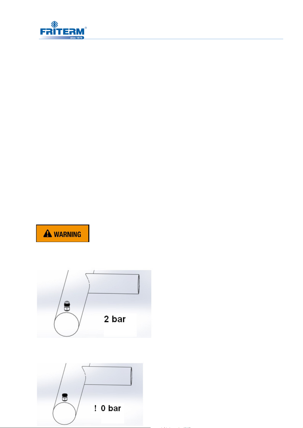
The product is delivered with 2 bar pressure. Upon receipt, it must be checked with
schrader valve.
After checking, unless the product has 2 bar pressure Friterm must be notified
immediately.
Rev. Tarihi:25.05.2016 Rev.No:9 Dok. No: KLV.004.ENG
Page 12
Danger of injuries in improper using;
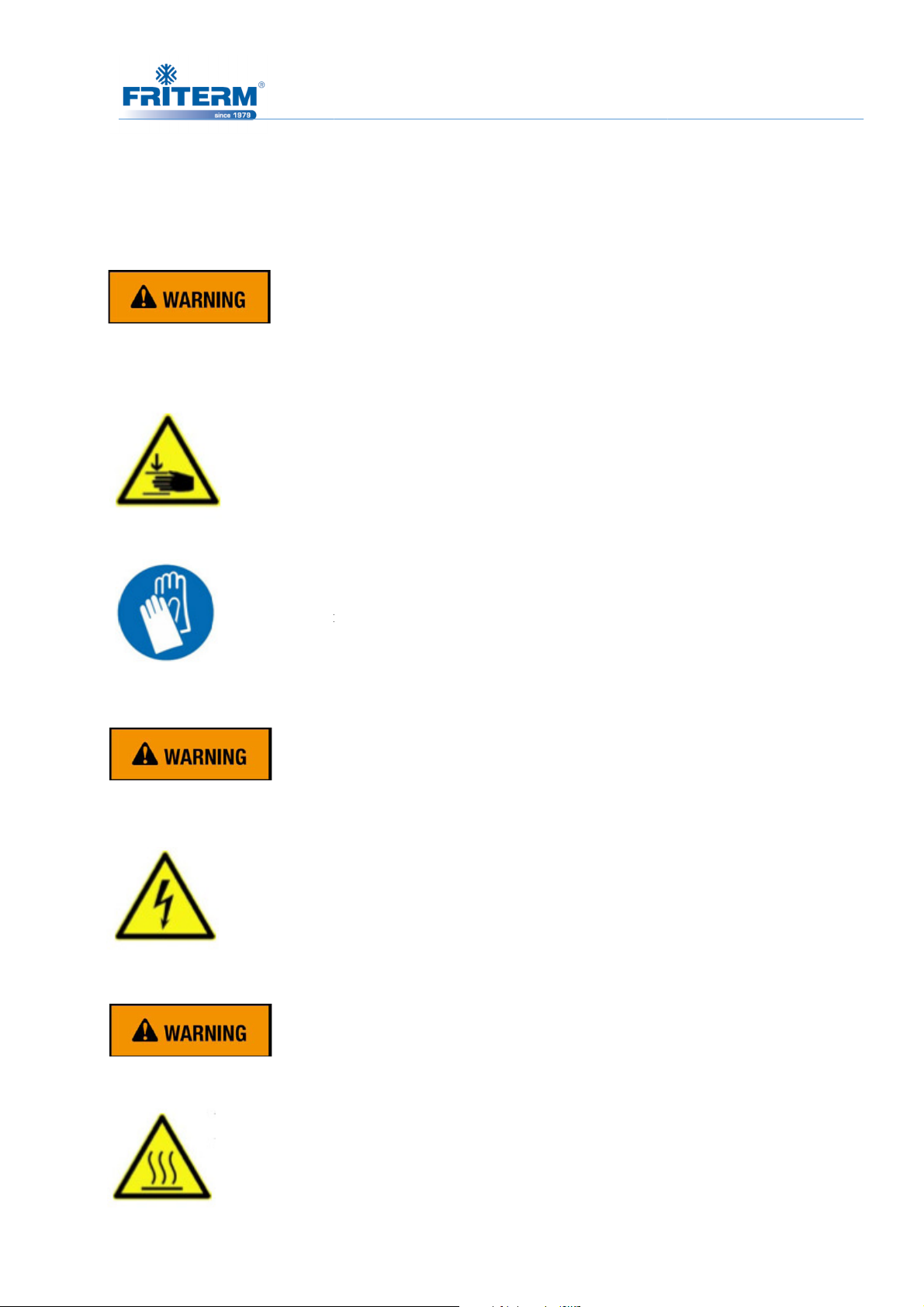
2.4.1 Hazardous rotating machinery
Danger of
authorized technician.
Use hand protection.
oltage can cause serious injuries or death. Do not contact with
voltage direct or indirect. Do not
begin maintenance work.
Some of the components of the unit such as fin and tube have high
Rev.No:9 Dok. No: KLV.004.ENG
Lids should be unscrewed by an
forget to power off the unit before you
2.4 Improper Use
9
2.4.2 Hazardous voltage
Electrical v
cutting hands and fingers.
2.4.3 Hazardous thermal
temperatures.
Rev. Tarihi:25.05.2016
Page 13
Danger of burns and frostbites.
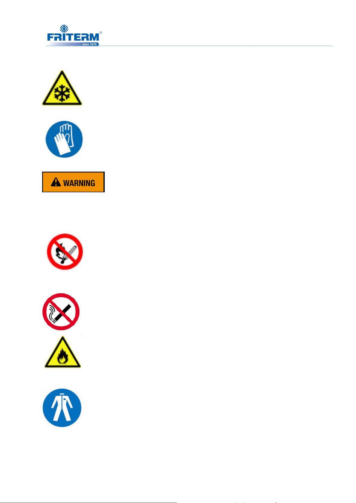
The danger of frostbite can occur if there
if the unit cannot be drained completely, frostbite hazard occurs after
Fluid: Glycol
Yanıcı özelliğinden dolayı etilen glikol her zaman ate
No smoking.
suitable fire
while working with fire or sparks.
Due to the hazardous effect on human skin and nerve system please avoid
direct contact of skin.
Rev.No:9 Dok. No: KLV.004.ENG
ficient frost protection.
o prevent ignition
For protection use protective clothing.
10
is insuf
Also
draining.
2.4.4 Hazardous
Ensure
fighting equipment is used in order t
Rev. Tarihi:25.05.2016
Page 14
11
2.5 Environmental protection
While handling the product, it has to be ensured that materials which can endanger the
environment are disposed of properly. Service materials must not be allowed to enter the
sewerage system and the ground water system.
All relevant national regulations concerning environmental protection and the technical issues
for safe and proper working must be complied.
3. LABELLING
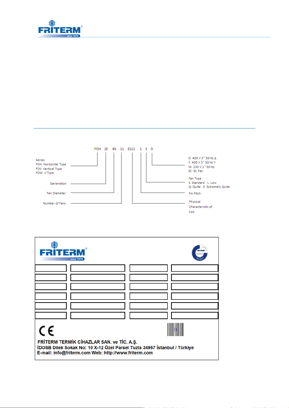
3.1 Product code
3.2 Type plate
Type FDH 2E 8012 E121 3 SD- 6p Fan speed ( Δ/ Y) 890/ 690 rpm
Serial Nr. Total Power
TS min/ max. - 40/ +110 °C Power Supply 400 V AC 3 Ph 50 Hz
Dry Weight
Internal Vol.
Medium Water- Glycol/ Fluid G2 Prod. Year
409 kg
41.4 L.
Max. Opr. Pr. 16 Bar
Test Pr. / Medium 20 Bar/ Dry Air
( Δ/ Y) 3.6/ 2.3 kW
Rev. Tarihi:25.05.2016 Rev.No:9 Dok. No: KLV.004.ENG
Page 15
12
3.3 Friterm Logo
4. TECHNICAL DATA
4.1 Standards
• 97/23/EC PED (Pressure Equipment Directive)
• EN 378 “Refrigeration systems and heat pumps, technical safety and environmental
requirements”
• Capacity standard for dry coolers is defined according to the EN 1048 standard with
the ratio of % 34 ethylene glycol. (
Test methods for establishing the performance)
• The system installer is responsible for that the inherent installation and security
information are harmonized with the valid standards and guidelines (DIN EN 292 /
294).
4.2 Product
The basic principle is to transfer the return water load in the system to air by the aid of a heat
exchanger including fans. Its working principle is that the air sucked by fans cools the fluid
within the tube while it passing through the fins. Thanks to closed fluid circuit, quantity of
water does not diminish hence it is not needed to add extra water to the system.
The unit is delivered for operation with a specific operating point:
• Air inlet temperature and volumetric flow
• Fluid inlet temperature and volumetric flow
Heat exchangers- Air-cooled liquid coolers dry coolers-
Rev. Tarihi:25.05.2016 Rev.No:9 Dok. No: KLV.004.ENG
Page 16

13
4.3 Fans
• Highly efficient axial Ziehl Abegg, EBM or equivalent fans are used.
• Fans diameters: Ø800/ Ø910 mm
• 400V 3~50Hz,
• Triphase fans can work at two different speeds. Furthermore, providing speed control
is optional for EC fans.
• Variable fan speed regulation can be achieved using triphase fans with frequency
inverter and sine filter.
• Variable voltage speed control system could be used as an alternative fan speed
control system.
• All motors are suitable for speed control applications up to 100 %.
• All motors have feature internal thermal protection.
• Standard wiring of all motors are for one speed.
• Working temperature for exterior mounting is between -40 ºC and +50 ºC - +70 ºC.
• Fans are designed with assuming fans working Fans run in a housing designed to
maximize air flow.
• Recommended starting for motors is 6 starts per hour, maximum starting for motors is
10 starts per hour.
• In case of prolonged stoppage of system, run the fan motors at least 4 hours per week.
• Motor protection IP54; insulation class F.
• Friterm reserves the right to use fans of different manufacturers. Depending on the
type, the fan data may slightly vary.
Rev. Tarihi:25.05.2016 Rev.No:9 Dok. No: KLV.004.ENG
Page 17
14
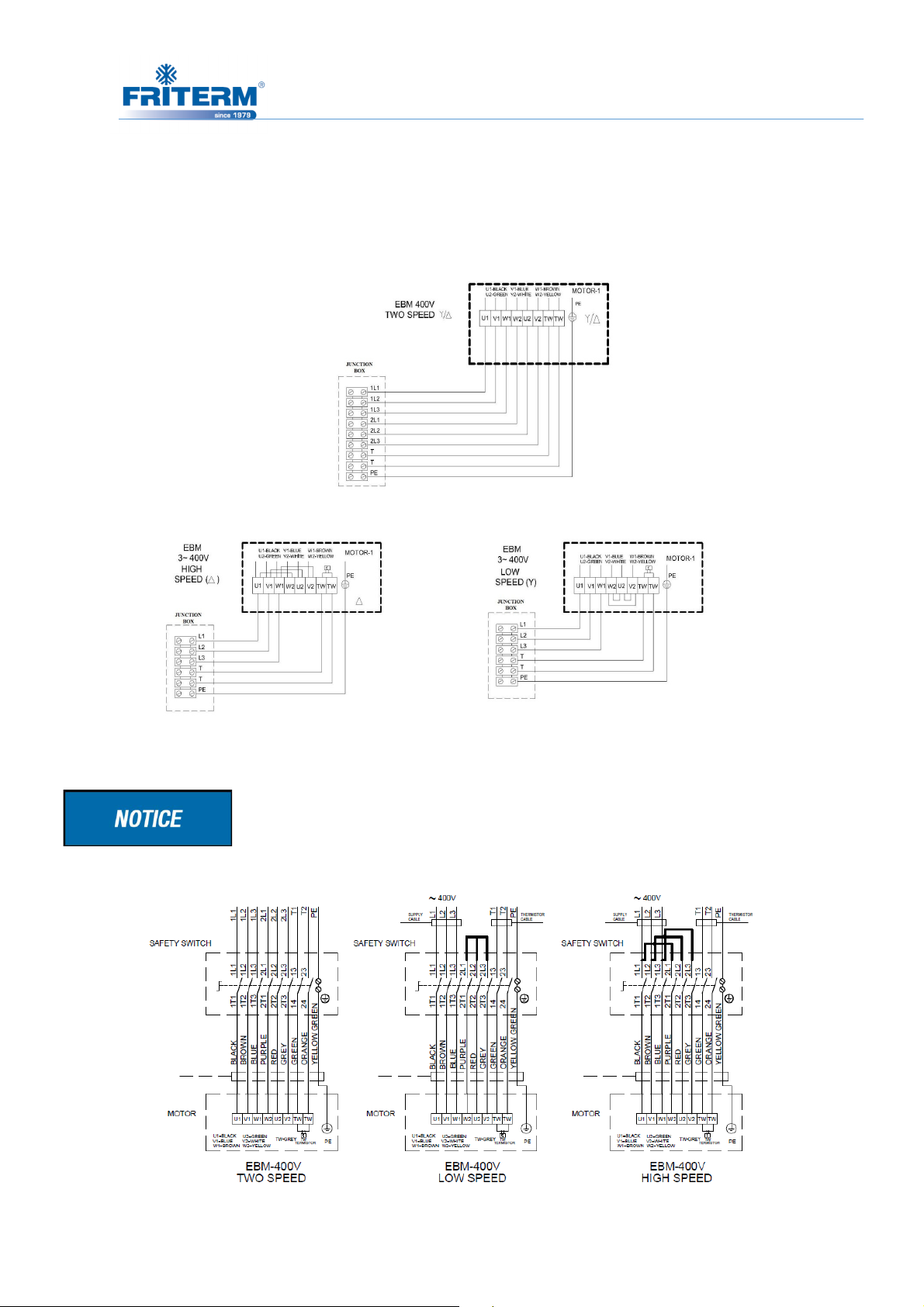
4.3.1 Fan connection diagrams
EBM 400V Fan Connection Diagram
Only specified section in bold lines are scope of supply.
Wiring of Safety Switch and Motor
Rev. Tarihi:25.05.2016 Rev.No:9 Dok. No: KLV.004.ENG
Page 18
15
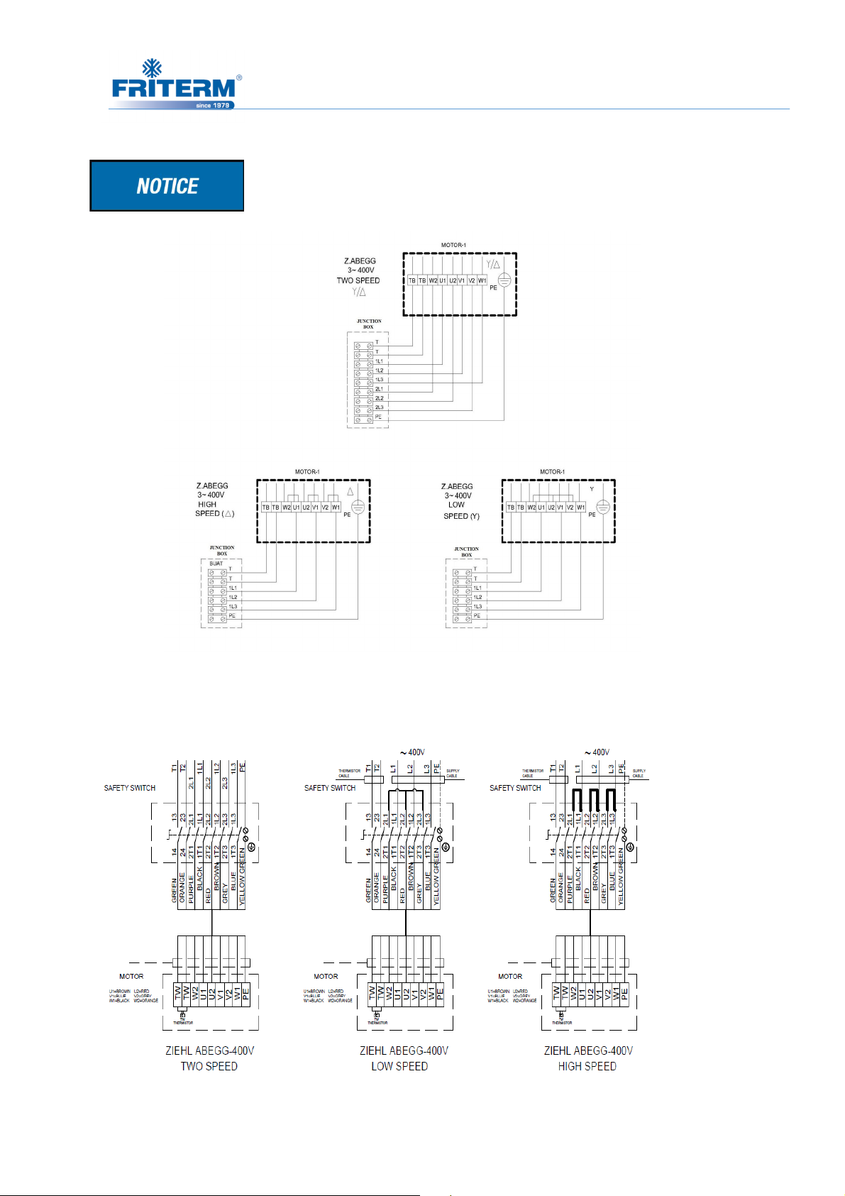
Z.ABEGG 400V Fan Connection Diagrams
Only specified section in bold lines are scope of supply.
Wiring of Safety Switch and Motor
Rev. Tarihi:25.05.2016 Rev.No:9 Dok. No: KLV.004.ENG
Page 19
16
4.4 Control Systems
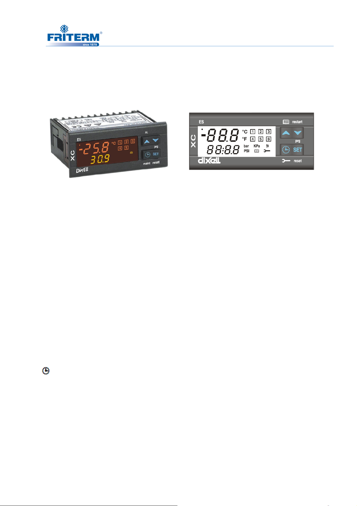
4.4.1 Thermostat (Dixell XC650C) Keyboard
Dixell XC650C thermostat
SET: To see or modify the set point. In programming mode it selects a parameter or confirms
an operation.
Alarm Menu: By holding it pressed for 3 s, the current alarm is erased.
▲ (UP) TO enter the Alarm menu:
In programming mode: it browses the parameter codes or increases the displayed value.
With Hot key inserted: it starts the Hot key programming procedure.
▼ (UP) TO enter the Alarm menu: it browses the parameter codes or decreases the
displayed value.
Manual restart of loads: By holding it pressed for 3s, it switches on again loads previous
locked by a safety digital input alarm.
CLOCK: To display the loads running hours.
By holding it pressed for 3s the Maintaining menu is entered.
KEY COMBINATIONS
▲+ ▼ To lock and unlock the keyboard.
SET + ▼ To enter the programming mode.
SET + ▲ To exit the programming mode.
Rev. Tarihi:25.05.2016 Rev.No:9 Dok. No: KLV.004.ENG
Page 20
bar
PSI
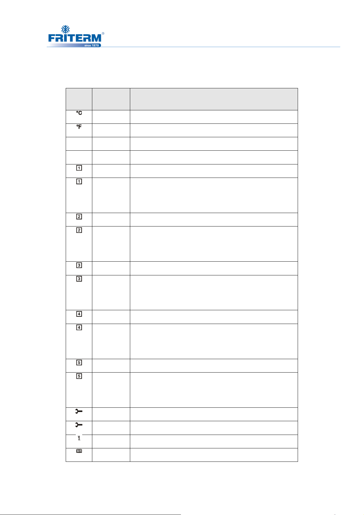
4.4.2 Icons
LED FUNCTIO
17
MEANING
N
ON Celsius degrees
ON Fahrenheit degrees
ON Bar displaying
ON PSI displaying
ON Load 1 on
Flashing Load 1 is waiting to start (1HZ). Or digital input alarm for
Load 1 (2Hz).
o Load 1 in maintenance status (2Hz).
ON Load 2 on
Flashing Load 2 is waiting to start (1HZ). Or digital input alarm for
Load 2 (2Hz).
o Load 2 in maintenance status (2Hz).
ON Load 3 on
Flashing Load 3 is waiting to start (1HZ). Or digital input alarm for
Load 3 (2Hz).
o Load 3 in maintenance status (2Hz).
ON Load 4 on
Flashing Load 4 is waiting to start (1HZ). Or digital input alarm for
Load 4 (2Hz).
o Load 4 in maintenance status (2Hz).
ON Load 5 on
Flashing Load 5 is waiting to start (1HZ). Or digital input alarm for
Load 5 (2Hz).
o Load 5 in maintenance status (2Hz).
ON The Maintenance menu has been entered
Flashing One or more loads have been placed in maintenance status
ON Alarm is happening.
ON All the stored alarms have been seen.
Rev. Tarihi:25.05.2016 Rev.No:9 Dok. No: KLV.004.ENG
Page 21
18
SEtc
SEtF
oA1*
oA2*
oA3*
oA4*
oA5*
ctYP
StP
Pc1
Pc2
Pc3
Pc4
Pc5
FtYP
rtY
CH
StY
rot*
Pbc*
PA04
PA20
P2P*
Flashing A new alarm has happened.
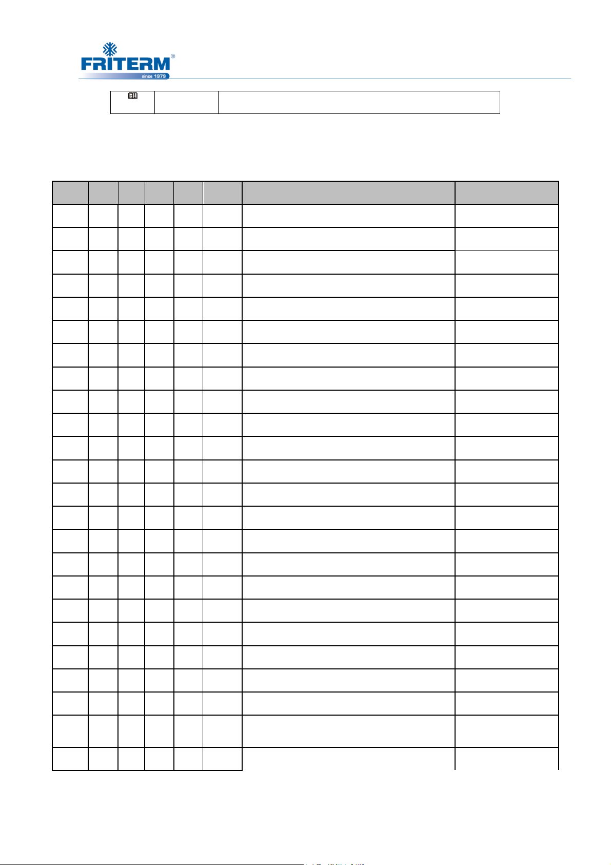
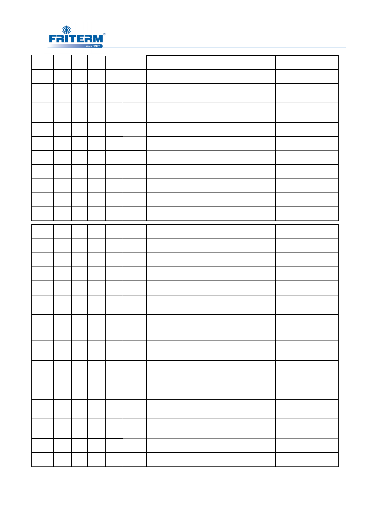
4.4.3 Parameters
Name °C °F Bar PSI Level Description Range
-18
35
CPr CPr CPr CPr Pr2 Outputs 1 configuration FAN
CPr CPr CPr CPr Pr2 Outputs 2 configuration FAN
CPr CPr CPr CPr Pr2 Outputs 3 configuration FAN
FAN FAN FAN FAN Pr2 Outputs 4 configuration FAN
FAN FAN FAN FAN Pr2 Outputs 5 configuration FAN OR NU
SPo SPo SPo SPo Pr2 Compressor type Spo/dPo/Scr
CL CL CL CL Pr2 Valve outputs polarity oP/cL
20 20 20 20 Pr2 Power of compressor 1 0÷255
20 20 20 20 Pr2 Power of compressor 2 0÷255
20 20 20 20 Pr2 Power of compressor 3 0÷255
20 20 20 20 Pr2 Power of compressor 4 0÷255
2,3 33 -- Set point of compressors LSE÷HSE
0
15,1 220 -- Set point for fans LSF÷HSF
95
cAL
20 20 20 20 Pr2 Power of compressor 5 0÷255
404 404 404 404 Pr2 Freon Type r22/404/507/134/717
db db db db Pr2 Type of regulation db/Pb
cL cL cL cL Pr2 Type of action cL/Ht
yES yES yES yES Pr2 Compressor rotation no/YES
yES yES yES yES Pr2 Fans rotation NO
Cur Cur Cur Cur Pr2 Probe 1 setting NTC
0,5 7 0,5 7 Pr2 Adjustment of read out for the Probe at 4mA 0.0 bar o 0 PSI÷PA20
12 174 12 174 Pr2 Adjustment of read out for the Probe at 20mA PA04÷51.0bar o 750 PSI
0 0 0 0 Pr2 Probe 1 calibration
yES yES yES yES Pr2 Second probe presence YES
-12÷12.0°C o bar / -20
÷20°F o PSI
Rev. Tarihi:25.05.2016 Rev.No:9 Dok. No: KLV.004.ENG
Page 22
19
Pbc2
*
FA04
SEP
HPP
i1c
i1F
did
AliP
ALMr
Cur Cur Cur Cur Pr2 Probe 2 setting NTC
1 14 1 14 Pr2 Adjustment of read out for the Probe at 4mA 0.0 bar o 0 PSI ÷ FA20
FA20
FcAL
dEu
rES
dSP2
31 450 31 450 Pr2 Adjustment of read out for the Probe at 20mA
0 0 0 0 Pr2 Probe 2 calibration
CL CL CL CL Pr2 Low pressure switch input polarity oP/cL
CL CL CL CL Pr2 High pressure switch input polarity oP/cL
cL cL cL cL Pr2 Configurable digital input polarity oP/cL
ES ES ES ES Pr2 Configurable digital input polarity functions ES / oFF / LL
0 0 0 0 Pr2 Configurable digital input delay 0 ÷ 255 min.
CL CL CL CL Pr2 Alarm input for compressors and fans polarity oP/cL
no no no no Pr2 Manual reset of alarms for compressors and fans no/YES
°C
dE
P1 P1 P1 P1 Pr2 Default visualization of lower display nu-P1-P2-SEt1-SEt2
bar PSI Pr2 Default measurement unit for displaying bar/°C/PSI/°F
°F
dE in Pr2 Resolution for °C and bar in/dE
in
FA04 ÷ 51.0 bar o750
PSI
-12÷12.0°C o bar / -20
÷20°F o PSI
dEU2
rELP
Pbd
Esc
onon
oFon
don
doF
donF
Maon
PrS PrS PrS PrS Pr2 Lower display probe format PrS ÷ tPr
rEL rEL rEL rEL Pr2 Pressure displaying rEL/AbS
4 8 0.5 7 Pr2 Proportional band or neutral zone width
0 0 0 0 Pr2 Energy saving value for compressors
5 5 5 5 Pr2
2 2 2 2 Pr2
0,3 0,3 0,3 0,3 Pr2
0,1 0,1 0,1 0,1 Pr2
0,3 0,3 0,3 0,3 Pr2 Minimum time a stage stays switched ON
0 0 0 0 Pr2 Maximum time for compressor ON 0 ÷ 24 h
Minimum time between2 following switching ON of
the same compressor
Minimum time between the switching off of a
compressor and the following switching on
Time delay between the insertion of two different
compressors
Time delay between switching off of two different
compressors
> +10.0 bar/30.0 °C/80
PSI/50 °F
- + 20.0bar/ - + 50°C/- +
300
PSI/- + 90°F
0 ÷ 255 min.
0 ÷ 255 min.
0 ÷ 99,5 min. ( res. 10
sec.)
0 ÷ 99,5 min. ( res. 10
sec.)
0 ÷ 99,5 min. ( res. 10
sec.)
FdLY
no no no no Pr2 ' don '' delay enabled also for the first call no/YES
Rev. Tarihi:25.05.2016 Rev.No:9 Dok. No: KLV.004.ENG
Page 23
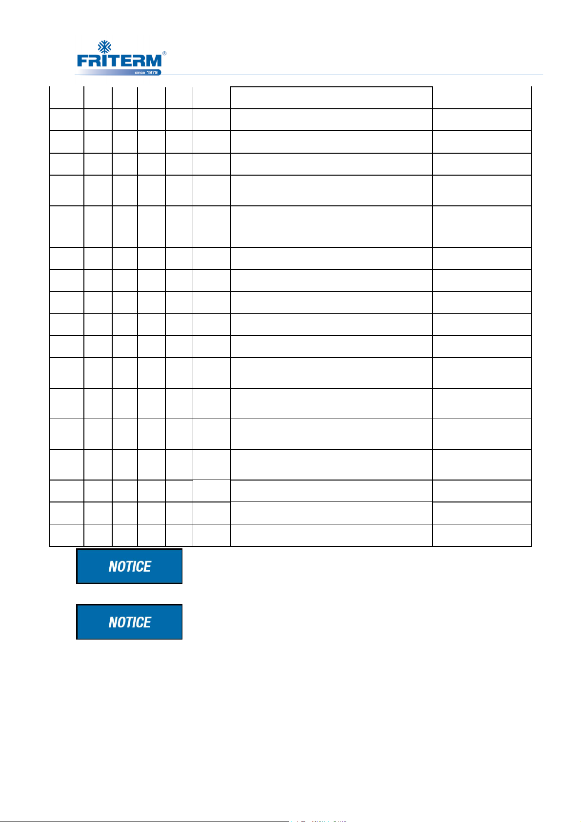
FdLF
20
no no no no Pr2 “doF'' delay enabled also for the first switching off no/YES
odo
LSE
HSE
Pb
ESF
Fon
FoF
LSF
HSF
Pao
LAL
HAL
20 20 20 20 Pr2 Regulation delay on start-up 0 ÷ 255 sec.
-40 -40 0,3 0,3 Pr2 Minimum set point for compressors PA04 ÷ HSE
10 50 7,2 100 Pr2 Maximum set point for compressors LSE ÷ PA20
4 8 2.0 24 Pr2
0 0 0 0 Pr2 Energy saving value for fans
15 15 15 15 Pr2 Time delay between the insertion of two different fans 0 ÷ 255 sec.
5 5 5 5 Pr2 Time delay between switching off of two different fans
10 50 7,2 100 Pr2 Lower set for fans PA04 ÷ HSE
60 140 27,8 404 Pr2 Higher set for fans LSE ÷ PA20
30 30 30 30 Pr2 Alarm probe exclusion at power on 0 ÷ 255 min.
15.0 30 1,5 21 Pr1 Low pressure (temperature) alarm compressor section
20.0 40 2,5 46 Pr1 High pressure (temperature) alarm compressor section
Proportional band or neutral zone
width for fans
0.1÷10.0 bar/30.0°C/80
PSI/50°F
- + 20.0 bar/- + 50.0°C / + 300
PSI/- + 90°F
0 ÷ 255 sec.
> 0÷30.0 bar/100.0
°C/430 PSI/200 °F
> 0÷30.0 bar/100.0
°C/430 PSI/200 °F
tAo
SEr
PEn
PEi
SPr
15 15 15 15 Pr1
999 999 999 999 Pr2 Service request
5 5 5 5 Pr2 Low pressure-switch intervention numbers 0 ÷ 15
15 15 15 15 Pr2 Pressure -switch interventions time 0 ÷ 255 min.
2 2 2 2 Pr2 Number of steps engaged with faulty probe 0 ÷ # compressors
Low and High pressure (temperature) alarms delay-
compressor section
0 ÷ 255 min.
(0 = disable) 1÷ 999; res
10h
The thermostat’s set point is sent programming to 28 ˚C by the
technicians of Friterm A.Ş.
The parameters specified with “ * ” are adjusted according to the
products of Friterm A.Ş.
Rev. Tarihi:25.05.2016 Rev.No:9 Dok. No: KLV.004.ENG
Page 24

21
E0L
Automatically
(DOWN) key for 3s or
E0H
Automatically
(DOWN) key for 3s or
P1*
Automatically
P2*
Automatically
EA1
ALMr
LA
Automatically;
4.4.4 Tables of Alarms
Code Description Cause Action Reset
Low pressure
switch alarm
High pressure
switch alarm
P1 probe
failure alarm
P2 probe
failure alarm
Low
pressure
switch input
enabled
High
pressure
switch input
enabled
Probe failure
or out of
range
Probe failure
or out of
range
All
compressors
are turned off.
Fans
unchanged.
-All
compressors
are turned off.
-All fans are
turned on.
- The
compressors
are activated
according to
the SPr or PoPr
parameters.
- The fans are
activated
according to
the FPr
parameters.
(If the number of activation are
less than PEn in the PEi time) when the input is
disable.
- The compressors restart working according to
the working algorithm.
Manually (If PEn activation happened in the PEi
time) When the input is disable:
a. hold pressed the Restart
b. turn off and on the instrument.
- The compressors restart working according to
(If the number of activation are
less than PEn in the PEi time) when the input is
disable.
- Compressors and fans restart working
according to the working algorithm.
Manually (If PEn activation happened in the PEi
time) When the input is disable:
a. hold pressed the Restart
b. turn off and on the instrument.
Compressors and fans restart working according
to the working algorithm.
as soon as the probe restarts
working.
as soon as the probe restarts
working.
Code Description Cause Action Reset
EA2
EA3
EA4
EA5
Load safeties
alarm
Minimum
pressure
(temperature)
alarm
compressors
Safeties
compressor/f
an input
activation.
NOTE: with
step
compressors
1 input for
each
compressor
has to be
used.
Suction
pressure or
temperature
lower than
SET_C-LAL
- the
corresponding
load is turned
off.(with step
compressors all
relays referred
to the input are
disabled).
- signaling only
Recovery depends on
ALMr = no The instrument restarts the standard
operating mode when the input is disabled.
With ALMr = YES manual recover for the alarms
of compressors and fans. Push the DOWN key for
3s.
as soon as the pressure or
temperature reaches the (Set_C-LAL+
differential) value.
(differential =0.3 bar or 1°C)
parameter: With
Rev. Tarihi:25.05.2016 Rev.No:9 Dok. No: KLV.004.ENG
Page 25
22
LA2
Automatically;
HA
Automatically;
HA2
Automatically;
A5
Automatically;
A14
section
value
Minimum
pressure
(temperature)
alarm fans
section
Maximum
pressure
(temperature)
alarm
compressors
section
Maximum
pressure
(temperature)
alarm fans
section
Liquid level
alarm
Load
maintenance
alarm
Condensing
pressure or
temperature
lower than
SET_F-LAL
value
Suction
pressure or
temperature
higher than
SET_F-HAL
value
Condensing
pressure or
temperature
higher than
SET_F+HAL
Input
enabled
A load has
worked for
the hour set
in the SEr
parameter
- signaling only
- signaling only
- signaling only
- signaling only
- signaling only
as soon as the pressure or
temperature reaches the (Set_F-LAL +
differential) value.
(differential = 0.3 bar or 1 °C)
as soon as the pressure or
temperature reaches the (Set_C+HAL differential) value.
(differential = 0.3 bar or 1 °C)
as soon as the pressure or
temperature reaches the (Set_F+HAL differential) value.
(differential = 0.3 bar or 1 °C)
as soon as the input is disabled
Manually; reset the running hour of the
compressor ( see par.8 Running hours of loads)
Only two alarms specified with “ * ” is activated by Friterm A.Ş
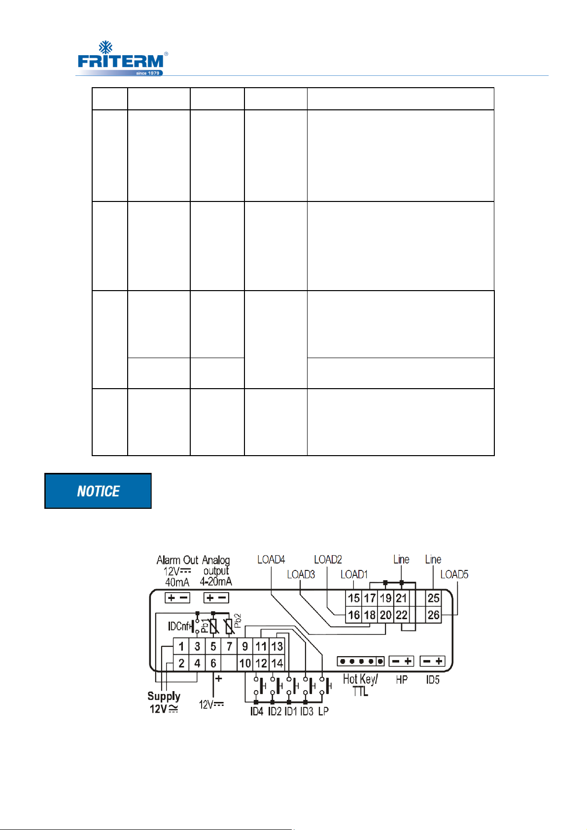
4.4.5 Wiring Connection:
.
Rev. Tarihi:25.05.2016 Rev.No:9 Dok. No: KLV.004.ENG
Page 26

23
Fan Number
LOAD1
LOAD2
LOAD3
LOAD4
LOAD5
1 FAN
1 FAN
-Y
1 FAN
-∆
ECOMESH OR
2 FAN
1 FAN
-Y
2 FAN
-Y
2 FAN
-∆
ECOMESH OR
3 FAN
1 FAN
-Y
2 FAN
-Y
3 FAN
-Y
3 FAN
-∆
ECOMESH OR
4 FAN
2 FAN
-Y
1 FAN
-Y
1 FAN
-Y
4 FAN
-∆
ECOMESH
OR
5 FAN
2 FAN
-Y
2 FAN
-Y
1FAN
-Y
5 FAN
-∆
ECOMESH OR
6 FAN
2 FAN
-Y
2 FAN
-Y
2 FAN
-Y
6 FAN
-∆
ECOMESH OR
7 FAN
3 FAN
-Y
2 FAN
-Y
2 FAN
-Y
7 FAN
-∆
ECOMESH OR
8 FAN
4 FAN
-Y
2 FAN
-Y
2 FAN
-Y
8 FAN
-∆
ECOMESH OR
10 FAN
4 FAN
-Y
2 FAN
-Y
4 FAN
-Y
10 FAN
-∆
ECOMESH OR
12 FAN
4 FAN
-Y
4 FAN
-Y
4 FAN
-Y
12 FAN
-∆
ECOMESH OR
14 FAN
4 FAN
-Y
4 FAN
-Y
6 FAN
-Y
14 FAN
-∆
ECOMESH OR
16 FAN
6 FAN
-Y
6 FAN
-Y
4 FAN
-Y
16 FAN
-∆
ECOMESH
OR
18 FAN
6 FAN
-Y
6 FAN
-Y
6 FAN
-Y
18 FAN
-∆
ECOMESH OR
20 FAN
6 FAN
-Y
6 FAN
-Y
8 FAN
-Y
20 FAN
-∆
ECOMESH OR
4.4.6 The Adjustment of Thermostat Control Part According to the Application of
Different Fan Number
LIQUID SPREY
LIQUID SPREY
LIQUID SPREY
LIQUID SPREY
LIQUID SPREY
LIQUID SPREY
LIQUID SPREY
LIQUID SPREY
LIQUID SPREY
LIQUID SPREY
LIQUID SPREY
LIQUID SPREY
LIQUID SPREY
LIQUID SPREY
Rev. Tarihi:25.05.2016 Rev.No:9 Dok. No: KLV.004.ENG
Page 27
24
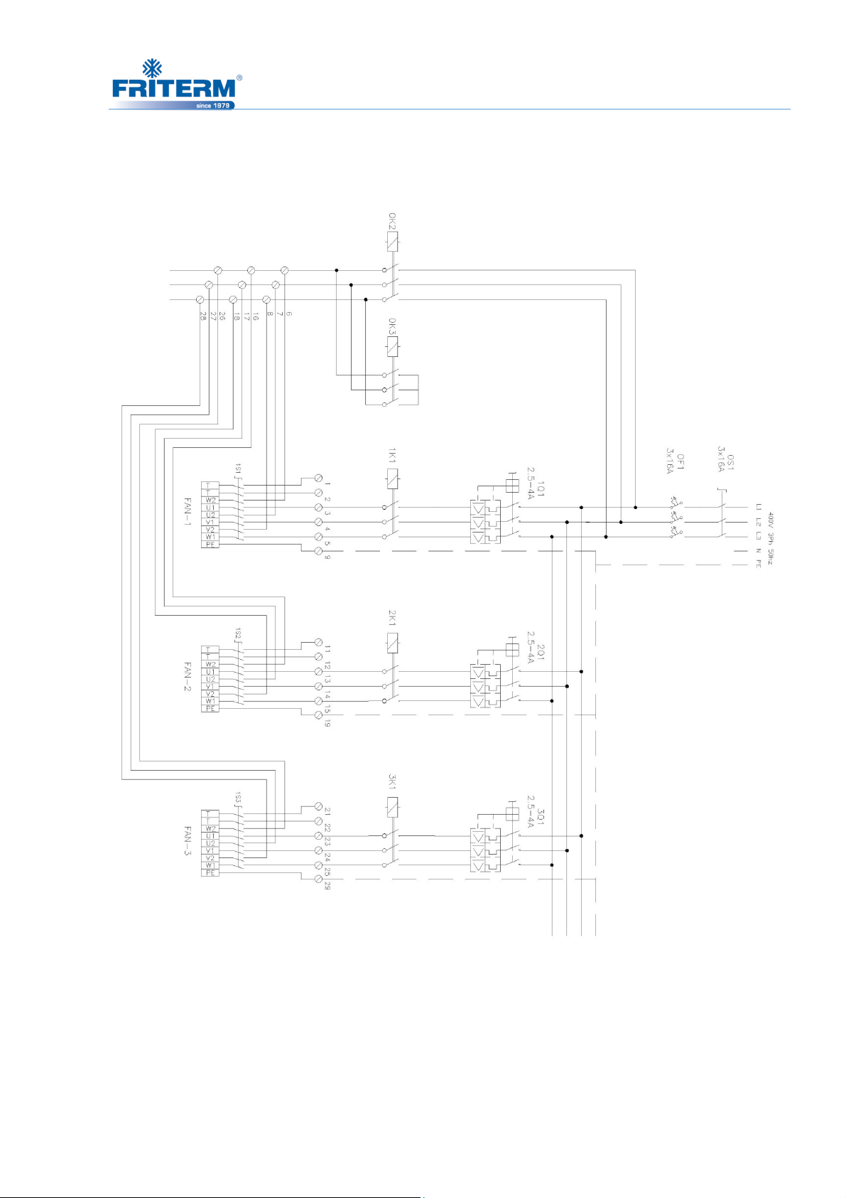
4.4.7 Power Circuit Wiring
Rev. Tarihi:25.05.2016 Rev.No:9 Dok. No: KLV.004.ENG
Page 28
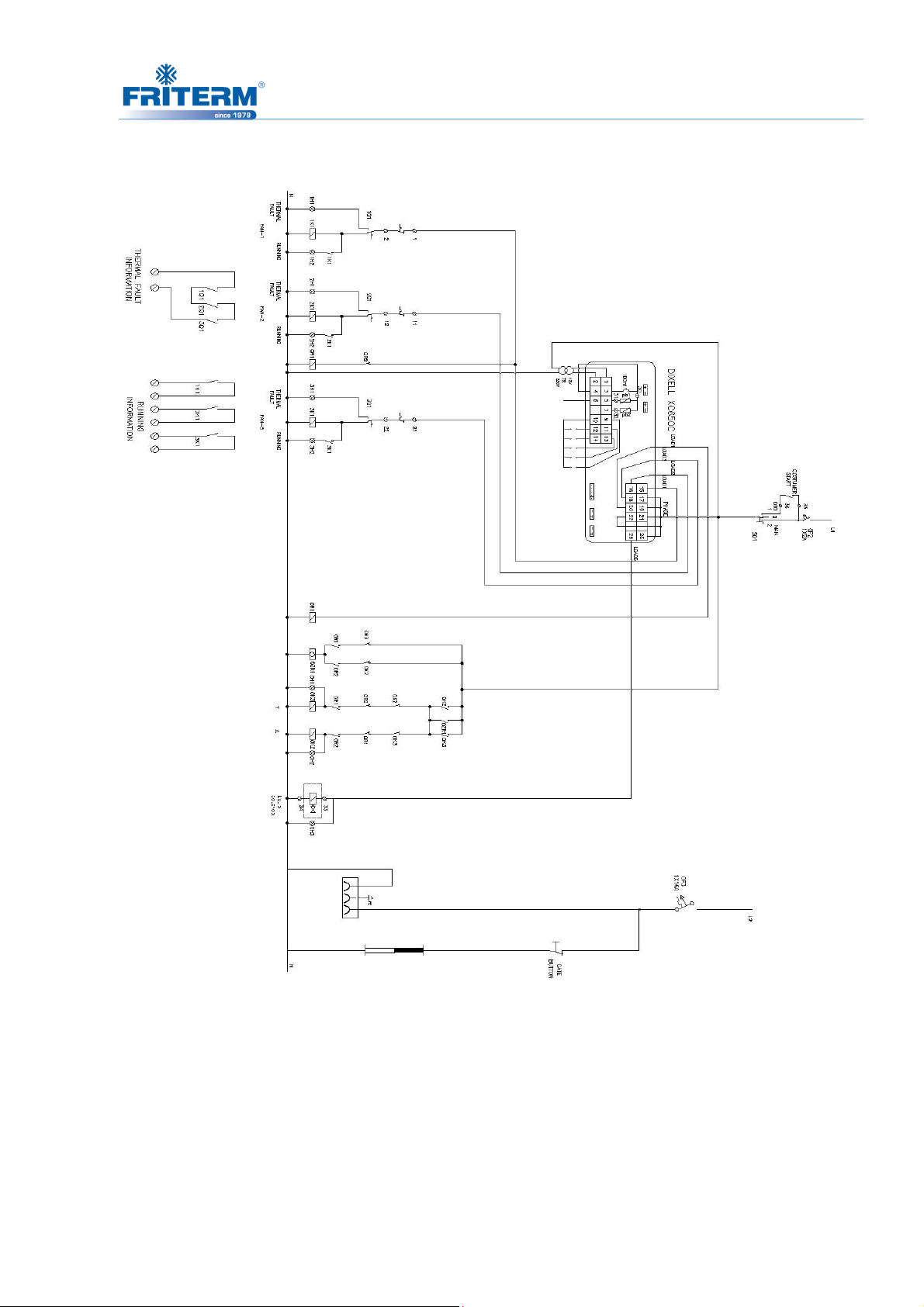
4.4.8 Control Wiring
25
Rev. Tarihi:25.05.2016 Rev.No:9 Dok. No: KLV.004.ENG
Page 29
26
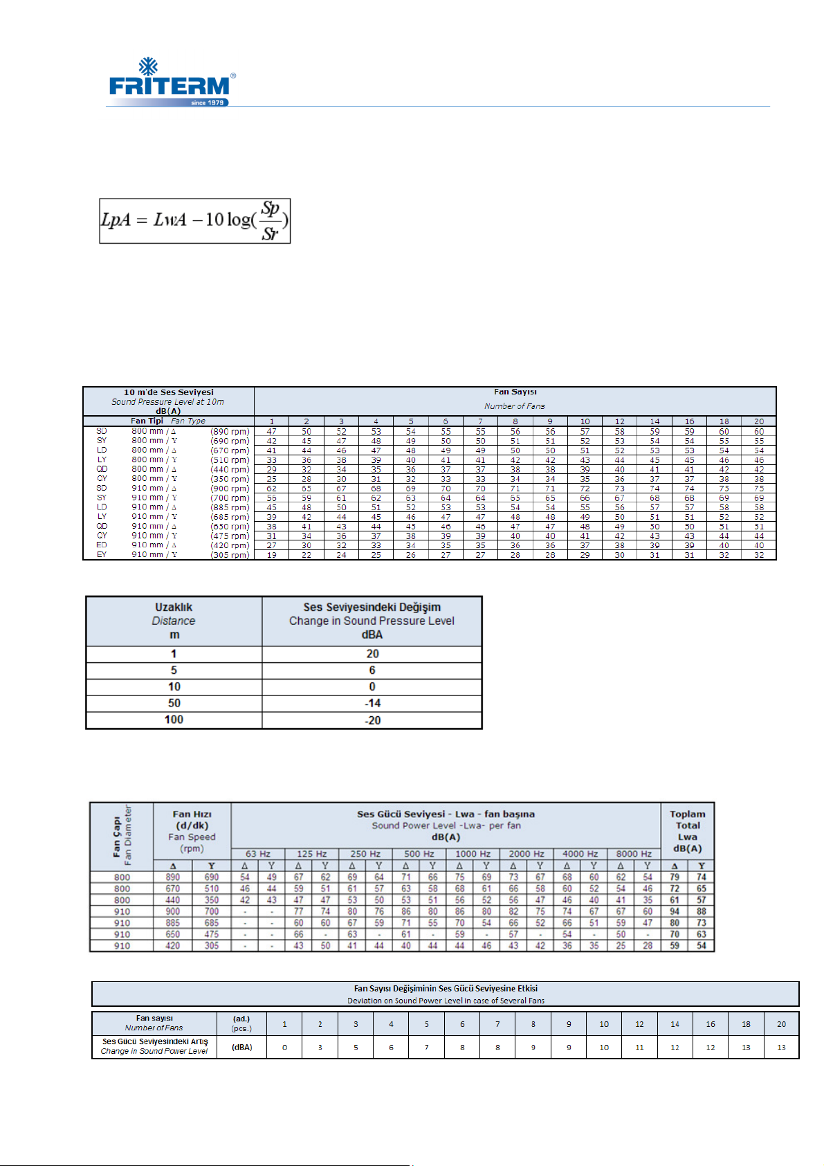
4.5 Sound pressure level
Noise pressure levels (LpA) are determined from the sound power levels (LwA) by using
following formula according to EN 13487 Surrounding Surface Method.
Sp = parallel piped surface at 10 m
Sr = surface reference(1m2)
Sound pressure levels given show the average values on a parallelpiped surface at 10 m
distance from the unit in open air over a reflecting plain.
4.6 Sound power level
Rev. Tarihi:25.05.2016 Rev.No:9 Dok. No: KLV.004.ENG
Page 30
27
5. TRANSPORT AND STORAGE
5.1 Check for completeness and transport damage
• Attention! May cause severe injuries or unrecoverable damages in case of
uncontrolled fall down.
• Instructions on lift and transportation should be strictly followed.
• Check if there is any damage on product or package. Immediately after receipt, the
delivery must be inspected for possible transport damage. Any damage must be
reported immediately to the shipping company. If it is to be expected that the transport
damage may affect proper operation, then the product must not be commissioned.
• Upon receipt, the product should be visually inspected, and in case of any damage or
shortage, the supplier should be notified within 7 days.
5.2 Transport
The product may only be lifted and moved by persons who:
1. Are authorised to operate crane systems,
2. Are authorised to drive motorised handling product
3. Also know the transport and lifting instructions according to the operating manual and
the assembly drawing.
Suitable transport equipment must be used.
Rev. Tarihi:25.05.2016 Rev.No:9 Dok. No: KLV.004.ENG
Page 31
28
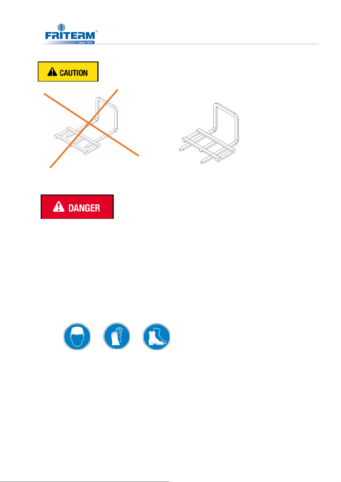
Only lift the packed unit with a forklift with full work length.
FALSE TRUE
Risk of accident due to falling load
The size and weight of the product may cause accidents while transporting.
• Be extremely careful during transport to avoid damage or deformation on the product.
• Only use suitable transport equipment and lifting gear with sufficient load-bearing
capacity.
• All precautions should be taken against any possible mechanical risk.
• Never stand or work under suspended loads.
• Wear appropriate protective clothing (helmet, safety gloves, safety shoes).
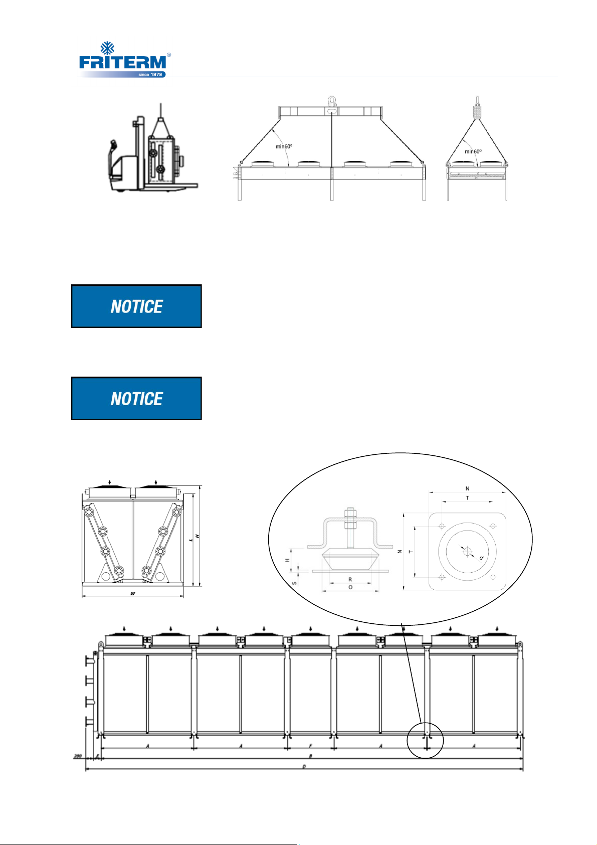
• During lifting, a suitable lifting tool like a forklift or a crane is to be operated as in the
drawings below. When lifting the product with hauling hooks, it is necessary to use a
lifting beam connected to the hooks.
• Product is mounted with wooden beams at the bottom. It can be placed on the ground
on these wooden beams. These wooden beams provide enough height for forklifts.
During landing the product onto the ground, be careful for the notches on the ground
and prevent defects of the aluminium fins below the product.
Rev. Tarihi:25.05.2016 Rev.No:9 Dok. No: KLV.004.ENG
Page 32
29
Handling scheme during carriage
If lightweight product is to be handled without a lifting vehicle, excessive care should be
taken and suitable gloves should be used.
Be careful not to damage the product by the forks of the forklift. In order not to scratch
the product, place a separator material. (cardboard, plywood, isolation material etc.)
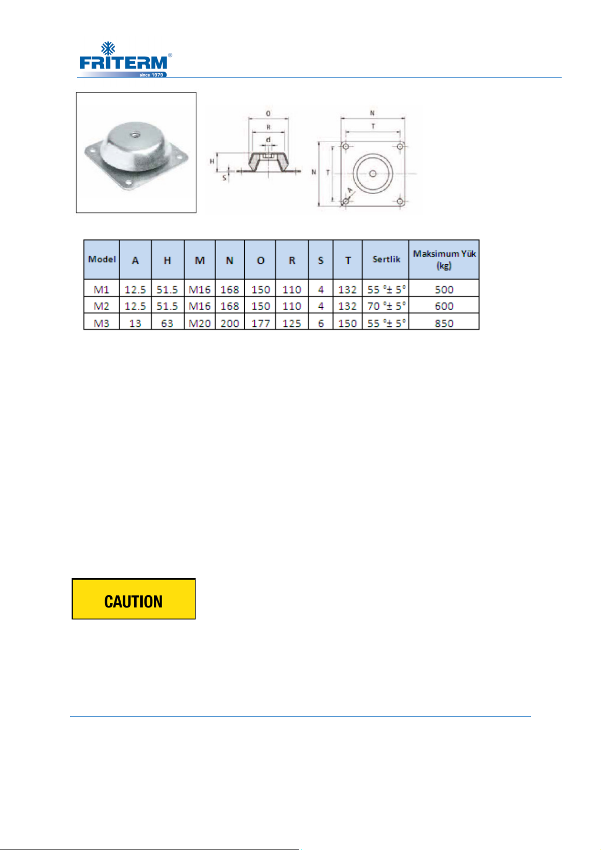
Vibration absorber stand mounting detail is given as follows. The absorber should be
fixed to the floor with suitable size bolts.
Rev. Tarihi:25.05.2016 Rev.No:9 Dok. No: KLV.004.ENG
Page 33
30
5.3 Storage
• Store the product in the original packaging in order to protect from improper weather
conditions, dirt, moisture and environmental effects and the equipment.
• Avoid excessive storage periods (one year of storage at maximum is recommended).
• If the product is stationary for long periods in a humid atmosphere, the fans should be
switched ON for minimum four hours per a month to remove moisture that may have
condensed within the motors
• Pay attention to the instructions on visual signs and labels for safety transport and
handling of packaged product.
• Avoid exposure to extreme heat and cold.
Damage caused by improper storage
Incorrect or improper storage may cause damage to the radiator or radiator components.
6. INSTALLATION
The system installer is responsible for the proper installation according to standards and
guidelines (DIN EN 292 / 294) which contains installation and security guidelines.
Rev. Tarihi:25.05.2016 Rev.No:9 Dok. No: KLV.004.ENG
Page 34
Before installing, it must be ensured that the technical specifications of the
accordance with the desired working conditions.
6.1 Location
is designed only for permanent installation. It should be fixed to a stable base.
The working fluid, the maximum working pressure and the voltage declared by the producer
should be proper for the working environment.
area should be well ventilated and should not be contained any hazardous
Air motion should not be adversely affected by obstructions and inlet air should not be
undesirably heated or cooled by some other
bolts and/or flanges should be removed right before the installation.
The site where the installation process is being carried out should be provided as clean
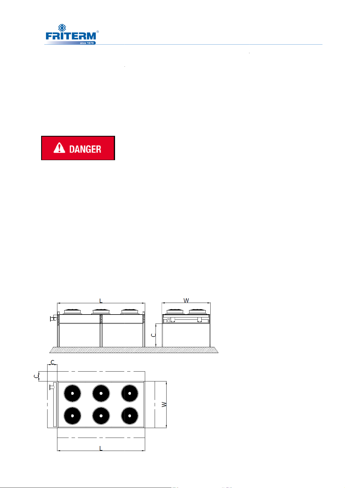
6.2 Requirements at the set up point
H
Rev.No:9 Dok. No: KLV.004.ENG
∗
∗
Condition:
6.2.2 Set up next to wall
The product
The working
substances or explosives.
•
31
product are in
product.
• All the blind
•
as possible.
6.2.1 Outdoor set up of FC
unit
2
(m2)
∗
∗ 0,65
Rev. Tarihi:25.05.2016
Page 35
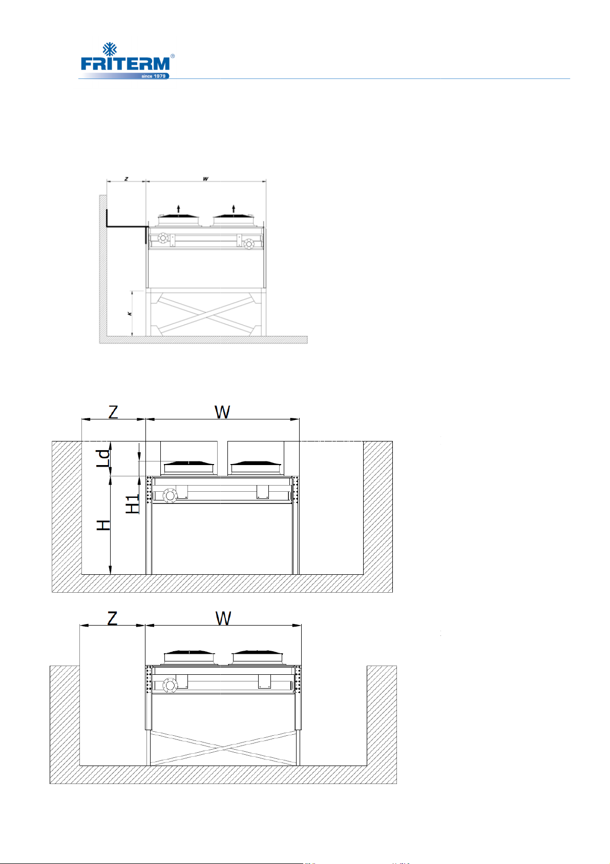
blowing air because of the side wall,
to facilitate suction from
the dry cooler) or higher extended legs must be used
Rev.No:9 Dok. No: KLV.004.ENG
prevention accessori
the bottom, raising chassis (with a high of half
Condition;
Fans with ventilation
channel:
450
Condition;
Fans with Friterm
Streamer:
Fans without Friterm
Streamer:
To avoid the by- pass of the
be used and
32
es must
-width of
(700-1200 mm).
K ≥ W/2
6.2.3 Set up in pit-hallow
0,5 ∗
600 mm
Rev. Tarihi:25.05.2016
0,5 ∗
0,65 ∗
Page 36
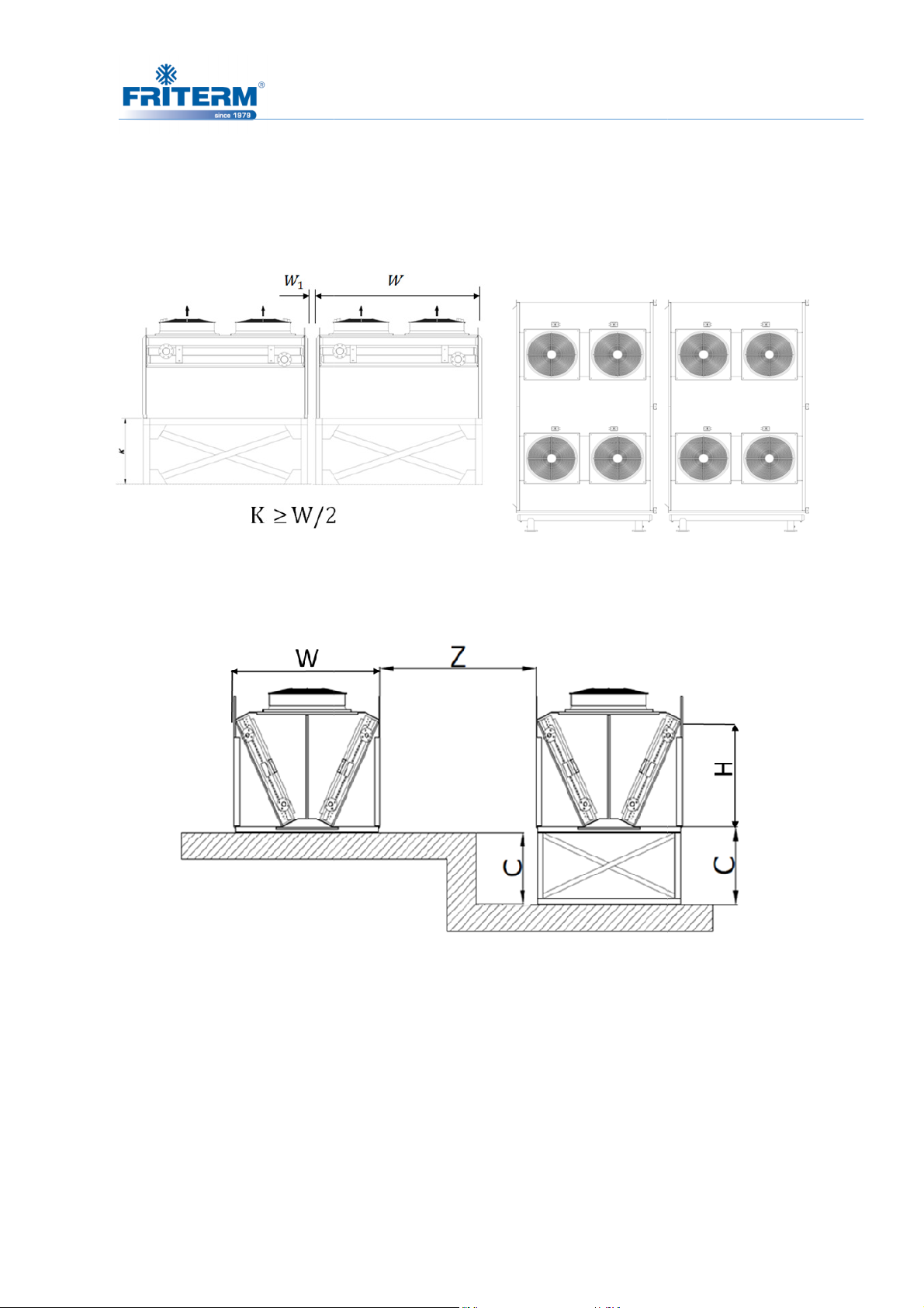
6.2.5 Requirements at the set up po
value must be set by taking into account the top level of units.
double of width of the product
Rev.No:9 Dok. No: KLV.004.ENG
Z must be equal to the
6.2.4 Several FDH units
Condition: ≅ 100 mm
33
int (FDW units)
Z =2 x W
C
.
Rev. Tarihi:25.05.2016
Page 37
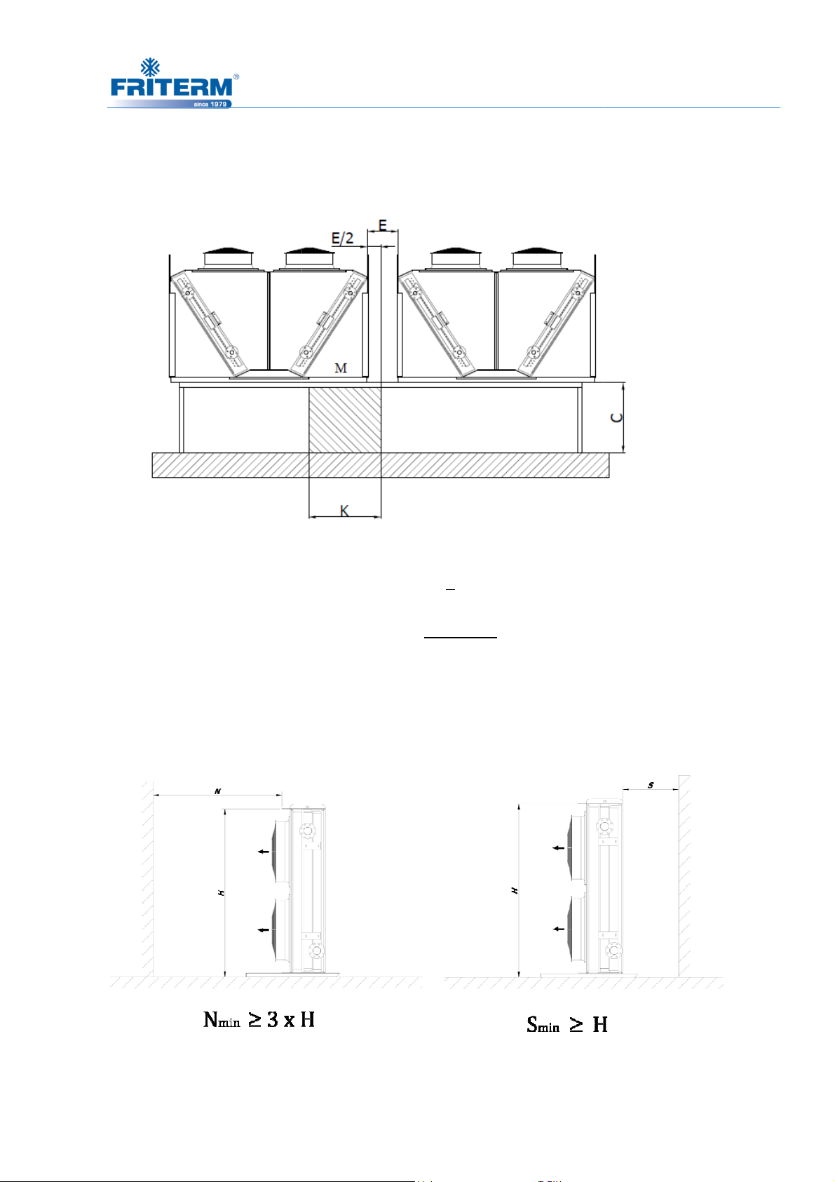
6.2.6 Several FDW units
irements at the set up point (F
Rev.No:9 Dok. No: KLV.004.ENG
34
6.2.7 Requ
!""#"$%&'!""#(!$&%
K M
E
2
FlowArea
C n 1
E =100 mm
n= Number of
dry cooler
Kx2
DV units)
Rev. Tarihi:25.05.2016
Page 38
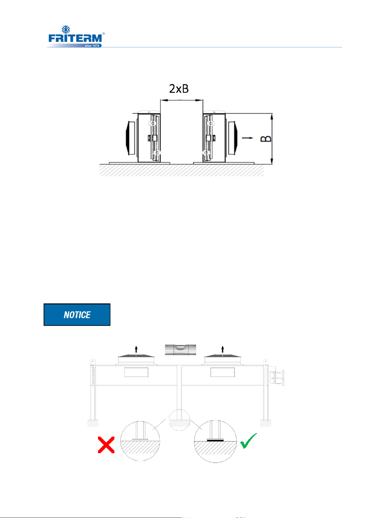
6.2.8 Side-by-side setup (FD
V
must be provided by users in their plants during mounting against to any
should not be faced with any obstacle because of any restriction.
Additional pressure should not be created by fans or motors which are located next to the
Installation and electrical connection must be performed by
while unpacking and installing products in order not to cause any damage to the
All the legs of the dry cooler must st
Rev.No:9 Dok. No: KLV.004.ENG
qualified personnel.
and on floor and the unit should be levelled.
6.3 Mounting
Stability of units
vibration.
35
units)
Air flow
product.
Be careful
tubes and piping connections.
only
Rev. Tarihi:25.05.2016
Page 39
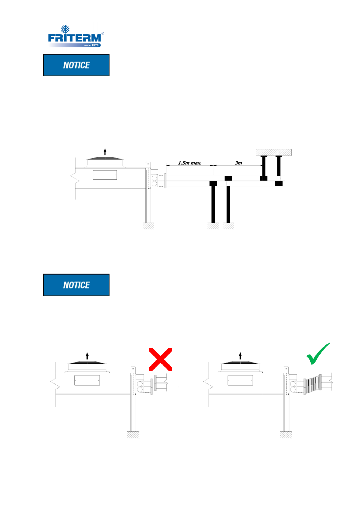
Piping should be fixed and supported at a distance of 1.5 m from the unit connection. After
the first supporting point the entire piping should be fixed at each 3 m.
The flanged connection to the dry
flexible vibration absorber intermediate connector should be used.
Rev.No:9 Dok. No: KLV.004.ENG
cooler should be made at perfect facing position. Unless, a
36
Rev. Tarihi:25.05.2016
Page 40
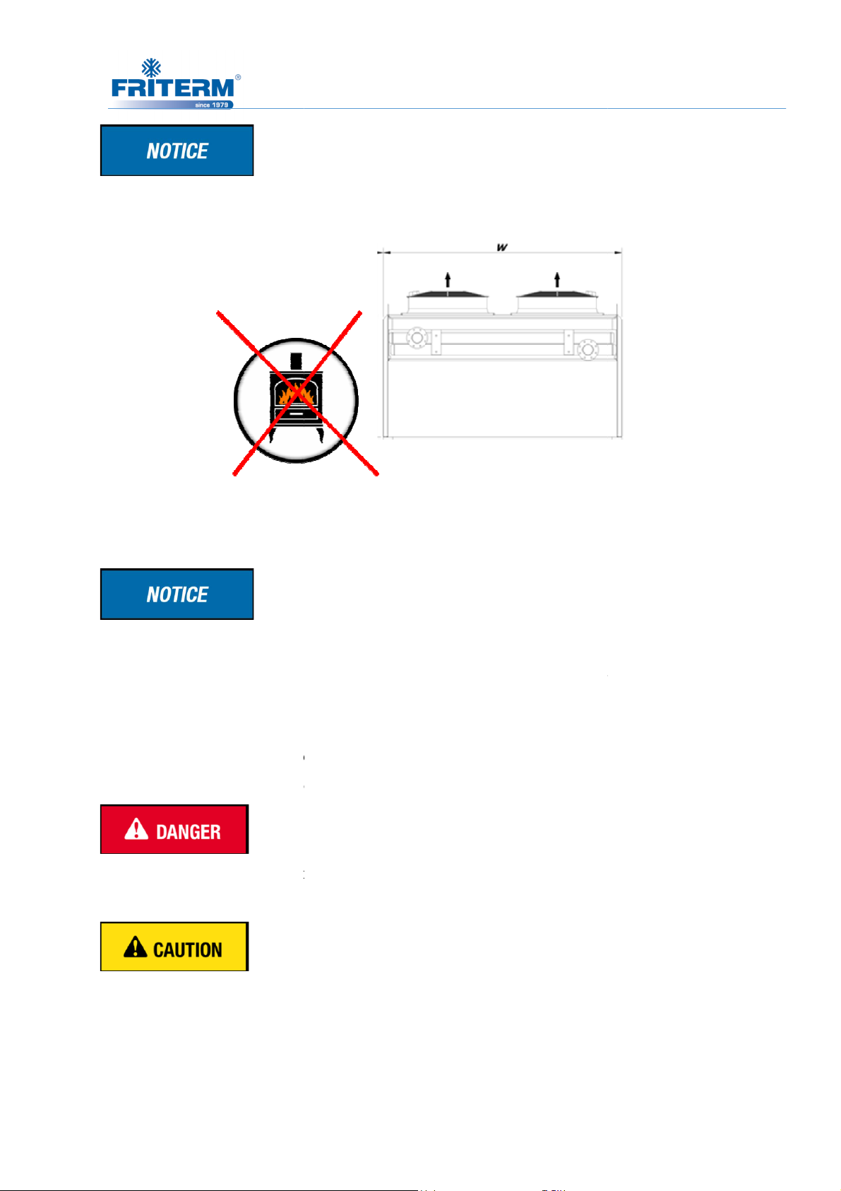
There should be NO Heat Source close to the dry cooler, especially hot air outlet ducts.
electrical supply connection exists during installation.
product
The connections used for mounting should be adequate to support the total operational forces.
mounted in such a way that no vibration would be carried to the product
(vibration dampers can be used if required).
Carrier legs and lifting lugs are delivered as mounted on
must not be done before mounting the
must not be operated and electrically connected before the mounting legs fixed.
Rev.No:9 Dok. No: KLV.004.ENG
should be in accordance with its design.
to the ground with
37
It must be ensured that no
The mounting position of the
The product must be
Electrical connections
the legs.
product
product
Product
Rev. Tarihi:25.05.2016
Page 41
38
6.3.1 Ideal mounting scheme
6.3.2 Leg mounting
Legs have been delivered demounted with the product.
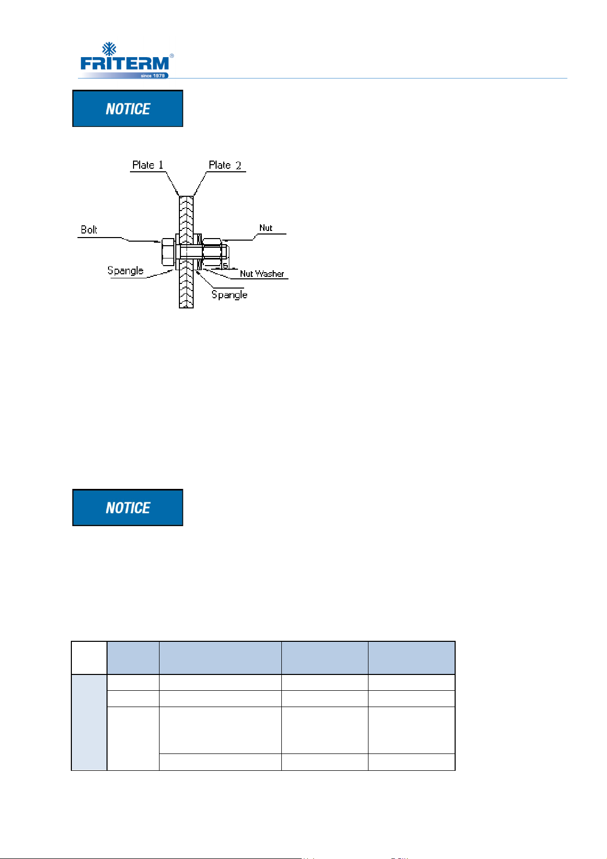
For every leg; 6 piece M10x25 nut, M10 bolt and 12 piece spangles are given. The product is
delivered with lifting eyes. The product is delivered with lifting eyes mounted on it.
While mounting the product, number of legs that must be used depending on current fan
counts is specified in the table given below.
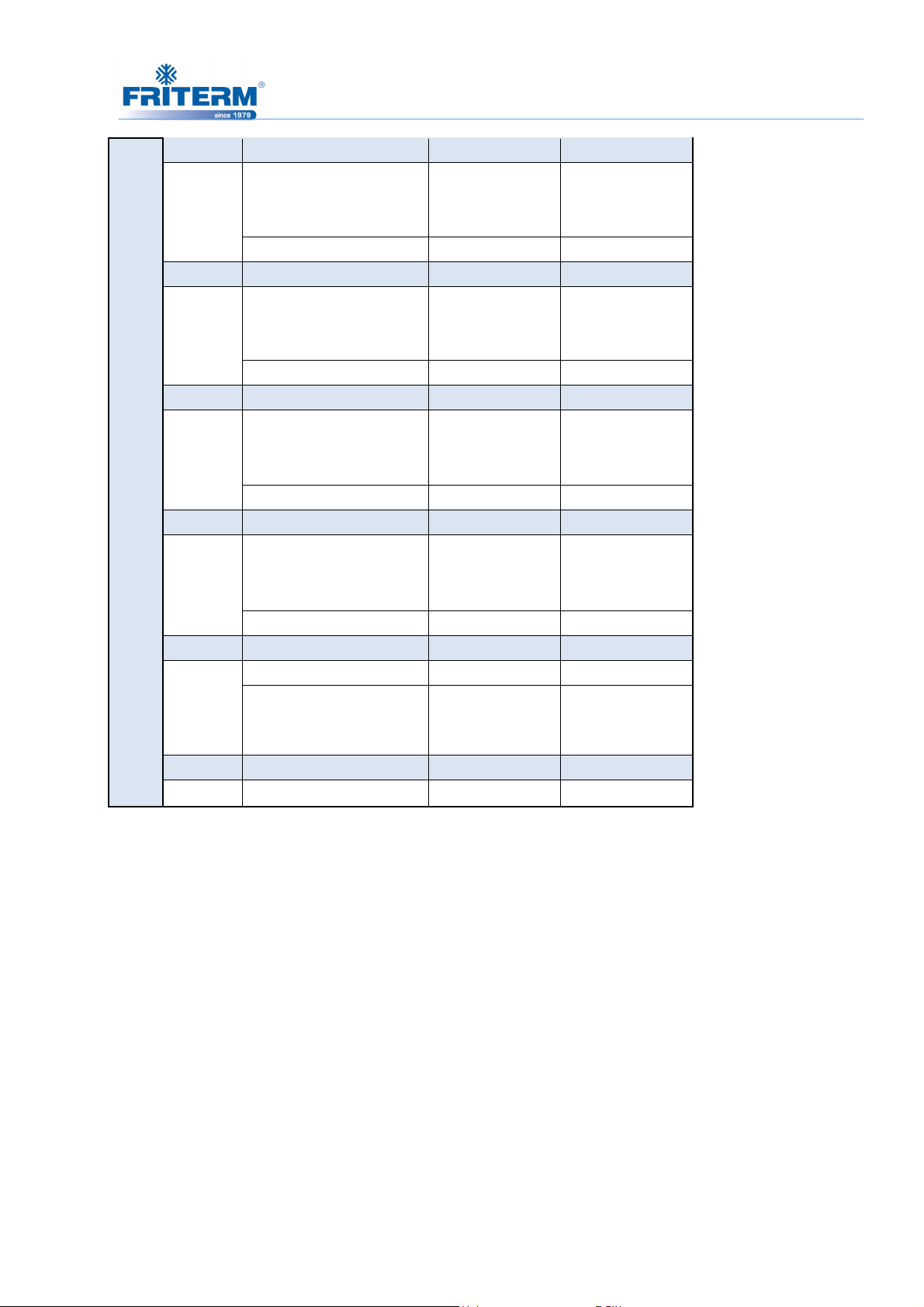
Same leg counts can be used for products with two row fans (FDH/
FDV 2E 21, 22,..., 28).
Fan
Count
11 All Type
Physical Characteristic
of Coil
FDH Leg Count FDV Leg Count
4 2
D111, D211, D121,
FDV 2E
12
Ø800/ Ø910 FDH /
Rev. Tarihi:25.05.2016 Rev.No:9 Dok. No: KLV.004.ENG
D221, D131, D231, D331
D241, 341, 251, 351
4 2
6 3
Page 42
39
D111, D211, D121,
13
14
15
16
D221, D131, D231, D331
D241, 341, 251, 351
D111, D211, D121,
D221, D131, D231, D331
D241, 341, 251, 351
D111, D211, D121,
D221, D131, D231, D331
D241, 341, 251, 351
D111, D211, D121,
D221, D131, D231, D331
D241, 341
D111, 211
6 3
8 4
6 3
10 5
8 4
12 6
8 4
14 7
8 4
17
18 All Type
D121, D221, D131,
D231, D331
10 5
10 5
Rev. Tarihi:25.05.2016 Rev.No:9 Dok. No: KLV.004.ENG
Page 43
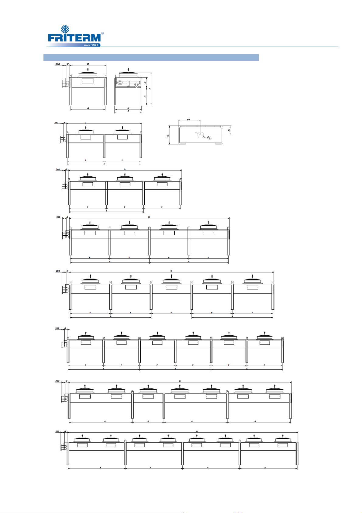
40
FDH 2E 1 Sıra Fanlı/ 1 Row Fan TEKNİK ÇİZİM •
Ø800
Ø910
11
Montaj ayağı detayı/ Mounting leg detail
Ø800
Ø910
12
Ø800
Ø910
13
Ø800
Ø910
14
Ø800
Ø910
15
Ø800
Ø910
16
Ø800
Ø910
17
Ø800
Ø910
18
Rev. Tarihi:25.05.2016 Rev.No:9 Dok. No: KLV.004.ENG
Page 44
41
Ø910
FDH 2E 2 Sıra Fanlı/2 Row Fans TEKNİK ÇİZİM •
Ø800
21
Ø800
Ø910
22
Ø800
Ø910
23
Ø800
Ø910
24
Ø800
Ø910
25
Ø800
Ø910
26
Ø800
Ø910
27
Ø800
Ø910
28
Rev. Tarihi:25.05.2016 Rev.No:9 Dok. No: KLV.004.ENG
Page 45
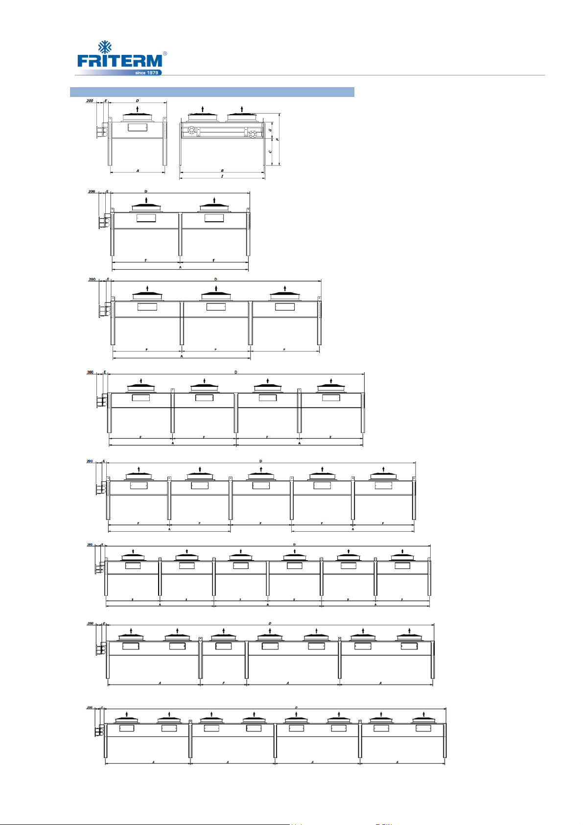
42
FDV 2E 1 Sıra Fanlı/ 1 Row Fan TEKNİK ÇİZİM • DRAWING
Ø800
Ø910
11
Ø800
Ø910
12
Ø800
Ø910
13
Ø800
Ø910
14
Ø800
Ø910
15
Ø800
Ø910
16
Ø800
Ø910
17
Ø800
Ø910
18
Rev. Tarihi:25.05.2016 Rev.No:9 Dok. No: KLV.004.ENG
Page 46
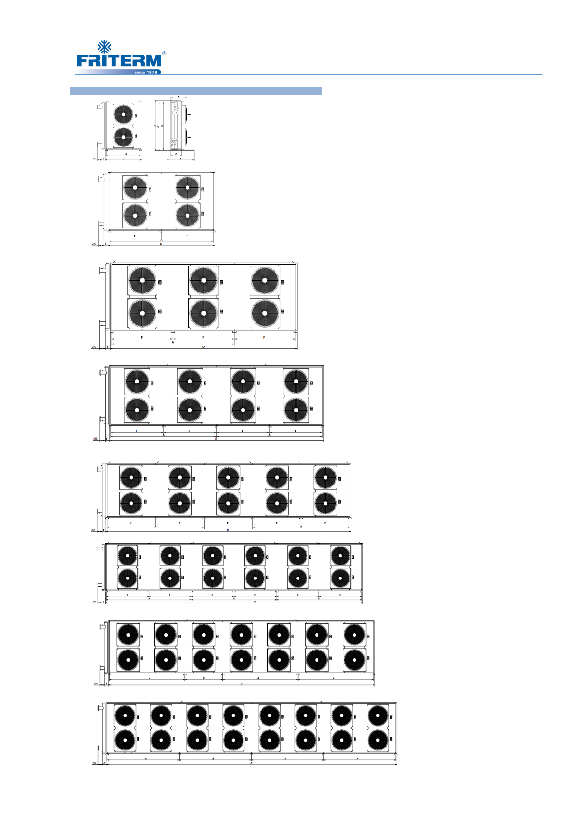
FDV 2E 2 Sıra Fanlı/2 Row Fans TEKNİK ÇİZİM • DRAWING
43
Ø800
Ø910 21
Ø800
Ø910 22
Ø800
Ø910 23
Ø800
Ø910 24
Ø800
Ø910 25
Ø800
Ø910 26
Ø800
Ø910 27
Ø800
Ø910 28
Rev. Tarihi:25.05.2016 Rev.No:9 Dok. No: KLV.004.ENG
Page 47
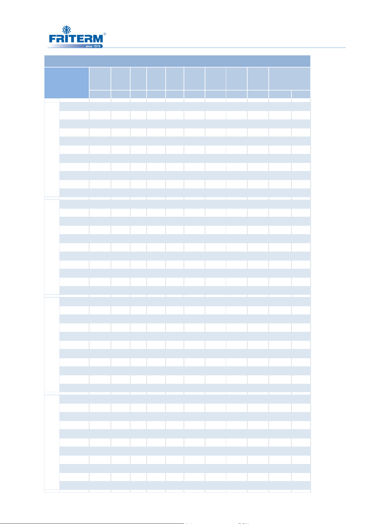
44
mmmmmmmmmmmmmmmmmm
YATIK
DİK
MODEL
FDH/FDV 2E BOYUTLAR • DIMENSIONS
D A F B I L M N Z
MODEL
E111 2900 2800 - 2300 2350 1275 1305 1255 1375 4 2
E211 2900 2800 - 2300 2350 1275 1305 1255 1375 4 2
E121 3300 3200 - 2300 2350 1275 1305 1255 1375 4 2
E221 3300 3200 - 2300 2350 1275 1305 1255 1375 4 2
E131 3700 3600 - 2300 2350 1275 1305 1255 1375 4 2
E231 3700 3600 - 2300 2350 1275 1305 1255 1375 4 2
80/91 12
E331 3700 3600 - 2300 2350 1275 1305 1255 1375 4 2
E241 4100 - 2000 2300 2350 1275 1305 1255 1375 6 3
E341 4100 - 2000 2300 2350 1275 1305 1255 1375 6 3
E251 4500 - 2200 2300 2350 1275 1305 1255 1375 6 3
E351 4500 - 2200 2300 2350 1275 1305 1255 1375 6 3
E111 4300 2800 1400 2300 2350 1275 1305 1255 1375 6 3
E211 4300 2800 1400 2300 2350 1275 1305 1255 1375 6 3
E121 4900 3200 1600 2300 2350 1275 1305 1255 1375 6 3
E221 4900 3200 1600 2300 2350 1275 1305 1255 1375 6 3
E131 5500 3600 1800 2300 2350 1275 1305 1255 1375 6 3
E231 5500 3600 1800 2300 2350 1275 1305 1255 1375 6 3
E331 5500 3600 1800 2300 2350 1275 1305 1255 1375 6 3
E241 6100 - 2000 2300 2350 1275 1305 1255 1375 8 4
E341 6100 - 2000 2300 2350 1275 1305 1255 1375 8 4
E251 6700 - 2200 2300 2350 1275 1305 1255 1375 8 4
E351 6700 - 2200 2300 2350 1275 1305 1255 1375 8 4
AYAK SAYILARI
E111 5700 2800 - 2300 2350 1275 1305 1255 1375 6 3
E211 5700 2800 - 2300 2350 1275 1305 1255 1375 6 3
E121 6500 3200 - 2300 2350 1275 1305 1255 1375 6 3
E221 6500 3200 - 2300 2350 1275 1305 1255 1375 6 3
E131 7300 3600 - 2300 2350 1275 1305 1255 1375 6 3
E231 7300 3600 - 2300 2350 1275 1305 1255 1375 6 3
80/91 1480/91 15 80/91 13
E331 7300 3600 - 2300 2350 1275 1305 1255 1375 6 3
E241 8100 - 2000 2300 2350 1275 1305 1255 1375 10 5
E341 8100 - 2000 2300 2350 1275 1305 1255 1375 10 5
E251 8900 - 2200 2300 2350 1275 1305 1255 1375 10 5
E351 8900 - 2200 2300 2350 1275 1305 1255 1375 10 5
E111 7100 2800 1400 2300 2350 1275 1305 1255 1375 8 4
E211 7100 2800 1400 2300 2350 1275 1305 1255 1375 8 4
E121 8100 3200 1600 2300 2350 1275 1305 1255 1375 8 4
E221 8100 3200 1600 2300 2350 1275 1305 1255 1375 8 4
E131 9100 3600 1800 2300 2350 1275 1305 1255 1375 8 4
E231 9100 3600 1800 2300 2350 1275 1305 1255 1375 8 4
E331 9100 3600 1800 2300 2350 1275 1305 1255 1375 8 4
E241 10100 - 2000 2300 2350 1275 1305 1255 1375 12 6
E341 10100 - 2200 2300 2350 1275 1305 1255 1375 12 6
E251 11100 - 2200 2300 2350 1275 1305 1255 1375 12 6
E351 11100 - 2200 2300 2350 1275 1305 1255 1375 12 6
Rev. Tarihi:25.05.2016 Rev.No:9 Dok. No: KLV.004.ENG
Page 48

45
E111 8500 2800 - 2300 2350 1275 1305 1255 1375 8 4
E211 8500 2800 - 2300 2350 1275 1305 1255 1375 8 4
E121 9700 3200 - 2300 2350 1275 1305 1255 1375 8 4
E221 9700 3200 - 2300 2350 1275 1305 1255 1375 8 4
E131 10900 3600 - 2300 2350 1275 1305 1255 1375 8 4
80/91 1680/91 1780/91 18
E231 10900 3600 - 2300 2350 1275 1305 1255 1375 8 4
E331 10900 3600 - 2300 2350 1275 1305 1255 1375 8 4
E241 12100 - 2000 2300 2350 1275 1305 1255 1375 14 7
E341 12100 - 2000 2300 2350 1275 1305 1255 1375 14 7
E111 9900 2800 1400 2300 2350 1275 1305 1255 1375 10 5
E211 9900 2800 1400 2300 2350 1275 1305 1255 1375 10 5
E121 11300 3200 1600 2300 2350 1275 1305 1255 1375 10 5
E221 11300 3200 1600 2300 2350 1275 1305 1255 1375 10 5
E131 12700 3600 1800 2300 2350 1275 1305 1255 1375 10 5
E231 12700 3600 1800 2300 2350 1275 1305 1255 1375 10 5
E331 12700 3600 1800 2300 2350 1275 1305 1255 1375 10 5
E111
E211 11300 2800 - 2300 2350 1275 1305 1255 1375 10 5
E121 12900 3200 - 2300 2350 1275 1305 1255 1375 10 5
E221 12900 3200 - 2300 2350 1275 1305 1255 1375 10 5
11300 2800 - 2300 2350 1275 1305 1255 1375 10 5
E C G
mm mm mm Ø800 Ø910 Ø800 Ø910
1" 70 795 480 1540 1580 740 780
1 1/4" 80 795 480 1540 1580 740 780
1 1/2" 85 795 480 1540 1580 740 780
2" 95 795 480 1540 1580 740 780
2 1/2" 110 795 480 1540 1580 740 780
3" 125 795 480 1540 1580 740 780
4" 150 795 480 1540 1580 740 780
5" 200 895 600 1760 1800 860 900
H
K
Rev. Tarihi:25.05.2016 Rev.No:9 Dok. No: KLV.004.ENG
Page 49
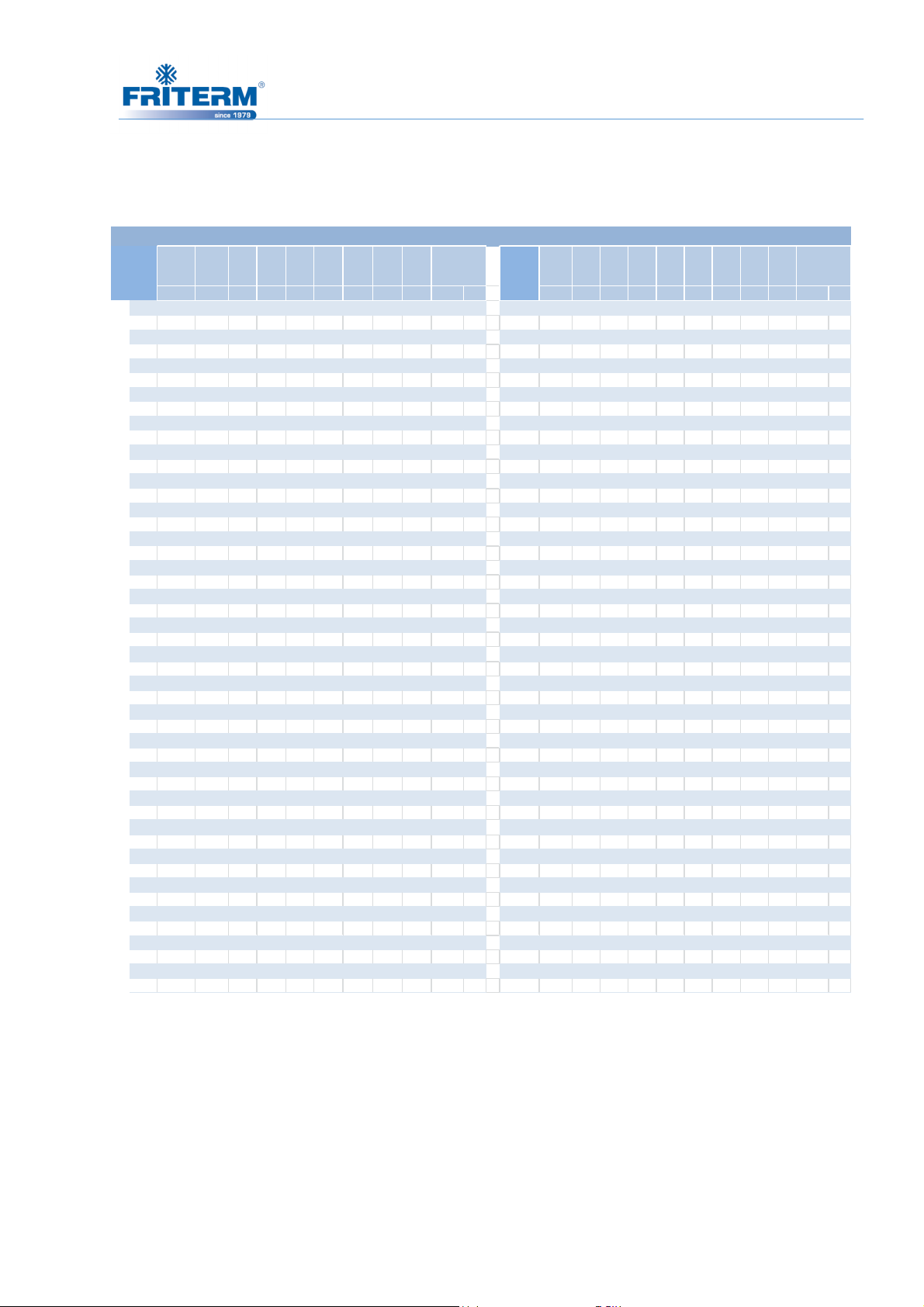
46
mmmmmmmmmmmmmmmmmm
YATIK
DİKmmmmmmmmmmmmmmmmmmYATIK
DİK
MODEL
MODEL
FDH/FDV 2E BOYUTLAR • DIMENSIONS
MODEL
D A F B I L M N Z D A F B I L M N Z
AYAK
SAYILARI
MODEL
AYAK
SAYILARI
E111
1500 1400 - 2300 2350 1275 2295 2245 2365 4 2
E211 1500 1400 - 2300 2350 1275 2295 2245 2365 4 2 E212 1500 1400 - 2450 2500 1275 2450 2400 2520 4 2
E121 1700 1600 - 2300 2350 1275 2295 2245 2365 4 2 E122 1700 1600 - 2450 2500 1275 2450 2400 2520 4 2
E221 1700 1600 - 2300 2350 1275 2295 2245 2365 4 2 E222 1700 1600 - 2450 2500 1275 2450 2400 2520 4 2
E131 1900 1800 - 2300 2350 1275 2295 2245 2365 4 2 E132 1900 1800 - 2450 2500 1275 2450 2400 2520 4 2
E231 1900 1800 - 2300 2350 1275 2295 2245 2365 4 2 E232 1900 1800 - 2450 2500 1275 2450 2400 2520 4 2
E331 1900 1800 - 2300 2350 1275 2295 2245 2365 4 2 E332 1900 1800 - 2450 2500 1275 2450 2400 2520 4 2
E241 2100 2000 - 2300 2350 1275 2295 2245 2365 4 2 E242 2100 2000 - 2450 2500 1275 2450 2400 2520 4 2
E341 2100 2000 - 2300 2350 1275 2295 2245 2365 4 2 E342 2100 2000 - 2450 2500 1275 2450 2400 2520 4 2
E251 2300 2200 - 2300 2350 1275 2295 2245 2365 4 2 E252 2300 2200 - 2450 2500 1275 2450 2400 2520 4 2
E351 2300 2200 - 2300 2350 1275 2295 2245 2365 4 2 E352 2300 2200 - 2450 2500 1275 2450 2400 2520 4 2
E111
2900 2800 - 2300 2350 1275 2295 2245 2365 4 2
E211 2900 2800 - 2300 2350 1275 2295 2245 2365 4 2 E212 2900 2800 - 2450 2500 1275 2450 2400 2520 4 2
E121 3300 3200 - 2300 2350 1275 2295 2245 2365 4 2 E122 3300 3200 - 2450 2500 1275 2450 2400 2520 4 2
E221 3300 3200 - 2300 2350 1275 2295 2245 2365 4 2 E222 3300 3200 - 2450 2500 1275 2450 2400 2520 4 2
E131 3700 3600 - 2300 2350 1275 2295 2245 2365 4 2 E132 3700 3600 - 2450 2500 1275 2450 2400 2520 4 2
E231 3700 3600 - 2300 2350 1275 2295 2245 2365 4 2 E232 3700 3600 - 2450 2500 1275 2450 2400 2520 4 2
80/ 91 2280/ 91 2380/ 91 24 80/ 91 21
E331 3700 3600 - 2300 2350 1275 2295 2245 2365 4 2 E332 3700 3600 - 2450 2500 1275 2450 2400 2520 4 2
E241 4100 - 2000 2300 2350 1275 2295 2245 2365 6 3 E242 4100 - 2000 2450 2500 1275 2450 2400 2520 6 3
E341 4100 - 2000 2300 2350 1275 2295 2245 2365 6 3 E342 4100 - 2000 2450 2500 1275 2450 2400 2520 6 3
E251 4500 - 2200 2300 2350 1275 2295 2245 2365 6 3 E252 4500 - 2200 2450 2500 1275 2450 2400 2520 6 3
E351 4500 - 2200 2300 2350 1275 2295 2245 2365 6 3 E352 4500 - 2200 2450 2500 1275 2450 2400 2520 6 3
E111
E211 4300 2800 1400 2300 2350 1275 2295 2245 2365 6 3 E212 4300 2800 1400 2450 2500 1275 2450 2400 2520 6 3
E121 4900 3200 1600 2300 2350 1275 2295 2245 2365 6 3 E122 4900 3200 1600 2450 2500 1275 2450 2400 2520 6 3
E221 4900 3200 1600 2300 2350 1275 2295 2245 2365 6 3 E222 4900 3200 1600 2450 2500 1275 2450 2400 2520 6 3
E131 5500 3600 1800 2300 2350 1275 2295 2245 2365 6 3 E132 5500 3600 1800 2450 2500 1275 2450 2400 2520 6 3
E231 5500 3600 1800 2300 2350 1275 2295 2245 2365 6 3 E232 5500 3600 1800 2450 2500 1275 2450 2400 2520 6 3
E331 5500 3600 1800 2300 2350 1275 2295 2245 2365 6 3 E332 5500 3600 1800 2450 2500 1275 2450 2400 2520 6 3
E241 6100 - 2000 2300 2350 1275 2295 2245 2365 8 4 E242 6100 - 2000 2450 2500 1275 2450 2400 2520 8 4
E341 6100 - 2000 2300 2350 1275 2295 2245 2365 8 4 E342 6100 - 2000 2450 2500 1275 2450 2400 2520 8 4
E251 6700 - 2200 2300 2350 1275 2295 2245 2365 8 4 E252 6700 - 2200 2450 2500 1275 2450 2400 2520 8 4
E351 6700 - 2200 2300 2350 1275 2295 2245 2365 8 4 E352 6700 - 2200 2450 2500 1275 2450 2400 2520 8 4
- -
4300 2800 1400 2300 2350 1275 2295 2245 2365 6 3
E112
1500 1400 - 2450 2500 1275 2450 2400 2520 4 2
E112
2900 2800 - 2450 2500 1275 2450 2400 2520 4 2
E112
4300 2800 1400 2450 2500 1275 2450 2400 2520 6 3
E111
5700 2800 - 2300 2350 1275 2295 2245 2365 6 3
E211 5700 2800 - 2300 2350 1275 2295 2245 2365 6 3 E212 5700 2800 - 2450 2500 1275 2450 2400 2520 6 3
E121 6500 3200 - 2300 2350 1275 2295 2245 2365 6 3 E122 6500 3200 - 2450 2500 1275 2450 2400 2520 6 3
E221 6500 3200 - 2300 2350 1275 2295 2245 2365 6 3 E222 6500 3200 - 2450 2500 1275 2450 2400 2520 6 3
E131 7300 3600 - 2300 2350 1275 2295 2245 2365 6 3 E132 7300 3600 - 2450 2500 1275 2450 2400 2520 6 3
E231 7300 3600 - 2300 2350 1275 2295 2245 2365 6 3 E232 7300 3600 - 2450 2500 1275 2450 2400 2520 6 3
E331 7300 3600 - 2300 2350 1275 2295 2245 2365 6 3 E332 7300 3600 - 2450 2500 1275 2450 2400 2520 6 3
E241 8100 - 2000 2300 2350 1275 2295 2245 2365 10 5 E242 8100 - 2000 2450 2500 1275 2450 2400 2520 10 5
E341 8100 - 2000 2300 2350 1275 2295 2245 2365 10 5 E342 8100 - 2000 2450 2500 1275 2450 2400 2520 10 5
E251 8900 - 2200 2300 2350 1275 2295 2245 2365 10 5 E252 8900 - 2200 2450 2500 1275 2450 2400 2520 10 5
E351 8900 - 2200 2300 2350 1275 2295 2245 2365 10 5 E352 8900 - 2200 2450 2500 1275 2450 2400 2520 10 5
E112
5700 2800 - 2450 2500 1275 2450 2400 2520 6 3
Rev. Tarihi:25.05.2016 Rev.No:9 Dok. No: KLV.004.ENG
Page 50
47
E111
7100 2800 1400 2300 2350 1275 2295 2245 2365 8 4
E211 7100 2800 1400 2300 2350 1275 2295 2245 2365 8 4 E212 7100 2800 1400 2450 2500 1275 2450 2400 2520 8 4
E121 8100 3200 1600 2300 2350 1275 2295 2245 2365 8 4 E122 8100 3200 1600 2450 2500 1275 2450 2400 2520 8 4
E221 8100 3200 1600 2300 2350 1275 2295 2245 2365 8 4 E222 8100 3200 1600 2450 2500 1275 2450 2400 2520 8 4
E131 9100 3600 1800 2300 2350 1275 2295 2245 2365 8 4 E132 9100 3600 1800 2450 2500 1275 2450 2400 2520 8 4
E231 9100 3600 1800 2300 2350 1275 2295 2245 2365 8 4 E232 9100 3600 1800 2450 2500 1275 2450 2400 2520 8 4
E331 9100 3600 1800 2300 2350 1275 2295 2245 2365 8 4 E332 9100 3600 1800 2450 2500 1275 2450 2400 2520 8 4
80/ 91 2580/ 91 2680/ 91 27
E241 10100 - 2000 2300 2350 1275 2295 2245 2365 12 6 E242 10100 - 2000 2450 2500 1275 2450 2400 2520 12 6
E341 10100 - 2200 2300 2350 1275 2295 2245 2365 12 6 E342 10100 - 2200 2450 2500 1275 2450 2400 2520 12 6
E251 11100 - 2200 2300 2350 1275 2295 2245 2365 12 6 E252 11100 - 2200 2450 2500 1275 2450 2400 2520 12 6
E351 11100 - 2200 2300 2350 1275 2295 2245 2365 12 6 E352 11100 - 2200 2450 2500 1275 2450 2400 2520 12 6
E112
7100 2800 1400 2450 2500 1275 2450 2400 2520 8 4
E111
8500 2800 - 2300 2350 1275 2295 2245 2365 8 4
E211 8500 2800 - 2300 2350 1275 2295 2245 2365 8 4 E212 8500 2800 - 2450 2500 1275 2450 2400 2520 8 4
E121 9700 3200 - 2300 2350 1275 2295 2245 2365 8 4 E122 9700 3200 - 2450 2500 1275 2450 2400 2520 8 4
E221 9700 3200 - 2300 2350 1275 2295 2245 2365 8 4 E222 9700 3200 - 2450 2500 1275 2450 2400 2520 8 4
E131 10900 3600 - 2300 2350 1275 2295 2245 2365 8 4 E132 10900 3600 - 2450 2500 1275 2450 2400 2520 8 4
E231 10900 3600 - 2300 2350 1275 2295 2245 2365 8 4 E232 10900 3600 - 2450 2500 1275 2450 2400 2520 8 4
E331 10900 3600 - 2300 2350 1275 2295 2245 2365 8 4 E332 10900 3600 - 2450 2500 1275 2450 2400 2520 8 4
E241 12100 - 2000 2300 2350 1275 2295 2245 2365 14 7 E242 12100 - 2000 2450 2500 1275 2450 2400 2520 14 7
E341 12100 - 2000 2300 2350 1275 2295 2245 2365 14 7 E342 12100 - 2000 2450 2500 1275 2450 2400 2520 14 7
E111
9900 2800 1400 2300 2350 1275 2295 2245 2365 10 5
E211 9900 2800 1400 2300 2350 1275 2295 2245 2365 10 5 E212 9900 2800 1400 2450 2500 1275 2450 2400 2520 10 5
E121 11300 3200 1600 2300 2350 1275 2295 2245 2365 10 5 E122 11300 3200 1600 2450 2500 1275 2450 2400 2520 10 5
E221 11300 3200 1600 2300 2350 1275 2295 2245 2365 10 5 E222 11300 3200 1600 2450 2500 1275 2450 2400 2520 10 5
E131 12700 3600 1800 2300 2350 1275 2295 2245 2365 10 5 E132 12700 3600 1800 2450 2500 1275 2450 2400 2520 10 5
E231 12700 3600 1800 2300 2350 1275 2295 2245 2365 10 5 E232 12700 3600 1800 2450 2500 1275 2450 2400 2520 10 5
E331 12700 3600 1800 2300 2350 1275 2295 2245 2365 10 5 E332 12700 3600 1800 2450 2500 1275 2450 2400 2520 10 5
E111 11300 2800 - 2300 2350 1275 2295 2245 2365 10 5 E112 11300 2800 - 2450 2500 1275 2450 2400 2520 10 5
E211 11300 2800 - 2300 2350 1275 2295 2245 2365 10 5 E212 11300 2800 - 2450 2500 1275 2450 2400 2520 10 5
E121 12900 3200 - 2300 2350 1275 2295 2245 2365 10 5 E122 12900 3200 - 2450 2500 1275 2450 2400 2520 10 5
80/ 91 28
E221 12900 3200 - 2300 2350 1275 2295 2245 2365 10 5 E222 12900 3200 - 2450 2500 1275 2450 2400 2520 10 5
E C G
mm mm mm Ø800 Ø910 Ø800 Ø910
1" 70 795 480 1540 1580 740 780
1 1/4" 80 795 480 1540 1580 740 780
1 1/2" 85 795 480 1540 1580 740 780
2" 95 795 480 1540 1580 740 780
2 1/2" 110 795 480 1540 1580 740 780
3" 125 795 480 1540 1580 740 780
4" 150 795 480 1540 1580 740 780
5" 200 895 600 1760 1800 860 900
H K
E112
8500 2800 - 2450 2500 1275 2450 2400 2520 8 4
E112
9900 2800 1400 2450 2500 1275 2450 2400 2520 10 5
Rev. Tarihi:25.05.2016 Rev.No:9 Dok. No: KLV.004.ENG
Page 51
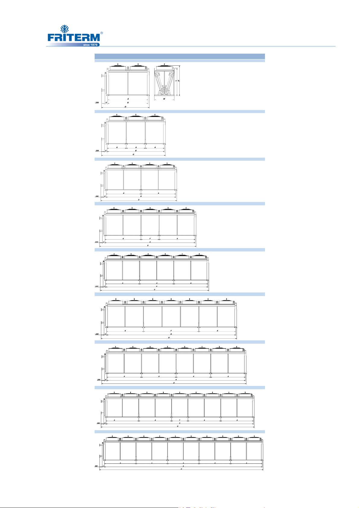
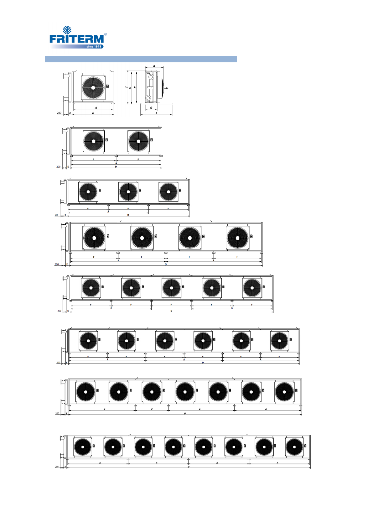
48
FDW 1 Sıra 4 Fan (1 Row 4 Fans)
FDW 1 Sıra 2 Fan (1 Row 2 Fans)
FDW 2E
TEKNİK
FDW 1 Sıra 3 Fan (1 Row 3 Fans)
FDW 1 Sıra 5 Fan (1 Row 5 Fans)
FDW 1 Sıra 6 Fan (1 Row 6 Fans)
FDW 1 Sıra 7 Fan (1 Row 7 Fans)
FDW 1 Sıra 8 Fan (1 Row 8 Fans)
FDW 1 Sıra 9 Fan (1 Row 9 Fans)
FDW 1 Sıra 10 Fan (1 Row 10 Fans)
Rev. Tarihi:25.05.2016 Rev.No:9 Dok. No: KLV.004.ENG
Page 52
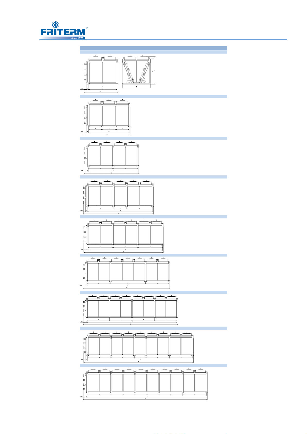
49
FDW 2E
TEKNİK
FDW 2 Sıra 2 Fan (2 Row 2 Fans)
FDW 2 Sıra 3 Fan (2 Row 3 Fans)
FDW 2 Sıra 4 Fan (2 Row 4 Fans)
FDW 2 Sıra 5 Fan (2 Row 5 Fans)
FDW 2 Sıra 6 Fan (2 Row 6 Fans)
FDW 2 Sıra 7 Fan (2 Row 7 Fans)
FDW 2 Sıra 8 Fan (2 Row 8 Fans)
FDW 2 Sıra 9 Fan (2 Row 9 Fans)
FDW 2 Sıra 10 Fan (2 Row 10 Fans)
Rev. Tarihi:25.05.2016 Rev.No:9 Dok. No: KLV.004.ENG
Page 53
50
EWL
E111
7200
2400-7330
2290
2330
2165
mmmmØ800
Ø910mmE211
7200
2400-7330
2290
2330
2165
mmmmE111
9600
2400-9730
2290
2330
2165
MODEL
MODEL
H
FDW 2E BOYUTLAR • DIMENSIONS
B A F D B A F D H(Ø800) H(Ø910) L
mm mm mm mm mm mm mm mm mm mm mm
80/91 22
80/91 2380/91 15
80/91 24
MODEL
E311 2400 2400 - 2530 2290 2330 2165
E312 2400 2400 - 2530 2710 2750 2590
E211 3600 1200 - 3730 2290 2330 2165
E212 3600 1200 - 3730 2710 2750 2590
E111 4800 2400 - 4930 2290 2330 2165
E112 4800 2400 - 4930 2710 2750 2590
80/91 12
80/91 13
80/91 14
80/91 16
80/91 17
80/91 18
MODEL
E111 2400 2400 - 2530 E111 2400 2400 - 2530 2290 2330 2165
E211 2400 2400 - 2530 E211 2400 2400 - 2530 2290 2330 2165
E111 3600 1200 - 3730 E112 2400 2400 - 2530 2710 2750 2590
E211 3600 1200 - 3730 E212 2400 2400 - 2530 2710 2750 2590
E111 4800 2400 - 4930
E211 4800 2400 - 4930 E111 3600 1200 - 3730 2290 2330 2165
E111 6000 2400 1200 6130 E311 3600 1200 - 3730 2290 2330 2165
E211 6000 2400 1200 6130 E112 3600 1200 - 3730 2710 2750 2590
E111 7200 2400 - 7330 E312 3600 1200 - 3730 2710 2750 2590
E211 7200 2400 - 7330
E111 8400 2400 3600 8530 E211 4800 2400 - 4930 2290 2330 2165
E211 8400 2400 3600 8530 E311 4800 2400 - 4930 2290 2330 2165
E111 9600 2400 - 9730 E212 4800 2400 - 4930 2710 2750 2590
E211 9600 2400 - 9730 E312 4800 2400 - 4930 2710 2750 2590
80/91 19
80/91 110
E111 10800 2400 1200 10930 E111 6000 2400 1200 6130 2290 2330 2165
E211 10800 2400 1200 10930 E211 6000 2400 1200 6130 2290 2330 2165
E111 12000 2400 - 12130 E112 6000 2400 1200 6130 2710 2750 2590
E211 12000 2400 - 12130 E212 6000 2400 1200 6130 2710 2750 2590
Mani fold
Dia meter
1" 120 1185 2110 1580 1650 E311 7200 2400 - 7330 2290 2330 2165
1 1/4" 130 1185 2110 1580 1650 E112 7200 2400 - 7330 2710 2750 2590
1 1/2" 135 1185 2110 1580 1650 E212 7200 2400 - 7330 2710 2750 2590
2" 145 1185 2110 1580 1650 E312 7200 2400 - 7330 2710 2750 2590
2 1/2" 160 1185 2110 1580 1650
3" 175 1185 2110 1580 1650 E111 8400 2400 3600 8530 2290 2330 2165
4" 200 1185 1540 1580 1650 E211 8400 2400 3600 8530 2290 2330 2165
5" 250 1185 1760 1800 1650 E311 8400 2400 3600 8530 2290 2330 2165
Mani fold
Dia meter
1" 120 2365 E211 9600 2400 - 9730 2290 2330 21165
1 1/4" 130 2365 E311 9600 2400 - 9730 2290 2330 2165
1 1/2" 135 2365 E112 9600 2400 - 9730 2710 2750 2590
2" 145 2365 E212 9600 2400 - 9730 2710 2750 2590
2 1/2" 160 2365 E312 9600 2400 - 9730 2710 2750 2590
3" 175 2365
4" 200 2365 E111 10800 2400 1200 10930 2290 2330 2165
5" 250 2365 E211 10800 2400 1200 10930 2290 2330 2165
E W
80/91 25
80/91 26
80/91 27
80/91 28
80/91 29
E311 6000 2400 1200 6130 2290 2330 2165
E312 6000 2400 1200 6130 2710 2750 2590
E112 8400 2400 3600 8530 2710 2750 2590
E212 8400 2400 3600 8530 2710 2750 2590
E312 8400 2400 3600 8530 2710 2750 2590
E311 10800 2400 1200 10930 2290 2330 2165
E112 10800 2400 1200 10930 2710 2750 2590
E212 10800 2400 1200 10930 2710 2750 2590
E312 10800 2400 1200 10930 2710 2750 2590
E111 12000 2400 - 12130 2290 2330 2165
E211 12000 2400 - 12130 2290 2330 2165
80/91 210
E311 12000 2400 - 12130 2290 2330 2165
E112 12000 2400 - 12130 2710 2750 2590
E212 12000 2400 - 12130 2710 2750 2590
E312 12000 2400 - 12130 2710 2750 2590
Rev. Tarihi:25.05.2016 Rev.No:9 Dok. No: KLV.004.ENG
Page 54
51
6.4 Electrical Connection
The electrical connection must comply with the relevant instructions and ground wires must
be installed correctly.
• The fan speed control could be managed by implementing the FMM (Friterm Motor
Management) system.
• The wiring of fans should be done in accordance with the related rules.
• The main power supply cable should be determined according to the electrical power
requirements of the product specified on the label.
• A protection thermal relay should be used where absent for the operational protection
of the fan.
•
Electrical wiring connetions/junctions should be under protection with minimum IP54
class boxes.
Risk of injury by electric shock
When connecting the electronic control to the power supply, injuries by electric shock are
possible because of the voltage supply.
• All electrical connections on the product must be made by a qualified electrician in
accordance with the electrical engineering rules.
The main power switch should be turned off unless needed before the a repairing/maintenance
action.
The electrical connection must not be done unless the legs are mounted.
Given nuts, bolts and spangles, must be completely used for mounting.
For the horizontal (H) type mounting:
• The product must be fixed with 4 lifting eyes, afterwards must be lifted approximately
1m so as to begin leg mounting.
• Use two spangles and a nut for each bolt while leg mounting.
• Be sure that all legs are equally far away from the surface
Rev. Tarihi:25.05.2016 Rev.No:9 Dok. No: KLV.004.ENG
Page 55

52
• Lower down the product slowly.
• The position control must be maintained with a water gauge on the product. The dry
cooler must be positioned parallel to the surface.
• Fix the product to the surface.
For the vertical (V) type mounting:
• Fix the product with 2 lifting eyes and afterwards begin foot mounting.
• Use 2 spangles and a nut for each bolt must be used.
• Lower down the product slowly.
• The position control must be maintained with a water gauge placed on the product. The
product must be positioned parallel to the surface.
• Fix the product to the surface.
7. OPERATION
7.1 Initial commissioning
Before running the unit for the first time, be sure that all guards, motor mountings and
electrical covers are secure, installation and electrical connection are done properly, internal
wiring is kept away from the fans and the fans can rotate freely.
Make sure that all the mechanical connections are done in accordance with the rules. Piping is
consistent with the guidelines. Before the start-up you may run the fans individually to make
sure that they are running properly. Turn on the fluid valves and let the fluid flow right before
running the fans. In case you may encounter any problem or disfunction please refer to the
manufacturer for the resolution of the problem.
7.2 Regular commissioning
If the product is stationary for long periods in a humid atmosphere, the fans must be switched
ON for minimum of four hours in every month to remove any moisture that may have
condensed within the motors.
While the fans are running, anything that could pass through the finger guards, like a piece of
cloth or long hair, must be kept away from the fans.
• Switch on the main power switch
• Make sure that the fluid is flowing inside the pipes.
Rev. Tarihi:25.05.2016 Rev.No:9 Dok. No: KLV.004.ENG
Page 56
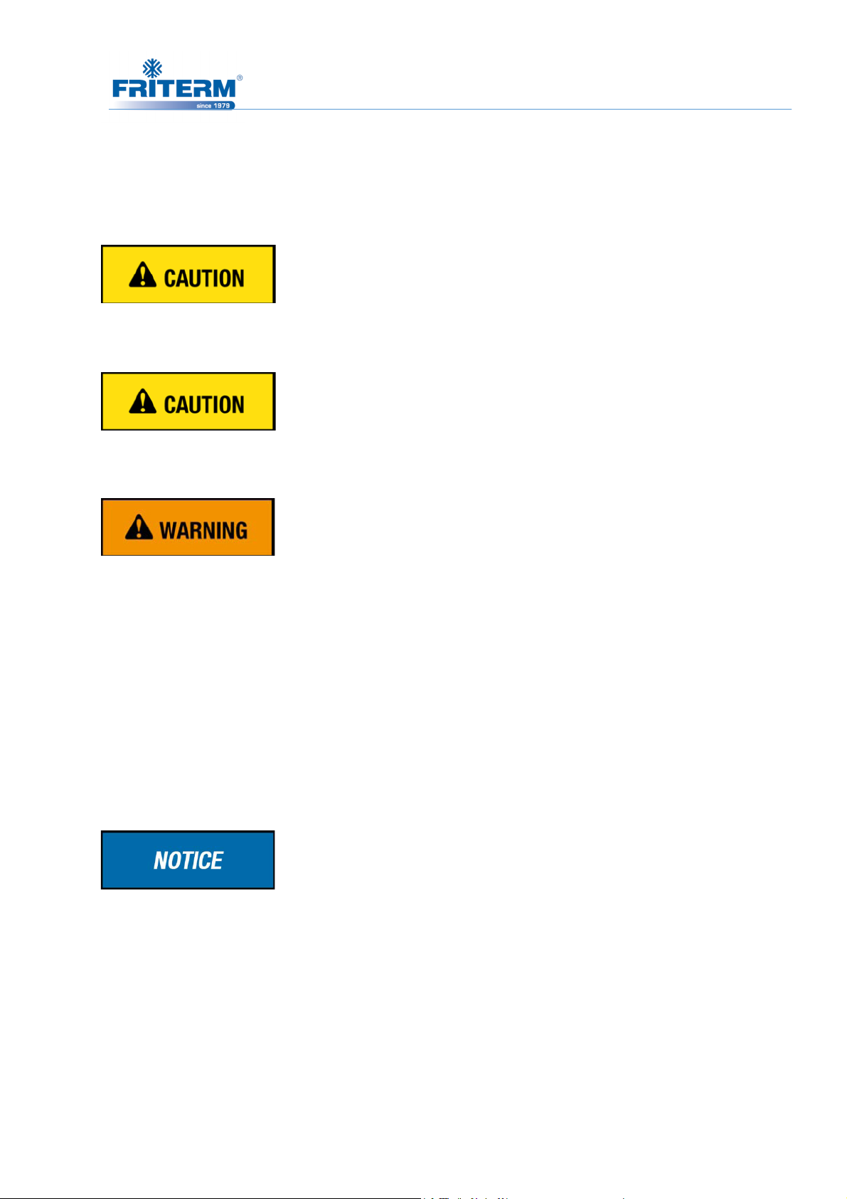
53
• Switch on the fans.
7.3 Shutting down
Fan connection must be disconnected and working fluid circulation must be stopped to shut
the product down.
After shutting the unit down the operating pressure must be observed whether the
operating pressure exceeds maximum operating pressure or not.
Stay away from the air direction of the fans while the fans are running.
Before touching, it is recommended to ensure that the headers and the connection pipes
are neither too hot nor too cold due to working conditions of the fluid inside.
The operation must be stopped and the supplier must be informed in case of any unusual
working condition, such as abnormal operating noise. Intensive vibrations due to out-of-
balance running of the fans may lead to outage.
Maintenance must not be performed while the product is in use (See part 8 for details).
As it is not possible to evacuate fluid fully, antifreeze must be added to product for safety.
(See part 8 for details)
Recommended starting value for fans is 6 per hour while maximum is 10.
7.4 Step control application (If Applicable)
In step controlled applications; the fan groups that will be working and not working must be
arranged according to scheme given below which is defined as “TRUE”. Otherwise the
problems given below will be observed:
1. The air will not be fully absorbed from by the fans. Hence the efficiency will decrease.
Rev. Tarihi:25.05.2016 Rev.No:9 Dok. No: KLV.004.ENG
Page 57
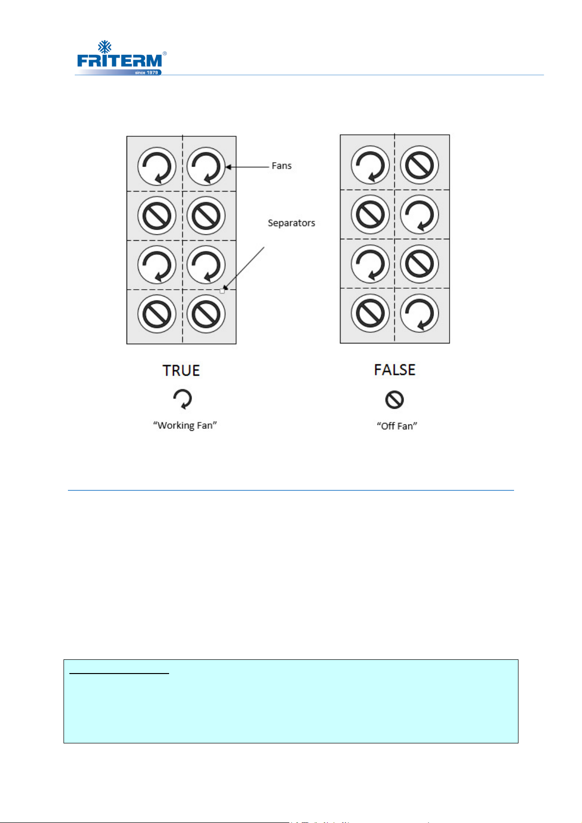
54
2. When a fan is taken into the circuit which rotates in contrary directions, the fan will be
damaged because of constriction.
8. MAINTENANCE
8.1 Maintenance intervals
Maintenance operation is to be performed by qualified personnel only. Please be sure that
safety regulations and the worker's protection rules are obeyed during the maintenance and
service (DIN EN 50110).
The fluid circulation must be stopped and it must be ensured that no electrical supply
connection exists during maintenance. It is advisable to wait till the product comes to thermal
balance with its surroundings if possible.
Freezing Protection; Since it is not possible to drain all of liquid from the system, dry
coolers have freezing threaten. Therefore fluid must be protected against freezing by
adding adequately amount of antifreeze to the fluid. On the other hand, quantity of
added antifreeze must be checked whether it decreases or not.
Rev. Tarihi:25.05.2016 Rev.No:9 Dok. No: KLV.004.ENG
Page 58
55
ATTENTION !!! It must be chosen 7-10 °C lower temperature in order to provide safely
antifreeze (glycol) ratio.
Mixture Freezing Points For Different Antifreeze Ratios
Volumetric Mixing Ratio
%100 Water 0 °C
% 80 Water + % 20 Glycol -7 °C
% 70 Water + % 30 Glycol -14 °C
% 60 Water + % 40 Glycol -22 °C
% 50 Water + % 50 Glycol -33 °C
% 40 Water + % 60 Glycol -48 °C
Reference: ASHRAE
Freezing
Temperature
If the tubes within the product or the connection pipes are to be repaired, the fluid in the line
must be drained beforehand.
8.2 Fan motor maintenance
• Regarding the bearings, the fans are maintenance-free for 30000-40000 hours under
normal operating conditions. Lifetime lubrication is not necessary within this period,
and when this period expires or the bearings are damaged, it is necessary to replace the
bearings with original parts.
• If the fans are to be maintained, the instruction manual prepared by the fan
manufacturer must be followed. Please contact manufacturer when needed.
• After maintenance is performed, ensure that no tools or other foreign materials are left
in or near the product.
Rev. Tarihi:25.05.2016 Rev.No:9 Dok. No: KLV.004.ENG
Page 59

56
Follow to Initial Commissioning before operating the product after maintenance.
8.3 Periodical controls (Once a year)
• Corrosion on the fins and tubes should be inspected. If the tubes are worn-out, leakage
may occur.
• The pipeline must be controlled for damage and leakage.
• Mechanical and electrical connections of the fans must be checked. Fans must be able
to rotate freely and finger guard must be stable.
• All the fixings, especially fan motor mountings and product installation fixings must
be ensured to be secure.
8.4 Clean up
Cleaning the fins
• One of the effective method to clean up the fins is to spray pressurized air. This
action should be conducted after stoppig the fans and turning off the fluid supply
valves. The air jet should be provided to be parallel to the fins for the best cleaning
results.
• Fins could also be cleaned up by pressurized water jet. The water jet should be
provided to be pararllel to the fins for best result. . This action should be conducted
after stoppig the fans and turning off the fluid supply valves. The cleaning action
should be carried out inside-out. Some harmless solvent/detergents could be added
to the water to ease the removal of hardened dirt. Any known corrosive/abressive
chemichal should be avoided to be used in cleaning action.
• The wiring and fans should not be wetted during the cleaning process.
Celaning up the Fans
• Fans should be cleaned with the aid of pressurized air and a soft brush.
Rev. Tarihi:25.05.2016 Rev.No:9 Dok. No: KLV.004.ENG
Page 60
9.
TROUBLESHOOTING
Faults
Fans are not running properly
Polluted coils
Different brine working pressure
Fan blade stuck
Power supply cut off
Fan blades defect
Parts of carrying refrigerant
are leaking
Rev.No:9 Dok. No: KLV.004.ENG
Causes
Repair or change fans
Adjust brine pressurising values to reference
rotate freely
er supply
Modify or change fan blades
Turn off the fans and
Treatment
57
Insufficient Capacity
Fan motor is not
working
Vibration
Fluid Leakage
Clean
values
Enable fan to
Fix pow
tools
prevent leakage
refrigerant feed,
Rev. Tarihi:25.05.2016
 Loading...