

Fristam Pumps PM Series, PM 01, PM 05, PM 04, PM 02 Original Instructions Manual
...
Original Instructions
Powder Mixer
PM
Powder Mixer Size:
Powder Mixer No.:

Copyright
© Copyright 2010 Fristam Pumpen KG (GmbH & Co.)
All rights reserved. The contents, including graphic images and layout of this
operating instructions manual are subject to copyright protection and to other
laws for the protection of intellectual property. The publication and modification
of the contents are not authorised. Moreover, you may not copy, publish and alter
the contents therein for commercial purposes, or transmit the information to a
third party.
The German version is the original version of the operating instructions manual. Other languages are translations of the original operating manual.

Table of contents
1 Introduction .......................................................... 5
1.1 Foreword.................................................................. 5
1.2 Manufacturer.......................................................... 5
1.3 Scope of Supply..................................................... 5
1.4 Scope of Documentation................................... 5
1.5 General Information............................................. 6
1.6 Display Conventions............................................ 6
2 Safety........................................................................ 7
2.1 Intended Use .......................................................... 7
2.2 Predictable Misuse................................................ 7
2.3 System-Specific Safety Instructions ............... 7
2.4 Labels ........................................................................ 8
2.5 Noise Emissions ..................................................... 9
2.6 Disposal .................................................................... 10
3 Design and Function......................................... 11
3.1 Principles of Design.............................................. 11
3.2 Funnel ....................................................................... 11
3.3 Pipes........................................................................... 12
3.4 Pumps ....................................................................... 13
3.5 Control Cabinet ..................................................... 13
3.6 Vibratory Motor (Optional)................................ 14
3.7 Screen (Optional) .................................................. 15
3.8 Protective Grating (Optional) ........................... 15
3.9 Sizes and Standard Equipment........................ 16
3.10 Hydraulic Diagram................................................ 17
3.11 Function ................................................................... 18
4 Transportation..................................................... 18
4.1 Safety Instructions ................................................ 18
4.2 Moving With Industrial Truck ........................... 19
4.3 Moving With Crane............................................... 19
6 Installation ............................................................. 20
6.1 Safety Instructions................................................. 20
6.2 Installation Location............................................. 20
6.3 Reduction of Noise and Vibration.................... 21
6.4 Powder Mixer Fixation......................................... 21
6.5 Installation of Pipes............................................... 21
6.6 Supply System Connection................................ 22
6.7 Hydraulic Connection .......................................... 22
6.8 Connection of Power Supply............................. 23
6.9 Checking Direction of Rotation of Pumps.... 23
6.10 Cleaning.................................................................... 23
7 Operation................................................................ 24
7.1 Turning On Powder Mixer .................................. 25
7.2 Starting Powder Mixer ......................................... 25
7.3 Monitoring Operation.......................................... 26
7.4 Stopping Powder Mixer ...................................... 26
7.5 Turning Off Powder Mixer .................................. 26
8 Faults......................................................................... 27
8.1 Safety Instructions................................................. 27
9 Maintenance.......................................................... 27
9.1 Safety Instructions................................................. 27
9.2 Replacement Parts ................................................ 28
10 Appendix................................................................. 28
10.1 Specifications.......................................................... 28
10.2 Performance Overview........................................ 29
10.3 Lubricants................................................................. 30
10.4 Troubleshooting Table ........................................ 31
10.5 Maintenance Intervals ......................................... 33
10.6 EC Declaration of Conformity............................ 34
5 Storage .................................................................... 19
5.1 Safety Instructions ................................................ 19
5.2 Storage Conditions............................................... 19
5.3 Mothballing of the Powder Mixer................... 20
5.4 Recommissioning ................................................. 20
3

/ / PM POWDER MIXER / / /
4

1 Introduction
1.1 Foreword
This operator's manual describes all sizes, models, and versions of the PM powder mixer.
Information on the model, size, version, and accessories applicable to your powder mixer
can be found on the rating plate on your powder mixer and in the "Order-Related Documents" in the attached documents.
1.2 Manufacturer
FRISTAM Pumpen KG (GmbH & Co.)
Kurt-A.-Körber-Chaussee 55
21033 Hamburg
GERMANY
Tel.: +49-40 - 72556 -0
Fax: +49-40 -72556 -166
E-mail: info@fristam.de
1.3 Scope of Supply
The package includes the following items:
– Table
Height-adjustable machine legs or wheels (partially pivot)
– Funnel with external electric vibrator (vibratory motor)
optional: protective grating, screen, guard or CIP cover, screw-in bushing for fill level
sensor, filler adapter
– Centrifugal pump type Fristam FZ
optional: enclosure
– Shear pump type Fristam FSP
optional: enclosure
– Piping system with valves, inline sight glass, and connections
optional: adapter, pneumatic or electropneumatic valve drive, bypass
– Control cabinet with switches, buttons, and indicator lights
optional: frequency converter with control panel
– optional: connection cable and CEE three-phase plug in accordance with DIN EN 60309
1.4 Scope of Documentation
The documentation includes the following items:
– This operator's manual
– Powder mixer specifications
– FZ centrifugal pump operator's manual
– FSP shear pump operator's manual
– Vibratory motor operator's manual
– Brief instructions for frequency converter (optional)
5
/ / PM POWDER MIXER / / /
– Circuit diagram for control cabinet
– Order-related documents
Please read this information before installing and operating the powder mixer.
1.5 General Information
Please read this operator's manual completely before using the powder mixer and keep it
available at the mixer installation location.
Heed the applicable national regulations of the owner's country and the company's work
and safety regulations.
All work described here may only be performed by qualified experts with caution.
Danger of contamination: Heed legal and operational safety regulations when pumping or
filling dangerous media.
1.6 Display Conventions
List items are preceded by dashes:
– Part 1
– Part 2
Handling instructions that must be performed in a specified order are numbered:
1. Turn device on.
2. Turn device off.
Handling instructions that do not need to be performed in a specified order are preceded by
triangular bullets:
► Action
► Action
1.6.1 Safety Instructions
A safety instruction with the signal word "Danger" indicates personal hazards causing death
or serious injury.
A safety instruction with the signal word "Warning" indicates personal hazards that may lead
to death or serious injury.
A safety instruction with the signal word "Caution" indicates personal hazards that may lead
to mild to moderate injuries.
A safety instruction with the signal word "Note" warns of the possibility of material damage.
6

2 Safety
2.1 Intended Use
The standard PM powder mixer version is designed for use in the food, pharmaceutical, and
biotechnology industries.
The PM powder mixer is designed for blending liquid base media with powder or liquid additive media. In its standard use, the powder mixer is designed for batch mode with individual powder bags. Continuous operation utilizing conveying equipment is possible with a
special version.
Each PM powder mixer is designed according to customer requirements. The seal materials
in the pumps have been selected for the respective media.
Supply and pumping of the base medium must be done in compliance with the maximum
temperatures and pressures specified for the given powder mixer version and size. See the
attached document entitled "Specifications."
The pump flow direction for the self-priming pump is fixed. The FZ pump can generate a
vacuum in the suction line.
The PM powder mixer may only be used under the operating conditions specified in the customer's order. See the attached Order-Related Documents. For other operating conditions,
please contact Fristam.
2.2 Predictable Misuse
– The standard PM powder mixer versions may not be used in explosive atmospheres.
– Introduction and pumping of foreign objects in the mix can block and destroy the pipes,
the valves, or the shear pump.
– Pumping of base media or powders other than those specified can destroy pipes, valves,
or pumps. The seal materials (elastomers) and the pumps have been selected for specific
base media and mixtures. See Specifications and Order-Related Documents.
– Pumping of powders other than those specified or incorrect mixing ratios can clog the
pipes, the valves, or the shear pump. For uninterrupted operations, the maximum allowable particle size of the powder must not be exceeded.
– Modifications and changes to the pump are only permissible with the consent of Fristam.
2.3 System-Specific Safety Instructions
Impermissible Pressure or Temperature Range
Personal injury and material damage from leakage or bursting of pumps or pipes and valves.
► Maintain the pump, pipe, and valve pressures within the specified pressure ranges. See
the attached document entitled "Specifications" and the operator's manuals for the
pumps.
Maintain the pump and pipe temperatures within the specified temperature ranges. See the
attached document entitled "Specifications" and the operator's manuals for the pumps.
Hot Equipment Surface
Contact burns from touching the pipes.
► Check the temperature before touching the pipes.
► Only touch the pipes if you are wearing suitable gloves.
Noise Generated By Running Powder Mixer
Permanent hearing damage. The A-weighted sound pressure level of the powder mixer can
be greater than 80 dBA.
7

/ / PM POWDER MIXER / / /
► Always wear ear protectors in the vicinity of the running powder mixer.
► The local noise exposure regulations must be complied with.
► See the noise emission values for the pumps in the attached operator's manuals.
Danger of Crushing When Moving Powder Mixer on Casters
Foot injuries from being run over by casters.
► Wear safety shoes.
Cold Firefighting Water on Hot Pump
Material damage from bursting of pump.
► Do not cool the pump down excessively when extinguishing a fire.
Unsuitable Working Height or Direction
Danger of injury when working on raised table.
► Lift the powder bag using a suitable aid.
► Place a working platform beside the table and use.
► Work on the side of the table designated for this purpose.
2.4 Labels
► Do not alter or remove the labels on the powder mixer.
► Immediately replace damaged or lost labels with ones that are true to the originals.
2.4.1 Safety Labels
Fig. 1 "Hot Surface"
The "Hot Surface" label indicates that parts can become hot during operation or, if applicable, that a hot base medium is being pumped. Check the temperature before touching the
pipes. Only touch the pipes if you are wearing suitable gloves.
Fig. 2 "Do Not Reach Into Funnel"
The "Do Not Reach In" label indicates that the funnel must not be reached into during operation. There is a danger of injury in the region of the valve.
Fig. 3 "Do Not Bend Over Funnel"
The "Do Not Bend Over Funnel" label indicates that breathing in of dust or aerosols above
the funnel must be avoided. Dust and aerosols can irritate the respiratory tract. Wear a dust
mask if necessary.
Fig. 4 "Do Not Place Small Parts in Funnel"
8
The "Do Not Place Small Parts in the Funnel" label indicates that no hard objects such as
rocks or metal parts should be allowed to get into the powder mixer. If they do, valves and
pumps can be damaged or destroyed and the product will be contaminated. In an emergency, immediately press the emergency stop button and remove small parts.
Fig. 5 "Wear Ear Protectors"
The "Wear Ear Protectors" label indicate that damaging noise exposure may occur. Wear ear
protectors when operating the powder mixer.
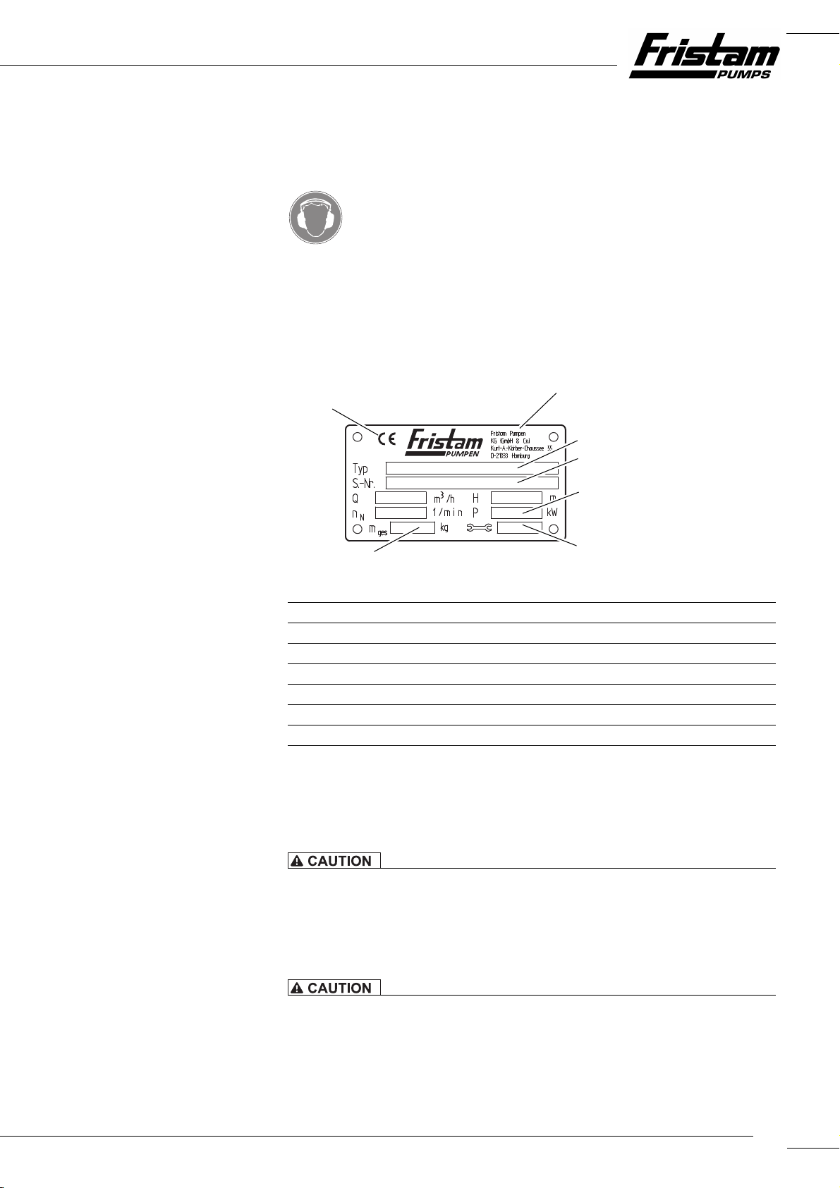
2.4.2 Rating Plate
The rating plate can be found on the lower part of the frame beside the shear pump.
1
7
2
3
4
6
Fig. 6 Rating plate
Manufacturer
1
Typ: PM powder mixer
2
S.-Nr.: serial number of the PM powder mixer
3
motor output (total) [kW]
P:
4
5
5 Year of manufacture
ttl: mass (total) [kg]
m
6
CE mark
7
2.5 Noise Emissions
The operating company must determine the respective sound pressure level for the base
media used and instruct and protect personnel accordingly.
Noise Generated by Running Pump
Hearing damage.
► The local noise exposure regulations must be complied with. For noise emission values
for the pumps, please see the pump operator's manuals.
Noise Generated by Running Vibratory Motor
Hearing damage.
► For powder mixers with two funnels or multiple vibratory motors, increased noise emis-
sions must be taken into account.
9

/ / PM POWDER MIXER / / /
Wear ear protectors when using the powder mixer with pumps or shakers with specified
sound pressure levels of greater than 80 dBA. See Chapter 10.1.2, "Noise Emissions," page 28
and the operator's manual for the vibratory motor.
2.6 Disposal
► Follow the instructions in the operator's manuals for the powder mixer components.
2.6.1 Disposal of Transportation Package
► Recycle the transportation package.
2.6.2 Disposal of Grease
► Dispose of grease and objects saturated with grease in an environmentally friendly man-
ner in accordance with applicable regulations.
2.6.3 Disposal of Lubricating Oil
► Dispose of oil and objects saturated with oil in an environmentally friendly manner in ac-
cordance with applicable regulations.
2.6.4 Disposal of Powder Mixer
1. Carefully clean the powder mixer. Dispose of residues in an environmentally friendly
manner in accordance with applicable regulations.
2. Dismantle the powder mixer into its constituent parts.
3. Dispose of the components in an environmentally friendly manner in accordance with
applicable regulations.
2.6.5 Disposal of Electrical and Electronic Scrap
► Dispose of electrical and electronic scrap in accordance with applicable directives.
10

3 Design and Function
3.1 Principles of Design
A centrifugal pump (P1), a shear pump (P2), a control cabinet, and a funnel are connected to
a pipe system in the PM powder mixer. The components are mounted to a table with a
frame. The standard funnel is equipped with a vibratory motor. The entire system is mounted on casters or legs.
17
16
89
101211
131415
Fig. 7 Powder mixer layout
Funnel, grating optional
8
Table
9
Vibratory motor
10
Self-priming pump (FZ pump, P1)
11
Control cabinet
12
Shear pump (FSP pump, P2)
13
Caster (optional)
14
Frame
15
Pipes
16
Powder inlet
17
3.2 Funnel
Powder or liquid additive media is poured into the funnel, where it is then routed to the
base medium in the pipe. The funnel is sealed in the lower region by metering valve V1. In
the standard version, a vibratory motor is mounted on the side of the funnel. Other options
such as protective grating, filter, CIP cover, screw-in bushing, and adapter are available. The
funnel can be mounted on a vibration mount or welded on.
11
/ / PM POWDER MIXER / / /
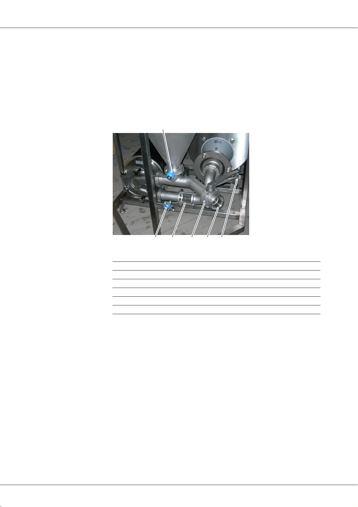
3.3 Pipes
The pipes include connections, manual and pneumatic valves, and the sight glass. Standard
manual valves are equipped with hand levers that can be locked in the 0° and 90° positions.
Other handles or attached drives can optionally be installed.
The premix, made up of the base medium and the powder or added liquid, is formed in the
pipe region between throttle valve V2 and centrifugal pump P1.
The homogeneous end product is formed in shear pump P2 upstream of the discharge-side
connection.
18
Fig. 8 Pipes, version with hand valves
Metering valve V1
18
Discharge-side connection
19
Suction-side connection
20
Throttle valve V2
21
Sight glass
22
Drain valve V3
23
21
19202223
3.3.1 Valves
The manual valves in the standard version are set as follows:
1. Pull the handle out lengthwise.
2. Rotate the lever to the desired position.
All manual disk valves in the standard version only engage in the positions "On" or "Off."
3.3.2 Variants of Metering Valve V1
Stepless Metering Valve V1
Valve V1 as a manual valve can be equipped with a continuously adjustable hand lever instead of a standard hand lever.
12
Valve Combination V1.1 + V1.2
Combination metering valve V1.1 stepless and V1.2 pneumatic (optional)
A V1.2 valve can be positioned below a V1.1 continuously adjustable manual valve. It has a
pneumatic drive and can only be set to positions "On" and "Off."
 Loading...