

Fristam Pumps FP Series, FPX Series Instruction And Maintenance Manual
Fristam FP/FPX Series Pump
INSTRUCTION AND MAINTENANCE MANUAL:
FP AND FPX SERIES Pumps (Original Instructions)
1
SANITARY CENTRIFUGAL PUMPS

Fristam FP/FPX Series Pump
2
DESCRIPTION
This manual contains installation, operation, assembly, disassembly and repair instructions for the
Fristam FP and FPX centrifugal pumps.
The heavy-duty FP pump is flange mounted on a cast flange support. This flange support provides an
extremely sturdy method of coupling the pump head and the motor. It absorbs vibrations and noise.
The flange support also fastens the pump to the floor (or adjustable base). The FP series is available
with either a single or double mechanical seal.
The general purpose FPX pump is mounted on a close coupled-style flange support. The FPX series is
only available with a single mechanical seal.
There are two general styles of pump heads in “F” type Fristam pumps. The 700 and 1700 series
are non-volute style pumps. The 1050, 1150, 3400, and 3500 series are volute style. In general,
maintenance procedures for both series are the same. Any variations will be clearly noted.
The motors used on both the FP and FPX style pumps are standard NEMA totally enclosed fan cooled
(TEFC) motors. They are C-face (except 320TSD, which are D flange - only available on FP series
pumps). Replacement motors are readily available from local motor distributors.
SAFETY
This instruction and maintenance manual shall be read and completely understood prior
to operation of the pump. The manual should be kept available at the pump installation
location.
All applicable local/national regulation and laws shall be followed.
All work described herein may only be performed by qualified personnel.
Personal protective equipment (PPE) such as hearing protection may be required.
Despite inherent safe design measures some amount residual risk will remain. Throughout
the manual these risks will be pointed out.
CAUTION: Begin all pump maintenance operations by disconnecting the
energy source to the pump. Observe all lock out/tag out procedures as outlined by ANSI Z244.1-1982 and OSHA 1910.147
!
to prevent accidental start-up and injury.

Fristam FP/FPX Series Pump
TAbLE OF CONTENTS
Safety .......................................................................................................................................2
technical information ..................................................................................................................4
recommended Preventive maintenance ........................................................................................ 5
Seal rePlacement ....................................................................................................................... 6
PumP head diSaSSembly .................................................................................................. 6
additional diSaSSembly for double mechanical SealS (fP only) ....................................7
PumP head aSSembly .......................................................................................................8
Single Seal aSSembly .................................................................................................................10
Single Seal (SPlit-centered) aSSembly ......................................................................................11
double Seal aSSembly ................................................................................................................12
double Seal (SPlit-centered) aSSembly.....................................................................................13
PumP Shaft and/or motor rePlacement ......................................................................................14
3
PumP diSaSSembly ..........................................................................................................14
motor rePlacement ....................................................................................................15
aSSembling the PumP Shaft onto the motor Shaft ........................................................15
Setting the imPeller gaP ..............................................................................................15
Single flange aSSembly drawing ...............................................................................................17
double flange aSSembly drawing ..............................................................................................19
SPare PartS ................................................................................................................................21
tranSPortation ...........................................................................................................................21
noiSe reduction .........................................................................................................................21
inStallation ..............................................................................................................................21
electrical inStallation ..............................................................................................................22
PumP oPerationS ........................................................................................................................23
intended uSe ................................................................................................................23
imProPer uSe .................................................................................................................23
Start uP .......................................................................................................................23
Shut down ....................................................................................................................23
cleaning ....................................................................................................................................23
inStallation of water fluSh for double mechanical Seal .........................................................24
troubleShooting ........................................................................................................................25
PumP maintenance record ..........................................................................................................29
ec declaration of conformity ...................................................................................................30
eg declaration of incorPoration ...............................................................................................30
notice of termS, warranty ProviSionS including diSclaimerS,
claimS and limitation of liability ...............................................................................................31

Fristam FP/FPX Series Pump
4
TEChNICAL INFORMATION
SPECIFICATIONS
Maximum Inlet Pressure .................................................................................................................... 150 PSI
Temperature Range .................................................................................................................. -40°F - 400°F
Noise Level ................................................................................................................................. 60 - 85 dB(A)
MATERIALS OF CONSTRUCTION
Primary Product Contact Components ......................................................................................... AISI 316L
Cover Gasket ........................................................................................................................ BUNA (standard)
Also available in .................................................................... others available upon request
Surface Finish for Product Contact Surfaces .............................32 Ra (standard) - other finishes available
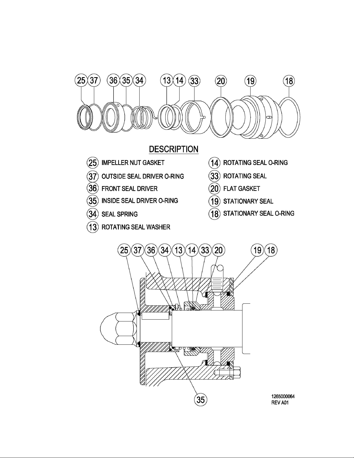
ShAFT SEALS
FP Mechanical Seal Type .......................................................................................Single or Double Internal
Seal Flush Water Pressure (double seal only) .............................................................................. 5 Max. PSI
Seal Water Consumption (double seal only) ..................................................................................... 1-2 gph
FPX Mechanical Seal Type ......................................................................................................Single Internal
Stationary Seal Ring Material ...........................................................................................Carbon (standard)
Also available in ........................................................................................... Silicon Carbide
Rotating Seal Ring Material ................................................................Chrome Oxide coated Stainless Steel
Also available in ........................................................................................... Silicon Carbide
Double Rotating Seal Material (FP only) .......................................................................................... Ceramic
O-ring Material ..................................................................................................................... Viton (standard)
Also available in .................................................................... others available upon request
RECOMMENDED TORqUE VALUES
Impeller nut Models 700–3550 40 ft.-lbs.
Models 1050, 1150 and 1160 90 ft.-lbs.
Shaft collar screw 56C–180TC motor frames 12 ft.-lbs.
210TC–280TSC motor frames 24 ft.-lbs.
280TC–320TD/TSD, 360TSC motor frames 43 ft.-lbs.
Motor bolts 56C - 140TC motor frames 20 ft.-lbs.
180TC–280TSC motor frames 55 ft.-lbs.
280TC–320TD/TSD, 360TSC motor frames 110 ft.-lbs.
Seal retaining ring bolts All models (except FPX 250TC) 10 ft.-lbs.
FPX 250TC 4.5 ft. lbs.
Housing bolts (double flange) All models 50 ft.-lbs.
Clamping bolt (single flange) All models 55 ft. lbs.
MOTOR INFORMATION
Uses standard NEMA TEFC C-face motors (except D-flange motors for 320TSD). Options include washdown, high efficiency, explosion proof, chemical duty and IEC.
VOLTAGE AND FREqUENCY
3 phase, 60 Hz, 208-230/460 VAC .........................................................................................1750/3500 RPM
3 phase, 60 Hz, 575 VAC ........................................................................................................1750/3500 RPM
3 phase, 50 Hz, 208-220/380-415 VAC ..................................................................................1450/2900 RPM
ShAFT RUN-OUT TOLERANCE

Fristam FP/FPX Series Pump
All models ...........................................................................................................................0.05 mm (0.002”)
IMPELLER GAPS TO hOUSING TO COVER
700, 710, 720, 740, 1740....................................................... 0.5 mm (0.020”) ....... 0.5 mm (0.020”)
352......................................................................................... 0.5 mm (0.020”) ........ 1 mm (0.040”)
353, 1050............................................................................... 1 mm (0.040”) ........... 0.5 mm (0.020”)
354......................................................................................... 1 mm (0.040”) ........... 1 mm (0.040”)
345, 355................................................................................. 1.5 mm (0.060”) ........ 0.5 mm (0.020”)
1150, 1160............................................................................. 1.5 mm (0.060”) ........ 2.0 mm (0.080”)
RECOMMENDED PREVENTIVE MAINTENANCE
RECOMMENDED SEAL MAINTENANCE
Visually inspect mechanical seal daily for leakage.
Replace mechanical seal annually under normal duty.
Replace mechanical seal as often as required under heavy duty.
ELASTOMER INSPECTION
Inspect all elastomers when performing pump maintenance. We recommend replacing elastomers (orings and gaskets) during seal, pump shaft and/or motor replacement. If the impeller nut gasket fails,
the threaded hole on the impeller nut and the threads on the end of the shaft will need to be cleaned. A
wire brush is recommended for cleaning these threads.
5
MOTOR LUbRICATION RECOMMENDATIONS
Use a high grade ball and roller bearing grease. Recommendations for standard service conditions
include Shell Dolium R or Chevron SRI. (See Tables 1-3 for more details.)
Table 1: Motor Lubrication Intervals for Standard Conditions*
Frame Size: NEMA (IEC) 3500 RPM 1750 RPM
Up to 210 incl. (132 IEC) 5,500 hrs. 12,000 hrs.
Over 210 to 280 incl. (180 IEC) 3,600 hrs. 9,500 hrs.
Over 280 to 360 incl. (225 IEC) 2,200 hrs. 7,400 hrs.
*For severe conditions, multiply interval hours by 0.5; for extreme conditions, multiply interval hours by 0.1
Table 2: Service Conditions Definitions
Service
Conditions
Standard 104°F (40°C) Clean, little corrosion
Severe 122°F (50°C) Moderate dirt, corrosion
Extreme >122°F (50°C) Severe dirt, abrasive dust, corrosion
Table 3: Volume of Grease to be Added per Bearing
Frame Size
NEMA (IEC)
Up to 210 incl. (132 IEC) 0.6 2.0
Over 210 to 280 incl. (180 IEC) 1.2 3.9
Over 280 to 360 incl. (225 IEC) 1.5 5.2
Max. Ambient
Temperature
Atmospheric Contamination
Grease
3
IN
Volume
TSP
Fristam FP/FPX Series Pump
6
SEAL REPLACEMENT
Begin all pump maintenance by disconnecting the energy source to the pump. Observe
!
TOOLS FOR SEAL REPLACEMENT
15/16” socket
Two 3/4” wrenches
7/16” wrench
3/32” Allen wrench
3/8” diameter steel rod
Pliers (channel locks)
Screwdriver (flat blade)
Soft-faced hammer (5-lb. dead-blow)
Food grade lubricant
Optional tool: One pair of impeller pullers (can be purchased through Fristam)
PUMP hEAD DISASSEMbLY
Note: the reference numbers listed in the text (#) refer to the assembly drawing on pages 18-21.
! WARNING
a) Loosen the cover nuts (26) with the soft-faced hammer and remove.
b) Remove the pump cover (24) and the cover gasket (21).
c) Remove the seal water pipes (on pumps with a double me-
chanical seal or water casade option) by turning them
counter-clockwise with the pliers.
d) Loosen and remove the guard screw (3). Next remove
the shaft guard (35).
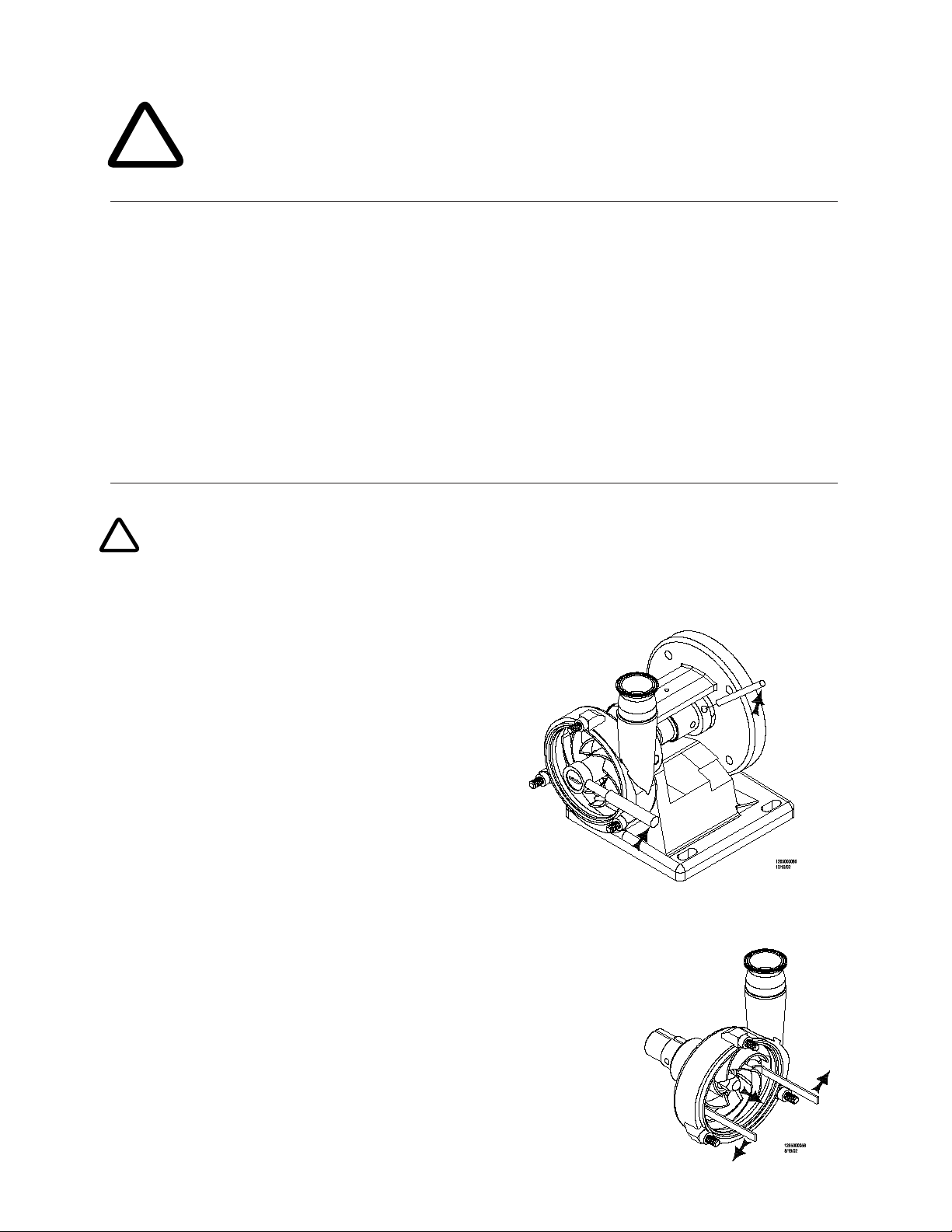
e) Place the 3/8” diameter rod in the pump shaft hole.
Allow the rod to rest against the pump flange support
(2) to prevent the shaft from rotating while loosening
the impeller nut (23) with the 15/16” socket wrench
(Figure 7). Remove the impeller nut and the impeller
nut gasket (25).
f) Remove the impeller (22) from the pump shaft (7) by
grasping an impeller blade in each hand and pulling the
impeller toward you. If the impeller is difficult to pull off the
shaft, wedge the impeller pullers between the pump housing (10) and the back of the impeller and
pry off the impeller (Figure 8).
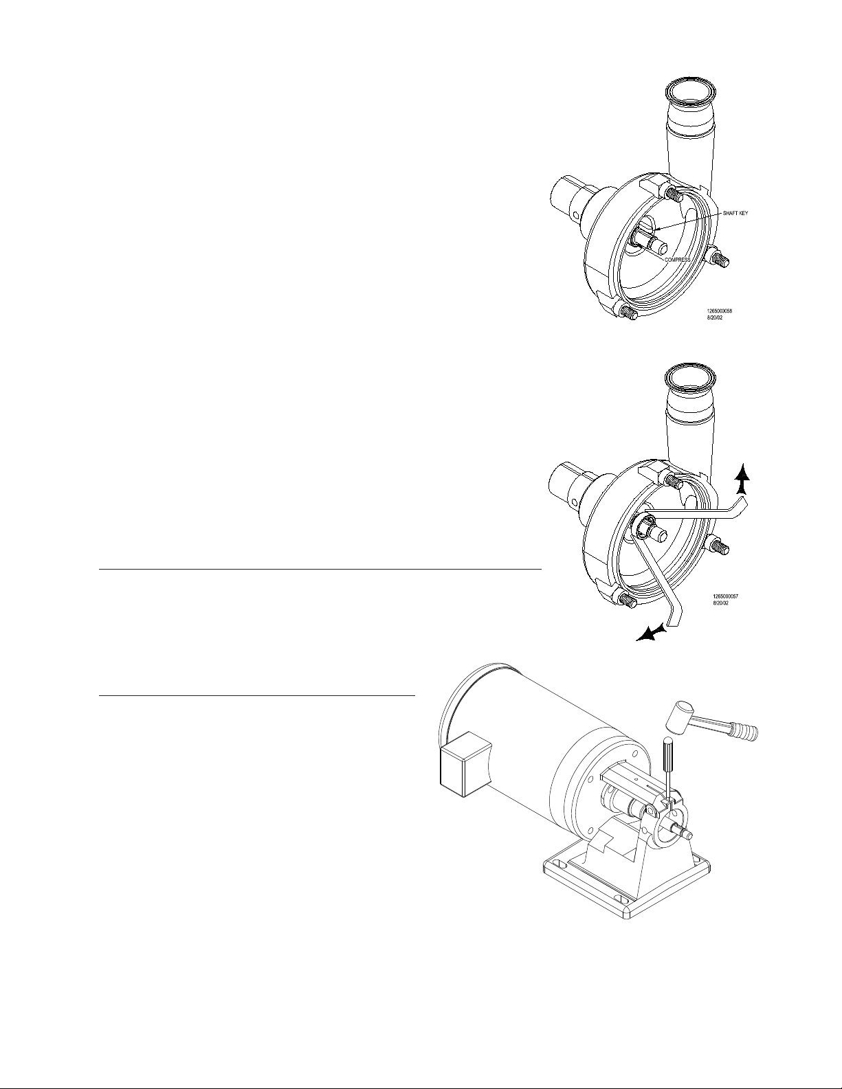
g) Compress the seal spring (34) by pushing on the front seal driver (36) and lift
out the impeller key (8) (Figure 9). (You may find it easier to rotate the
keyway to bottom of the shaft, compress the seal spring, and let the key
drop out.)
h) Next remove the front seal driver and seal spring by pulling them off
the pump shaft and discard them.
i) Remove the rotating seal, seal washer and o-ring by gently placing the
flat ends of two impeller pullers on either side of the rotating seal and
carefully pull (wiggling the seal ring side-to-side should aid removal)
all lock out/tag out procedures as outlines by ANSI Z244.1-1982 and OSHA 1910.147 to
prevent accidental start-up and injury.
Disconnect the suction and discharge piping from the pump. Drain all fluid from
the pump prior to disassembly.
Figure 7
Figure 8
until the rotating seal face comes off the shaft (Figure 10). Discard
8/21/02
the seal components after you remove them.
j) SINGLE FLANGE: Loosen the housing clamping bolt with the two
3/4” wrenches until it is loose in the flange support. (Note: the
clamping bolt does not have to be removed.) Now slide the pump
housing off the end of the pump shaft. If the pump housing does
not come out of the flange support easily, widen the flange support
by driving a screwdriver into the slot on top (Figure 11).
DOUBLE FLANGE: Loosen and remove the four housing bolts that
pass through the flange support and thread into the back of the
pump housing with the 3/4” wrench. Slide the pump housing off
the end of the pump shaft.
k) Place the pump housing face down on the housing studs.
l) Loosen the retaining ring bolts with the 7/16” wrench and remove
them from the hub of the pump housing.
m) Remove the retaining ring.
n) Place a finger through the stationary seal, pull it out of the seal
cavity and discard. If the stationary seal has been in the pump for
an extended period, it may be necessary to softly tap it out from the
opposite end using a rubber mallet.
If you have a Silicon Carbide Stationary sPLIT Seal design - two
pieces will be removed.
o) Check for the flat gasket in the bottom of the seal cavity. Remove
this gasket, discard and clean the seal cavity if necessary.
Fristam FP/FPX Series Pump
7
Figure 9
Figure 10
ADDITIONAL DISASSEMbLY FOR DOUbLE MEChANICAL SEALS (FP SERIES ONLY)
To remove the rear seal components (only pumps with double seal),
carefully slide the rear rotating seal, seal washer, the seal o-ring off the
pump shaft and discard. Use the 3/32” Allen wrench to remove the rear
seal driver and spring off the pump shaft and discard.
PUMP hEAD ASSEMbLY
(SEE SEAL ASSEMbLY DRAWINGS PAGES 10-13)
NOTE: when installing the new seal components
make sure that you use all of the components supplied with the replacement seal kit. Using some of
the old components may reduce seal life.
For double mechanical seals only (FP Series
only), first install the rear seal components. Note:
this includes the seal washer, the seal o-ring, the
rear rotating seal and the rear seal driver and
spring.
You are now ready to install the stationary seal
into the pump.
a) To install the stationary seal into the hub of the
pump housing, place the pump housing on a clean surface with the hub side up. Inspect the hub
area to ensure that it is clean.
b) Place the flat gasket into the hub of the pump housing. Make sure that it is all the way to the bottom
and is seated evenly.
Figure 11
1265000063

Fristam FP/FPX Series Pump
1265000060
8/21/02
RETAINING RING BOLT
8
c) Install the stationary seal into the housing hub with the smaller face entering the hub first.
For the Silicon Carbide Stationary Seal design (Figures 18 and 21) - install the front half of the
stationary seal into the housing hub with the smaller face side first. Then install the rear half of the
stationary seal.
d) Install the stationary seal o-ring (do not lubricate this o-ring) onto the back of the stationary seal.
Improper fit may cause leakage or seal damage.
e) Place the retaining ring on the housing hub, aligning the holes in the retaining ring with the holes
in the hub.
f) Thread the four retaining ring bolts through the holes in the stationary seal retaining ring and into
the housing hub. Alternately tighten the bolts so the retaining ring secures evenly. Uneven tightening could result in seal damage. Check for proper torque on page
5.
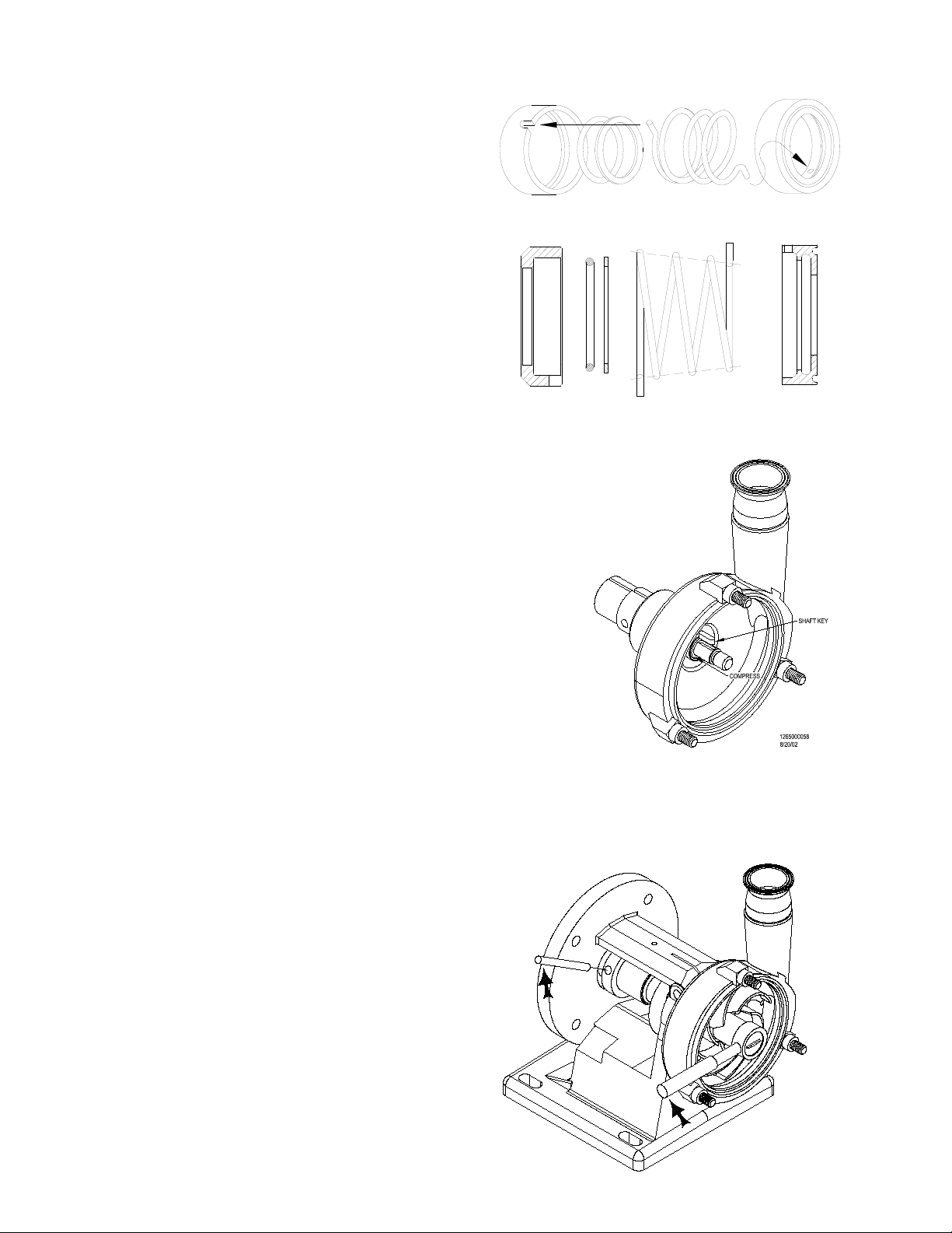
g) SINGLE FLANGE: Carefully slide the pump housing over
Figure 12
the pump shaft and back against the flange support. The
stationary seal may be damaged if it makes hard contact with the pump shaft. If the pump housing does
not slide into the flange support easily, widen the
flange support by driving a screwdriver into the slot
on top (Figure 13). Slide the pump housing all the
way into the flange support until the shoulder of
the housing is against the flange support. Remove
the screwdriver. If the pump has a double mechanical seal or water cascade option, make sure that the
water pipe holes in the pump housing are aligned with
the holes in the flange support. While holding the pump
housing against the flange support, tighten the clamping bolt
in the flange support.
DOUBLE FLANGE: Carefully slide the pump housing (10) over the pump shaft (7) and back against
the flange support (2). Note: the stationary seal may be damaged if it makes hard contact with the
pump shaft. Install the housing bolts (29) and washers (30). Tighten to the proper torque listed on
page 4. Install the seal water pipe (if supplied), by threading it into the housing and tighten with a
pair of pliers. Align the discharge piping with the discharge outlet.
h) Install the seal water pipes (for double mechanical seals
Figure 13
or water cascade option), by threading them into the
housing and tighten with the pliers.
i) You are now ready to install the rotating seal assembly.
First lubricate the seal o-ring with a food grade lubricant (unless the o-ring material is EPDM, then only water should be used for lubrication). Place the seal o-ring
inside the rotating seal.
j) Now place the seal washer into the rotating seal.
k) Next install the one end of the seal spring into the rotat-
ing seal making sure that the tab of the spring is in the
slot on the rotating seal. (Note: for frame sizes 254 and
up, the larger end of the seal spring goes into the rotating seal Figure 14)
l) Finally, install the tab on the other end of the seal spring into the hole on the front seal driver
(Figure 14). The rotating seal assembly is now ready to be installed onto the pump shaft. (Note: for
pumps with a 735 seal, the larger end of the seal spring goes into the rotating seal.)
1265000063
8/21/02
Fristam FP/FPX Series Pump
1265000087
12/10/02
m) Rotate the pump shaft so the keyway is on top.
Now slide the rotating seal assembly which includes: the rotating seal, the seal o-ring, the seal
washer, the seal spring and the seal driver onto the
pump shaft.
n) Lubricate the outside o-ring with a food grade
lubricant, if it is not EPDM, and install it in the
Figure 14
groove on the front of the seal spring and driver
assembly.
o) Compress the spring assembly with two fingers
and install the impeller key into the keyway on the
pump shaft (Figure 15).
p) Slide the impeller onto the pump shaft. The slot in
the impeller hub will slide over the impeller key.
q) Generously lubricate the new impeller nut gasket
with a food grade lubricant (if it is not EPDM) and place it onto the impeller nut.
r) Thread the impeller nut with the gasket in place onto the pump shaft.
s) Place the 5/16” diameter rod in the pump shaft hole. Allow the
rod to rest against the pump flange support to keep the shaft
Figure 15
from rotating while tightening the impeller nut with the 15/16”
socket wrench (Figure 16). Tighten to the proper torque listed
on page 5.
t) Now install the new cover gasket onto the pump cover. When
placing the cover gasket into the pump cover, gently stretch the
gasket into position. Do not roll the gasket into position. With
the cover gasket in position, place the pump cover onto the
front of the pump. (Note: the pump serial number is stampeded
into the ‘top’ of the pump cover.)
u) Thread the cover nuts onto the housing studs. Make sure the
cover o-ring is properly seated in the cover to ensure that it will
not get pinched when tightening the cover nuts. Tighten the
cover nuts by tapping on them with the soft-faced hammer.
v) Now rotate the pump shaft to make sure that the impeller moves freely. If it does not, recheck your
assembly to make sure that gaskets are not pinched and everything is seated properly.
Listen to the pump as you turn the shaft. A small amount of noise from the seals is normal, but if there
is metal-to-metal contact, the sound will be notice-
Figure 16
able. If there is metal-to-metal contact, check the
impeller gap. Regap the impeller if necessary. See
page 16 for directions. Replace the shaft guard and
secure with the guard screws.
Reconnect the suction and discharge piping.
WARNING: Mechanical seals must never run dry, even
momentarily. Seal damage will result.
9
Fristam FP/FPX Series Pump
10
SINGLE SEAL ASSEMbLY
 Loading...