

Fristam Pumps FPM 711, FPM 712, FPM 721, FPM 722, FPM 741 English Translation Of The Original German Operating Manual
...
English translation of the original
German Operating Manual
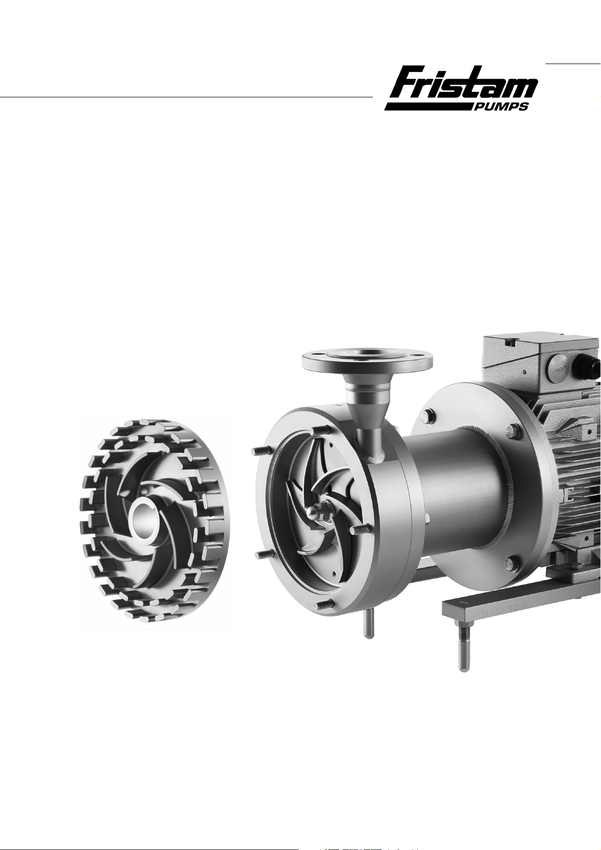
Centrifugal pump
FPM Series,
Rotary Homogenizers
FSM Series
Pump type:
Pump no.:

Copyright
© Copyright 2016 Fristam Pumpen KG (GmbH & Co.)
All rights reserved. The contents of this operating manual, including images and
design, are subject to the protection of copyrights and other trade-related intellectual
property rights. It is not permitted to disseminate or alter the content of this manual.
Nor may the said content be copied, disseminated, altered or made available to third
parties for commercial purposes.
The original version of this document is the German version.
All other languages are translations of the original version.

1 Introduction............................................... 3
7 Operation................................................... 10
1.1 Foreword.................................................................. 3
1.2 Manufacturer.......................................................... 3
1.3 Scope of Supply..................................................... 3
1.4 Scope of documentation ................................... 3
1.5 Display Conventions............................................ 3
2 Safety.......................................................... 4
2.1 Basic safety instruction ....................................... 4
2.2 Intended Use .......................................................... 4
2.3 Improper Use.......................................................... 4
2.4 Labels ........................................................................ 4
2.5 Noise emission....................................................... 5
2.6 Disposal .................................................................... 5
3 Design and Function ................................. 5
3.1 Principles of Design.............................................. 5
3.2 Model ........................................................................ 6
3.3 Type designation .................................................. 7
3.4 Versions .................................................................... 7
3.5 Pump Sizes .............................................................. 7
4 Transportation........................................... 7
4.1 Safety instructions ................................................ 7
4.2 Moving With Industrial Trucks ......................... 7
4.3 Moving With Crane............................................... 7
5 Storage ....................................................... 8
7.1 Safety instructions................................................. 10
7.2 Commencement of Operation ......................... 10
7.3 Monitoring of Operation .................................... 11
7.4 Stopping of Operation ........................................ 11
7.5 Decommission pump........................................... 11
7.6 Cleaning during operation ................................ 12
8 Faults.......................................................... 12
8.1 Safety instructions................................................. 12
9 Maintenance.............................................. 12
9.1 Safety instructions................................................. 12
9.2 Replacement Parts................................................ 13
9.3 Lubricating the motor bearing......................... 13
9.4 Changing the motor............................................. 13
9.5 Replacing the magnetic coupling................... 13
9.6 Pump Head Removal............................................ 13
9.7 Checking of the Clearances ............................... 14
9.8 Mounting the pump head.................................. 16
10 Appendix 1 ................................................ 18
10.1 Specifications.......................................................... 18
10.2 Maintenance intervals ......................................... 18
10.3 Troubleshooting table......................................... 19
10.4 Number Key............................................................. 21
10.5 EC Declaration of Conformity ........................... 22
5.1 Safety......................................................................... 8
5.2 Storage conditions ............................................... 8
5.3 Long-Term Storage .............................................. 8
5.4 Recommissioning ................................................. 8
6 Installation ................................................. 9
6.1 Safety instructions ................................................ 9
6.2 Installation site....................................................... 9
6.3 Prevention of noise and vibration .................. 9
6.4 Pump Fixation ........................................................ 9
6.5 Electrical connection ........................................... 10
6.6 Cleaning ................................................................... 10
1

/ / FPM AND FSM SERIES / / /
2
1 Introduction
1.1 Foreword
This operation manual describes all sizes, models and versions
of the FPM and FSM series.
Information on the model, size, and version of your pump can
be found on the rating plate on your pump and in the "Order-Re-
lated Documents" in the attached documents.
1.2 Manufacturer
Fristam Fristam Pumpen KG (GmbH & Co.)
Kurt-A.-Körber-Chaussee 55
21033 Hamburg
GERMANY
Tel.: +49 (0) 40 / 7 25 56 -0
Fax: +49 (0) 40 / 7 25 56 -166
email: info@Fristam.de
1.3 Scope of Supply
The package includes the following items:
– Covers for pipe fittings
– Optional: Fristam accessories
– Optional: assembly kit
– Documentation
Check the shipment for completeness and damage. Immedi-
ately notify Fristam of any missing items or damage.
1.5 Display Conventions
List items are preceded by dashes:
– Part 1,
– Part 2.
Handling instructions that must be performed in a specified order are numbered:
1. Turn device on.
2. Turn device off.
Handling instructions that do not need to be performed in
a specified order are preceded by triangular bullets:
Action.
Action.
1.5.1 Safety instructions
DANGER
A safety instruction with the signal word "Danger" indicates personal hazards causing death or serious injury.
WARNING
A safety instruction with the signal word "Warning" indicates
personal hazards that may lead to death or serious injury.
CAUTION
A safety instruction with the signal word "Caution" indicates personal hazards that may lead to mild to moderate injuries.
NOTE
A safety instruction with the signal word "Note" warns of the
possibility of material damage.
1.4 Scope of documentation
The documentation includes the following items:
– this operating manual,
– Maintenance, lubrication, and tightening torque tables
can be found in the appendix 1.
– Attached documents
– Order-related documents,
– Data sheet of magnetic coupling,
– Supplier Documentation (motor, etc.),
– Declaration of Conformity,
– documentation about Fristam accessories, if applicable,
– certificates (materials certificates, etc.), if applicable.
3
/ / FPM AND FSM SERIES / / /
2 Safety
2.1 Basic safety instruction
Please read this operator's manual completely before using
the pump and keep it available at the pump installation location.
Heed the applicable national regulations of the owner's
country and the company's work and safety regulations.
All work described here may only be performed by qualified
experts with caution.
Danger of contamination: Heed legal and operational safety
regulations when pumping dangerous media.
2.2 Intended Use
The centrifugal pumps FPM are used to convey liquids with a dynamic viscosity of at least 0.35 mPas, up to a maximum of
1,200 mPas and media temperatures of max. 150°C / 250°C (depending on the material). The medium may contain small
amounts of air or gases, it may be homogeneous and may contain minute admixtures; however, solids exceeding a size of >
0.1 mm are not permitted.
The FSM series is designed for the homogenization of fluids or
mixtures. The temperature of the pumping medium can rise to
a maximum 150°C / 250°C. The medium may contain small
amounts of air or gases, it may be homogeneous and may contain minute admixtures; however, solids exceeding a size of
> 0.1 mm are not permitted.
Each pump is designed according to customer requirements.
The seal materials have been selected for the respective medium. The pump may only be used to pump the medium it was
designed for (see "Order-Related Documents" in the attached
documents).
2.4 Labels
Do not alter or remove the labels on the pump.
Immediately replace damaged or lost labels with ones that
are true to the originals.
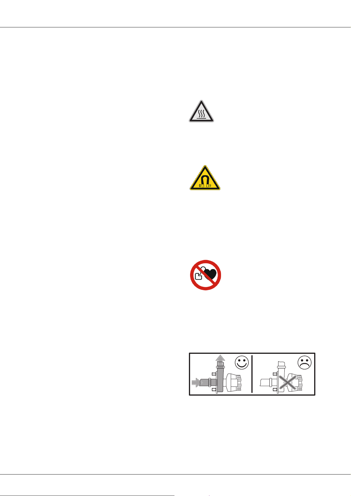
2.4.1 Warning signs
Fig. 1 Safety label: “Hot surface”
This label indicates that parts can become hot during operation
or, if applicable, that hot media is being pumped. Only touch
the pump if you are wearing suitable gloves.
Fig. 2 Safety label: "Magnetic field"
This sign indicates that a strong magnetic field is present in
some parts of the magnetic coupling. If you carry a magnetic
data medium, you must remain outside a radius of 1 m to the
magnetic coupling. When using magnetic parts/tools within
a radius of 0.5 m, extreme caution is recommended. Due to the
magnetic pull there is an inherent risk of injury and damage to
the parts.
Fig. 3 Safety label: "Persons with pacemakers are not permitted beyond this point"
2.3 Improper Use
The standard version of the FPM and FSM series must not be
used in an explosive atmosphere. Special explosion-proof versions are available for this.
Pumping of media other than those specified can destroy the
pump.
Pumping of foreign objects with the media can destroy the
pump.
Standard pump units from Fristam are described in this operator's manual. If nonstandard items or extras are installed, the operator assumes the responsibility for operation.
Modifications and changes to the pump are only permitted after
consultation with Fristam.
4
This sign indicates that persons with heart pacemakers implanted defibrillators are not permitted near the pump. Persons using
a heart pacemaker must remain at a distance of at least 2 m to
the pump.
2.4.2 No dry running
Fig. 4 Safety label: “No dry running”
This label indicates that the pump cannot be run dry. There
must always be medium in the suction line and the pump when
the pump is started. Otherwise the pump will be damaged.
2.4.3 Direction of rotation
2.6 Disposal
Fig. 5 Label: "Impeller Direction of Rotation"
This label shows the direction of rotation of the impeller. It is located at the front on the pump cover.
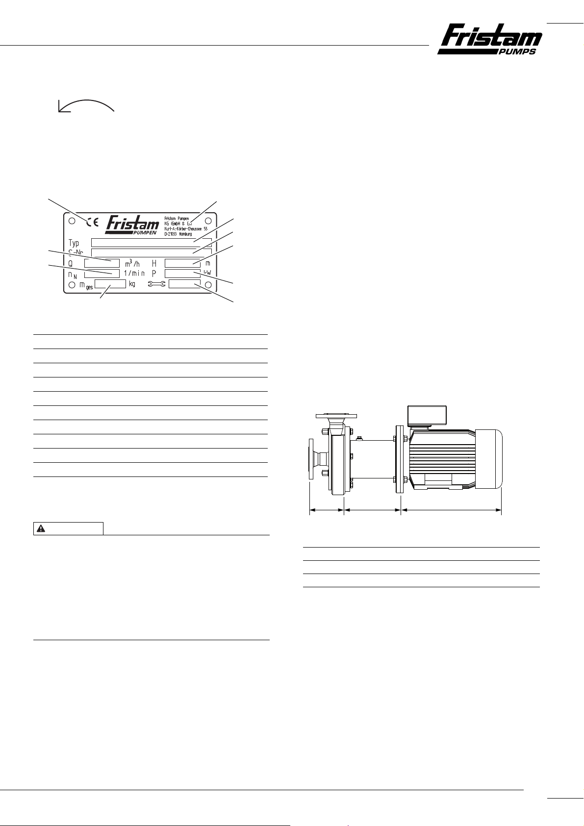
2.4.4 Rating plate
10
1
2
3
9
4
8
5
7
Fig. 6 Type plate for the pump unit
Manufacturer
1
Type: Pump series, size, model, version
2
S. no.: Serial number of the pump
3
H: discharge head [m]
4
Motor output [kW]
P:
5
Year of manufacture
6
: Mass (total) [kg]
m
7
tot
: Rated speed [rpm]
n
8
N
Q: Flow rate [m³/h]
9
CE mark
10
6
2.6.1 Disposal of Transportation Package
Recycle the transportation package.
2.6.2 Disposal of pump
1. Carefully clean the pump. Dispose of residues in an environmentally friendly manner in accordance with applicable regulations.
2. Dismantle the pump into its constituent parts.
3. Dispose of the pump parts in an environmentally friendly
manner in accordance with applicable regulations.
2.6.3 Disposal of electrical and electronic scrap
Dispose of electrical and electronic scrap in accordance with
applicable directives.
3 Design and Function
3.1 Principles of Design
2.5 Noise emission
CAUTION
Noise Generated by Running Pump
Hearing damage.
Wear ear protectors when using pumps specified for sound
pressure levels of greater than 80 dBA.
The local noise exposure regulations must be complied with.
For noise emission values for the pumps, please see
Chapter 10.1 "Specifications", Page 18.
AB C
Fig. 7 Basic layout of the pumps; here the FPM model is shown as an example
A Pump head
B Lantern
C Electric motor
5
/ / FPM AND FSM SERIES / / /
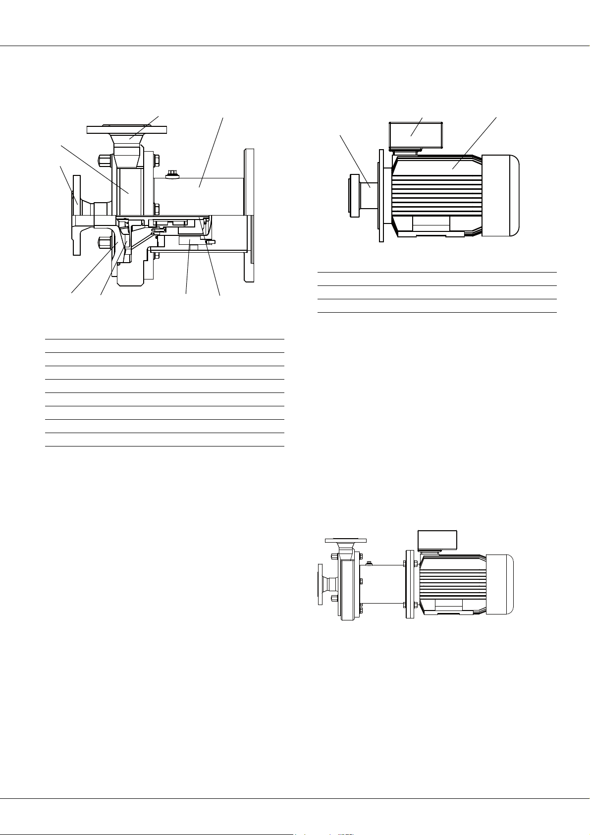
3.1.1 Pump head (A) and lantern (B)
11
17
16
15
14
Fig. 8 Pump head and lantern
11 Discharge line connection
12 Magnetic coupling
13 Impeller
14 Pump cover
15 Suction line connection
16 Pump casing
17 Lantern
18 Pump shaft
13
12
18
Magnetic coupling (12)
The magnetic coupling ensures the touchless power transfer of
the drive line.
3.1.2 Electric motor (C)
19
20
21
Fig. 9 Electric motor
19 Electric power connection
20 Electric motor
21 Flange shaft
Lantern (17)
The lantern connects the pump casing with the motor.
– The pump casing is screwed to the lantern via a flange con-
nection.
Electric motor (19)
The following motor type can be mounted:
IEC standard motor with A-sided fixed bearing (drive side) with
fitted key and shaft pin in models:
– IM B3/B5: Motor model with flange and base.
3.2 Model
Impeller (13)
– The FPM pump series uses open impellers.
– The impellers of the FSM pump series uses gears. The gears
mesh with the gears of the pump cover.
The FSM pumps use drive gears exclusively with impellers.
Pump cover (14)
The connection for the suction line is located on the pump cover.
Pump casing (16)
The connection for the discharge line is located on the pump
casing.
Model FPM…V or FSM…V
Fig. 10 Model FPM…V or FSM…V
Motor: IEC standard motor, model B3/B5
Layout: with lantern
6
 Loading...