

Fristam Pump FZP 10, FZ Series, FZ 22, FZ 25, FZ 27 Original Instructions, Assembly Instructions
...
Original Instructions
Assembly Instructions
Side Channel Pump
FZ Series
Pump Type:
Pump No.:

Copyright
© Copyright 2012 Fristam Pumpen KG (GmbH & Co.)
All rights reserved. The contents, including graphic images and layout of this operating instructions
manual are subject to copyright protection and to other laws for the protection of intellectual property.
The publication and modification of the contents are not authorised. Moreover, you may not copy,
publish and alter the contents therein for commercial purposes, or transmit the information to a third
party.
The German version is the original version of the operating instructions manual.
Other languages are translations of the original operating manual.

Table of cont e n t s
1 Introduction............................................................. 5
1.1 Foreword................................................................... 5
1.2 Manufacturer........................................................... 5
1.3 Scope of Supply...................................................... 5
1.4 Pump Without Motor (Optional)...................... 5
1.5 Scope of Documentation.................................... 5
1.6 Display Conventions............................................. 5
2 Safety Instructions................................................. 6
2.1 Basic Safety Instructions...................................... 6
2.2 Intended Use ........................................................... 6
2.3 Improper Use........................................................... 6
2.4 Warning and Instruction Labels........................ 6
2.5 Noise Emissions ...................................................... 7
2.6 Disposal ..................................................................... 7
3 Design and Function ............................................ 7
3.1 Principles of Design............................................... 7
3.2 Models ....................................................................... 8
3.3 Pump Key.................................................................. 9
3.4 Versions ..................................................................... 9
3.5 Pump Sizes ............................................................... 9
4 Transportation ........................................................ 10
4.1 Safety Instructions................................................. 10
4.2 Moving With Industrial Trucks .......................... 10
4.3 Moving With Crane ............................................... 10
5 Storage....................................................................... 11
5.1 Safety Instructions................................................. 11
5.2 Storage Conditions................................................ 11
5.3 Long-Term Storage ............................................... 11
5.4 Recommissioning .................................................. 11
6 Installation................................................................ 11
6.1 Safety Instructions................................................. 11
6.2 Installation Location ............................................. 11
6.3 Reduction of Noise and Vibration.................... 12
6.4 Pump Fixation ........................................................ 12
6.5 Electrical Connection........................................... 13
6.6 Connection of Sealing or Quenching
Liquid (Optional) ................................................... 13
6.7 Cleaning.................................................................... 13
7 Operation................................................................. 14
7.1 Safety Instructions ................................................ 14
7.2 Commencement of Operation......................... 14
7.3 Monitoring of Operation .................................... 14
7.4 Stopping of Operation ........................................ 14
7.5 Pump Decommissioning.................................... 14
7.6 Cleaning in Place................................................... 15
8 Faults ......................................................................... 15
8.1 Safety Instructions ................................................ 15
9 Maintenance........................................................... 15
9.1 Safety Instructions ................................................ 15
9.2 Replacement Parts................................................ 15
9.3 Inspection of Sealing and Quenching
Liquid (Optional) ................................................... 16
9.4 Lubrication of Motor Bearings.......................... 16
9.5 Lubrication of Shaft Bearing ............................. 16
9.6 Motor Replacement ............................................. 17
9.7 Shaft Seal Replacement ...................................... 18
9.8 Pump Head Removal ........................................... 18
9.9 Checking of the Clearances............................... 20
9.10 Pump Head Attachment..................................... 20
9.11 Design FZ 27: Mounting and aligning the
pump shaft .............................................................. 29
9.12 Model L: Coupling Replacement ..................... 30
10 Appendix 1 .............................................................. 31
10.1 Specifications.......................................................... 31
10.2 Maintenance Intervals......................................... 31
10.3 Troubleshooting Table........................................ 32
10.4 Number Key ............................................................ 34
10.5 EC Declaration of Conformity........................... 35
10.6 EG Declaration of Incorporation...................... 35
3

/ / FZ pump series / / /
11 Appendix 2 – Assembly Instructions
(Optional).................................................................. 36
11.1 Safety Instructions................................................. 36
11.2 Scope.......................................................................... 36
11.3 Moving Without Motor........................................ 36
11.4 Installation Location ............................................. 37
11.5 Pump Installation................................................... 37
4
1Introduction
1.1 Foreword
This operator's manual describes all sizes, models, and versions
of the FZ pump series.
Information on the model, size, and version of your pump can
be found on the rating plate on your pump and in the "Order-Re-
lated Documents" in Appendix 2.
– Attached documents
– Order-Related Documents
– Supplier Documentation (motor, coupling, etc.)
– Documentation on Fristam accessories (if applicable)
– Certificates (materials certificates, etc.), if applicable
– Declaration of Conformity
1.6 Display Conventions
1.2 Manufacturer
FRISTAM Pumpen KG (GmbH & Co.)
Kurt-A.-Körber-Chaussee 55
21033 Hamburg
GERMANY
Tel.: +49-40 - 72556 -0
Fax: +49-40 -72556 -166
E-mail: info@fristam.de
1.3 Scope of Supply
The package includes the following items:
– Pump with motor = pump unit
optional: without motor
– Covers for pipe fittings
– Optional: assembly kit
– Fristam accessories (if applicable)
– Documentation
► Check the shipment for completeness and damage. Immedi-
ately notify Fristam of any missing items or damage.
List items are preceded by dashes:
–Part 1
–Part 2
Handling instructions that must be performed in a specified order are numbered:
1. Turn device on.
2. Turn device off.
Handling instructions that do not need to be performed in a
specified order are preceded by triangular bullets:
► Action
► Action
1.6.1 Safety Instructions
A safety instruction with the signal word "Danger" indicates personal hazards causing death or serious injury.
A safety instruction with the signal word "Warning" indicates
personal hazards that may lead to death or serious injury.
1.4 Pump Without Motor (Optional)
The pump can optionally be supplied without a motor. In this
case, continue reading up to and including Chapter 3, "Design
and Function," page 7, and then skip to Chapter 11, "Appendix 2 –
Assembly Instructions (Optional)," page 36.
1.5 Scope of Documentation
The documentation includes the following items:
– This operator's manual
– Maintenance, lubrication, and tightening torque tables
can be found in Appendix 1.
– The assembly instructions for the option "Pump Without
Motor" can be found in Appendix 2.
A safety instruction with the signal word "Caution" indicates personal hazards that may lead to mild to moderate injuries.
A safety instruction with the signal word "Note" warns of the
possibility of material damage.
5
/ / FZ PUMP SERIES / / /
1
2
3
5
4
6
7
8
9
10
2 Safety Instructions
2.1 Basic Safety Instructions
► Please read this operator's manual completely before using
the pump and keep it available at the pump installation location.
► Heed the applicable national regulations of the owner's
country and the company's work and safety regulations.
► All work described here may only be performed by qualified
experts with caution.
► Danger of contamination: Heed legal and operational safety
regulations when pumping dangerous media.
2.2 Intended Use
The standard versions of the FZ pump series are designed for
use in the food industry, the pharmaceutical and biotechnology
industry, and CIP process technology.
FZ pump series pumps are used for the following applications:
– Pumping of products containing gas
– Venting of suction lines
– Emptying of residues in product lines
The FZ pump series can generate discharge pressures of up to
7.0 bar. Depending on the pump size, the system pressure can
reach 15 bar.
Each pump is designed according to customer requirements.
The seal materials have been selected for the respective pumping conditions (medium, pressure, temperature). The pump may
only be used to pump the medium it was designed for
(see Order-Related Documents in the attached documents in
Appendix 2).
2.4.1 Hot Surface
Fig. 1 Safety label: "Hot Surface"
This label indicates that parts can become hot during operation
or, if applicable, that hot media is being pumped. Only touch
the pump if you are wearing suitable gloves.
2.4.2 No Dry Running
Fig. 2 Safety label: "No Dry Running"
This label indicates that the pump cannot be run dry. There
must always be medium in the suction line and the pump when
the pump is started. Otherwise, the pump will be damaged.
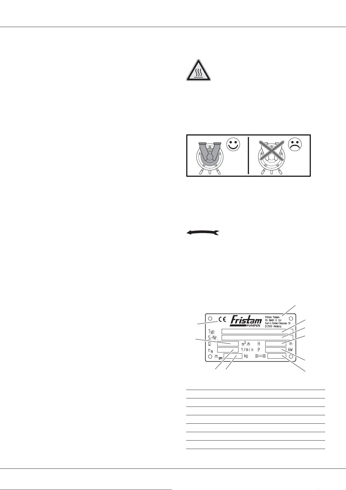
2.4.3 Direction of Rotation
Fig. 3 "Impeller Direction of Rotation" label
This label shows the direction of rotation of the impeller. It is located at the front on the pump cover.
Fristam can provide operation independent of the direction of
rotation for special versions.
2.4.4 Rating Plate
2.3 Improper Use
The standard FZ pump series versions may not be used in explosive atmospheres. Special explosion-proof versions are available
for this.
Pumping of media other than those specified can destroy the
pump.
Standard pump units from Fristam are described in this operator's manual. If nonstandard items or extras are installed, the operator assumes the responsibility for operation.
Modifications and changes to the pump are only permissible
with the explicit consent of Fristam.
2.4 Warning and Instruction Labels
► Do not alter or remove the labels on the pump.
► Immediately replace damaged or lost labels with ones that
are true to the originals.
6
Fig. 4 Pump unit rating plate
Manufacturer
1
Typ: pump series, pump size, model, version
2
S.-Nr.: serial number of the pump
3
H: discharge head [m]
4
motor output [kW]
P:
5
Year of manufacture
6
ttl: mass (total) [kg]
m
7
n
B
C
A
11
12
13
14
15
: rated speed [1/min]
8
R
Q: flow rate [m³/h]
9
CE mark
10
2.5 Noise Emissions
► The local noise exposure regulations must be complied with.
For noise emission values for the pumps, please see
Chapter 10.1, "Specifications," page 31.
Noise Generated by Running Pump
Hearing damage.
► Wear ear protectors when using pumps with specified sound
pressure levels of greater than 80 dBA.
2.6 Disposal
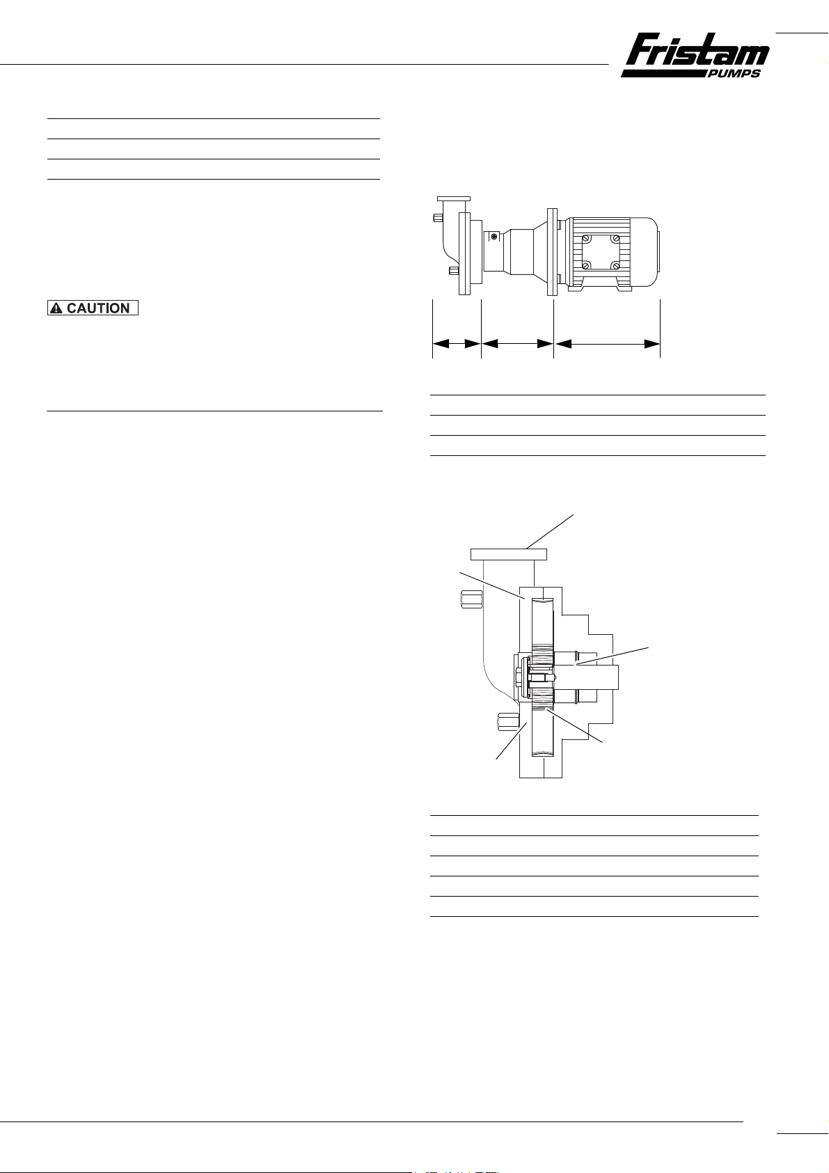
3 Design and Function
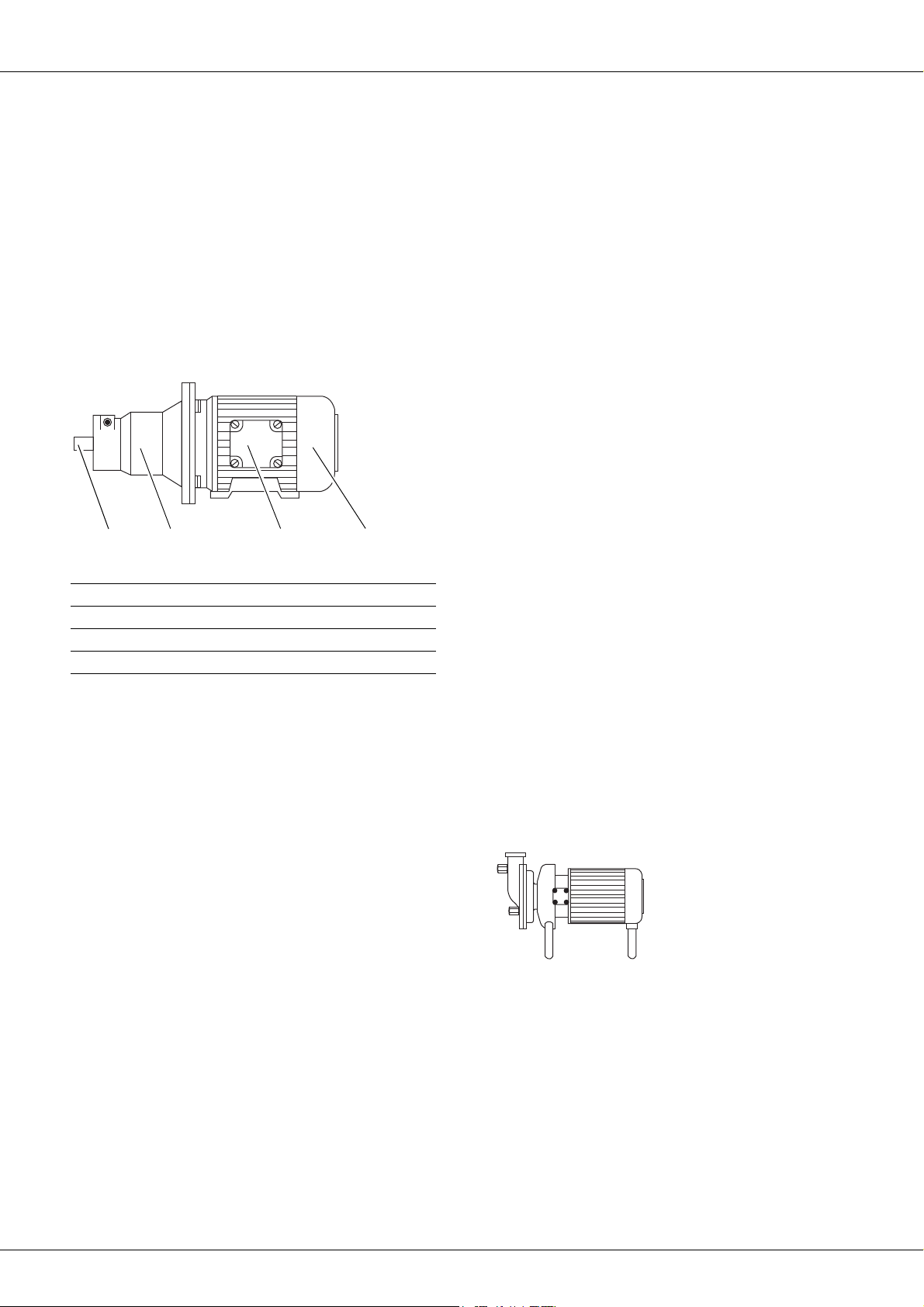
3.1 Principles of Design
Fig. 5 Principles of design of pumps illustrated using the K model
Pump head
A
Lantern
B
Electric motor
C
2.6.1 Disposal of Transportation Package
► Recycle the transportation package.
2.6.2 Models K, KF, and L 1: Disposal of Grease
► Dispose of grease and objects saturated with grease in an
environmentally friendly manner in accordance with applicable regulations.
2.6.3 Model L 2: Disposal of Lubricating Oil
► Dispose of oil and objects saturated with oil in an environ-
mentally friendly manner in accordance with applicable regulations.
2.6.4 Disposal of Pump
1. Carefully clean the pump. Dispose of residues in an environmentally friendly manner in accordance with applicable regulations.
2. Dismantle the pump into its constituent parts.
3. Dispose of the pump parts in an environmentally friendly
manner in accordance with applicable regulations.
2.6.5 Disposal of Electrical and Electronic Scrap
► Dispose of electrical and electronic scrap in accordance with
applicable directives.
3.1.1 Pump Head (A)
Fig. 6 Pump head
Suction/discharge line connection
11
Shaft seal
12
Impeller
13
Pump cover
14
Pump casing
15
Shaft Seal (12)
Two seal types are available for use:
– Single shaft seal
– Double shaft seal
With the double shaft seal, there are two additional connections
for the sealing liquid on the pump casing. These connections are
not shown in the figures in this operator's manual.
7
/ / FZ PUMP SERIES / / /
16 17 18 19
Impeller (13)
Open impellers with radial blades are standardly used in the
FZ pump series.
Pump Cover (14)
The connections for the suction and discharge lines are located
on the pump cover.
Pump Casing (15)
The impeller and the shaft seal are built into the pump casing.
3.1.2 Lantern (B) and Electric Motor (C)
Fig. 7 Lantern and electric motor
Pump shaft
16
Lantern
17
Electrical connection
18
Electric motor
19
Lantern (16)
The lantern is present in all models except the special motor.
The lantern connects the pump casing to the motor. Two different versions are possible, depending on pump size:
– The pump casing is screwed to the lantern via a flange con-
nection.
– The pump casing is inserted into the lantern and mounted
with a clamp.
Models with lanterns:
–FZP
–K
Compact bearing support. An additional bearing for the
pump shaft is located inside the lantern.
–KF
Compact bearing support with base. An additional bearing
for the pump shaft is located inside the lantern with base.
–L
Bearing block. An additional bearing for the pump shaft is
located inside the lantern with base. The pump shaft is connected to the motor via a coupling.
Electric Motor (19)
The following motor types can be mounted:
– IEC standard motor with drive side fixed bearing (A side),
feather key and shaft pin of the following types:
– IM B3: motor model with base
– IM B5: motor model with flange
– IM B3/B5: motor model with flange and base
Various mounting types are possible for the IEC standard
motor:
–A Fristam pump shaft is clamped to the motor shaft pin.
– The motor is fastened to the flange on the compact bear-
ing support (with base).
– The motor is connected to the bearing block via a cou-
pling.
–Special motor with Fristam pump shaft
With the special motor, the Fristam pump shaft is already integrated and connected permanently to the motor.
3.2 Models
The model is indicated on the rating plate. See Chapter 2.4,
"Warning and Instruction Labels," page 6.
The following are shown as examples:
– Lantern clamp-mounted
– Without enclosure
See Chapter 3.4, "Versions," page 9.
3.2.1 Model FZ or FZP
Fig. 8 Model FZ with special motor
Motor: Special motor
Design: Without lantern
8
3.2.2 Model K
20 22 2321
Fig. 9 Model KF
Motor: IEC standard motor, motor model B3/B5
Design: Compact bearing support
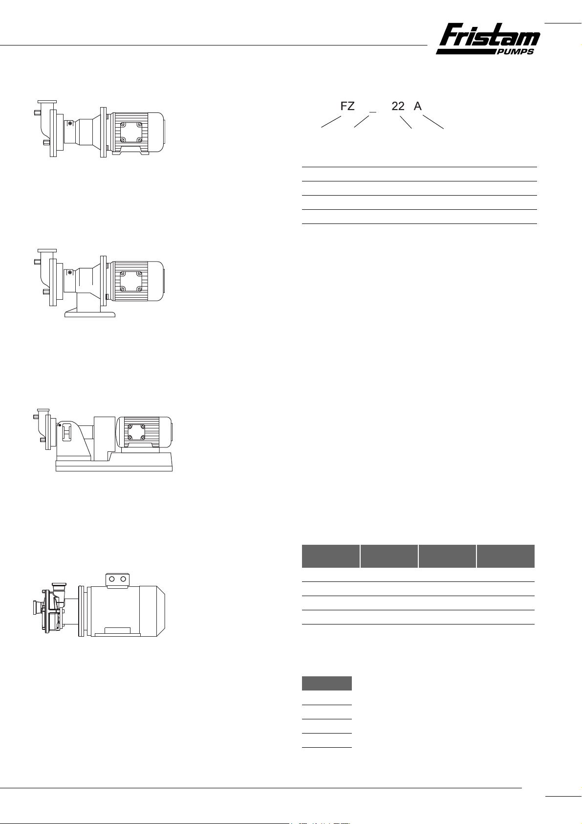
3.3 Pump Key
Fig. 13 Type designation example
Pump type
20
Supplementary character 1
21
Pump size
22
Supplementary character 2
23
3.2.3 Model KF
Fig. 10 Model KF
Motor: IEC standard motor, motor model B5
Design: Compact bearing support with base
3.2.4 Model L
Fig. 11 Model L
Motor: IEC standard motor, motor model B3
Design: Bearing block with coupling, coupling protec-
tion, base frame
(20) Pump Type
FZ Side channel pump
(21) Supplementary Character 1
P Sampling pump (FZ 10)
(22) Pump Size
__ Sizes: see Chapter 3.5, "Pump Sizes," page 9.
(23) Supplementary Character 2
PM Powder mixer
A, B, C, D Versions; see Chapter 3.4, "Versions," page 9:
K Compact bearing support
KF Compact bearing support with base
L1, L2
Bearing block with coupling
H Pump casing with heating jacket
h Pump cover with heating jacket
3.4 Versions
3.2.5 Design FZ 27
Fig. 12 Design FZ 27
Motor: IEC standard motor, model B3/B5
Design: With lantern
Version Enclosure Spherical Cap
Legs
A With With Without
B Without Without With
C Without With Without
D With Without With
Tab le 1 Versions
3.5 Pump Sizes
Pump Sizes
10
15
17
20
Tab le 2 P ump si ze s
Motor Foot
9
/ / FZ PUMP SERIES / / /
Pump Sizes
22
25
27
Tab le 2 P ump si ze s
Note: If the (optional) pump without motor is supplied, please
first read Chapter 11, "Appendix 2 – Assembly Instructions (Option-
al)," page 36.
4Transportation
Transportation may only be performed by trained personnel.
The pump can be moved using an industrial truck or a crane.
Always move the pump in the installation condition.
4.1 Safety Instructions
► Danger of injury from falling or unsecured parts.
– Only use suitable means of conveyance and hoists. Infor-
mation on pump weight can be found on the pump's rating plate as well as in the Order-Related Documents in Ap-
pendix 2.
– Before moving the pump secure it to prevent it from tip-
ping over. Secure the pump to the pallet with tie-down
straps, or screw the pump to the pallet.
– Do not leave the pump in a raised position for longer
than necessary.
► Damage to pump by contamination, impact, or moisture.
– Remove the pipe fitting covers just prior to connection to
the pipes.
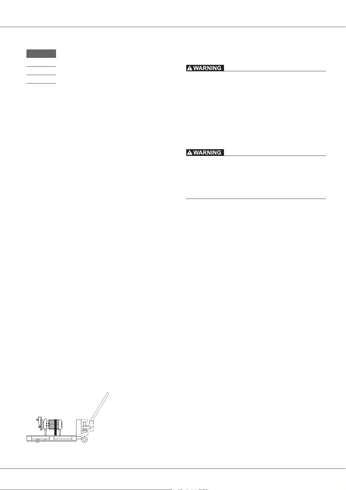
4.2 Moving With Industrial Trucks
Preparation
► Ensure that the pump is adequately secured to the pallet.
Procedure
1. Pick up the pallet with the forks on the industrial truck.
2. Carefully move the pallet to the designated location and set
down.
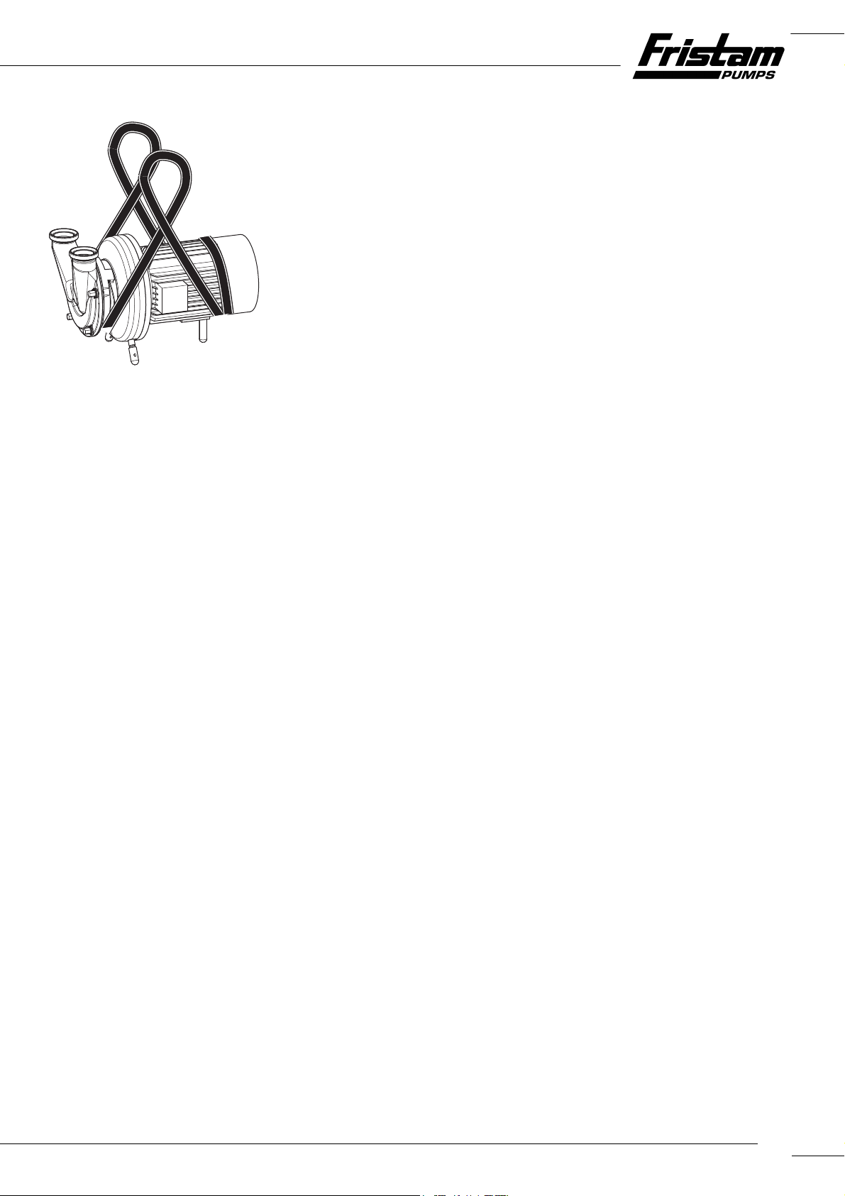
4.3 Moving With Crane
Falling Parts
Death from crushing, pinching of extremities, material damage.
► Do not lift the pump at the eyebolts on the motor and pump
casing to move because these eyebolts are not designed for
the total weight.
► Only use hoists that are designed for the total weight of the
pump.
► Ensure that the area below the pump is clear of people.
Swinging Parts
Crushing and serious injuries.
► Start and stop the crane with pump smoothly.
► Ensure that the danger zone of the pump is clear of people.
Auxiliary Equipment
Hoists: round slings tested in accordance with DIN EN 1492-1
and 1492-2
Preparation
► Remove load-securing devices.
Procedure
1. Wrap the round sling twice around the back end of the motor. Do not lay over the fan shroud (see Fig. 15, "Moving with
crane," page 11).
2. Lay the other end of the round sling between the lantern
and the pump casing. Do not lay the round sling over any
sharp edges or corners.
3. Guide both loops to the crane hook and rotate by 180° to ensure that the belt will not slip on the hook.
4. For double shaft seal:
Note: Round sling compresses sealing water tubes. Material
damage to double shaft seal.
► Do not lay the round sling on the sealing water tubes.
5. Position the center of gravity to ensure that the pump is lifted horizontally.
6. Lift the pump.
Fig. 14 Moving with industrial truck
10
.
Fig. 15 Moving with crane
5.3.1 Storage of Elastomers
Storage Conditions
– Storage temperature between +5°C and +20°C
– Relative air humidity below 70%
– No direct sunlight
– Deformation-free storage
5.4 Recommissioning
► After long-term storage and before commissioning, check
seals, bearings, and lubrication.
6Installation
5Storage
5.1 Safety Instructions
► Corrosion: Condensation can build up under a tarp and de-
stroy the pump. Ensure adequate ventilation.
5.2 Storage Conditions
► Store the pump as follows:
– Dry, in low humidity
– Protected against frost and heat, optimally at a tempera-
ture of +20°C to +25°C
– Ventilated
– Dust-free
5.3 Long-Term Storage
For a storage time of longer than six months, heed the following:
► The shaft seals must be specially treated before long-term
storage:
– For single shaft seal
The impeller nut must be loosened so that the seal can
relax and the sliding surfaces do not stick together.
– For double shaft seal
Remove the complete shaft seal and store separately to
prevent the sliding surfaces from sticking together.
Information on the shaft seal can be found in the Order-Re-
lated Documents in Appendix 2.
► All movable pump parts must be rotated every three
months.
6.1 Safety Instructions
► Danger of injury from falling parts.
– Wear safety shoes.
– Check load capacity and attachment of hoists.
► Danger of injury from unstable assembly.
– Tighten screws to the specified tightening torque (see
Chapter 10.1.1, "Tightening Torques for Screws and Nuts,"
page 31).
– Use a torque wrench or an impact driver with adjustable
torque.
► Material damage from swinging during adjustment of spher-
ical cap feet.
– Use spherical cap base plates.
6.2 Installation Location
For standard pumps, the installation location must meet the following requirements:
– Nonexplosive atmosphere
– Dust-free environment
– Ambient temperature: –20°C to +40°C
– Moisture and salt contents in ambient air:
The values are given in the motor supplier documentation. It
can be found in the attached documents (Appendix 2).
– Foundation sized adequately for the pump weight
– Horizontal and level installation surface, adequate installa-
tion surface strength for pump mass
– Adequate clearance for maintenance work
– Adequate air supply for motor cooling
11
/ / FZ PUMP SERIES / / /
6.3 Reduction of Noise and Vibration
6.3.1 Primary Measures
► Operate the pump in the optimum working range.
Note: Pump must not be blocked during operation. Pump
may only be throttled to the minimum allowable flow rate;
see "Performance Chart."
► Decouple the suction and discharge lines from vibrations.
– Support lines.
– Align lines.
– Install vibration isolators.
6.3.2 Secondary Measures
► Take structural measures such as the following:
– Acoustic paneling
– Enclosure in housing
6.4 Pump Fixation
Models FZ/K/FZP
► Versions A and C:
Set up the pump on the spherical cap bearings and align.
► Versions B and D:
Screw the pump on the motor foot to the foundation.
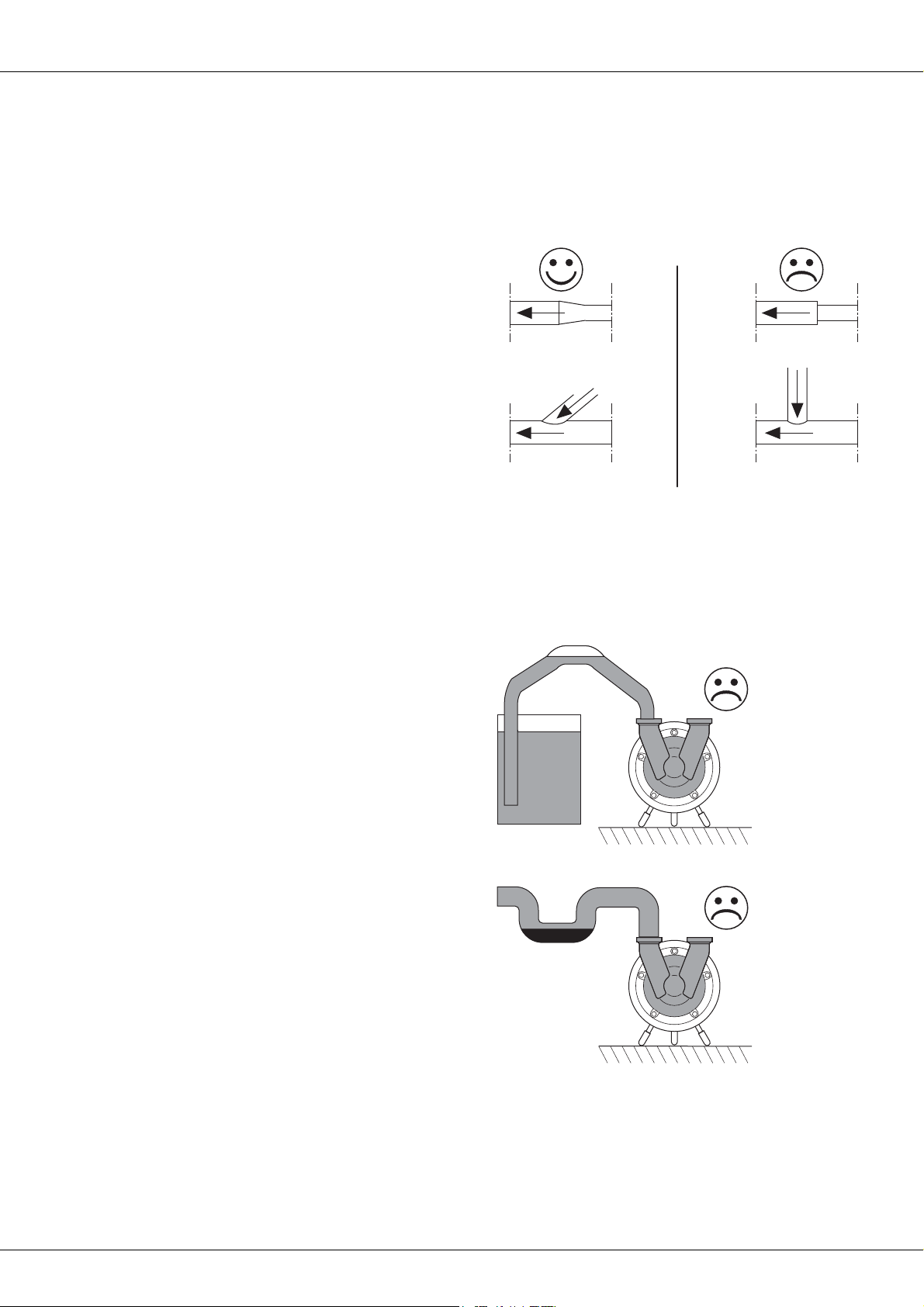
6.4.1 Installation of Pipes
► Lay and connect pipes as follows:
– Keep the pipe resistance as low as possible: Avoid unnec-
essary installation of valves, elbows, and abrupt pipe
transitions.
Fig. 16 Pipe transitions
– Design pipe cross section so that no unnecessary pres-
sure losses or cavitation occurs in the suction area. Verify
this in the project planning stage.
– Install the suction lines in horizontal position or at a con-
stant dropping angle towards the pump unit. Rule out
the possibility of air pockets and dips in the pipes.
Model KF
► Versions A and C:
Set up the pump on the spherical cap bearings and align.
► Versions B and D:
Screw the pump on the compact bearing support with base
to the foundation.
Model L
► Versions A and C:
Set up the pump on base frame on the spherical cap bearings and align.
► Versions B and D:
Screw the pump on the base frame to the foundation.
Design FZ 27
► Versions A and C:
Install and align the pump on the spherical cap bearings.
► Versions B and D:
Screw the pump on the pump base to the foundation.
Carriage (Optional)
1. Set up the pump at the installation location. Lock the locks
on the rollers (if present) or secure the carriage with chocks.
2. Ground the carriage to dissipate electrostatic charge.
3. Position hose line to ensure that it cannot be damaged.
Fig. 17 Air pocket in pipe
Fig. 18 Dip in pipe
– Pipe bends upstream of suction connection: Heed mini-
mum clearance and minimum bend radius:
12
 Loading...