

Fristam Pump FM Series, FM5, FM3 Instruction And Maintenance Manual

INSTRUCTION AND MAINTENANCE MANUAL:
FM SE R I E S PU M P
FM Series Pump
1
SANITARY CENTRIFUGAL PUMPS

Fristam Pumps
DE S C R I P T I O N
This manual contains installation, operation, assembly, disassembly and repair instructions for the Fristam
FM multi-stage pump.
The motors are standard NEMA totally enclosed fan cooled (TEFC) motors. These motors do require feet.
Replacement motors are readily available from local motor distributors.
2
CAUTION: BEGIN ALL PUMP MAINTENANCE OPERATIONS BY DISCONNECTING THE ENERGY SOURCE
TO THE PUMP. OBSERVE ALL LOCK OUT/TAG OUT PROCEDURES AS OUTLINED BY ANSI Z244.1-1982
AND OSHA 1910.147 TO PREVENT ACCIDENTAL START-UP AND INJURY.

TA b L E O F CO N T E N T S
Te c h n i c a l in f o r m a T i o n ........................................................................................................................... 4-5
P
r e v e n T i v e ma i n T e n a n c e ............................................................................................................................ 5
i
n s T a l l a T i o n ...........................................................................................................................................6-9
s
e
W
s
P
a r T s li s T .......................................................................................................................................... 10-12
a
s s e m b l y Dr a W i n g s ............................................................................................................................10-14
fm3 (hP3) s
fm5 (hP4) s
fm3 e
fm5 e
e
s
e a l re P l a c e m e n T ..............................................................................................................................16-19
P
P
s
h a f T a n D /o r be a r i n g re P l a c e m e n T .................................................................................................... 20-22
b
b
c
h e c k i n g T h e im P e l l e r ga P ..................................................................................................................... 23
W
a r r a n T y ................................................................................................................................................ 24
h a f T al i g n m e n T .......................................................................................................................... 8
l e c T r i c a l in s T a l l a T i o n ............................................................................................................... 9
a T e r fl u s h in s T a l l a T i o n ............................................................................................................ 9
T a r T -u P in s T r u c T i o n s .................................................................................................................. 9
e a l as s e m b l y ........................................................................................................ 10
e a l as s e m b l y ........................................................................................................ 11
x P l o D e D Pu m P he a D as s e m b l y .......................................................................................... 12
x P l o D e D Pu m P he a D as s e m b l y .......................................................................................... 13
x P l o D e D be a r i n g bl o c k as s e m b l y ............................................................................................. 14
u m P he a D Di s a s s e m b l y ............................................................................................................. 16
u m P he a D as s e m b l y ............................................................................................................. 17-19
e a r i n g bl o c k Di s a s s e m b l y ........................................................................................................ 20
e a r i n g bl o c k as s e m b l y .......................................................................................................21-22
FM Series Pump
3

Fristam Pumps
Te c h n i c a l in f o r m a T i o n
Sp e c i f i c a T i o n S
Maximum Inlet Pressure ........................................................................................................... 1000 PSI
Temperature Range ............................................................................................................-40°F - 400°F
Noise Level ...........................................................................................................................60 - 85 dB(A)
ST a n d a r d ma T e r i a l S o f co n S T r u c T i o n (no T e : oT h e r o p T i o n S a v a i l a b l e )
Product Contact Components ......................................................................... AISI 316L Stainless Steel
Pump Seal Components
Single Rotating Seal .................316L Stainless Steel with Silicon Carbide Insert (silver/gray)
Stationary Seals ......................................................................................Silicon Carbide (black)
Double Rotating Seal .......................................................................................... Carbon (white)
Product Contact Surface Finish ..................................................................................................32 in Ra
Gaskets / O-rings ............................................................................................................................. Viton
Bearing Block ............................................................................................................................Cast Iron
Se a l in f o r m a T i o n
Double Mechanical
Recommended Seal Flush Pressure ..................................................................5 PSI Maximum
Recommended Seal Flush Flow ............................................................... 1-2 Gallons per Hour
4
re c o m m e n d e d To r q u e va l u e S
Cover Nuts .................................................................................................................................105 ft-lbs
Impeller Nut
FM3 .................................................................................................................................40 ft-lbs
FM5 .................................................................................................................................90 ft-lbs
Seal Retaining Ring Bolts .............................................................................................................5 ft-lbs
Seal Driver Set Screw (FM3 only) .............................................................................................. 10 in-lbs
Housing Bolts ..............................................................................................................................50 ft-lbs
Bearing Cap Bolts ........................................................................................................................10 ft-lbs
Bearing Locknut ..........................................................................................................................50 ft-lbs
im p e l l e r Ga p S (im p e l l e r T o ho u S i n G )
All FM Pumps ...............................................................................................0.8-1.0 mm ( 0.030-0.040”)
lu b r i c a T i o n
Bearing Block Oil ....................................................................................................................ISO VG 68

FM Series Pump
To o l s f o r As s e m b l y & Di s A s s e m b l y
7/16” socket ....................................................................................................Seal Retaining Ring Bolts
Ratchet ..................................................................................................................... For loosening bolts
Torque wrench ...................................................................................................... For proper tightening
Adjustable pliers ............................................................................................ For removing Water Pipes
Chain wrench........................... For holding the Shaft when tightening & loosening the Impeller Nut
Food grade lubricant ..........................................................................For lubricating o-rings & gaskets
Standard screwdriver ............................................ For installing & removing the Bearing Lockwasher
Soft-face hammer .......................................................................... For installing & removing the Shaft
Feeler gages .....................................................................................................For gapping the Impeller
FM3 Tools
15/16” socket .............................................................................................................Cover Nuts
1” socket .................................................................................................................Impeller Nut
3/32” Allen wrench socket ...........................................................Double Seal Driver Set Screw
3/4” socket ............................................................................................................Housing Bolts
1/2” socket ......................................................................................................Bearing Cap Bolts
M50 Spanner wrench .......................................................................................Bearing Locknut
FM5 Tools
24mm socket .............................................................................................................Cover Nuts
32mm socket ..........................................................................................................Impeller Nut
18mm socket ........................................................................................................Housing Bolts
13mm socket ..................................................................................................Bearing Cap Bolts
M65 Spanner wrench .......................................................................................Bearing Locknut
5
re c o m m e n D e D Pr e v e n T i v e mA i n T e n A n c e
re c o m m e n D e D se A l mA i n T e n A n c e
Visually inspect mechanical seal daily for leakage.
Replace mechanical seal annually under normal duty.
Replace mechanical seal as often as required under heavy duty.
el A s T o m e r in s P e c T i o n
Inspect all elastomers when performing pump maintenance. We recommend replacing elastomers (orings and gaskets) during seal, pump shaft and/or motor replacement.
lu b r i c A T i o n
The oil level should be maintained to the center of the sight glass on the side of the bearing block. The
oil should be changed every 2,000 hours or 3 months under normal operating conditions. Make sure
the oil drain pipe and cap are properly tightened to prevent any oil leakage from the bearing block.
mo T o r mA i n T e n A n c e
Consult motor manufacturer for recommended maintenance.
Fristam Pumps
1265000340 Rev-
IN S T A L L A T I O N
UN P A C k I N G
Check the contents and all wrapping when unpacking the pump. Inspect the pump carefully for any
damage that may have occurred during shipping. Immediately report any damage to the carrier.
Remove the shaft guard and rotate the pump shaft by hand to make sure the impeller rotates freely.
Keep the protective caps over the pump inlet and outlet in place until you are ready to install the
pump.
IN S T A L L I N G
Prior to actually installing the pump, ensure that:
• The pump will be readily accessible for maintenance, inspection and cleaning.
• Adequate ventilation is provided for motor cooling.
• The drive and motor type is suitable for the environment where it is to be operated. Pumps
intended for use in hazardous environments (i.e. explosive, corrosive, etc.) must use a motor and
drive with the appropriate enclosure characteristics. Failure to use an appropriate motor type
may result in serious damage and/or injury.
PI P I N G GU I D E L I N E S
This section describes good piping practices to obtain maximum efficiency and service life from your
pump.
Maximum performance and trouble-free operation require adherence to good piping practices.
6
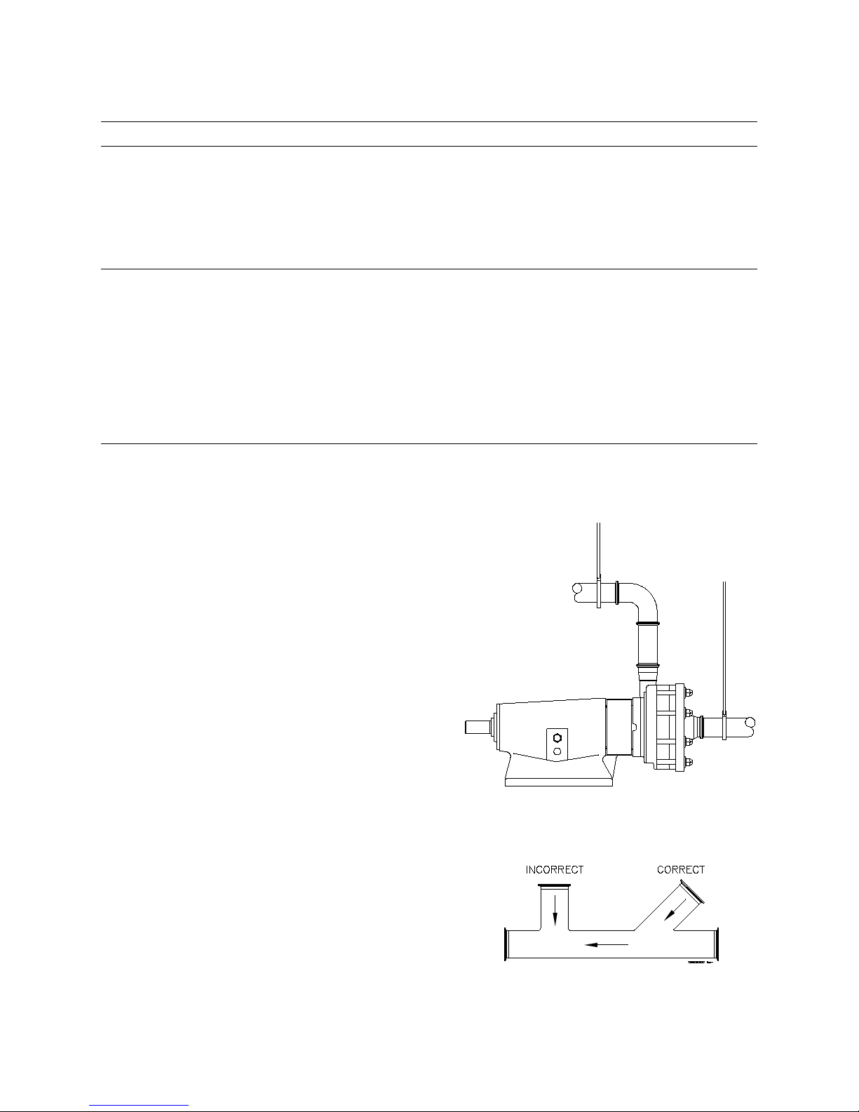
FI G U R E 1
Ensuring proper piping support and alignment at both
the suction inlet and discharge outlet can help prevent
serious damage to the pump housing.
FI G U R E 2
Avoid abrupt transitions in the piping system.
Avoid throttling valves in the suction piping.
Keep suction lines as short and direct as possible.
Ensure that the NPSH available in the system is greater
than NPSH required by the pump.
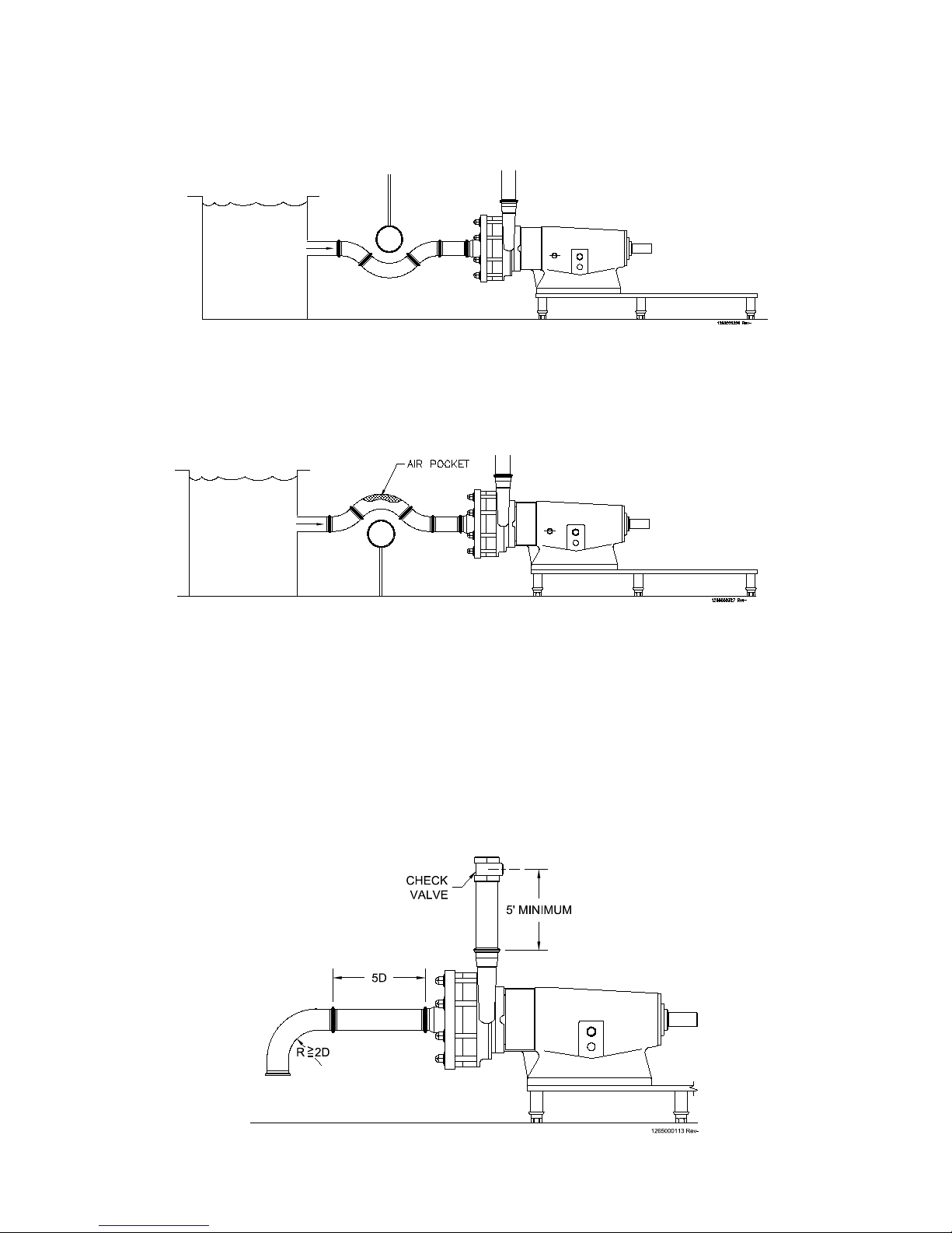
FI G U R E 3
Avoid sump areas where sediments may collect.
FI G U R E 4
Avoid the formation of air pockets in the piping.
FM Series Pump
7
FI G U R E 5
Avoid abrupt closure of shut-off valves, this may cause hydraulic shock which can cause severe damage
to the pump and system.
Avoid elbows in the suction line if possible. When necessary they should be located 5 pipe diameters
away from the pump inlet, and have a bend radius greater than 2 pipe diameters.
Check valves in discharge line should be a minimum of 5 ft. away from the pump outlet.
Fristam Pumps
A
Y
MAX.
Y
MIN.
PARALLEL
ANGULAR
1265000238 REV. -
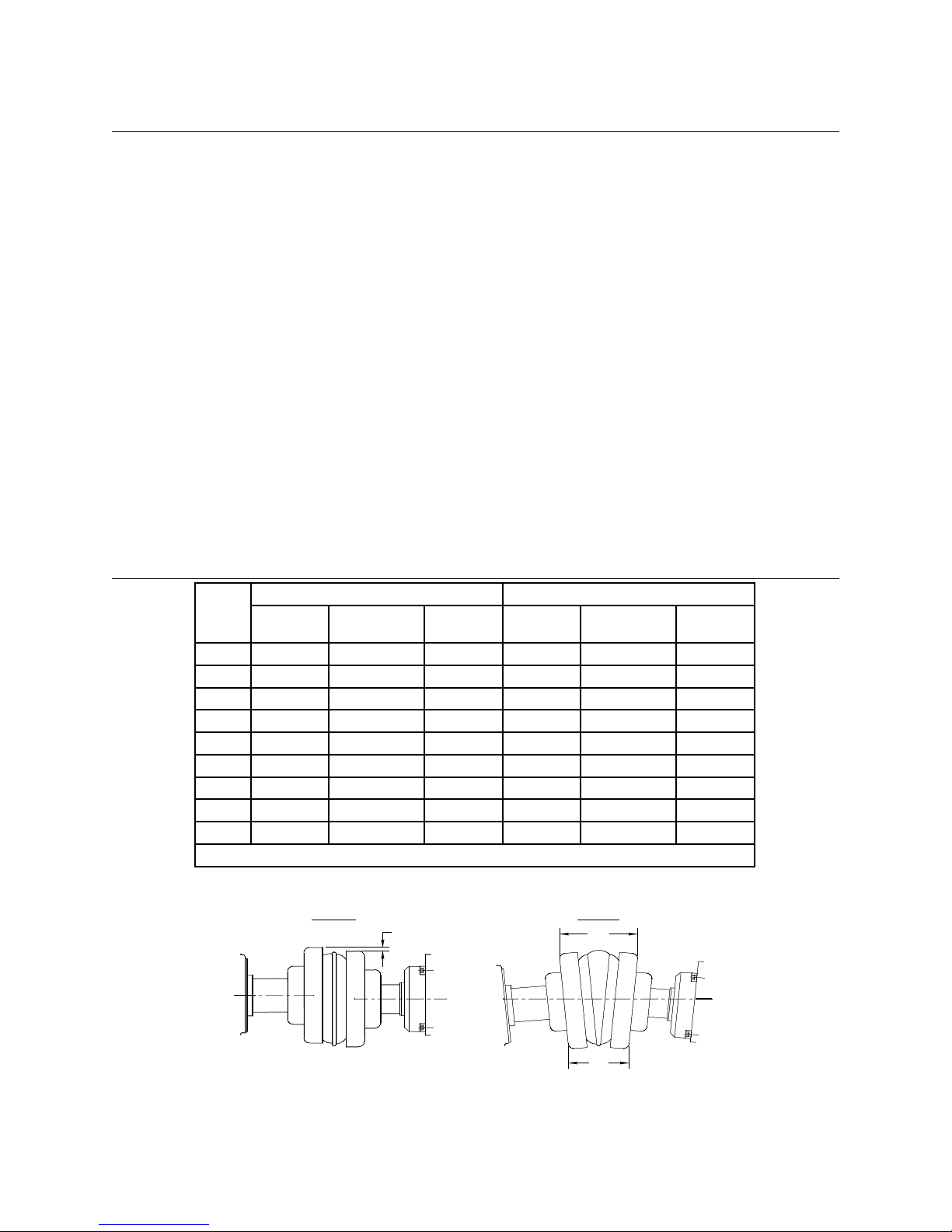
AL I G N M E N T
In most cases, the pump will be shipped with a drive unit mounted on a baseplate. The drive and pump
are aligned at the factory; however, this alignment should be checked after installation (Figure 6). Misalignment between the pump and drive can result in premature bearing failure or other damage. If the
pump is not shipped with a drive unit, use a flexible coupling between the pump and drive unit. Align
the pump and drive unit according to the coupling requirements.
To check the alignment:
• Remove the wire ring from the coupling sleeve and let it hang between the sleeve and one of the
flanges.
• To check the parallel alignment place a straight edge across the two coupling anges and measure the maximum offset at various points around the periphery of the coupling without rotating the coupling. If the maximum offset exceeds the figure shown under “Parallel” in the table,
realign the shafts.
• Check the angular alignment with a micrometer or caliper. Measure from the outside of one
flange to the outside of the other (“Y”) at intervals around the periphery of the coupling. Determine the maximum and minimum dimensions without rotating the coupling. The difference
between the maximum and minimum must not exceed the figure given under “Angular” in the
table. If a correction is necessary be sure to recheck the parallel alignment.
• Reinstall the wire ring on the O.D. of the coupling sleeve.
WO O D S SU R E -FL E x CO U P L I N G AL I G N M E N T
Sleeve
Size
6 0.015” 0.070” 2.375” 0.015” 0.070” 2.375”
7 0.020” 0.081” 2.563” 0.020” 0.081” 2.563”
8 0.020” 0.094” 2.938” 0.020” 0.094” 2.938”
9 0.025” 0.109” 3.500” 0.025” 0.109” 3.500”
10 0.025” 0.128” 4.063” 0.025” 0.128” 4.063”
11 0.032” 0.151” 4.875” 0.032” 0.151” 4.875”
12 0.032” 0.175” 5.688” 0.032” 0.175” 5.688”
13 0.040” 0.195” 6.688” 0.040” 0.195” 6.688”
14 0.045” 0.242” 7.750” 0.045” 0.242” 7.750”
* The “Y” dimension is shown for reference.
Parallel
A
Type E Type E
Angular
Y max. - Y min.
Y*
Parallel
A
Angular
Y max. - Y min.
Y*
8
FI G U R E 6
 Loading...