

Frisco Eclipse 73 Series Installation Manual
73 Series Door Closer Installation
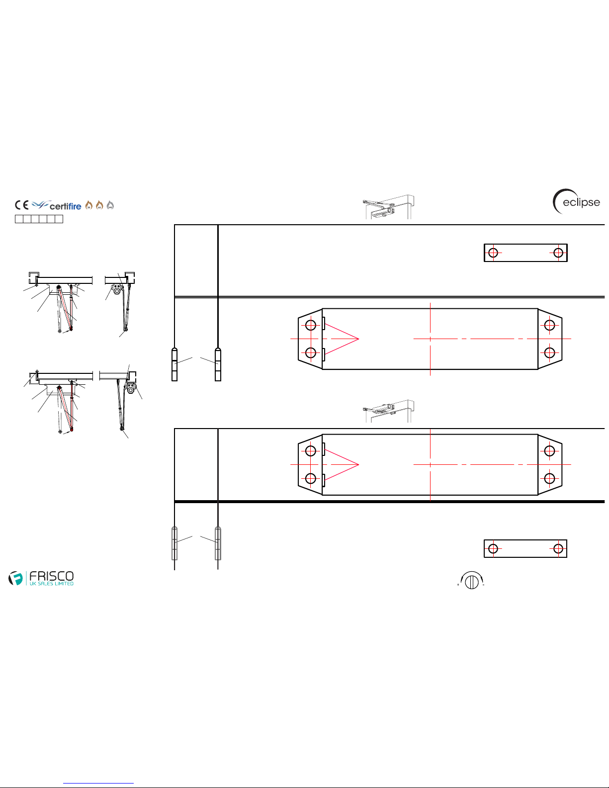
Standard Door Installation (Pull Side) - Fig 1
Frame Fix Installation (Push Side) - Fig 61
To Increase Closing Speed:
Adjust screw valve (1) anti-clockwise by quarter turns until desired speed has been achieved
To Reduce Closing Speed:
Adjust screw valve (1) clockwise by quarter turns until desired speed has been achieved
To Increase Latching Speed:
Adjust screw valve (2) anti-clockwise by quarter turns until desired speed has been achieved
To Reduce Latching Speed:
Adjust screw valve (2) clockwise by quarter turns until desired speed has been achieved
CAUTION
Adjusting valves more than 2 full turns anti-clockwise from factory settings will result in oil leakage damaging the door closer.
Hinge knuckle
is visable
Hinge knuckle
is not visable
Door Frame
Door
Door Frame
Door
Step by Step Installation Guide
Use the appropriate template for your installation and place
the template on the door and frame. Pilot drill all fixing holes
as per the template.
1. Position the door closer with the adjustment valves facing
the hinge side of the door. Secure the door closer using
the screws provided into the pre-drilled pilot positioning
holes.
2. Attach the armset to the pivot on the door closer body and
secure using the washer screw.
3. Tension the door closer arm and adjust the arm length
accordingly. Secure the arm set shoe to the door or frame
depending on installation, then tighten the arm set nut.
4. Apply the dust cap to the unused pivot.
5. Adjust the closing and latching speeds as required refer to adjustment instructions.
NB after the first month of operation the closing and latching
speed valves may require minor adjustment.
2 - Latching Speed
Adjustment Valves
Adjustment Valves
1 - Closing Speed
2 - Latching Speed
1 - Closing Speed
2 - Latching Speed
1 - Closing Speed
Door Closer Body
Door Closer Body
Armset Shoe
Armset Shoe
120 degree
door installation
180 degree
door installation
120˚ door
installation
180˚ door
installation
Standard Door Installation
Pull Side - Fig 1
Frame Fix Installation
Push Side - Fig 61
Washer Screw
Dust Cap
Armset Pivot Screw
Hinge Knuckle
Adjustment Valves
Door Closer Body
Preload
Armset
Nut
Threaded
Arm (bolt)
Armset Shoe
Hinge Knuckle
Adjustment Valves
Door Closer Body
Preload
Armset
Nut
Threaded
Arm (bolt)
Armset Shoe
Washer Screw
Armset Pivot Screw
Dust Cap
acceleration deceleration
Unit 14 Pindar Road, Hoddesdon, Hertfordshire, EN11 0DE
Tel: +44 (0)1992 443 010 | Fax: +44 (0)1992 443 020
EN1154:1997 + A1:2002 *Fig 1 application only
EN1634-1:2000 FD60 timber FD240 steel
CE 1121-CPD-AD1069 (2007)
Certifire CF600
3 8 3 1 1 3
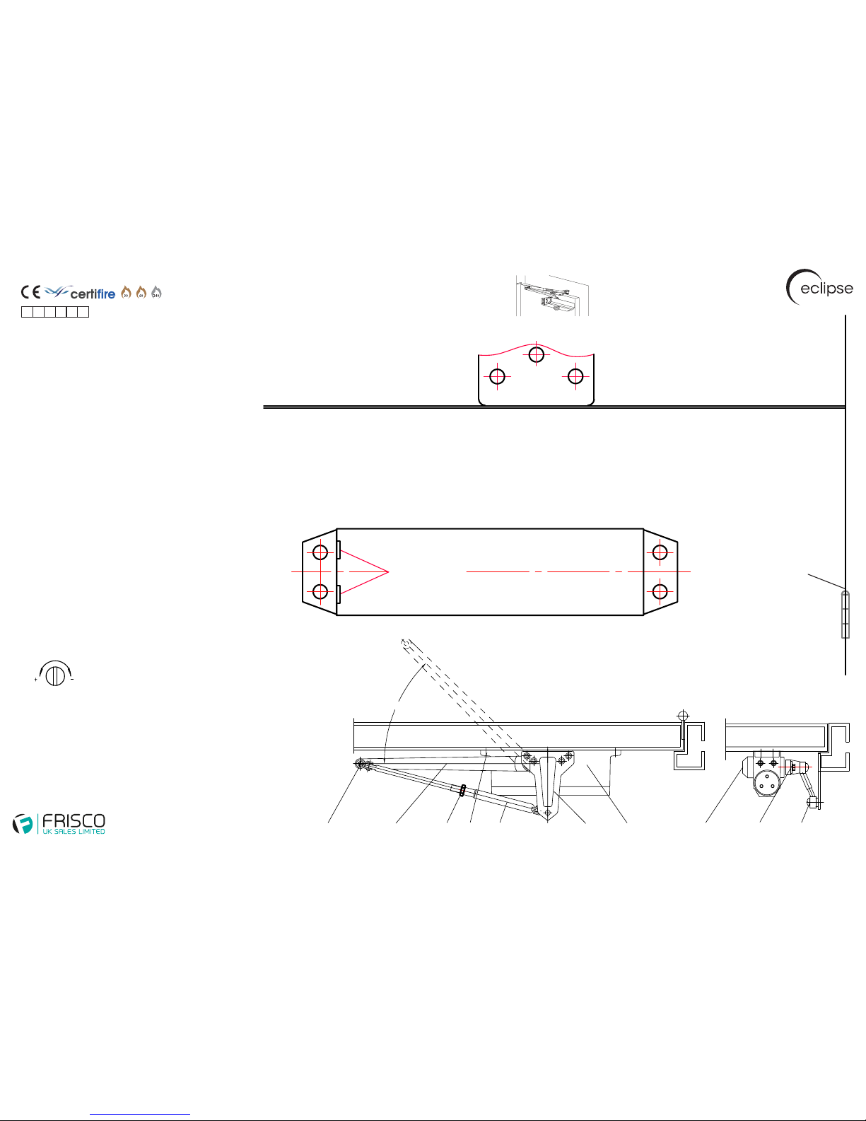
Key
1. Armset Pivot Screw
2. Armset
3. Nut
4. Adjustment Valves
5. Threaded Arm (Bolt)
6. Parallel Bracket
7. Door Closer Body
8. Dust Cap
9. Washer Screw
10. Assembling Screw
1 2 3 4 5 6 7 8 9 10
45˚ Preload
73 Series Door Closer Installation
Parallel Arm Installation (Push Side) - Fig 66
Door Closer Body
Adjustment Valves
2 - Latching Speed
1 - Closing Speed
Parallel
Arm Bracket
To Increase Closing Speed:
Adjust screw valve (1) anti-clockwise by quarter turns until desired speed has been achieved
To Reduce Closing Speed:
Adjust screw valve (1) clockwise by quarter turns until desired speed has been achieved
To Increase Latching Speed:
Adjust screw valve (2) anti-clockwise by quarter turns until desired speed has been achieved
To Reduce Latching Speed:
Adjust screw valve (2) clockwise by quarter turns until desired speed has been achieved
CAUTION
Adjusting valves more than 2 full turns anti-clockwise from
factory settings will result in oil leakage damaging the door closer.
acceleration deceleration
Hinge knuckle
is not visable
Door Frame
Door
Unit 14 Pindar Road, Hoddesdon, Hertfordshire, EN11 0DE
Tel: +44 (0)1992 443 010 | Fax: +44 (0)1992 443 020
EN1154:1997 + A1:2002 *Fig 1 application only
EN1634-1:2000 FD60 timber FD240 steel
CE 1121-CPD-AD1069 (2007)
Certifire CF600
3 8 3 1 1 3
Step by Step Installation Guide
Use the appropriate template for your installation and place
the template on the door and frame. Pilot drill all fixing holes
as per the template.
1. Position the door closer with the adjustment valves facing
away from the hinge side of the door. Secure the door closer
and bracket using the screws provided into the pre-drilled
pilot positioning holes.
2. Remove the shoe from the door closer arm.
3. Attach the armset to the pivot on the door closer body parallel
to the door/frame and secure using the washer screw.
4. Tension the door closer arm and adjust the arm length
accordingly. Secure the arm to the figure 66 bracket and tighten
the arm set nut.
5. Add the dust cap to the unused pivot.
6. Adjust the closing and latching speeds as required refer to adjustment instructions.
NB after the first month of operation the closing and latching
speed valves may require minor adjustment.
 Loading...